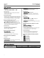
1
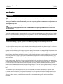
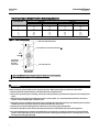
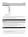
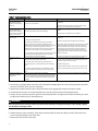
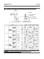
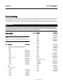
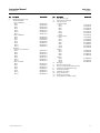
Instruction Manual
9500 Valve
D100380X012
July 2012
Fisherr 9500 Butterfly Control Valve
Contents
Introduction . . . . . . . . . . . . . . . . . . . . . . . . . . . . . . . . . 1
Scope of Manual . . . . . . . . . . . . . . . . . . . . . . . . . . . . . 1
Description . . . . . . . . . . . . . . . . . . . . . . . . . . . . . . . . . 1
Installation . . . . . . . . . . . . . . . . . . . . . . . . . . . . . . . . . . 3
Adjustments . . . . . . . . . . . . . . . . . . . . . . . . . . . . . . . . . 6
Hub Seals . . . . . . . . . . . . . . . . . . . . . . . . . . . . . . . . . . 6
Linkage . . . . . . . . . . . . . . . . . . . . . . . . . . . . . . . . . . . . 8
Three-Way Valve Tandem Linkage . . . . . . . . . . . . . . 8
Maintenance . . . . . . . . . . . . . . . . . . . . . . . . . . . . . . . . . 9
Disassembly . . . . . . . . . . . . . . . . . . . . . . . . . . . . . . . . 9
Reassembly . . . . . . . . . . . . . . . . . . . . . . . . . . . . . . . . 11
Actuator Mounting . . . . . . . . . . . . . . . . . . . . . . . . . . . 13
Changing Disc Rotation and Action . . . . . . . . . . . . . 14
Parts Ordering . . . . . . . . . . . . . . . . . . . . . . . . . . . . . . . 16
Parts List . . . . . . . . . . . . . . . . . . . . . . . . . . . . . . . . . . . 16
Figure 1. Fisher 9500 Valve with 1052 Actuator and
DVC6200 Digital Valve Controller
W9224-2
Introduction
Scope of Manual
This manual provides installation, adjustment, and maintenance information for Fisher 9500 butterfly valves. These
valves use splined shafts with actuator-mounted brackets and linear-motion actuators (see figure 1). Refer to separate
manuals for instructions covering the power actuator or the manual handwheel actuator, positioner, and other
accessories.
Do not install, operate, or maintain 9500 valves without being fully trained and qualified in valve, actuator, and
accessory installation, operation, and maintenance. To avoid personal injury or property damage, it is important to
carefully read, understand, and follow all the contents of this manual, including all safety cautions and warnings. If you
have any questions about these instructions, contact your Emerson Process Management sales office before
proceeding.
Description
The 9500 valve is a fully lined butterfly valve for use with corrosive process fluids or wherever stringent shutoff is
required. The nitrile or PTFE liner completely isolates the valve body and shaft from the process fluid. The valve is
available with conventional or FISHTAIL™ disc designs.
www.Fisher.com
Instruction Manual
9500 Valve
July 2012
D100380X012
Table 1. Specifications
FISHTAIL Disc: Approximately equal percentage
through 90 degrees of disc rotation
Valve Sizes
NPS J 2, J 3, J 4, J 6, J 8, J 10, or J 12
Flow Direction
Valve Body Style
Conventional Disc: Bidirectional
FISHTAIL Disc: Forward flow - The tail of the disc
opens into the downstream end of the valve (see
figure 2).
Flangeless (wafer-type) valve body to be installed
between pipeline flanges
End Connection Styles
Flangeless (wafer-style) valve body mates with CL125
flat-face flanges per ASME B16.1, with CL150 and 300
raised-face flanges per ASME B16.34, or EN flanges
Disc Rotation
Conventional Disc
On/Off Service: J 0 to 60 or J 0 to 90 degrees
Maximum Allowable Inlet Pressure(1)
Throttling Service: 0 to 60 degrees
FISHTAIL Disc: 0 to 60 or 0 to 90 degrees for on/off or
throttling
Consistent with applicable pressure/temperature
ratings for JCL125B per ASME B16.1, or
JCL150 and 300 per ASME B16.34 unless limited by
maximum allowable pressure drop specification or by
material temperature capabilities in table 2
Shutoff Classification per ANSI/FCI 70-2 and IEC
60534-4
Nitrile Liner or PTFE Liner: Class VI
Vacuum Service
Mating Flange Capabilities
All sizes compatible with welding-neck flanges; also
see Installation section for slip-on flanges
The valve is suitable for vacuum service to
approximately 10-7 mm Hg absolute
(3.4 x 10⁻¹² mbar, absolute)
Code Classifications
Maximum Shutoff Pressure Drop(1)
Dimensions meet MSS SP-67 specifications for
face-to-face dimensions for flangeless valves
Standard Operation
Cast Iron Valve: 12.1 bar (175 psi)
Approximate Weights (Valve Body Assemblies
Only)
Steel or Stainless Steel Valve: 15.2 bar (220 psi)
Material Temperature Capabilities(1)
NPS 2: 9 kg (20 lb)
NPS 3: 11 kg (25 lb)
NPS 4: 14 kg (30 lb)
NPS 6: 20 kg (45 lb)
NPS 8: 27 kg (60 lb)
NPS 10: 32 kg (70 lb)
NPS 12: 54 kg (120 lb)
See table 2
Flow Characteristic
Conventional Disc: Approximately equal percentage
through 60 degrees of disc rotation
1. The pressure/temperature limits in this manual and any applicable standard or code limitation should not be exceeded.
Table 2. Operative Temperature
Disc Type
Conventional or FISHTAIL
2
Liner Material
Operative Temperature
Nitrile
-7 to 93_C (20 to 200_F)
PTFE
-18 to 121_C (0 to 250_F)
Instruction Manual
9500 Valve
D100380X012
July 2012
Installation
WARNING
Always wear protective gloves, clothing, and eyewear when performing any installation operations to avoid personal
injury.
Personal injury or equipment damage caused by sudden release of pressure may result if the valve assembly is installed
where service conditions could exceed the limits given in table 1 or on the appropriate nameplates. To avoid such injury or
damage, provide a relief valve for over-pressure protection as required by government or accepted industry codes and
good engineering practices.
Check with your process or safety engineer for any additional measures that must be taken to protect against process
media.
If installing into an existing application, also refer to the WARNING at the beginning of the Maintenance section in this
instruction manual.
These valves may be installed in many positions by referring to the Actuator Mounting procedures and figure 6 in this
manual. For conventional discs, flow may be in either direction. For FISHTAIL discs, the leading edge of the disc must
be located in the upstream end of the valve (see figure 2).
CAUTION
As noted in the following paragraphs, improper use of additional gasketing materials will damage the valve liner.
The valve body liner extends past or overlaps the valve face producing the partial O-ring shown in figure 3. It also acts
as the flange gasket. Improper use of additional gasketing materials will damage the valve liner.
Care must be taken during installation to ensure that the pipe flanges are properly supported. Pipe flange support is
required to avoid liner flange joint leakage or problems during valve operation. Slip-on pipe flanges may be used with
NPS 2, 3, or 4 valves. An NPS 6 valve or larger will require flange adapters for complete liner support.
Mating flanges or pipe flanges with inside diameters smaller than the minimum shown (see table 3) may interfere with
the opening of the disc. Flanges or pipes with an inside diameter larger than the maximum shown (see table 3) may
not be in full contact with the liner. Install flange adapters in each case, either to provide disc clearance or to fully
contact the liner.
Flexible, plastic flanges, fiberglass, slip-on, or weld-neck with other than standard inside diameters may not provide
adequate support for the liner. Also, flexible mating flanges can be warped with excessive line bolt load. They may fail
to support the liner at the inside diameter of the valve body. Use flange adapters, available from Emerson Process
Management, during installation to avoid these problems. Whenever a flange adapter is used, a standard flange
gasket must be installed between the line flange and flange adapter. Do not use a flange gasket between the valve and
flange adapter. The partial O-ring on the liner acts as the flange gasket and any additional gasket here will damage the
liner.
The 9500 valve may be used as part of a three-way valve assembly. The actuator-valve linkage is adjusted at the
factory; you won't need to adjust the linkage before placing the valve in service. If the valve and actuator are being
re-installed, after removal, or if you suspect that the linkage is out of adjustment, refer to the Linkage portion of the
Adjustments section before installing the valve in the pipeline. If the valve has been purchased separately, or if the
actuator has been removed, complete the procedures in the Actuator Mounting section of this manual before
proceeding.
3
Instruction Manual
9500 Valve
July 2012
D100380X012
Table 3. Maximum and Minimum Allowable Mating Flange Diameters
MAXIMUM AND MINIMUM DIAMETER OF MATING PIPING OR FLANGES
Minimum
VALVE SIZE, NPS
2
3
4
6
8
10
12
Maximum
mm
Inches
mm
Inches
30
64
89
145
196
246
297
1.20
2.50
3.50
5.70
7.70
9.70
11.70
64
92
117
171
222
273
330
2.50
3.62
4.62
6.75
8.75
10.75
13.00
Figure 2. Valve Shaft Marking
NOSE OR LEADING EDGE OF DISC
1
LOCATION OF FLAT SPOT ON VALVE SHAFT 2
OPEN
FLOW
LOCATION OF
INDEX MARK
ON END OF
VALVE SHAFT
1
TAIL OF FISHTAIL DISC
WITH SPLINED
VALVE SHAFT
1
EQUAL MEASUREMENTS BETWEEN VALVE FACE AND DISC EDGE AT TOP AND BOTTOM ENSURE FULLY CLOSED DISC.
2
FOR FISHTAIL DISC, PARTIAL KEYWAY OR FLAT SPOT IS ON SAME SIDE AS NOSE OF DISC.
A2755-1
WARNING
Avoid personal injury from sudden release of process pressure. Before performing any maintenance operations:
D Do not remove the actuator from the valve while the valve is still pressurized.
D Always wear protective gloves, clothing, and eyewear when performing any maintenance operations to avoid personal
injury.
D Disconnect any operating lines providing air pressure, electric power, or a control signal to the actuator. Be sure the
actuator cannot suddenly open or close the valve.
D Use bypass valves or completely shut off the process to isolate the valve from process pressure. Relieve process pressure
on both sides of the valve. Drain the process media from both sides of the valve.
D Vent the power actuator loading pressure and relieve any actuator spring precompression.
D Use lock-out procedures to be sure that the above measures stay in effect while you work on the equipment.
D The valve packing box may contain process fluids that are pressurized, even when the valve has been removed from the
pipeline. Process fluids may spray out under pressure when removing the packing hardware or packing rings, or when
loosening the packing box pipe plug.
4
Instruction Manual
D100380X012
9500 Valve
July 2012
Figure 3. Partial O-Ring Location
PARTIAL O-RING
A6017
LINER FACE-TO-FACE
METAL FACE-TO-FACE
1. Isolate the control valve from the line pressure, release pressure from both sides of the valve body, and drain the
process media from both sides of the valve. If continuous operation is required during inspection or maintenance,
install a three-valve bypass around the control valve assembly.
2. Be certain the pipeline flanges are in line with each other and supported.
CAUTION
To avoid damaging valve seating surfaces, make sure the adjacent piping is free of pipe scale, welding slag, and any other
damaging material.
3. Inspect the valve body to be sure it is free of foreign material. Make sure the adjacent piping is free of pipe scale,
welding slag, and any other material that could damage valve seating surfaces.
4. Measure to be sure the distance between the pipeline flanges is approximately 1/4 inch greater than the valve
face-to-face dimension. This will ensure easy installation without distorting the liner (figure 3).
5. For conventional discs, flow may be in either direction; for FISHTAIL discs, flow must be such that the tail of the disc
(as shown in figure 2) will rotate into the downstream side of the valve.
CAUTION
To avoid damaging valve parts, observe the following precautions before inserting the valve in the line.
a. The inside diameter of the mating piping or flanges must be large enough to allow the valve disc to rotate freely
into the upstream and downstream piping, or the disc could be damaged. Do not use piping or flanges having an
inside diameter smaller than the minimum shown in table 3.
b. The inside of the mating flange must also be small enough to be in full contact with the partial O-rings on the
liner faces. Leakage through the flange connections and damage to the liner could result if the partial O-ring
5
9500 Valve
Instruction Manual
July 2012
D100380X012
faces are not properly supported. Do not use flanges having an inside diameter larger than the maximum shown
in table 3.
NPS 6 to 10 valves must not be used with slip-on flanges unless flange adaptors are used to support the liner. When
using slip-on flanges with other sizes, be certain the valve is carefully centered to ensure that the partial O-ring faces
are in full contact with the adjacent flanges.
c. When a flange adapter is necessary, a flange gasket must be installed between the line flange and the flange
adapter. Do not use a flange gasket between the valve and the flange adapter. Additional gasketing material at
this location could damage the liner.
d. The valve disc must be in the closed position when the valve is being inserted into the pipeline. If the valve disc is
not closed, it could be damaged against the mating piping or flanges.
6. Insert the valve into the pipeline. Insert four flange studs or bolts through the flanges to support the valve.
7. Center the valve carefully on the flanges by measuring equal distances at the top and bottom and equal distances at
the sides.
8. Insert the remaining flange studs or bolts. Tighten the studs or bolts evenly. Normal flange bolt torques may be
used because liner compression is limited by metal-to-metal contact between flanges and the valve body.
9. Rotate the valve disc manually to be certain the disc clears the adjacent piping or flanges as it opens. If necessary,
disconnect the power actuator-valve linkage, but do not disturb the adjustment of the turnbuckle or adjustable
linkage. If the disc hits the flange, loosen flange bolting temporarily while re-centering the valve. If the problem
cannot be corrected in this manner, it will be necessary to use line flanges with larger inside diameters adjacent to
the valve.
10. For hazardous atmosphere or oxygen service valves, read the following Warning, and provide the following
bonding strap assembly if the valve is used in an explosive atmosphere.
WARNING
The valve drive shaft is not necessarily grounded to the pipeline when installed. Personal injury or property damage could
result, if the process fluid or the atmosphere around the valve is flammable, from an explosion caused by a discharge of
static electricity from the valve components. If the valve is installed in a hazardous area, electrically bond the drive shaft to
the valve.
11. Attach the bonding strap assembly (key 131, figure 4) to the shaft with the clamp (key 130, figure 4).
12. Connect the other end of the bonding strap assembly to the valve flange cap screws.
Adjustments
Hub Seals
Key number locations are shown in figure 7.
Thrust sleeve assemblies (key 6) seal the disc hubs. In time, especially with frequent valve disc rotation, these seals
may require adjustment.
Adjust the seals if there is leakage through the valve body around the valve shaft. A small amount of leakage
downstream (between the bushings and disc hubs) may also indicate a need for hub seal adjustment.
6
Instruction Manual
9500 Valve
D100380X012
July 2012
Figure 4. Grounding Assembly
ACTUATOR END PLATE
37A6528-A
To adjust the hub seals:
1. Tighten both thrust-plate cap screws (key 10) 1/4 turn on one side (the side where shaft leakage is occurring).
CAUTION
To avoid excessive side thrust on the disc and possible liner damage, tighten cap screws on both sides of the valve
alternately and in 1/4-turn increments. Do not over-tighten by continuous turning or by tightening one side only. Overtightening the cap screws will cause the liner to fail.
2. Tighten both thrust-plate cap screws 1/4 turn on the other side of the valve.
3. Repeat steps 1 and 2 until leakage stops.
Note
If this adjustment is being performed to stop minor leakage past the disc, check the leakage after turning the cap screws enough
to move the thrust plates 0.8 mm (1/32 inch) closer to the valve body. If leakage has not stopped or diminished, the leakage is
probably due to incorrect linkage adjustment or damaged valve parts. Refer to the Linkage section to check linkage adjustment;
refer to the Maintenance section to inspect and replace parts.
4. If leakage around the shaft cannot be stopped by adjusting hub seals, refer to the Maintenance section to inspect
and replace damaged parts.
7
Instruction Manual
9500 Valve
July 2012
D100380X012
Figure 5. Tandem Linkage Adjustment for Three-Way Valve Assemblies
FLOW
ROTARY ACTUATOR HOUSING
POWER VALVE
CONNECTING ROD
ASSEMBLY
SLAVE VALVE
FLOW
B2144-1
FLOW
FOR SPLINED VALVE SHAFTS
Linkage
If the linkage between the power actuator and valve is improperly adjusted, the actuator may reach the end of travel
before (or after) the disc reaches the fully closed position. This could result in leakage past the disc. The linkage
adjustment is set at the factory, and it should not be necessary to adjust linkage unless the actuator and valve have
been separated and the adjustment altered.
To check the linkage adjustment on FISHTAIL discs, the flat is on the same side of the shaft as the nose or leading edge
of the valve disc (as shown in figure 2). When the valve disc is at the fully closed position, the flat will be either
top-dead-center or bottom-dead-center in relation to the valve body. The top-dead-center position is shown in
figure 2. A more accurate check of the fully closed disc position is obtained by removing the valve from the pipeline.
WARNING
To avoid personal injury and damage to the process system caused by the sudden release of pressure, isolate the control
valve from all pressure and relieve pressure from the valve body before removing the valve from the line. Be sure the disc is
closed so that it will not hit the mating flanges when being removed from the line.
With the valve removed from the line, position the actuator to the valve-closed end of the travel. Measure the distance
between the valve face and the top and bottom edges of the disc as shown in figure 2. The disc is at the fully closed
position if the two measurements are equal.
To adjust linkage, refer to the actuator instruction manual.
Three-Way Valve Tandem Linkage
If the valve is used as part of a three-way valve assembly, adjustment of the tandem linkage (see figure 5) may be
necessary to ensure proper rotation of the slave valve disc.
8
Instruction Manual
9500 Valve
D100380X012
July 2012
If the adjustment is being performed with the three-way valve assembly out of the line, temporarily bolt the valve
bodies to the tee to compress the liner faces until there is metal-to-metal contact between the valve bodies and the
tee.
Check the rotation of the power valve disc per instructions in the Linkage section. If necessary, adjust the linkage
between the actuator and the power valve.
To check the fully closed position of the slave valve disc, use the partial keyway on the slave valve shaft or measure
equal distances between the slave valve face and the top and bottom of the slave valve disc as described in the Linkage
section. Tighten the locknuts on the tandem linkage when adjustment is complete.
Maintenance
Use table 4 to locate and correct possible leakage or mechanical linkage problems with the valve.
WARNING
Avoid personal injury from sudden release of process pressure. Before performing any maintenance operations:
D Do not remove the actuator from the valve while the valve is still pressurized.
D Always wear protective gloves, clothing, and eyewear when performing any maintenance operations to avoid personal
injury.
D Disconnect any operating lines providing air pressure, electric power, or a control signal to the actuator. Be sure the
actuator cannot suddenly open or close the valve.
D Use bypass valves or completely shut off the process to isolate the valve from process pressure. Relieve process pressure
on both sides of the valve. Drain the process media from both sides of the valve.
D Vent the power actuator loading pressure and relieve any actuator spring precompression.
D Use lock-out procedures to be sure that the above measures stay in effect while you work on the equipment.
D The valve packing box may contain process fluids that are pressurized, even when the valve has been removed from the
pipeline. Process fluids may spray out under pressure when removing the packing hardware or packing rings, or when
loosening the packing box pipe plug.
D Check with your process or safety engineer for any additional measures that must be taken to protect against process
media.
1. Isolate the control valve from the line pressure, release pressure from both sides of the valve body, and drain the
process media from both sides of the valve.
Disassembly
Key numbers locations are shown in figure 7.
1. Loosen all flange studs or bolts. Remove all but the bottom flange studs or bolts.
CAUTION
To avoid damage to the valve disc caused by the disc hitting the mating flange, be certain the disc is closed before removing
the valve from the pipeline.
9
Instruction Manual
9500 Valve
July 2012
D100380X012
Table 4. Troubleshooting Guide
Fault
Possible Cause
1. Leakage out sides of
valve (at thrust plates)
between thrust bushings
and shaft.
a. Hub seals require adjustment.
2. Leakage out sides of
valve (at thrust plates)
between valve body and
thrust bushings, leakage at
flanges, faces, or both
a. Flange gaskets used.
3. Leakage through
disc/liner seal
a. Hub seals require adjustment.
Correction
a. Adjust using Hub Seals portion of Adjustments
procedures.
b. Taper pins are not sealed.
b. Remove valve from line and re-seat taper pins or install
new taper pins using Maintenance procedures.
a. Check to see if flange gaskets are being used; if so, remove
gaskets.
b. Partial O-ring bead on liner faces damaged.
b. Replace liner using Maintenance procedures.
a. Adjust seals using Hub Seals portion of Adjustments
procedures.
b. Linkage requires adjustment.
b. Refer to Linkage portion of Adjustments procedures.
c. Actuator has insufficient torque output to close disc
against pressure drop. (Actuators are selected to have
sufficient torque output to shut off the flow against a specific
pressure drop, not necessarily against the maximum
allowable pressure drop. Be sure that the pressure drop for
which the actuator is selected is not being exceeded.)
d. Liner has been damaged by flowing medium or other valve
parts damaged by being subjected to service conditions
beyond those for which valve is designed.
4. Valve shaft will not
rotate
a. If actuator does not stall, but shaft does not rotate, the
spline teeth on the valve shaft are sheared.
b. If actuator stalls, shaft is binding in bushings due to
linkage misalignment caused by excessive wear of linkage
parts.
c. If actuator stalls and linkage is not misaligned, actuator
may have insufficient output torque to rotate disc against
flow.
5. Valve shaft rotates, but
valve does not control
process fluid
Taper pins (or drive shaft spline for coated-disc
constructions) have been sheared due to obstruction to disc
rotation or other internal parts damaged by being subjected
to service conditions beyond those for which the valve was
designed.
c. If possible, check shutoff at lower pressure drops. If shutoff
is obtained at low pressure drops, but actuator stalls and
does not produce full disc rotation at service pressure drop,
actuator output torque is too low. For piston actuators, it
may be possible to increase output torque by increasing
supply pressure. Do not exceed maximum allowable supply
pressure of actuator.
d. Inspect and replace parts using Maintenance procedures.
a. Refer to the actuator instruction manual to remove
actuator cover plate. Replace valve shaft using Maintenance
procedures if spline teeth are sheared.
b. Replace linkage parts.
c. Check actuator operation with no pressure applied to the
valve. If valve now functions properly, actuator is too small.
Inspect and replace parts using the Maintenance procedures.
2. If necessary, pry flanges apart so that liner faces will not be damaged when the valve is being removed. Inspect the
disc (key 3) and liner (key 2) for wear or damage.
3. Remove the actuator from the valve. Follow instructions in the appropriate actuator instruction manual.
4. From both sides of valve, unscrew thrust-plate cap screws (key 10) and remove thrust plates (key 9).
5. If taper pin (key 15) ends are peened, grind off the peened portions. Driving from the smaller end of the pins, drive
the pins out of the disc (key 3) and shaft (key 4).
WARNING
Once the shaft has been removed, the disc may fall from the valve body, causing personal injury or disc damage. Support
the disc before removing the shaft.
6. Pull the shaft out of the valve body. If the shaft cannot be pulled from the valve body, drive the shaft out but use
care to avoid upsetting the end of the shaft.
7. Remove the disc from the valve body.
10
Instruction Manual
9500 Valve
D100380X012
July 2012
8. Remove the liner (key 2) from the valve body.
Some 9500 valves have the liner bonded to the valve body. If the valve has a bonded liner, burn or chip out the liner.
To strip the liner out with solvent, use Dynasolve 185, or equivalent solvent. (Dynasolve is a product of DYNALOYt
Inc.). Cover the valve with solvent bath or enclose the solvent bath around the liner. Remove all adhesive after the liner
has been removed.
Table 5. Taper Pin Details for 9500 Series Valves
VALVE SIZE, NPS
SHAFT DIAMETER
mm (Inches)
AMERICAN STANDARD TAPER
PIN SIZE
DRILL SIZE
2
3, 4
12.7 (1/2)
15.9 (5/8)
2
3
#20 (0.161 Inches)
#16 (0.177 Inches)
6
8, 10
12
19.1 (3/4)
25.4 (1)
31.8 (1-1/4)
4
6
7
13/64 Inches
9/32 Inches
21/64 Inches
Reassembly
Before reassembling the valve, clean and inspect all parts. Key number locations are shown if figure 7. Refer to the
Parts List section to obtain replacement parts.
WARNING
Do not lubricate parts when used in oxygen service, or where the lubrication is incompatible with the process media. Any
use of lubricant can lead to the sudden explosion of media due to the oil/oxygen mixture, causing personal injury or
property damage.
1. Insert the liner (key 2) into the valve body. A small amount of silicone grease applied to the outside surface of the
liner will aid insertion of the liner. However, do not use grease if the valve is to be used for oxygen service.
In vacuum service applications, upon customer request, you may use Eccobondr 285/24LV bonding agent (Fisher part
number G1414006992) to bond the liner to the valve. Though bonding is not required, use the lettered steps below
when bonding the liner to the valve body. If a different agent is to be used, follow instructions furnished by the
bonding agent manufacturer. In absence of instructions, consult your Emerson Process Management sales office.
a. Roughen bonding surface of liner with a stiff wire brush. De-grease bonding surfaces of the liner and valve body
with solvent.
b. Mix the two epoxy components thoroughly and spread a thin coat [approximately 0.38 mm (0.015 inches) thick]
of the mixture over all bonding surfaces of the valve body and liner.
c. Insert the liner into the valve body. Align the liner shaft holes with valve body shaft holes. Remove excess
bonding agent from shaft holes and exposed liner surfaces.
d. Insert the disc (key 3), thrust sleeve assemblies (key 6), and shaft (key 4) into the valve body. Be sure the thrust
sleeve assemblies engage the liner recesses to ensure proper liner positioning. Rotate the disc to the closed
position.
e. Lay the valve on one valve face and add weights to the other face to ensure a tight bond. Allow to cure for 24
hours. Then, proceed with the following reassembly steps.
2. Insert the thrust sleeve assemblies into the valve body. Be sure that the thrust sleeve assemblies enter the liner
recesses to align the shaft holes, by temporarily inserting the shaft(s) (key 4).
11
9500 Valve
Instruction Manual
July 2012
D100380X012
3. A new disc and shaft should be installed if the taper pin holes have been widened by loosening of the taper pins
(key 15).
Omit the following steps 4 through 8 if a new disc and shaft assembly is to be installed or if the old disc and shaft are to
be reused. Use new taper pins whenever the disc has been removed.
CAUTION
If a new disc is required, a complete disc/shaft assembly must be purchased to avoid damage to valve parts. The old valve
shaft cannot be used with a new disc.
If a new shaft (without disc) has been purchased, be sure to mark the shaft to indicate the disc position as shown in
figure 2.
4. Making certain the taper pin holes are on the actuator side of the valve body, insert the disc into the valve body.
Position the disc at the fully closed position.
5. Installing splined shaft:
a. If the old shaft is available, insert it into the valve body and disc. Line up the taper pin holes in the disc and shaft;
measure and record the distance between the valve body and the splined end of the shaft. Remove the old shaft
and insert the new, un-drilled shaft. Position the shaft so that there is the same distance between the valve body
and the end of the shaft as noted above.
b. If installing a new shaft, insert the new shaft into the valve body and disc. Measure between the valve body and
the splined end of the shaft. Make certain that the distance is correct to engage the actuator coupling lever.
Be certain that the flat spot or index mark on the end of the shaft is positioned as shown in figure 2.
6. Use a drill or center punch to mark the taper pin holes in the shaft. Remove the shaft and disc from the valve body.
7. Taper pins used in the 9500 valve shaft and disc are American Standard taper pins, as shown in table 5. Using the
disc as a guide, drill taper pin holes through the shaft using drill size shown in table 5.
8. Use an American Standard taper pin reamer to ream the shaft holes. Be certain the reamer is of sufficient length for
the disc hub thickness. Insert the shaft into the disc when reaming so the disc holes can be used as a gauge for
reaming. Allow the reamer to just begin reaming the disc holes. This will ensure proper seating of the pins.
9. Install the disc and shaft into the valve body. Be sure the splined end of the shaft is on the actuator side of the valve
body, that the direction of taper in the taper pin holes match, and that the flat spot or zero mark is positioned as
shown in figure 2.
10. Using a metal sealing compound on the pins for a positive seal, insert the taper pins into the larger end of the
taper pin holes. Drive the pins with a hammer to seat the pins.
11. Attach the thrust plates (key 9) with cap screws (key 10). When tightening the cap screws, do so in small
increments, alternating from one cap screw to another and from one valve side to the other. Tighten the cap screws
until the thrust plates contact the thrust sleeve assemblies snugly. Then rotate the cap screws enough to move the
thrust plates 0.8 mm (1/32 inch) closer to the valve body.
12. Re-attach the actuator according to the steps in the Actuator Mounting section; then install the valve according to
the steps in the Installation section.
12
Instruction Manual
D100380X012
9500 Valve
July 2012
Actuator Mounting
1. Refer to the appropriate actuator instruction manual to determine the desired actuator mounting style and
position. With the valve out of the line, mount the actuator on the valve per instructions in the actuator instruction
manual.
2. To determine the fully closed disc position, measure the distances between the valve face and the top and bottom
edges of the disc as shown in figure 2. The disc is at the fully closed position when the two measurements are equal.
Rotate the disc slightly if necessary to make the measurements equal.
3. Refer to figure 6 and locate the view that depicts the mounting style and position that is being used. In the
appropriate view on the right of figure 6, note the positions of the index marks on the end of the valve shaft and
actuator lever. For all positions and styles with 90-degree disc rotation, the shaft index mark is to be aligned with
the appropriate lever index mark as shown in figure 6. This is also true for push-down-to-open action with
60-degree maximum disc rotation. However, for push-down-to-close action with 60-degree maximum disc
rotation, the appropriate lever index mark must be offset one or two spline teeth counterclockwise from the shaft
index mark.
Refer to the appropriate actuator instruction manual for instructions covering attaching the lever and adjusting the
turnbuckle. For FISHTAIL discs, be certain that the direction of rotation will be such that the tail of the disc (see figure
2) will rotate into the downstream side of the valve.
13
9500 Valve
July 2012
Instruction Manual
D100380X012
Changing Disc Rotation and Action
Disc rotation can be changed from 0-90 degrees or vice versa by changing travel stops in the actuator and, if
necessary, changing the position of the lever on the splined valve shaft. Action can be changed from
push-down-to-open to push-down-to-close by removing the actuator and remounting it in the alternate mounting
style. Refer to the appropriate actuator instruction manual for assistance in disassembly and reassembly to change
travel stops and for instructions to change mounting style.
Note
Action for valves using a splined valve shaft can also be changed, without changing mounting style, by repositioning the actuator
lever on the valve shaft. For FISHTAIL discs, it will be necessary to rotate the disc 180 degrees so that the tail of the disc will rotate
into the downstream side of the valve.
Use the following procedure.
1. Refer to the appropriate actuator instruction manual for assistance in disconnecting and removing the actuator
lever. Avoid disturbing the actuator turnbuckle adjustment, if possible.
2. If the valve disc is a FISHTAIL disc, rotate the disc 180 degrees from the original position.
3. Position the disc in its fully closed position. To ensure that disc is fully closed, measure equal distances between
valve face and top and bottom of the disc as shown in figure 2 or check to be sure that the flat spot or index mark on
the valve shaft is in top-dead-center or bottom-dead-center in relation to the valve.
WARNING
To avoid personal injury, keep hands away from the actuator rod in the following procedure.
4. Note the position of the valve shaft index mark. Index mark alignments for reversed action are not shown in
figure 6. To determine proper index mark alignment, proceed as follows:
a. Stroke the actuator to the valve-closed end of travel and retain that position while performing the next step.
b. Keeping hands away from the actuator rod, hold the actuator lever up to the valve shaft so that the lever end is in
line with the actuator rod end bearing. The lever index mark that is most nearly in line with the valve shaft index
mark is the index mark that must be used during reassembly. If changing to push-down-to-close action with
60-degree operation, the lever index mark will be offset 1 spline tooth from the valve shaft index mark for 12.7
through 19.1 mm (1/2 through 3/4-inch) valve shafts and 2 spline teeth from the valve shaft index mark for 25.4
and 31.8 mm (1 and 1-1/4 inch) valve shafts. This offset must be maintained during reassembly.
5. Record the alignment determined in step 4, remove the actuator lever, and shut off operating pressure to actuator.
6. Reassemble the lever to the actuator and adjust the actuator travel, if necessary, referring to the steps in the
appropriate actuator instruction manual. Be sure to use the index mark alignment determined above rather than
those shown in figure 6.
14
Instruction Manual
9500 Valve
D100380X012
July 2012
Figure 6. Splined-Shaft Index Mark Alignment for Standard Mounting Position-Valve Action Combinations
ACTUATOR ROD
ACTUATOR
HOUSING
COVER
ACTUATOR ROD END BEARING
ACTUATOR LEVER
LEVER INDEX MARKS (4)
VALVE SHAFT INDEX MARK
14A7222-A
54A3246-B
A1837-3
TYPICAL ACTUATOR (FISHER 1061)
SECTIONAL THROUGH HOUSING
54A3246-B
B1054-3*
1
2
3
FOR 60-DEGREE OPERATION WITH PUSH-DOWN-TO-CLOSE ACTION (EXTENDING ACTUATOR ROD CLOSES VALVE), ROTATE ACTUATOR LEVER COUNTERCLOCKWISE SO THAT LEVER INDEX
MARK IS OFFSET 1 SPLINE TOOTH FROM VALVE SHAFT INDEX MARK FOR ½ THROUGH ¾ INCH VALVE SHAFTS AND 2 SPLINE TEETH FROM VALVE SHAFT INDEX MARK FOR 1 INCH AND LARGER
VALVE SHAFTS.
CURVED ARROWS INDICATE ROTATION REQUIRED TO OPEN VALVE (COUNTERCLOCKWISE WHEN VIEWED FROM ACTUATOR SIDE OF VALVE).
ARROWS INDICATE DIRECTION OF ACTUATOR ROD TRAVEL REQUIRED TO OPEN VALVE.
15
Instruction Manual
9500 Valve
July 2012
D100380X012
Parts Ordering
A serial number is assigned to each valve body and stamped on the nameplate. Always refer to the serial number when
corresponding with your Emerson Process Management sales office regarding spare parts or technical information.
When ordering replacement parts, also specify the complete 11-character part number from the parts list information.
WARNING
Use only genuine Fisher replacement parts. Components that are not supplied by Emerson Process Management should
not, under any circumstances, be used in any Fisher valve, because they may void your warranty, might adversely affect the
performance of the valve, and could cause personal injury and property damage.
Parts List
Key
Note
Part numbers are shown for recommended spares only. For part
numbers not shown, contact your Emerson Process Management sales
office.
Key
Description
1
Valve Body
If you need a valve body as a replacement part, order
by valve size, serial number, and desired material.
Liner Assy
Nitrile
NPS 2
F3897005562
NPS 3
F3897105562
NPS 4
F3897205562
NPS 6
F3897305562
NPS 8
F3897405562
NPS 10
F3897505562
NPS 12
F3897605562
PTFE/CR (Cloroprene)
NPS 2
F3587505452
NPS 3
F3587905452
NPS 4
F3588005452
NPS 6
F3581005452
NPS 8
F3588105452
NPS 10
F3588205452
NPS 12
F3588305452
Disc
Shaft
S17400 (17-4 PH SST)
CL125/150
NPS 2
L17986K0012
NPS 3
L17987K0012
NPS 4
L17988K0012
NPS 6
L17989K0012
NPS 8
L17990K0012
NPS 10
L17991K0012
NPS 12
L17992K0012
2*
3
4*
16
Part Number
Description
CL300
NPS 2
NPS 3
NPS 4
NPS 6
NPS 8
NPS 10
NPS 12
S20910
CL125/150
NPS 2
NPS 3
NPS 4
NPS 6
NPS 8
NPS 10
NPS 12
CL300
NPS 2
NPS 3
NPS 4
NPS 6
NPS 8
NPS 10
NPS 12
S31600 (316 stainless steel)
1083 NPS 2
1083 NPS 3
1083 NPS 4
1083 NPS 6
CL125/150
NPS 2
NPS 3
NPS 4
NPS 6
NPS 8
NPS 10
NPS 12
*Recommended spare parts
Part Number
F65117K0012
F61929K0012
F65480K0012
F65493K0012
F65484K0012
F66225K0012
F63606K0012
L17986K0042
L17987K0032
L17988K0042
L17989K0032
L17990K0032
L17991K0022
L17992K0032
F65117K0022
F61929K0022
F65480K0022
F65493K0022
F65484K0022
F66225K0022
F63606K0022
18A5865X022
18A5866X022
18A5867X022
18A5868X022
L17986K0032
L17987K0022
L17988K0032
L17989K0022
L1799035072
L1799135072
L17992K0022
Instruction Manual
9500 Valve
D100380X012
Key
6*
Description
Sleeve/Bushing Assy (2 req'd)
Stainless Steel/PTFE
CL150 - CF8M body
NPS 2
NPS 3
NPS 4
NPS 6
NPS 8
NPS 10
NPS 12
CL300 - CF8M body
NPS 2
NPS 3
NPS 4
NPS 6
NPS 8
NPS 10
NPS 12
Steel/PTFE
CL125/150 - Iron/steel body
NPS 2
NPS 3
NPS 4
NPS 6
NPS 8
NPS 10
NPS 12
CL300 - steel body
NPS 2
NPS 3
NPS 4
NPS 6
NPS 8
NPS 10
NPS 12
*Recommended spare parts
July 2012
Part Number
Key
Description
9
10
15*
Plate, Thrust (2 req'd)
Screw,Cap, hex hd (4 req'd)
Taper Pin (2 req'd)
S31600 (316 SST)
NPS 2
NPS 3
NPS 4
NPS 6
NPS 8
NPS 10
NPS 12
S17400 (17-4 PH)
NPS 2
NPS 3
NPS 4
NPS 6
NPS 8
NPS 10
NPS 12
S20910
NPS 2
NPS 3
NPS 4
NPS 6
S20910
NPS 8
NPS 10
NPS 12
Nameplate
Drive Screw, steel (2 req'd)
Flow Tag, stainless steel (FISHTAIL disc only)
FISHTAIL Disc Tag (FISHTAIL disc only)
Flange Tag (not shown)
Seal & Wire (not shown)
Clamp, stainless steel
Bounding strap assembly
Flange Adapter (not shown) (2 req'd)
19A9333X022
19A9335X022
19A9337X022
19A9339X022
19A9347X012
19A9349X012
19A9351X012
19A9334X022
19A9336X022
19A9338X022
19A9340X022
19A9348X012
19A9350X012
19A9352X012
19A9333X012
19A9335X012
19A9337X012
19A9339X012
19A9341X012
19A9343X012
19A9345X012
19A9334X012
19A9336X012
19A9338X012
19A9340X012
19A9342X012
19A9344X012
19A9346X012
16
17
19
21
22
26
130
131
132
Part Number
F1368135072
G1194435072
G1194235072
G1194035072
G1193835072
G1329135072
H1374835072
F1368135362
G1194435362
G1194235362
G1194035362
G1193835362
G1329135362
H1374835362
F13681K0022
G11944K0032
G11942K0012
G11940K0022
G11938K0032
G13291K0012
H13748K0032
17
9500 Valve
July 2012
Figure 7. Fisher 9500 Valve Body Assembly
PARTS NOT SHOWN: KEY 22
G34171-B
18
Instruction Manual
D100380X012
Instruction Manual
D100380X012
9500 Valve
July 2012
19
9500 Valve
July 2012
Instruction Manual
D100380X012
Neither Emerson, Emerson Process Management, nor any of their affiliated entities assumes responsibility for the selection, use or maintenance
of any product. Responsibility for proper selection, use, and maintenance of any product remains solely with the purchaser and end user.
Fisher and FISHTAIL are marks owned by one of the companies in the Emerson Process Management business unit of Emerson Electric Co. Emerson Process
Management, Emerson, and the Emerson logo are trademarks and service marks of Emerson Electric Co. All other marks are the property of their respective
owners.
The contents of this publication are presented for informational purposes only, and while every effort has been made to ensure their accuracy, they are not
to be construed as warranties or guarantees, express or implied, regarding the products or services described herein or their use or applicability. All sales are
governed by our terms and conditions, which are available upon request. We reserve the right to modify or improve the designs or specifications of such
products at any time without notice.
Emerson Process Management
Marshalltown, Iowa 50158 USA
Sorocaba, 18087 Brazil
Chatham, Kent ME4 4QZ UK
Dubai, United Arab Emirates
Singapore 128461 Singapore
www.Fisher.com
20
E 1976, 2012 Fisher Controls International LLC. All rights reserved.