1
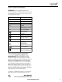
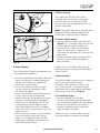
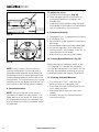
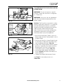
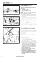
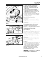
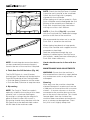
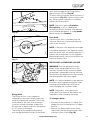
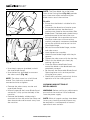
®
210mm TCT Multipurpose
Mitre / Table Saw
Original
Instructions
Read instructions before operating this tool.
16.04.12_V9
www.evolutionfury.com
GB
2
03
www.evolutionfury.com
TABLE OF CONTENTS
GB
EC - Declaration of Conformity
4
Important Information
5
Instruction Manual
12 Month Limited Warranty
5
Read instructions before operating this tool.
General Safety Rules
5
Additional Specific Safety Rules
7
Safety Labels and Symbols
8
Machine Overview
12-13
Operation Mitre Saw
16
Operation Table Saw
21
Maintenance24
Environmental Protection
28
Service Parts Diagram
30
www.evolutionfury.com
3
EC - DECLARATION OF CONFORMITY
We, manufacturer and importer
Evolution Power Tools Ltd.
Venture One
Sheffield
S20 3FR
Declare that the product
Part numbers:
EVOLUTION FURY 6
Evolution: TABLE MITRE SAW
Complies with the essential requirements
of the following European Directives:
2006/42/EC – Machine Directive
2006/95/EC – Low Voltage Directive
2004/108/EC – EMC Directive
2002/95/EC – Restriction of the use of
Certain Hazardous Substances in Electrical
and Electric Equipment
Standards and Technical specifications
referred to:EN 61029-1
EN 61029-2-11
EN 55014-1
EN 55014-2
EN 61000-3-2
EN 61000-3-3
Authorised by
Mr. Matthew J Gavins
Managing Director
31st January 2012
All documentation is held on file at
the above address and is available, on
request for review.
This manual was originally written in
English.
4
www.evolutionfury.com
IMPORTANT
Please read these operating and safety
instructions carefully and completely.
For your own safety, before using this
equipment check that the fitted plug and
voltage are correct, and that all handles and
parts are firmly secured. If you are uncertain
about any aspect of using this equipment,
please contact our Technical Helpline.
Technical Helpline UK 0870 609 2297
EVOLUTION TABLE MITRE SAW
Congratulations on your purchase of an
Evolution Power Tools Table Mitre Saw.
Please complete your product registration
online to validate your machine’s warranty
period and ensure prompt service if needed.
We sincerely thank you for selecting a
product from Evolution Power Tools.
12 MONTH LIMITED WARRANTY.
Evolution power tools reserves the right
to make improvements and modifications
to design without prior notice.
Evolution Power Tools will, within twelve
(12) months from the original date of
purchase, repair or replace any goods
found to be defective in materials or
workmanship. This warranty is void if the
tool being returned has been used to cut
materials beyond the recommendations in
the Instruction Manual or if the machine
has been damaged by accident, neglect, or
improper service. This warranty does not
apply to machines and / or components
which have been altered, changed, or
modified in any way, or subjected to use
beyond recommended capacities and
specifications. Electrical components
are subject to respective manufacturers’
warranties. All goods returned defective
shall be returned prepaid freight to Evolution
Power Tools. Evolution Power Tools reserves
the right to optionally repair or replace it with
the same or equivalent item. There is no
warranty – written or verbal – for saw blades.
In no event shall Evolution Power Tools be
liable for loss or damage resulting directly or
indirectly from the use of our merchandise
or from any other cause. Evolution Power
Tools is not liable for any costs incurred
on such goods or consequential damages.
No officer, employee or agent of Evolution
Power Tools is authorized to make oral
representations of fitness or to waive any
of the foregoing terms of sale and none
shall be binding on Evolution Power Tools.
Questions relating to this limited warranty
should be directed to the company’s head
office, or call the appropriate Helpline
number.
GENERAL SAFETY RULES
WARNING: When using electric tools,
basic safety precautions should always be
followed to reduce the risk of fire, electric
shock and personal injury.
Please read all of these instructions
before attempting to operate this
machine. Save this manual for future
reference.
1. Keep work area clear. Cluttered work
areas invite accidents.
2. Consider work area environment. Do
not expose tools to rain. Do not use tools
in damp or wet locations. Keep work area
well lit. Do not use tools in the presence of
flammable liquids or gases.
3. Guard against electric shock. Avoid
body contact with earthed or grounded
surfaces (e.g. pipes, radiators, ranges,
refrigerators).
4. Keep other people away. Do not let
others, especially children, come close to the
work, and touch the tool or the extension
lead. Keep them away from the work area.
5. Store idle tools. When not in use, tools
should be stored in a dry locked-up place,
out of reach of children.
6. Do not force the tool. It will do the job
better and safer at the rate for which it was
intended
7. Use the right tool. Do not force small
tools to do the job of a heavy duty tool. Do
www.evolutionfury.com
5
not use tools for purposes not intended; for
example do not use circular saws to cut tree
limbs or logs.
8. Dress properly. Do not wear loose
clothing or jewellery, they can be caught
in moving parts. Non-skid footwear is
recommended when working outdoors.
Wear protective hair covering to contain long
hair.
9. Use protective equipment. Use safety
glasses. Use face or dust mask if working
operations create dust.
10. Connect dust extraction equipment.
If the tool is provided for the connection of
dust extraction and collection equipment,
ensure these are connected and properly
used.
11. Do not abuse the cord. Never yank
the cord to disconnect it from the socket.
Keep the cord away from heat, oil and sharp
edges.
12. Secure work. Where possible, use
clamps or a vice to hold the work. It’s much
safer than using your hand.
13. Don’t over reach. Keep proper footing
and balance at all times.
14. Maintain tools with care. Keep
cutting tools sharp and clean for better and
safer performance. Follow instructions for
lubricating and changing accessories. Inspect
tool cords periodically and, if damaged, have
them repaired by an authorised service
facility. Inspect extension cord periodically
and replace immediately if damaged. Keep
handles dry, clean and free from oil and
grease.
15. Disconnect tools. When not in use,
before any servicing and when changing
accessories such as blades, bits, cutters,
disconnect tool from the power source
16. Remove adjusting keys and spanners.
Form the habit of checking to see the keys
and adjusting spanners are removed from
the tool before turning it on.
17. Avoid unintentional starting. Ensure
switch is in “off” position when plugging in.
18. Use outdoor extension leads. When
the tool is used outdoors, use only extension
cords intended for outdoor use and so
marked.
6
19. Stay alert. Watch what you are doing,
use common sense and do not operate the
tool when you are tired.
20. Check damaged parts. Before further
use of tool, it should be carefully checked
to determine that it will operate properly
and perform the intended function. Check
for alignment of moving parts, mountings
and any other components that may affect
its operation. A guard or other part that is
damaged should be properly repaired or
replaced by an authorised service centre
unless otherwise indicated in this instruction
manual. Have defective switches replaced by
an authorised service centre. Do not use the
tool if the switch does not turn it on and off.
21. WARNING. The use of any
accessory or attachment other than one
recommended in this instruction manual
may present a risk of personal injury.
22. Have your tool repaired by a qualified
person. This electric tool complies with
relevant safety rules. Repairs should only be
carried out by qualified persons using original
spare parts. Otherwise this may result in
considerable danger to the user.
HEALTH ADVICE
WARNING: When drilling, sanding, sawing
or grinding, dust particles will be produced.
In some instances, depending on the
materials you are working with, this dust can
be particularly harmful to you (e.g. lead from
old gloss paint).You are advised to consider
the risks associated with the materials you
are working with and to reduce the risk of
exposure.
You should:
•
•
Work in a well-ventilated area.
Work with approved safety equipment,
such as dust masks that are specially
designed to filter microscopic particles.
www.evolutionfury.com
ADDITIONAL SAFETY INSTRUCTIONS
FOR YOUR TABLE MITRE SAW
WARNING: Be sure to read and
understand all instructions. Failure to
follow all instructions listed below may
result in electric shock, fire and/or serious
personal injury.
1. Know your power tool. Read operator’s
manual carefully. Learn the applications and
limitations, as well as the specific potential
hazards related to this tool.
2. Always wear safety glasses or eye
shields when using this mitre saw.
Everyday eyeglasses have only impactresistant lenses; they are not safety glasses.
3. Always protect your lungs. Wear a face
mask or dust mask if the operation is dusty.
4. Always protect your hearing. Wear
hearing protection during extended periods
of operation.
5. Inspect the machines power cord regularly
and if damaged have it repaired or replaced.
Always be aware of the cords location.
6. Always check for damaged parts.
Before further use of the tool, a guard
or other part that is damaged should be
carefully checked to determine if it will
operate properly and perform its intended
function. Check for misalignment or binding
of moving parts, breakage of parts, and
any other condition that may affect the
tool’s operation. A guard or other part that
is damaged should be properly repaired or
replaced at a qualified service centre. Keep
guards in place and in working order.
7. Do not abuse the cord. Never use the
cord to carry the tool or pull the plug
from the outlet. Keep cord away from
heat, oil, sharp edges or moving parts.
Replace damaged cords immediately.
Damaged cords increase the risk of electric
shock.
8. Always make sure that your extension
cord is in good condition. When using an
extension cord be sure to use one that is
heavy enough to carry the current that your
tool will draw. An undersized cord will cause
a drop in line voltage, resulting in loss of
power and overheating.
9. Do not use the tool while tired or under
the influence of drugs, alcohol or any
medication. Following this rule will reduce
the risk of electric shock, fire or serious
personal injury.
10. Save these instructions. Refer to
them frequently and use them to instruct
others who may use this tool. If someone
borrows this tool, make sure they have
these instructions also.
11. When the correct blade to cut the
material has been fitted, this saw is
recommended for cutting steel and
ferrous metals, aluminium and nonferrous metals, wood, and plastic only.
12. Do not use saw blades with High
Speed Steel (HSS) or blades that are
damaged or deformed.
13. Replace the table insert when worn.
14. Use only saw blades recommended
by the manufacturer and which are the
exact bore and diameter required for this
machine.
15. Connect your mitre saw to a dust
collecting device (O.D.Ø32mm) when
sawing material likely to cause dust.
16. Select saw blades in relation to the
material to be cut. Use only genuine
Evolution or Evolution recommended
accessories.
17. Check the maximum depth of cut.
18. When sawing long work pieces,
always use extra support to provide
better support, and use clamps or other
clamping devices.
19. Make sure the operator is adequately
trained in the use, adjustment and
operation of the machine.
20. Provide for adequate room lighting at
your workplace or for adequate lighting
of the immediate work area.
21. Refrain from removing any cut-offs
or other parts of the workpiece from
the cutting area whilst the machine is
running and the saw head is not in the
rest position. Never reach around the saw
blade. Turn off tool and wait for saw blade to
stop before moving workpiece or changing
settings.
www.evolutionfury.com
7
22. Never stand on this tool. Serious
injuries could occur if this tool tips over and
you come into contact with the saw blade.
23. Reduce the risk of unintentional
starting. Make sure switch is in off position
before plugging in.
25. Do not use the saw without the guards
in position, especially after a mode change,
and to keep guards in good working order
and properly maintained.
26. The Riving Knife shall not be thicker
than the width of the groove cut by the
saw blade and not thinner than the body
of the blade.
27. Ensure that the arm is securely fixed
when beveling.
28. Always put the push stick into
storage when not in use.
29. Keep the floor area free of loose
material e.g. chips and off cuts.
30. Ensure that the bench saw table is
securely fixed at the chosen height.
31. Ensure that the speed marked on the
saw blade is at least equal to the speed
marked on the saw.
32. Ensure that the upper portion of the
saw blade is completely enclosed in mitre
saw mode.
33. Refrain from removing any off cuts
or other parts of the workpiece from
the cutting area whilst the machine is
running and the saw head is not in the
rest position.
34. The saw shall not be used for slotting
(stopped groove).
35. Always clamp the workpiece to the
saw table in mitre saw mode. Ensure
before each cut that the machine is stable.
WARNING: The operation of any table mitre
saw can result in foreign objects being
thrown into your eyes, which can result in
severe eye damage. Before beginning power
tool operation, always wear safety goggles
or safety glasses with side shield and a full
face shield when needed.
WARNING: If any parts are missing, do not
operate your table mitre saw until the missing
parts are replaced. Failure to follow this rule
could result in serious personal injury.
8
ADDITIONAL SAFETY ADVICE
CARRYING YOUR TABLE MITRE SAW
Safety Advice
1. Although compact, this saw is heavy. To
reduce the risk of back injury, get competent
help whenever you have to lift the saw.
2. To reduce the risk of back injury, hold the
tool close to your body when lifting. Bending
your knees so you can lift with your legs, not
your back. Lift by using the handhold areas
at each side of the machines base.
3. Never carry the Table Mitre Saw by the
power cord. Carrying the tool by the power
cord could cause damage to the insulation
or the wire connections resulting in electric
shock or fire.
4. Before moving the saw tighten the mitre
and bevel locking screws to guard against
sudden unexpected movement.
5. Lock the Cutting Head in its lowest position.
Ensure that the Cutting Head Locking Pin is
completely engaged in its socket.
WARNING: Do not use the blade guard as
a ‘lifting point’. The power cord must be
removed from the power supply before
attempting to move the machine.
•
•
•
•
Lock the Cutting Head in the down
position using the Cutting Head locking
pin.
Loosen the Mitre Angle Locking Screw.
Turn the table to either of its maximum
settings.
Lock the table in position using the
Locking Screw.
Use the two carry handle cut-outs
machined into either side of the
machine base, to transport the
machine.
Place the saw on a secure stationary
work surface and check the saw over
carefully.
Check particularly the operation of all the
machines safety features before attempting
to operate the machine.
www.evolutionfury.com
SAFETY LABELS & SYMBOLS
WARNING: Do not operate machine if
warning and/or instruction labels are missing
or damaged. Contact Evolution Power Tools
for replacement labels.
Symbol
Description
V
Volts
A
Amperes
Hz
Hertz
min-1
Speed
~
Alternating Current
No
No Load Speed
Wear Safety
Goggles
Wear Ear Protection
Do Not Touch
Wear Dust Protection
Restriction
of Hazardous
Substances Directive
CE certification
Waste electrical and
electronic equipment
Only use genuine Evolution replacement
saw blades. Unauthorized blades may
be dangerous! Keep saw blades securely
fastened. Check the blade flanges for debris
before installing any new blade. Do not use dull,
broken or damaged blades. Check the blade
regularly for condition and wear. A damaged or
worn blade should be replaced immediately.
Beware of ejecting chips as they may be HOT.
Always make provision for the safe handling of
excess material. Keep machine base and rotary
table free from dirt and other debris.
To obtain an additional copy of your Manual,
please contact Evolution Power Tools at:
UK 0870 609 2297
WEBwww.evolutionpowertools.com
www.evolutionfury.com
9
FURY 6 TABLE MITRE SAW SPECIFICATION
Designed to cut:
Mild Steel
Wood
Aluminium
Plastic
Technical Data
Motor (230V ~ 50 Hz) (Watts)
RPM No Load (min-1):
Recommended Maximum Duty Cycle (Minutes):
Weight (kg):
1200
3500
30
9.45
Blade Dimensions - Multipurpose TCT
Diameter (mm):
Number of Teeth: Bore Diameter (mm):
Kerf thickness (mm):
Maximum Cutting Capacity - Mild Steel
Maximum Cutting Capacity (Wood) Mitre Saw Configuration
At 900 mitre x 900 bevel (mm):
At 450 mitre x 900 bevel (mm):
At 450 mitre x 450 bevel (mm):ww
210
20
25.4
1.7
3 mm
115 x 55
65 x 55
40 x 25
Maximum Cutting Capacity (Wood) Table Saw Configuration
Maximum cutting depth (mm):
32 mm
Noise and Vibration Data
Sound pressure level:
Sound power level:
Vibration level:
106.3dB(A) K=3dB(A)
119.3dB(A) K=3dB(A)
2.5 m/S2 K =1.5dB(A)
The declared vibration total value has been measured in accordance with a standard test
method and may be used for comparing one tool with another.
The declared vibration total value may also be used in a preliminary assessment of exposure.
WARNING: The vibration emission during actual use of the power tool can differ from the
declared total value depending on the ways in which the tool is used. The need to identify
safety measures and to protect the operator are based on an estimation of exposure in the
actual conditions of use (taking account of all parts of the operating cycle, such as the times
the tool is switched off, when it is running idle, in addition to trigger time).
10
www.evolutionfury.com
Assembly
Your Evolution Power Tools saw is shipped
complete. Remove all contents from the
box and inspect to ensure no damage was
incurred during shipping, and that the items
listed below are included.
Items Supplied
DESCRIPTION
Quantity
Instruction Manual
1
Hold Down Clamp
1
Push Stick
1
Pin Spanner (Blade Change)
1
Hex Key 6mm (Blade Change)
1
Hex Key 4mm
(Riving Knife Adjustment)
1
Multi-Purpose Blade (Fitted)
1
Rip Fence/Bevel Guide Assembly
1
Auxiliary Lower Blade Guard
(Fitted)
1
Dust Bag Adaptor Tube
1
Workpiece Supports
2
Rear Stabilising Arms
2
Additional Accessories
In addition to the standard accessories
supplied with this machine, other
accessories are available to improve its
performance, these include the following
items:
Specialist cutting blades – use only
Evolution Blades with this machine.
Additional accessories can be obtained by
contacting your local dealer (or Evolution
Power Tools).
Dust Bag as an optional accessory
www.evolutionfury.com
11
LH VIEW OF FURY 6 MITRE SAW CONFIGURATION
11
1
12
3
4
5
9
2
8
6
10
7
1. CUTTING HANDLE
2. ROTARY TABLE
3. RETRACTABLE LOWER BLADE GUARD
4. BLADE
5. BEVEL LOCKING LEVER (Back of the machine)
6. MITRE ANGLE LOCKING SCREW
7. MITRE ANGLE SCALE
12
8. FENCE
9. HOLD DOWN CLAMP
10. STABILISING ARMS (X2 Back of machine)
11. CUTTING HEAD RELEASE LEVER
12. TABLE HEIGHT ADJUSTING SCREW
www.evolutionfury.com
LH VIEW OF FURY 6 TABLE SAW CONFIGURATION
10
7
6
4
1
3
2
5
9
8
1. ON/OFF TRIGGER SWITCH (Inside handle)
2. ON/OFF LATCHING SWITCHES
3. CUTTING HANDLE
4. TABLE TOP
5. AUXILLIARY LOWER BLADE GUARD
6. UPPER BLADE GUARD
7. RIP FENCE
8. PUSH STICK
9. MOUNTING HOLE
(2 at the front and 2 under the stabilising arms)
10. CUTTING HEAD LATCHING PIN
(Not shown in this view)
www.evolutionfury.com
13
GETTING STARTED
1
WARNING: ALWAYS DISCONNECT
THE SAW FROM THE POWER SOURCE
BEFORE MAKING ANY ADJUSTMENTS.
Refer to the “Service Parts Diagram”. Install
a blade as detailed in the “Installing or
Removing the Blade” section.
Note: We recommend that the operator
reads the ‘Important Information’ sticker
applied to the table of the Fury6. Practicing
and becoming familiar with the procedures
outlined on this sticker will make subsequent
adjustments/assembly or configuring fairly
straightforward.
PERMANENTLY MOUNTING THE FURY6
TABLE/MITRE SAW (Fig. 1)
WARNING: To reduce the risk of injury from
unexpected saw movement, place the saw
in the desired location either on a workbench
or other recommended leg set. The base of
the saw has four holes to mount the mitre
saw. If the saw is to be used in one location,
permanently fasten it to the workbench or
leg set using appropriate bolts with lock
washers and nuts.
Note: When permanently mounting the
Fury6 we recommend that the four (4)
rubber feet located underneath each of the
mounting holes are removed and stored
safely for possible future use.
1. Tighten the mitre and bevel locks.
2. Position the saw so other people cannot
stand behind it. Thrown debris could injure
people in its path.
3. Place the saw on a firm, level surface
where there is plenty of room for handling
and properly supporting the workpiece.
4. Support the saw so that the table is level
and the saw does not rock.
5. Bolt or clamp the saw to its support.
14
M8 x 75
2
3
4
5
6
7
8
9
Fig. 1
1) Hex headed bolt M8 X 75
2) Spring washer
3) Flat washer
4) Mitre saw base
5) Workbench
6) Flat washer
7) Spring washer
8) Hex nut
9) Lock nut
THESE ITEMS
ARE NOT
SUPPLIED
For Portable Use (Fig. 2)
Note: The Fury6 is designed to be a highly
portable machine.
For portable use the Fury6 must be fitted
with the two (2) rear Stabilising Arms.
To fit the Stabilising Arms:
• Remove the cross head machine
screws from the two (2) rear mounting
positions.
• Attach the Stabilising Arms with the
machine screws, two per arm and
tighten securely.
Note: The Stabilising Arms are fitted with
rubber feet. The base of the Fury6 is also fitted
with four (4) identical rubber feet positioned
underneath the mounting holes in the base.
When used as a portable machine the six (6)
rubber feet provide the security and stability
necessary for safe operation.
www.evolutionfury.com
Note: When the machine is re-positioned
the operator should ensure that none of
the rubber feet become detached from
the machine. The rubber feet can, in some
circumstances, stick to some surfaces due
to vacuum suction.
If any of the rubber feet become detached or
damaged they must be replaced.
DUST BAG
Fig. 2
A Dust Bag (not supplied) can be fitted
to the extraction port at the rear of the
machine. (Fig. 3a & 3b)
• Push the adaptor tube into the extraction
port at the rear of the machine.
• Slide the Dust Bag onto the adaptor tube
ensuring that the spring clip grips the tube
holding the Dust Bag securely in place.
Fig. 3a
Note: For operational efficiency empty
the Dust Bag when it becomes 2/3 full.
Dispose of the contents of the Dust Bag in
an environmentally responsible way. It may
be necessary to wear a dust mask when
emptying the Dust Bag
WARNING: DO NOT USE A DUST BAG
WHEN CUTTING STEEL.
Fig. 3b (Dust bag, not supplied)
www.evolutionfury.com
15
TO CONFIGURE THE FURY6 FOR USE AS
A MITRE SAW
WARNING: Only carry out this procedure
with the machine disconnected from the
power source.
Fig. 4
Fig. 5
Caution: The Fury6 has many built in safety
features and safety interlocks. It is important
that the following instructions, and those
found on the label attached to the machine
table are read, understood and acted
upon. Failure to carry out the configuration
procedure could result in damage to the
machine and/or injury to the operator.
• Loosen the table height adjustment
screw. (Fig.4)
• Raise the table top to its upmost position
and tighten the height adjustment screw.
(Fig. 5)
• Slightly push down on the Cutting Head Handle.
• Pull out the Cutting Head Latching Pin
and allow the Cutting Head to rise to its
upmost position. (Fig. 6)
• Remove the Auxiliary Lower Blade Guard
and store safely for future use.
The Fury6 is now ready to use as a
Mitre Saw. (Fig. 7)
Fig. 6
Fig. 7
16
www.evolutionfury.com
Workpiece Supports can be very useful in
providing extra support for long workpieces
when using the Fury6 in Mitre Saw
configuration.
HOLD DOWN CLAMP (Fig. 9)
A Hold Down clamp is supplied with the Fury6.
Two sockets (one on either side) are
incorporated into the rear of the machines
fence.
• Fit the pillar of the clamp into the socket
that best suits the cutting application,
ensuring that it is pushed fully down.
• Tighten the fence thumbscrew to lock the
pillar of the Hold Down Clamp into the
fence socket.
• Put the workpiece onto the rotary table
and against the fence.
•Adjust the Hold Down Clamp so that
it securely holds the workpiece to the
rotary table.
• Before attempting any cutting check to
ensure that the clamp does not interfere
with the blade path as the Cutting Head
is lowered.
Fig. 8
Fig. 9
OPERATING INSTRUCTIONS
MITRE SAW CONFIGURATION
WORKPIECE SUPPORTS (Fig. 8)
Workpiece supports can be fitted to both
sides of the machine base if required.
• Loosen the relevant Workpiece Retaining
Screw located in a socket at the top front
of the machine base.
• Insert the Workpiece Support into the
holes machined in the base.
Note: The Workpiece Support should be
pushed ‘fully home’ into the machine base.
Correct installation will require approximately
65mm of the Workpiece Support to slide into
the machine base.
• Fasten the Workpiece Support into the
base by tightening the Retaining Screw.
WARNING: It is important that the operator
is adequately trained in the use, adjustment
and operation of the machine, and has read
the Instruction Manual before commencing
operations.
Note: We recommend that when the
Fury6 is being used as a Mitre Saw, the
complete Fence Assembly is removed from
the machine as stored safely for future use.
1. Releasing the Cutting Head
Note: When configured in Mitre Saw
mode the Cutting Head will be automatically
locked in its upper position with the
Retractable Lower Blade Guard completely
covering the blade teeth.
www.evolutionfury.com
17
2. Preparing to make a cut
• Avoid awkward operations and hand
positions where a sudden slip could cause
fingers or hands to move into the blade.
• Cut only one workpiece at a time.
• Clear everything except the workpiece and
related support devices away from the
blade before commencing operations.
Fasten the workpiece using clamp(s) to
hold the workpiece securely to the table
and fence.
280mm
No-Hands Zone
3. Body and Hand position (Fig. 10)
No-Hands Zone
Fig. 10
B
A
Fig. 11
4. The Mitre Saw On/Off Trigger Switch
Operation (Fig. 11-A)
To release the Cutting Head press and hold
the Cutting Head Release Lever.
Gently press down on the Cutting Head
Handle to lower the Cutting Head. The
operation of the Retractable Lower Blade
Guard is automatic.
Note: We recommend that when the
machine is not in use the Cutting Head
is locked in its down position, with the
Auxiliary Lower Blade Guard correctly
installed and the Cutting Head Latching Pin
fully engaged in its socket.
18
• Never place hands within the ‘no hands
zone’ (at least 150mm away from the
blade). Pictograms on the machines
rotary table are provided as an aid to safe
working practices. Keep hands away from
the path of the blade.
• Hold the workpiece firmly to the fence to
prevent any movement. Use a Hold Down
Clamp if possible but check that it is
positioned that it does not interfere with
the path of the blade or other moving
machine parts.
• Before attempting a cut, make a ‘dry run’
with the power off so that you can see
the path of the blade.
• Keep hands in position until the ON/OFF
trigger has been released and the blade
has completely stopped.
The On/Off Switch is a non-latching trigger
type switch which is ergonomically located
on the inside of the Cutting Head Handle.
Operate the switch to turn on the machines
motor. Release the switch to turn off the
machines motor.
Note: The Cutting Head cannot be lowered
until the Cutting Head Release Lever is
operated. (Fig. 11-B) The Blade will remain
covered by the retractable guard until the
Cutting Head is released. Operation of the
Retractable Guard is automatic.
www.evolutionfury.com
6. Mitre Cutting
Any angle from 45 0 left to 45 0 right is
available, and a protractor scale can be
found to the front of the Rotary Table.
Positive stops are provided for every 5 0 of
angular movement.
Note: The rotary table must always be locked
into position with the Mitre Angle Locking
Screw even if a positive stop is selected.
Fig. 12
To select a Mitre Angle:
• Loosen the Mitre Angle Locking Screw.
(Fig.12) This is found at the front RH side
of the table near the 30 0 index mark.
• Turn the Rotary Table to the required
angle. To aid setting, an index mark is
machined into the table just in front of the
table insert.
• Tighten the Mitre Angle Locking Screw
securely when the desired angle has
been selected.
Fig. 13
5. Chop Cutting
The Cutting Head is gently pushed down to
cut through the workpiece.
A Mitre Cut can now be made using the
same techniques as previously described in
Chop Cutting.
7. Bevel Cutting
• Place the workpiece on the Rotary Table and
against the fence in the desired position.
Secure with clamp(s) as appropriate.
• Grasp the Cutting Handle.
• Turn on the motor using the trigger
switch and allow the blade to reach
full operating speed.
• Press and hold the Cutting Head Release
Lever to release the Cutting Head.
• Gently lower the Cutting Head to its lowest
position, cutting through the workpiece.
• After the cut is completed, turn off the
motor by releasing the trigger switch.
Allow the blade to come to a complete
stop. Allow the Cutting Head to rise to its
upper position.
• Only remove your hands or the workpiece
from the machine when the Cutting
Head is in its upper position with the
blade teeth completely covered by the
Retractable Blade Guard.
The Cutting Head can be set at any angle up
to 45 0 to the Left Hand side only.
The Bevel Locking Lever is found at the
rear of the machine. A protractor guide
and pointer are incorporated into the bevel
mechanism to aid setting. (Fig.13)
To set a Bevel Angle:
• Loosen the Bevel Lock Handle
• Tilt the Cutting Head to the desired angle.
Use the protractor guide to aid with setting.
• Ensure that the Bevel Lock Handle is
securely tightened when the desired
angle has been achieved.
A Bevel Cut can now be made using the
same techniques as previously outlined.
www.evolutionfury.com
19
To adjust the fence:
• Loosen the thumbscrew. (Fig 14)
• Slide the upper portion of the fence to
the required position and tighten the
thumbscrew.
• Lower the Cutting Head to check the path
of the blade. Ensure there is no interference
with any other parts of the machine.
9. Compound Cutting
Fig. 14
A Compound Cut is a combination of a Mitre
Cut and Bevel Cut.
• Set the Mitre Angle required as previously
described.
• Set the Bevel Angle as previously described.
• Ensure the tightness of all adjustment/
locking screws, and conduct a ‘dry run’ to
check the path of the blade.
• Make the cut as previously described.
10. Cutting Bowed Material (Fig 15)
Fig. 15
Note: Always make a ‘dry run’ with the
machine switched ‘off’ so that the path of
the blade can be checked. Some Bevel and
Compound Cuts may require the Hold Down
Clamp to be positioned to the RH side of the
Cutting Head. This may be necessary to avoid
interference with the blade and other parts of
the machine as the Cutting Head is lowered.
8. Fence Adjustment
Note: The left hand side of the fence is
provided with additional adjustments. The
upper portion of the fence can slide to the
left to provide clearance for the blade. This
may be necessary when acute bevel angles
are selected.
20
Before cutting any workpiece, check to see
if it is bowed. If it is bowed the workpiece
must be positioned and cut as shown. Do not
position the workpiece incorrectly or cut the
workpiece without the support of the fence.
11. Clearing Jammed Material
• Turn mitre saw “OFF” .and allow the
blade to come to a complete halt.
• If possible allow the Cutting Head to rise
to its upper position.
• Unplug the Mitre Saw from the mains
supply.
• Carefully remove any jammed material
from the machine.
www.evolutionfury.com
TO CONFIGURE THE FURY6 FOR USE AS
A TABLE SAW
WARNING: Do not cut metal or metallic
materials when the machine is configured
as a Table Saw.
Fig. 16
WARNING: Only carry out this procedure
with the machine disconnected from the
power supply.
Caution: The Fury6 has many built in safety
features and safety interlocks. It is important
that the following instructions, and those
found on the label attached to the machine
table are read, understood and acted
upon. Failure to carry out the configuration
procedure could result in damage to the
machine and/or injury to the operator.
Fig. 17
Fig. 18
• Ensure that the Rotary Table is set at 0 0
Mitre angle and the Cutting Head is set at
0 0 Bevel angle.
• Position the Auxiliary Lower Blade Guard
on the Rotary Table over the table insert
and straddling the Fence. (Fig. 16)
• Lower the Cutting Head to the fully down
position, ‘capturing’ the Lower Auxiliary
Blade Guard. Push the Cutting Head
Latching Pin into its socket. (Fig. 17)
• Loosen the Table Height Adjustment
Screw (Fig.18) and lower the table to its
lowest position.
• Tighten the Height Adjustment Screw.
The Fury6 is now ready to use as a
Table Saw.
www.evolutionfury.com
21
FENCE ASSEMBLY (Fig. 19)
The Fence Assembly consists of two (2)
main parts:
• The Angle Gauge.
• The Rip Fence Face Plate.
height
Fig. 19
Fig. 20
Note: The ‘T’ slot in the Rip Fence Face
Plate is not centrally located.
• Slide the Rip Fence Face Plate onto the
two (2) mounting screws found on the
Angle Plate.
• Ensure that the wider (20mm) portion of
the Fence Face is downwards and will lie
on the saw table when in use.
The Angle Plate can now be slid into the
Rip Fence channel found at the front of the
machine table. (Fig. 20)
Slide in from the Right Hand side ensuring
that the Locking Clamp engages correctly
with the front face of the Rip Fence channel.
FENCE ASSEMBLY AS A RIP FENCE
To use the Fence Assembly as a Rip Fence
the Face Plate must be accurately aligned
with the blade.
WARNING: Only carry out this procedure
with the machine disconnected from the
power supply.
Fig. 21
22
To Align the Rip Fence:
• Ensure that the table is at its lowest
setting (see Fig. 23a &23b)
• Set the Angle Gauge to an indicated 90 0.
• Slide the Fence Assembly up to the blade,
raising the Blade Guard by hand so that the
Face Plate rests alongside the blade and
underneath the Blade Guard. (Fig.21)
Gently tighten the Angle Gauge Locking
Clamp Screw to lock the Assembly into
the Rip Fence channel.
• Check that the Face Plate is in exact
alignment with the blade.
• If adjustment is required, loosen slightly
the Angle Clamping Screw and adjust
the Angle Gauge until exact alignment is
achieved.
www.evolutionfury.com
• Tighten the Angle Clamping Screw.
• Adjust the Angle Gauge Pointer if
necessary to point exactly to the 90 0
index mark.
• Use a #2 Phillips Head screwdriver to
loosen the Angle Pointer fixing screw.
(Fig. 22) Adjust the pointer to suit and
then retighten the fixing screw.
• Loosen the Angle Clamp Locking Screw
to allow the Assembly to slide along the
Rip Fence channel.
Basic Table Saw Operations
WARNING: Do not cut metal or metallic
materials when the machine is configured
as a Table Saw.
Fig. 22
WARNING: Never attempt freehand cuts
on this machine. Always use a correctly
adjusted Rip Fence to minimise the
possibility of the blade binding and kickback.
1. Adjusting the Table Height
(Fig. 23a &23b)
Fig. 23a
The height of the Table above the machines
motor can be adjusted. This enables your
Fury6 to mimic the rise and fall facility found
on many conventional table saws. The
cutting depth of the blade can thereby be
adjusted from 0mm to 32mm.
WARNING: Only adjust the height of the
table with the machine disconnected from
the mains power supply.
Fig. 23b
To adjust:
• Loosen the Height Adjustment Screw and
adjust the table height so that the saw
blade protrudes through the table by the
required amount. Retighten the screw.
We recommend that the saw blade
protrudes through the material to be
cut by approximately 3mm.
WARNING: This machine is not suitable for
cutting rebates or stopped grooves.
www.evolutionfury.com
23
Note: Check that the Rip Fence is locked
in position and is parallel to the saw blade.
Check that the riving knife is properly
aligned with the saw blade.
When ripping small section material a Push
Stick should be used to feed/guide the final
300mm of the material past the blade. A
Push Stick should always be used when
making cuts of less than 300mm.
Note: A Push Stick (Fig. 25) is provided
with the Fury6 and has a dedicated storage
position to the front of the machine.
Fig. 24
We recommend that when not in use the
Push Stick is stored on the machine.
When ripping long boards or large panels
always use a remote work support or enlist
competent trained help.
Feed the workpiece through the saw
keeping it indexed against the Rip Fence.
Use smooth, steady pressure and employ a
Push Stick when necessary.
Fig. 25
Note: A workshop dust extraction device
can be connected to the extraction port
found at the rear of the machine if required.
Hands should never be in line with the
blade.
MAINTENANCE AND ADJUSTMENTS
2. Table Saw On/Off Switches (Fig. 24)
The On/Off Switch is a two (2) button
latching type. The buttons are located on the
Front Left Hand side of the Cutting Handle.
• Push the Green (I) button to start the motor.
• Push the Red (O) button to stop the motor.
3. Rip cutting
Note: The Fury6 in Table Saw mode is
optimally suited for the cutting of thin sheet
material such as laminate flooring etc.
Rip cutting is cutting along the length of a
piece of material rather than across it.
Rip cutting should always be done with the
Rip Fence set to the desired width and on
the RH side of the machines table.
24
WARNING: Ensure that the machine is
disconnected from the mains supply before
any maintenance tasks or adjustments are
attempted.
Cleaning
After each use the machine should be
cleaned. Remove all sawdust etc from the
visible parts of the machine with a vacuum
cleaner. A vacuum cleaner can also be
connected to the machine dust extraction
port at the rear of the machine. This should
remove debris from the inside of the
machine. Never use solvents to clean plastic
parts, as solvents can damage them. Clean
only with a soft slightly damp cloth.
www.evolutionfury.com
teeth and the edge of the Riving Knife is
approximately 3-5mm. (Fig.26)
To adjust the Riving Knife loosen the two (2)
fixing screws (Fig. 27) slightly using an allen
key. When correct alignment is achieved
tighten the fixing screws.
Note: Use only a genuine Evolution
Riving Knife, as this is a dedicated
component for this machine. Non genuine
parts could be dangerous. If in any doubt,
please contact the Helpline.
Fig. 26
Push Stick
A plastic push stick is provided with the
machine. When not in use store the push
stick on the machine.
Note: If the push stick becomes damaged
it should be replaced. If the operator makes
their own push stick, we recommend that it
follows the same pattern as that supplied.
Replacement push sticks are available from
Evolution Power Tools.
Fig. 27
INSTALLING or REMOVING a BLADE
WARNING: Only use genuine Evolution
blades which are designed for use in this
machine. Ensure that the maximum speed
of the blade is compatible with the machine.
Only perform this operation with the machine
disconnected from the mains supply.
Note: It is recommended that the operator
considers wearing protective gloves when
handling the blade during installation or
when changing the machines blade.
Fig. 28
Riving Knife
The Riving Knife is a very important
component and comes factory fitted and
correctly aligned and adjusted. The Riving
Knife prevents the work from binding as
it passes through the blade. Inspect the
Riving Knife at regular intervals and replace
it if it is worn or damaged.
The Riving Knife should be adjusted so
that the gap between the tips of the blade
Note: The blade is a very precise fit
within the Fury6 machine. Be patient and
methodical when changing the blade.
To change a blade:
• Ensure that the machine is in Mitre Saw
Mode with the Cutting Head in its upper
position.
• Release the Retractable Lower Guard
Operating Lever by removing and safely
storing its pivot screw. (Fig. 28)
www.evolutionfury.com
25
Note: The 5mm blade slot at the lower
front of the Cutting Head (Fig. 30) provides
extra clearance when manoeuvring the
blade into or out of the machine.
Fig. 29
Fig. 30
• Use the pin spanner (provided) to hold
the outer blade flange.
• Use the hex key (provided) to unscrew
the arbor screw. (Fig. 29)
Note: The arbor screw has a Left Hand
thread. Turn clockwise to undo and
counterclockwise to tighten.
• Remove the arbor screw, washer and
outer blade flange.
• Manually operate the Lower Blade Guard
and retract it fully up into the body of the
machine
• Remove the blade by withdrawing it
outwards to clear the end of the arbor and
then downwards and forwards away from
the machine.
26
To refit:
• Ensure that the blade is suitable for this
machine.
• Ensure that the direction of rotation arrow
on the blade matches the direction of
rotation arrow found on the machines Side
Blade Guard. The blade teeth should always
point downward at the front of the saw.
• Using the blade slot to provide maximum
clearance and access to the machine,
carefully and gently manoeuvre the blade
up into the machine and locate it on the
inner blade flange.
• Reinstall the outer blade flange, washer
and arbor screw.
• Hand tighten the assembly.
• Hold the outer blade flange with the pin
spanner.
• Tighten the arbor screw with the hex key.
• Check that the blade spins freely by
rotating it by hand.
• Close the Retractable Blade Guard
around the blade so the blade teeth are
completely covered.
• Re-connect the Retractable Blade Guard
Operating Lever to its service position
using the pivot screw.
• Check the installation, particularly for the
operation of all the safety guards.
CHECKING AND SETTING OF
BEVEL ANGLES
WARNING: Before making any adjustments
ensure that the machine is disconnected
from the power supply.
Note: While all angular settings have been
factory set, checking and adjustment may
be required as a consequence of normal
operational wear and tear.
www.evolutionfury.com
If adjustment is required:
Note: The Cutting Head will need to be
tilted to gain access to the 0 0 Bevel Stop
Adjustment Screw.
• Loosen slightly the 0 0 Bevel Stop
Adjustment Screw locknut. (Fig. 31)
• Use an Allen Key to turn the Bevel Stop
Screw clockwise or counterclockwise
as required.
• When exact alignment between the
blade and Rotary Table is achieved,
tighten the locknut.
Fig. 31
450 BEVEL ANGLE
The 45 0 Bevel Angle can be checked in a
similar manner to the 0 0 Bevel Angle. An
accurate 45 0 Engineers Set Square (not
supplied) will be required.
Fig. 32
Note: To check and adjust the Bevel
Angles the machine must be in Mitre Saw
configuration.
00 BEVEL ANGLE
At 0 0 Bevel Angle the blade should be
perpendicular and at exactly 90 0 to the
Rotary Table. An accurate engineers square
(not supplied) is needed to check the 0 0
Bevel Angle.
To check:
• Ensure that the Cutting Head is in the
vertical position, against its stop with the
Bevel Pointer indicating 0 0 Bevel Angle.
• Tighten the Bevel Lock Handle.
• Lower the Cutting Head to its lowest
position. The Retractable Lower Blade
Guard will rotate up into the machine.
• The engineers square can now be used to
check the angle between the blade and
the Rotary Table.
To check:
• Ensure that the Cutting Head is tilted to
the 45 0 position, against its stop, with the
Bevel Pointer indicating 45 0 Bevel Angle.
• Tighten the Bevel Lock Handle.
• Lower the Cutting Head to its lowest
position. The Retractable Lower Blade
Guard will rotate up into the machine.
• Use the Engineers 45 0 Set Square to
check the angle of between the blade
and the Rotary Table.
If adjustment is required:
Note: The Cutting Head will need to be
tilted to gain access to the 45 0 Bevel Stop
Adjustment Screw.
• Loosen slightly the 45 0 Bevel Stop
Adjustment Screw locknut. (Fig. 32)
• Use a Hex Key to turn the Bevel Stop
Screw clockwise or counterclockwise
as required.
• When exact alignment between the
blade and Rotary Table is achieved,
tighten the locknut.
www.evolutionfury.com
27
FUSE AND PLUG REPLACEMENT
Should the fuse in the main plug of your
machine need replacing it should always be
replaced with one of identical rating.
Check the voltage given on your machine
matches the supply voltage.
This machine is supplied with a fitted
moulded plug. If you should need to fit a
new plug follows the protocol below.
Fig. 33a
IMPORTANT
The wire in the mains lead are coloured in
accordance with the following code:
Blue --Neutral
Brown --- Live
The wire that is coloured blue must be
connected to the terminal that is marked
with the letter N. The wire that is coloured
brown must be connected to the terminal
that is marked with the letter L.
A 13AMP (BS1363 or BS1363/A) plug must
be used and a 13 AMP fuse must be fitted.
Fig. 33b
FENCE ADJUSTMENT (Fig. 33a & 33b)
ENVIRONMENTAL PROTECTION
The Fence is fastened to the machines
base by two (2) socket head screws, one
on either side. These Screws are located in
elongated holes, which enable the Fence to
be repositioned as required.
Waste electrical products should not be
disposed of with household waste. Please
recycle where facilities exist. Check with your
Local Authority or retailer for recycling advice.
The Fence should be set at exactly 90 0 to a
correctly installed blade.
An accurate Engineers Square (not supplied)
will be required to precisely position the Fence.
To reposition the Fence:
• Set the Rotary Table to 0 0 Mitre Angle.
• Set the Cutting Head to 0 0 Bevel Angle.
• Slightly loosen the two (2) Fence socket
head screws.
• Lower the Cutting Head to its lowest
position.
• Check the alignment of the Fence with
the Blade using the Engineers Square.
• Align the Fence as necessary and then
tighten the socket head screws.
28
www.evolutionfury.com
www.evolutionfury.com
29
30
www.evolutionfury.com
www.evolutionfury.com
31
®
UK ADDRESS:
Evolution Power Tools,
Venture One, Longacre Close, Holbrook
Industrial Estate, Sheffield, S20 3FR
TEL: +44 (0) 114 251 1022
FAX: +44 (0) 114 247 3339