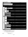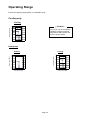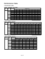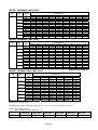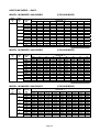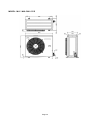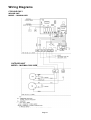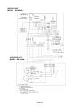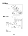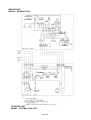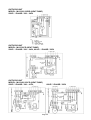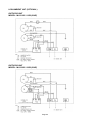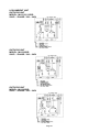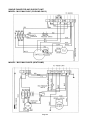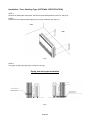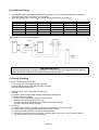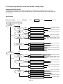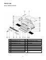
1
MCM - 2004 Ceiling Exposed Split Systems Models: MCM 020 MCM 025 MCM 030 MCM 040 MCM 050 MCM 061 MCM 062 D/DR D/DR D/DR D/DR D/DR C/CR C/CR REGISTERED ISO 9002 ©2004 McQuay International +1 (800) 432-1342 www.mcquay.com Contents Special Features ........................................................................................................... 2 Specifications ................................................................................................................ 3 Noise Level ................................................................................................................... 15 Operation Range .......................................................................................................... 19 Refrigerant Circuit ....................................................................................................... 20 Performance Table ...................................................................................................... 24 Outlines and Dimensions............................................................................................ 37 Wiring Diagrams ......................................................................................................... 41 Special Precautions for R407C .................................................................................. 63 Installation .................................................................................................................... 65 Remote Control Operation Guide .............................................................................. 76 Service and Maintenance ............................................................................................ 79 Troubleshooting .......................................................................................................... 81 Parts List ...................................................................................................................... 87 Note: Installation and maintenance are to be performed only by qualified personnel who are familiar with local codes and regulations, and experienced with this type of equipment, Caution: Sharp edges and coil surfaces are a potential injury hazard. Avoid contact with them. Warning: Moving machinery and electrical power hazards. May cause severe personal injury or death. Disconnect and lock off power before servicing equipment. "McQuay" is a registered trademark of McQuay International. All rights reserved throughout the world. 2003 McQuay International "Bulletin illustrations cover the general appearance of McQuay International products at the time of publication and we reserve the right to make changes in design and construction at any time without notice." Page 1 Special Features Ultra Slim New Stylish Design Profile This unit is contemporary in design and match even the most up to date interior decor. The slim, round profile and compact design of this unit adds a touch of elegance to every decor. No indoor connection pipe and hanger bracket are visible. Ceiling And Floor Convertible With Space Saving Installation This unit is designed for ceiling exposed type and floor exposed type with a very economical and space saving installation. No need renovation to wall or ceiling for ceiling exposed and no foundation work is required for floor exposed installation. This easy to install and ready to operate unit ensure rapid and low installation cost. Strong And Robust The unit is built from strong casing material and robust parts to ensure long lasting reliable service. The drain pan is made from the POLYSTYRENE with a plastic coating on the surface to ensure no leaking and no condensation occur. Friendly Serviceability The air filter, electrical parts, fan and fan motor assembly can all be inspected and replace from bottom of the unit by simply removing the newly designed press in, pull out air intake grille. The POLYSTYRENE drain pan and the heat exchanger coils can remove from the unit easily by remove the bottom panel. Microcomputer Remote Controller The incorporated microprocessor give more accurate control and with the following extra features: • Fan motor speed can be set at high/medium/low and automatic. • Timer on/off - the unit can be pre-set to on and off automatically. • Electronic thermostat - room temperature is precisely controlled resulting in energy saving and increase comfort. • Sleep mode automatically increase set temperature since room temperature is lower at night thus achieving healthy sleep. Wireless Remote Controller The compact wireless remote controller makes it possible to operate the air conditioner anywhere within the room. Auto or Manual Control On Vertical Airflow Direction With auto control, the louver will automatically swing up and down to create an excellent air distribution. You can select your desired horizontal air flow direction by adjusting the vertical grille. Page 2 Specifications Cooling Only (R22) MODEL INDOOR UNIT OUTDOOR UNIT FAN NOMINAL COOLING CAPACITY POWER SOURCE REFRIGERANT / CONTROL AIR FLOW FAN MOTOR kcal/h W Btu/h V/Ph/Hz cfm/cmm 50 Hz 60 Hz W (50/60Hz) A (50/60Hz) COIL FAN COMPRESSOR POWER SOURCE mm/in COMPRESSOR TYPE CAPACITOR - µF 1∅ / < 3∅ > LOCK ROTOR AMPERE - A 1∅ / < 3∅ > RATED RUNNING CURRENT - A 1∅ / < 3∅ > RATED INPUT POWER - W 1∅ / < 3∅ > PROTECTION DEVICE POWER SOURCE FAN TYPE / DRIVE BLADE MATERIAL DIAMETER 2 2 m /ft mm/in mm/in mm/in kg dBA mm/in mm/in mm/in mm/in V/Ph/Hz V/Ph/Hz 50 Hz 60 Hz 50 Hz 60 Hz 50 Hz 60 Hz 50 Hz 60 Hz V/Ph/Hz RATED RUNNING CURRENT (A) RATED OUTPUT POWER (W) RATED INPUT POWER (W) PIPE FIN TUBE MATERIAL DIAMETER THICKNESS MATERIAL THICKNESS ROW FIN PER INCH FACE AREA HEIGHT DIMENSION WIDTH DEPTH WEIGHT MATERIAL CASING THICKNESS FINISHING SOUND PRESSURE LEVEL TYPE SIZE LIQUID GAS PACKING HEIGHT DIMENSION WIDTH DEPTH COIL OUTDOOR UNIT mm/in mm/in FIN INDOOR UNIT TUBE RATED INPUT POWER RATED RUNNING CURRENT MATERIAL DIAMETER THICKNESS MATERIAL THICKNESS ROW FIN PER INCH FACE AREA HEIGHT DIMENSION WIDTH DEPTH WEIGHT SOUND PRESSURE LEVEL ( H / M / L ) ROOM TEMPERATURE CONTROL AIR DISCHARGE OPERATION CONDENSATE DRAIN SIZE AIR FILTER PACKING HEIGHT DIMENSION WIDTH DEPTH mm/in 50 Hz 60 Hz 50 Hz 60 Hz 50 Hz 60 Hz mm/in mm/in mm/in m2/ft2 mm/in mm/in mm/in kg mm/in dBA mm/in mm/in mm/in mm/in mm/in MCM 030D MCM 040D MCM 050D MLC 030B MLC 030C MLC 040C MLC 050C 7056 7560 10080 12600 8204 8792 11723 14654 28000 30000 40000 50000 220 - 240 / 1 / 50, 208 - 230 / 1 / 60 R22 / CAPILLARY TUBE IN OUTDOOR R22 / CAPILLARY TUBE IN INDOOR 730 / 20.7 590 / 16.7 660 / 18.7 1110 / 31.4 1110 / 31.4 4 POLES x 95W 4 POLES x 45W 4 POLES x 95W 4 POLES x 145W 4 POLES x 145W 4 POLES x 95W 4 POLES x 45W 4 POLES x 95W 4 POLES x 140W 4 POLES x 140W 132 / 179 96 / 114 130 / 155 240 / 337 240 / 337 0.58 / 0.80 0.40 / 0.50 0.58 / 0.70 1.04 / 1.50 1.04 / 1.50 S.B.C. S.I.G.C S.B.C S.I.G.C 9.52 / 3/8 0.35 / 0.014 ALUMINIUM ALUMINIUM (HYDROPHILIC TYPE) 0.11 / 0.0043 3 3 3 4 4 12 12 12 12 12 0.24 / 2.58 0.19 / 2.06 0.19 / 2.06 0.36 / 3.95 0.36 / 3.95 249 / 9.80 214 / 8.42 214 / 8.42 249 / 9.80 249 / 9.80 1214 / 47.80 1214 / 47.80 1214 / 47.80 1714 / 67.40 1714 / 67.40 670 / 26.30 670 / 26.30 670 / 26.30 670 / 26.30 670 / 26.30 45 43 43 70 70 51 / 50 / 48 50 / 47 / 40 54 / 53 / 50 54 / 53 / 52 54 / 53 / 52 MICROCOMPUTER CONTROLLED THERMOSTAT AUTOMATIC LOUVER (UP & DOWN) & MANUAL LOUVER (BOTTOM) LCD WIRELESS / LED WIRED MICROCOMPUTER REMOTE CONTROL 19.05 / 3/4 WASHABLE SARAN NET (OPTIONAL IONIZER FILTER) 301 / 11.9 345 / 13.6 345 / 13.6 1311 / 51.6 1361 / 53.5 1816 / 71.4 760 / 29.9 760 / 29.9 760 / 29.9 220 - 240 / 1 / 50 / < 380 - 420 / 3 / 50 > 380 - 420 / 3 / 50 208 - 230 / 1 / 60 200 - 230 / 3 / 60 ROTARY (RECIPROCATING) HERMETIC RECIPROCATING HERMETIC 45 / < NIL > 45 / < NIL > 50 45 / < NIL > NIL NIL 40 (35) 45 NIL NIL 56 / < 21.4 > 56.5 / < 24.9 > 66 85 / < 39 > 45 62 37 (70) 88 78 106 10 / < 3.7 > 13.8 / < 4.8 > 14.2 12.7 / < 5.2 > 5.8 8.3 8.75 (12.26) 16.3 11.7 14.5 2080 / < 1950 > 2710 / < 2560 > 2770 2577 / < 3050 > 3486 4943 1909 (2635) 3420 4040 5270 OVERLOAD PROTECTION AND MANUAL RESET HIGH/LOW PRESSURE SWITCH OVERLOAD PROTECTION 220 - 240 / 1 / 50 , 208 - 230 / 1/ 60 PROPELLER / DIRECT GLASS REINFORCED ACRYL STYRENE RESIN 609.6 / 24.0 420.0 / 16.5 0.56 1.09 0.7 0.76 1.23 55 145 80 55 145 133 241 166 166 261 S.B.C S.B.C S.I.G.C S.I.G.C 9.52 / 3/8 0.35 / 0.014 0.36 / 0.014 AVE. 0.35 / 0.014 ALUMINIUM (SLIT FIN TYPE) ALUMINIUM (CORRUGATED FIN TYPE) 0.127 / 0.005 2 2 1 2 2 14 16 16 14 16 0.87 / 9.33 0.51 / 5.53 850 / 33.46 646 / 25.40 1,029 / 40.53 840 / 33.10 400 / 15.75 330 / 13.00 57 58 58 95 100 105 GALVANISED MILD STEEL 0.8 / 0.031 POLYESTER POWDER 52 53 56 60 59 62 FLARE VALVE 9.52 / 3/8 9.52 / 3/8 6.35 / 1/4 15.88 / 5/8 19.05 / 3/4 15.88 / 5/8 710 / 27.95 1,000 / 39.37 957 / 37.68 1,200 / 47.24 461 / 18.15 560 / 22.05 MCM 020D MLC 020B 5040 5862 20000 MCM 025D MLC 025B 6300 7327 25000 1) ALL SPECIFICATIONS ARE SUBJECTED TO CHANGE BY THE MANUFACTURER WITHOUT PRIOR NOTICE. 2) ALL UNITS ARE BEING TESTED AND COMPLY TO ARI 210/240-94 3) NOMINAL COOLING AND HEATING CAPACITY ARE BASED ON THE CONDITIONS BELOW : a) COOLING - 26.7°C DB / 19.4°C WB INDOOR AND 35°C DB OUTDOOR 4) ALLOWABLE OPERATING RANGE a) COOLING - 19.4°C DB / 13.9°C WB INDOOR AND 19.4°C DB OUTDOOR TO 26.7°C DB / 19.4°C WB INDOOR AND 46.1°C DB OUTDOOR Abbreviation S.B.C. - SEAMLESS BARE COPPER S.I.G.C - SEAMLESS INNER GROOVE COPPER Page 3 Heat Pump (R22) MODEL MCM030DR MCM040DR INDOOR UNIT MCM020DR MCM025DR OUTDOOR UNIT MLC020BR MLC025BR MLC030BR MLC030CR MLC035CR MLC040CR 5040 6048 6552 7560 8820 10080 MCM050DR MLC050CR NOMINAL kcal/h COOLING W 5862 7034 7620 8792 10258 11723 14068 CAPACITY Btu/h 20000 24000 26000 30000 35000 40000 48000 NOMINAL kcal/h 5292 6300 7056 8064 9072 10332 12096 HEATING W 6155 7327 8206 9379 10551 12016 14068 CAPACITY NOMINAL TOTAL POWER (COOLING) - 1∅ [ 3∅ ] NOMINAL TOTAL POWER (HEATING) - 1∅ [ 3∅ ] NOMINAL TOTAL CURRENT (COOLING) - 1∅ [ 3∅ ] NOMINAL TOTAL CURRENT (HEATING) - 1∅ [ 3∅ ] POWER SOURCE Btu/h 21000 25000 28000 32000 36000 41000 48000 W (50Hz) 2216 [ 2179 ] 2993 [ 2823 ] 3114 3016 [ 3273 ] 3433 4011 [ 3912 ] [ 5115 ] [ 5503 ] W (60Hz) 2056 2806 - 3584 - 4193 W (50Hz) 2237 [ 2189 ] 2913 [ 2903 ] 2875 2935 [ 3129 ] 3342 3501 [ 3402 ] [ 4517 ] W (60Hz) 2103 2740 - 3286 - 3640 [ 4337 ] A (50Hz) 10.8 [ 4.0 ] 14.1 [ 5.2 ] 15.0 15.1 [ 5.6 ] 17.1 20.9 [ 6.7 ] [ 8.5 ] A (60Hz) 9.6 13.1 - 17.4 - 12.1 [ 15.7 ] A (50Hz) 10.8 [ 4.0 ] 13.8 [ 5.3 ] 14.3 14.6 [ 5.5 ] 16.5 19.0 [ 6.1 ] [ 7.9 ] A (60Hz) 10.0 12.9 - 16.3 - 10.9 [ 13.3 ] 2 / CAPILLARY TUBE IN OUTDO REFRIGERANT / CONTROL 590 / 278 50 Hz 4 POLES x 45W4 POLES x 95W 1110 / 524 4 POLES x 95W 4 POLES x 145W 4 POLES x 145W 60 Hz 4 POLES x 45W4 POLES x 95W - 4 POLES x 140W 4 POLES x 140W 4 POLES x 95W 1110 / 524 W (50/60Hz) 96 / 114 130 / 155 132 / - 132 / 179 240 / 337 240 / 337 RATED RUNNING CURRENT A (50/60Hz) 0.40 / 0.50 0.58 / 0.70 0.58 / - 0.58 / 0.80 1.04 / 1.50 1.04 / 1.50 S.B.C. S.I.G.C S.B.C. MATERIAL DIAMETER mm/in THICKNESS mm/in S.I.G.C 9.52 / 3/8 0.35 / 0.014 ALUMINIUM FIN MATERIAL THICKNESS FIN PER INCH 2 FACE AREA HEIGHT 2 WIDTH mm/in DEPTH mm/in SOUND PRESSURE LEVEL ( H / M / L ) 3 3 3 4 4 12 12 12 12 12 0.24 / 2.58 0.36 / 3.95 0.19 / 2.06 m /ft mm/in WEIGHT 0.19 / 2.06 249 / 9.80 249 / 9.80 1214 / 47.80 1714 / 67.40 670 / 26.30 670 / 26.30 670 / 26.30 kg 43 43 45 70 70 dBA 50 / 47 / 40 54 / 53 / 50 51 / 50 / 48 54 / 53 / 52 54 / 53 / 52 MICROCOMPUTER CONTROLLED THERMOSTAT AUTOMATIC LOUVER (UP & DOWN) & MANUAL LOUVER (BOTTOM) AIR DISCHARGE LCD WIRELESS / LED WIRED MICROCOMPUTER REMOTE CONTROL OPERATION CONDENSATE DRAIN SIZE 0.36 / 3.95 214 / 8.42 1214 / 47.80 ROOM TEMPERATURE CONTROL ALUMINIUM (HYDROPHILIC) 0.11 / 0.0043 mm/in ROW DIMENSION 19.05 / 3/4 mm/in WASHABLE SARAN NET (OPTIONAL IONIZER FILTER) AIR FILTER PACKING HEIGHT mm/in 301 / 11.9 345 / 13.6 345 / 13.6 DIMENSION WIDTH mm/in 1311 / 51.6 1361 / 53.5 1816 / 71.4 mm/in 760 / 29.9 760 / 29.9 760 / 29.9 DEPTH 220 - 240 / 1 / 50 / < 380 - 420 / 3 / 50 > V/Ph/Hz POWER SOURCE ROTARY HERMETIC COMPRESSOR RECIPROCATING HERMETIC 50 Hz 40 / < NIL > NIL 1∅ / < 3∅ > 60 Hz 40 60 - 45 - NIL NIL LOCK ROTOR AMPERE - A 50 Hz 56 / < 21.4 > 57 / < 24.9 > 66 85 / < 39 > 82 100 / < 45 > 62 1∅ / < 3∅ > 60 Hz 39.6 50 - 88 - 78 106 RATED RUNNING CURR. (COOLING) - A 50 Hz 9.84 / < 3.7 > 13.0 / < 4.8 > 13.7 13.4 / < 5.0 > 15.0 18.8 / < 6.0 > 7.8 1∅ / < 3∅ > 60 Hz 8.3 11.6 - 15.3 - 11.2 14.8 9.84 / < 3.7 > 12.7 / < 4.9 > 8.7 11.4 RATED RUNNING CURR. (HEATING) - A 45 / < NIL > 50 Hz 1∅ / < 3∅ > 60 Hz RATED INPUT POWER (COOLING) - W 50 Hz 1∅ / < 3∅ > 60 Hz RATED INPUT POWER (HEATING) - W 50 Hz 45 / < NIL > 50 1777 1824 12.9 / < 4.9 > 14.4 16.9 / < 5.4 > 14.2 - 10.0 12.4 2643 / < 2900 > 2952 3530 / < 3431 > 4634 - 3144 - 3595 4905 2577 2562 / < 2756 > 2861 3020 / < 2921 > 4036 2846 - 3042 3739 2420 - RLOAD PROTECTION AND AUTO RESET HIGH PRESSURE SW 220 - 240 / 1 / 50, 208 - 230 / 1 / 60 V/Ph/Hz FAN TYPE / DRIVE PROPELLER / DIRECT BLADE MATERIAL GLASS REINFORCED ACRYL STYRENE RESIN DIAMETER 7.2 - OVERLOAD PROTECTION POWER SOURCE 35 2816 2486 2008 / < 1960 > 2650 / < 2640 > 60 Hz 45 / < NIL > 13.0 1987 / < 1950 > 2730 / < 2560 > PROTECTION DEVICE FAN 200 - 230 / 3 / 60 CAPACITOR - µF 1∅ / < 3∅ > 420.0 / 16.5 mm/in 609.6 / 24.0 A (50/60Hz) 0.56 / 0.76 0.7 / - 1.09 / 1.25 1.09 / - 1.09 / 1.25 MOTOR OUTPUT W (50/60Hz) 55 / 55 80 / - 145 / 145 145 / - 145 / 145 RATED INPUT POWER W (50/60Hz) 133 / 165 166 / - 241 / 261 241 / - S.I.G.C S.B.C S.I.G.C. COIL TUBE RATED RUNNING CURRENT MATERIAL S.B.C DIAMETER mm/in THICKNESS mm/in FIN 0.36 / 0.014 AVE. 0.35 / 0.014 THICKNESS ROW FACE AREA 2 2 2 2 14 16 16 0.51 / 5.53 0.87 / 9.33 646 / 25.40 850 / 33.46 WIDTH mm/in 840 / 33.10 1029 / 40.53 DEPTH mm/in WEIGHT kg 330 / 13.00 57 58 400 / 15.75 58 THICKNESS 95 100 105 58 58 58 0.8 / 0.031 mm/in POLYESTER POWDER FINISHING SOUND PRESSURE LEVEL 95 GALVANISED MILD STEEL MATERIAL CASING 0.36 / 0.014 AVE0.36 / 0.014 AVE ALUMINIUM (CORRUGATED FIN TYPE) m /ft mm/in HEIGHT dBA 51 52 55 58 FLARE VALVE TYPE LIQUID mm/in 6.35 / 1/4 9.52 / 3/8 9.52 / 3/8 GAS mm/in 15.88 / 5/8 15.88 / 5/8 19.05 / 3/4 PACKING HEIGHT mm/in 710 / 27.95 1000 / 39.37 DIMENSION WIDTH mm/in 957 / 37.68 1200 / 47.24 DEPTH mm/in 461 / 18.15 560 / 22.05 SIZE S.I.G.C 0.127 / 0.005 mm/in 2 241 / 261 S.I.G.C 0.35 / 0.014 ALUMINIUM (SLIT FIN TYPE) MATERIAL DIMENSION S.I.G.C 9.52 / 3/8 FIN PER INCH PIPE 380 - 420 / 3 / 50 208 - 230 / 1 / 60 V/Ph/Hz COMPRESSOR TYPE OUTDOOR UNIT R22 / CAPILLARY TUBE & TXV IN OUTDOOR 730 / 345 660 / 312 RATED INPUT POWER TUBE FAN cfm / L/s FAN MOTOR COIL INDOOR UNIT 220 - 240 / 1 / 50, 208 - 230 / 1 / 60 V/Ph/Hz AIR FLOW 12096 1) ALL SPECIFICATIONS ARE SUBJECTED TO CHANGE BY THE MANUFACTURER WITHOUT PRIOR NOTICE. 2) ALL UNITS ARE BEING TESTED AND COMPLY TO ARI 210/240-94 3) NOMINAL COOLING AND HEATING CAPACITY ARE BASED ON THE CONDITIONS BELOW : a) COOLING - 26.7°C DB / 19.4°C WB INDOOR AND 35°C DB OUTDOOR b) HEATING - 21.1°C DB / 15.6°C WB INDOOR AND 8.3°C DB / 6.1°C WB OUTDOOR 4) ALLOWABLE OPERATING RANGE a) COOLING - 19.4°C DB / 13.9°C WB INDOOR AND 19.4°C DB OUTDOOR TO 26.7°C DB / 19.4°C WB INDOOR AND 46.1°C DB OUTDOOR b) HEATING - 21.0°C DB INDOOR AND -8.3°C DB / -9.4°C WB OUTDOOR TO 26.7°C DB INDOOR AND 23.9°C DB / 18.3°C WB Page 4 Cooling Only (R22) MODEL INDOOR UNIT MCM061C OUTDOOR UNIT MLC061C NOMINAL kcal/h 14110 COOLING W 16410 CAPACITY Btu/h 56000 NOMINAL TOTAL POWER W 5593 NOMINAL TOTAL CURRENT A 9.4 V/Ph/Hz 220 - 240 / 1 / 50 POWER SOURCE REFRIGERANT / CONTROL R22 / CAPILLARY TUBE IN INDOOR SOUND LEVEL (dBA) 1550 / 732 HIGH 56 MED 53 46 FAN MOTOR 2 x 4 POLES x 80 W RATED INPUT POWER W 327 RATED RUNNING CURRENT A 1.40 DIAMETER mm/in 9.52 / 3/8 THICKNESS mm/in MATERIAL S.I.G.C 0.35 / 0.014 MATERIAL FIN COIL INDOOR UNIT cfm / L/s LOW TUBE FAN AIR FLOW ALUMINIUM THICKNESS mm/in 0.11 / 0.0043 ROW 4 FIN PER INCH 14 m2/ft2 mm/in 0.42 / 4.51 HEIGHT WIDTH mm/in 1874 / 73.8 DEPTH mm/in 666 / 26.2 FACE AREA DIMENSION WEIGHT 285 / 11.2 kg CONTROL 85 ROOM TEMPERATURE OPERATION CONDENSATE DRAIN SIZE MICROCOMPUTER CONTROLLED THERMOSTAT LCD WIRELESS OR WIRED MICROCOMPUTER REMOTE CONTROL mm/in 19.05 / 3/4 AIR FILTER WASHABLE SARAN NET PACKING HEIGHT mm/in 368 / 14.5 DIMENSION WIDTH mm/in 1992 / 78.4 DEPTH COMPRESSOR POWER SOURCE mm/in 760 / 29.9 V/Ph/Hz 415 / 3 / 50 COMPRESSOR TYPE SCROLL CAPACITOR µF - LOCK ROTOR AMP. A 74.0 RATED RUNNING CURRENT A 8.5 RATED INPUT POWER W 5008 PROTECTION DEVICE OVERLOAD PROTECTION / HI-LO PRESSURE SWITCH POWER SOURCE V/Ph/Hz 220 - 240 / 1 / 50 GLASS R. ACRLY STYLENE RESIN DIAMETER mm/in 600 / 24 RATED RUNNING CURRENT A 1.2 MOTOR OUTPUT W 400 RATED INPUT POWER W 258 MATERIAL S.I.G.C DIAMETER mm/in 9.52 / 3/8 THICKNESS mm/in 0.35 / 0.014 MATERIAL FIN COIL OUTDOOR UNIT PROPELLER / DIRECT BLADE MATERIAL TUBE FAN FAN TYPE / DRIVE ALUMINIUM (SLIT) THICKNESS mm/in 0.127 / 0.005 ROW 3 FIN PER INCH 14 m2/ft2 mm/in 0.84 / 9.04 HEIGHT WIDTH mm/in 1030 / 40.6 DEPTH mm/in 460 / 18.1 FACE AREA DIMENSION WEIGHT 850 / 33.5 kg 108 MATERIAL CASING THICKNESS ELECTRO GALVANIZED MILD STEEL mm/in 1.0 - 2.3 (0.0393 -0.0905) FINISHING PIPE SOUND PRESSURE LEVEL EPOXY POLYESTER POWDER COATING dBA 61 TYPE SIZE FLARE VALVE LIQUID mm/in 12.7 / 1/2 GAS mm/in 19.05 / 3/4 PACKING HEIGHT mm/in 1016 / 40.0 DIMENSION WIDTH mm/in 1178 / 46.4 DEPTH mm/in 602 / 23.7 1) ALL SPECIFICATIONS ARE SUBJECTED TO CHANGE BY THE MANUFACTURER WITHOUT PRIOR NOTICE. 2) ALL UNITS ARE BEING TESTED AND COMPLY TO ARI 210/240-94 3) NOMINAL COOLING CAPACITY IS BASED ON THE CONDITIONS BELOW : a) COOLING - 26.7°C DB / 19.4°C WB INDOOR AND 35°C DB OUTDOOR 4) ALLOWABLE OPERATING RANGE a) COOLING - 19.4°C DB / 13.9°C WB INDOOR AND 19.4°C DB OUTDOOR TO Abbreviation S.B.C. S.I.G.C Page 5 Cooling Only (R22) MODEL INDOOR UNIT OUTDOOR UNIT FAN NOMINAL COOLING CAPACITY NOMINAL TOTAL POWER NOMINAL TOTAL CURRENT POWER SOURCE REFRIGERANT / CONTROL AIR FLOW SOUND LEVEL (dBA) COIL FIN TUBE FIN COIL PIPE OUTDOOR UNIT FAN COMPRESSOR INDOOR UNIT TUBE FAN MOTOR RATED INPUT POWER RATED RUNNING CURRENT MATERIAL DIAMETER THICKNESS MATERIAL THICKNESS ROW FIN PER INCH FACE AREA HEIGHT DIMENSION WIDTH DEPTH WEIGHT CONTROL ROOM TEMPERATURE OPERATION CONDENSATE DRAIN SIZE AIR FILTER PACKING HEIGHT DIMENSION WIDTH DEPTH POWER SOURCE COMPRESSOR TYPE CAPACITOR LOCK ROTOR AMP. RATED RUNNING CURRENT RATED INPUT POWER PROTECTION DEVICE POWER SOURCE FAN TYPE / DRIVE BLADE MATERIAL DIAMETER RATED RUNNING CURRENT MOTOR OUTPUT RATED INPUT POWER MATERIAL DIAMETER THICKNESS MATERIAL THICKNESS ROW FIN PER INCH FACE AREA HEIGHT DIMENSION WIDTH DEPTH WEIGHT MATERIAL CASING THICKNESS FINISHING SOUND PRESSURE LEVEL TYPE SIZE LIQUID GAS PACKING HEIGHT DIMENSION WIDTH DEPTH kcal/h W Btu/h W A V/Ph/Hz cfm / L/s HIGH MED LOW W A mm/in mm/in mm/in 2 2 m /ft mm/in mm/in mm/in kg mm/in mm/in mm/in mm/in V/Ph/Hz µF A A W V/Ph/Hz mm/in A W W mm/in mm/in mm/in 2 2 m /ft mm/in mm/in mm/in kg mm/in dBA mm/in mm/in mm/in mm/in mm/in MCM062C MLC061C 14110 16410 56000 6195 30.6 230 / 1 / 60 R22 / CAPILLARY TUBE IN INDOOR 1550 / 732 56 53 46 2 x 4 POLES x 80 W 338 1.60 S.I.G.C 9.52 / 3/8 0.35 / 0.014 ALUMINIUM 0.11 / 0.0043 4 14 0.42 / 4.51 285 / 11.2 1903 / 74.9 680 / 26.8 85 MICROCOMPUTER CONTROLLED THERMOSTAT LCD WIRELESS OR WIRED MICROCOMPUTER REMOTE CONTROL 19.05 / 3/4 WASHABLE SARAN NET 368 / 14.5 1984 / 78.1 760 / 29.9 230 / 1 / 60 SCROLL 70 144.0 27.7 5500 OVERLOAD PROTECTION / HI-LO PRESSURE SWITCH 230 / 1 / 60 PROPELLER / DIRECT GLASS R. ACRLY STYLENE RESIN 600 / 24 1.7 160 357 S.I.G.C 9.52 / 3/8 0.35 / 0.014 ALUMINIUM (SLIT) 0.127 / 0.005 3 14 0.84 / 9.04 850 / 33.5 1030 / 40.6 460 / 18.1 108 ELECTRO GALVANIZED MILD STEEL 1.0 - 2.3 (0.0393 -0.0905) EPOXY POLYESTER POWDER COATING 61 FLARE VALVE 12.7 / 1/2 19.05 / 3/4 1016 / 40.0 1178 / 46.4 602 / 23.7 1) ALL SPECIFICATIONS ARE SUBJECTED TO CHANGE BY THE MANUFACTURER WITHOUT PRIOR NOTICE. 2) ALL UNITS ARE BEING TESTED AND COMPLY TO ARI 210/240-94 3) NOMINAL COOLING AND HEATING CAPACITY ARE BASED ON THE CONDITIONS BELOW : a) COOLING - 26.7°C DB / 19.4°C WB INDOOR AND 35°C DB OUTDOOR 4) ALLOWABLE OPERATING RANGE a) COOLING - 19.4°C DB / 13.9°C WB INDOOR AND 19.4°C DB OUTDOOR TO 26.7°C DB / 19.4°C WB INDOOR AND 46.1°C DB OUTDOOR Abbreviation S.B.C. - SEAMLESS BARE COPPER S.I.G.C - SEAMLESS INNER GROOVE COPPER Page 6 Heat Pump (R22) MODEL INDOOR UNIT OUTDOOR UNIT FAN NOMINAL COOLING CAPACITY NOMINAL HEATING CAPACITY NOMINAL TOTAL POWER (COOLING) NOMINAL TOTAL POWER (HEATING) NOMINAL TOTAL CURRENT (COOLING) NOMINAL TOTAL CURRENT (HEATING) POWER SOURCE REFRIGERANT / CONTROL AIR FLOW SOUND LEVEL (dBA) COIL FIN TUBE FIN COIL PIPE OUTDOOR UNIT FAN COMPRESSOR INDOOR UNIT TUBE FAN MOTOR RATED INPUT POWER RATED RUNNING CURRENT MATERIAL DIAMETER THICKNESS MATERIAL THICKNESS ROW FIN PER INCH FACE AREA HEIGHT DIMENSION WIDTH DEPTH WEIGHT CONTROL ROOM TEMPERATURE OPERATION CONDENSATE DRAIN SIZE AIR FILTER PACKING HEIGHT DIMENSION WIDTH DEPTH POWER SOURCE COMPRESSOR TYPE CAPACITOR LOCK ROTOR AMP. RATED RUNNING CURRENT (COOLING) RATED RUNNING CURRENT (HEATING) RATED INPUT POWER (COOLING) RATED INPUT POWER (HEATING) PROTECTION DEVICE POWER SOURCE FAN TYPE / DRIVE BLADE MATERIAL DIAMETER RATED RUNNING CURRENT MOTOR OUTPUT RATED INPUT POWER MATERIAL DIAMETER THICKNESS MATERIAL THICKNESS ROW FIN PER INCH FACE AREA HEIGHT DIMENSION WIDTH DEPTH WEIGHT MATERIAL CASING THICKNESS FINISHING SOUND PRESSURE LEVEL TYPE SIZE LIQUID GAS PACKING HEIGHT DIMENSION WIDTH DEPTH kcal/h W Btu/h kcal/h W Btu/h W W A A V/Ph/Hz cfm / L/s HIGH MED LOW W A mm/in mm/in mm/in m2/ft2 mm/in mm/in mm/in kg mm/in mm/in mm/in mm/in V/Ph/Hz µF A A A W W V/Ph/Hz MCM061CR MLC061CR 14110 16410 56000 14110 16410 56000 5593 4551 9.4 8.1 220 - 240 / 1 / 50 R22 / CAPILLARY TUBE - INDOOR (COOLING), OUTDOOR (HEATING) 1550 / 732 56 53 46 2 x 4 POLES x 80 W 327 1.40 S.I.G.C 9.52 / 3/8 0.35 / 0.014 ALUMINIUM 0.11 / 0.0043 4 14 0.42 / 4.51 285 / 11.2 1874 / 73.8 666 / 26.2 85 MICROCOMPUTER CONTROLLED THERMOSTAT LCD WIRELESS OR WIRED MICROCOMPUTER REMOTE CONTROL 19.05 / 3/4 WASHABLE SARAN NET 368 / 14.5 1992 / 78.4 760 / 29.9 415 / 3 / 50 SCROLL 74.0 8.5 7.2 5008 3966 OVERLOAD PROTECTION / HI PRESSURE SWITCH 220 - 240 / 1 / 50 PROPELLER / DIRECT GLASS R. ACRLY STYLENE RESIN mm/in A W W 600 / 24 1.2 400 258 S.I.G.C 9.52 / 3/8 0.35 / 0.014 ALUMINIUM (CORRUGATED) 0.127 / 0.005 3 14 0.84 / 9.04 850 / 33.5 1030 / 40.6 460 / 18.1 108 ELECTRO GALVANIZED MILD STEEL 1.0 - 2.3 (0.0393 -0.0905) EPOXY POLYESTER POWDER COATING 61 FLARE VALVE 12.7 / 1/2 19.05 / 3/4 1016 / 40.0 1178 / 46.4 602 / 23.7 mm/in mm/in mm/in m2/ft2 mm/in mm/in mm/in kg mm/in dBA mm/in mm/in mm/in mm/in mm/in 1) ALL SPECIFICATIONS ARE SUBJECTED TO CHANGE BY THE MANUFACTURER WITHOUT PRIOR NOTICE. 2) ALL UNITS ARE BEING TESTED AND COMPLY TO ARI 210/240-94 3) NOMINAL COOLING CAPACITY IS BASED ON THE CONDITIONS BELOW : a) COOLING - 26.7°C DB / 19.4°C WB INDOOR AND 35°C DB OUTDOOR 4) ALLOWABLE OPERATING RANGE a) COOLING - 19.4°C DB / 13.9°C WB INDOOR AND 19.4°C DB OUTDOOR TO Abbreviation S.B.C. S.I.G.C Page 7 Heat Pump (R22) MODEL MCM062CR INDOOR UNIT MLC061CR OUTDOOR UNIT NOMINAL kcal/h 14110 COOLING W 16410 CAPACITY Btu/h 56000 NOMINAL kcal/h 14110 HEATING W 16410 Btu/h 56000 NOMINAL TOTAL POWER (COOLING) W 6195 NOMINAL TOTAL POWER (HEATING) W 5265 NOMINAL TOTAL CURRENT (COOLING) A 30.6 NOMINAL TOTAL CURRENT (HEATING) A 26.0 V/Ph/Hz 230 / 1/ 60 CAPACITY POWER SOURCE R22 / CAPILLARY TUBE - INDOOR (COOLING), OUTDOOR (HEATING) REFRIGERANT / CONTROL FAN AIR FLOW SOUND LEVEL (dBA) cfm / L/s 1550 / 732 HIGH 56 M ED 53 46 LOW 2 x 4 POLES x 80 W FAN MOTOR W 338 RATED RUNNING CURRENT A 1.60 DIAM ETER m m /in 9.52 / 3/8 THICKNESS m m /in S.I.G.C MATERIAL 0.35 / 0.014 ALUMINIUM MATERIAL FIN COIL INDOOR UNIT TUBE RATED INPUT POWER THICKNESS 0.11 / 0.0043 m m /in 4 ROW 14 FIN PER INCH 0.42 / 4.51 m 2/ft 2 FACE AREA DIMENSION HEIGHT m m /in 285 / 11.2 WIDTH m m /in 1903 / 74.9 DEPTH m m /in 680 / 26.8 WEIGHT 85 kg CONTROL MICROCOMPUTER CONTROLLED THERMOSTAT ROOM TEMPERATURE LCD WIRELESS OR WIRED MICROCOMPUTER REMOTE CONTROL OPERATION CONDENSATE DRAIN SIZE 19.05 / 3/4 m m /in WASHABLE SARAN NET AIR FILTER PACKING HEIGHT m m /in 368 / 14.5 DIMENSION WIDTH m m /in 1984 / 78.1 DEPTH POWER SOURCE m m /in 760 / 29.9 V/Ph/Hz 230 / 1 / 60 SCROLL COMPRESSOR COMPRESSOR TYPE CAPACITOR µF 70 LOCK ROTOR AMP. A 144.0 RATED RUNNING CURRENT (COOLING A 27.3 RATED RUNNING CURRENT (HEATING A 22.7 RATED INPUT POWER (COOLING) W 5500 RATED INPUT POWER (HEATING) W 4570 OVERLOAD PROTECTION / HI PRESSURE SWITCH PROTECTION DEVICE POWER SOURCE 230 / 1 / 60 V/Ph/Hz PROPELLER / DIRECT BLADE MATERIAL GLA SS R. A CRLY STY LENE RESIN DIAM ETER 600 / 24 m m /in A 1.7 MOTOR OUTPUT W 160 RATED INPUT POWER W TUBE RATED RUNNING CURRENT 357 S.I.G.C MATERIAL DIAM ETER m m /in 9.52 / 3/8 THICKNESS m m /in 0.35 / 0.014 ALUMINIUM (CORRUGATED) MATERIAL FIN COIL OUTDOOR UNIT FAN FAN TYPE / DRIVE THICKNESS 0.127 / 0.005 m m /in ROW 3 FIN PER INCH 14 DIMENSION 0.84 / 9.04 m 2/ft 2 FACE AREA HEIGHT m m /in 850 / 33.5 WIDTH m m /in 1030 / 40.6 DEPTH m m /in 460 / 18.1 WEIGHT 108 kg ELECTRO GALVANIZED MILD STEEL MATERIAL CASING THICKNESS 1.0 - 2.3 (0.0393 -0.0905) m m /in EPOXY POLYESTER POWDER COATING FINISHING PIPE SOUND PRESSURE LEVEL 61 dBA FLARE VALVE TYPE LIQUID m m /in 12.7 / 1/2 GAS m m /in 19.05 / 3/4 PACKING HEIGHT m m /in 1016 / 40.0 DIMENSION WIDTH m m /in 1178 / 46.4 DEPTH m m /in 602 / 23.7 SIZE 1) ALL SPECIFICATIONS ARE SUBJECTED TO CHANGE BY THE MANUFACTURER WITHOUT PRIOR NOTICE. 2) ALL UNITS ARE BEING TESTED AND COMPLY TO ARI 210/240-94 3) NOMINAL COOLING CAPACITY IS BASED ON THE CONDITIONS BELOW : a) COOLING - 26.7°C DB / 19.4°C WB INDOOR AND 35°C DB OUTDOOR 4) ALLOWABLE OPERATING RANGE a) COOLING - 19.4°C DB / 13.9°C WB INDOOR AND 19.4°C DB OUTDOOR TO Abbreviation S.B.C. - SEAMLESS BARE COPPER S.I.G.C - SEAMLESS INNER GROOVE COPPER Page 8 Cooling Only (R407C) MODEL INDOOR UNIT OUTDOOR UNIT P IP E O U T D O O R U N IT C O IL F IN TUBE FAN COM P. IN D O O R U N IT C O IL F IN TUBE FAN NOMINAL COOLING CAPACITY POWER SOURCE REFRIGERANT / CONTROL AIR FLOW FAN MOTOR RATED INPUT POWER RATED RUNNING CURRENT MATERIAL DIAMETER THICKNESS MATERIAL THICKNESS ROW FIN PER INCH FACE AREA HEIGHT DIMENSION WIDTH DEPTH WEIGHT ROOM TEMPERATURE CONTROL AIR DISCHARGE OPERATION CONDENSATE DRAIN SIZE AIR FILTER PACKING HEIGHT DIMENSION WIDTH DEPTH POWER SOURCE COMPRESSOR TYPE CAPACITOR LOCK ROTOR AMP. RATED RUNNING CURRENT RATED INPUT POWER PROTECTION DEVICE FAN TYPE / DRIVE BLADE MATERIAL DIAMETER RATED RUNNING CURRENT RATED OUTPUT POWER RATED INPUT POWER MATERIAL DIAMETER THICKNESS MATERIAL THICKNESS ROW FIN PER INCH FACE AREA HEIGHT DIMENSION WIDTH DEPTH WEIGHT MATERIAL CASING THICKNESS FINISHING SOUND PRESSURE LEVEL TYPE SIZE LIQUID GAS PACKING HEIGHT DIMENSION WIDTH DEPTH REFRIGERANT CHARGE kcal/h W Btu/h V/Ph/Hz cfm/cmm W A mm/in mm/in mm/in m2/ft2 mm/in mm/in mm/in kg mm/in mm/in mm/in mm/in V/Ph/Hz µF A A W mm/in A W W mm/in mm/in mm/in m2/ft2 mm/in mm/in mm/in kg mm/in dBA mm/in mm/in mm/in mm/in mm/in kg MCM020D M4LC020B 4,612 5,363 18,300 MCM025D M4LC025B 5,292 6,155 21,000 MCM030D MCM040D MCM050D M4LC030C M4LC040C M4LC050C 7,560 9,576 12,600 8,792 11,134 14,654 30,000 38,000 50,000 220 - 240 / 1 / 50 R407C / CAPILLARY TUBE (OUTDOOR) R407C / CAPILLARY TUBE (OUTDOOR) + (TXV) 590 / 16.7 660 / 18.7 730 / 20.7 1,110 / 31.4 1,110 / 31.4 4 POLES x 45W 4 POLES x 95W 4 POLES x 95W 4 POLES x 145W 4 POLES x 145W 96 130 132 240 240 0.40 0.58 0.58 1.04 1.04 S.B.C. S.I.G.C S.B.C S.I.G.C 9.52 / 3/8 0.35 / 0.014 ALUMINIUM ALUMINIUM (HYDROPHILIC TYPE) 0.11 / 0.0043 3 3 3 4 4 12 12 12 12 12 0.19 / 2.06 0.19 / 2.06 0.24 / 2.58 0.36 / 3.95 0.36 / 3.95 214 / 8.42 214 / 8.42 249 / 9.80 249 / 9.80 249 / 9.80 1,214 / 47.80 1,214 / 47.80 1,214 / 47.80 1,714 / 67.40 1,714 / 67.40 670 / 26.30 670 / 26.30 670 / 26.30 670 / 26.30 670 / 26.30 43 43 45 70 70 MICROCOMPUTER CONTROLLED THERMOSTAT AUTOMATIC LOUVER LED WIRED (UP & DOWN) & MANUAL LOUVER (BOTTOM) LCD WIRELESS MICROCOMPUTER REMOTE CONTROL 19.05 / 3/4 WASHABLE SARAN NET (OPTIONAL IONIZER FILTER) 301 / 11.9 345 / 13.6 345 / 13.6 1,311 / 51.6 1,816 / 71.4 1,361 / 53.5 760 / 29.9 760 / 29.9 760 / 29.9 220 - 240 / 1 / 50 380 - 420 / 3 / 50 ROTARY SCROLL 45 50 50 NIL NIL 54 58 78 45 62 9.9 12.5 11.4 6.3 8.2 2,112 2,660 2,560 3,741 4,328 OVERLOAD PROTECTION PROPELLER / DIRECT GLASS REINFORCED ACRYL STYRENE RESIN 420.0 / 16.5 609.6 / 24.0 0.56 1.09 55 145 133 241 SEAMLESS COPPER 9.52 / 3/8 0.36 / 0.014 ALUMINIUM (SLIT FIN TYPE) 0.127 / 0.005 2 1 2 2 14 16 16 16 0.87 / 9.33 0.51 / 5.53 850 / 33.46 646 / 25.40 840 / 33.10 1,029 / 40.53 330 / 13.00 400 / 15.75 57 58 92.5 98.9 115 GALVANISED MILD STEEL 0.8 / 0.031 1.0-2.3 / 0.0393-0.0905 EPOXY POLYESTER POWDER 52 53 59 59 59 FLARE VALVE / AEROQUIP FLARE VALVE 9.52 / 3/8 9.52 / 3/8 6.35 / 1/4 19.05 / 3/4 15.88 / 5/8 15.88 / 5/8 710 / 27.95 1,000 / 39.37 957 / 37.68 1,200 / 47.24 461 / 18.15 560 / 22.05 1.65 1.65 1.90 3.13 3.15 1) ALL SPECIFICATIONS ARE SUBJECTED TO CHANGE BY THE MANUFACTURER WITHOUT PRIOR NOTICE. 2) ALL UNITS ARE BEING TESTED AND COMPLY TO ARI 210/240-89 3) NOMINAL COOLING AND HEATING CAPACITY ARE BASED ON THE CONDITIONS BELOW : a) COOLING - 26.7°C DB / 19.4°C WB INDOOR AND 35°C DB OUTDOOR 4) ALLOWABLE OPERATING RANGE a) COOLING - 19.4°C DB / 13.9°C WB INDOOR AND 19.4°C DB OUTDOOR TO 26.7°C DB / 19.4°C WB INDOOR AND 46.1°C DB OUTDOOR TO Abbreviation S.B.C. - SEAMLESS BARE COPPER Page 9 Heat Pump (R407C) MODEL INDOOR UNIT OUTDOOR UNIT COIL FIN TUBE COIL FIN TUBE PIPE OUTDOOR UNIT FAN COMP. INDOOR UNIT FAN NOMINAL COOLING CAPACITY NOMINAL HEATING CAPACITY POWER SOURCE REFRIGERANT / CONTROL AIR FLOW FAN MOTOR RATED INPUT POWER RATED RUNNING CURRENT MATERIAL DIAMETER THICKNESS MATERIAL THICKNESS ROW FIN PER INCH FACE AREA HEIGHT DIMENSION WIDTH DEPTH WEIGHT ROOM TEMPERATURE CONTROL AIR DISCHARGE OPERATION CONDENSATE DRAIN SIZE AIR FILTER PACKING HEIGHT DIMENSION WIDTH DEPTH POWER SOURCE COMPRESSOR TYPE CAPACITOR LOCK ROTOR AMP. RATED RUNNING CURRENT (COOLING) RATED RUNNING CURRENT (HEATING) RATED INPUT POWER (COOLING) RATED INPUT POWER (HEATING) PROTECTION DEVICE FAN TYPE / DRIVE BLADE MATERIAL DIAMETER RATED RUNNING CURRENT RATED OUTPUT POWER RATED INPUT POWER MATERIAL DIAMETER THICKNESS MATERIAL THICKNESS ROW FIN PER INCH FACE AREA HEIGHT DIMENSION WIDTH DEPTH WEIGHT MATERIAL CASING THICKNESS FINISHING SOUND PRESSURE LEVEL TYPE SIZE LIQUID GAS PACKING HEIGHT DIMENSION WIDTH DEPTH REFRIGERANT CHARGE kcal/h W Btu/h kcal/h W Btu/h V/Ph/Hz cfm/cmm W A mm/in mm/in mm/in 2 2 m /ft mm/in mm/in mm/in kg mm/in mm/in mm/in mm/in V/Ph/Hz µF A A A W W mm/in A W W mm/in mm/in mm/in 2 2 m /ft mm/in mm/in mm/in kg mm/in dBA mm/in mm/in mm/in mm/in mm/in kg MCM020DR M4LC020BR 4,536 5,274 18,000 4,790 5,569 19,000 MCM025DR M4LC025BR 5,170 6,008 20,500 6,050 7,034 24,000 MCM030DR MCM040DR MCM050DR M4LC030CR M4LC040CR M4LC050CR 7,310 9,830 12,100 8,499 11,430 14,068 29,000 39,000 48,000 7,812 10,332 12,600 9,083 12,013 14,654 31,000 41,000 50,000 220 - 240 / 1 / 50 R407C / CAPILLARY TUBE (OUTDOOR) + (TXV) R407C / CAPILLARY (OUTDOOR) 590 / 16.7 660 / 18.7 730 / 20.7 1,110 / 31.4 1,110 / 31.4 4 POLES x 45W 4 POLES x 95W 4 POLES x 95W 4 POLES x 145W 4 POLES x 145W 96 130 132 240 240 0.40 0.58 0.58 1.04 1.04 S.B.C. S.I.G.C S.B.C. S.I.G.C 9.52 / 3/8 0.35 / 0.014 ALUMINIUM ALUMINIUM (HYDROPHILIC) 0.11 / 0.0043 3 3 3 4 4 12 12 12 12 12 0.19 / 2.06 0.19 / 2.06 0.24 / 2.58 0.36 / 3.95 0.36 / 3.95 214 / 8.42 214 / 8.42 249 / 9.80 249 / 9.80 249 / 9.80 1,214 / 47.80 1,214 / 47.80 1,214 / 47.80 1,714 / 67.40 1,714 / 67.40 670 / 26.30 670 / 26.30 670 / 26.30 670 / 26.30 670 / 26.30 43 43 45 70 70 MICROCOMPUTER CONTROLLED THERMOSTAT AUTOMATIC LOUVER (UP & DOWN) & MANUAL LOUVER (BOTTOM) LCD WIRELESS MICROCOMPUTER REMOTE CONTROL 19.05 / 3/4 WASHABLE SARAN NET (OPTIONAL IONIZER FILTER) 301 / 11.9 345 / 13.6 345 / 13.6 1,816 / 71.4 1,311 / 51.6 1,361 / 53.5 760 / 29.9 760 / 29.9 760 / 29.9 220 - 240 / 1 / 50 380 - 420 / 3 / 50 ROTARY HERMETIC SCROLL 45 50 50 NIL NIL 54 58 78 45 62 9.5 12.6 11.5 6.2 8.8 10.1 12.5 11.4 5.9 7.8 2,002 2,571 2,424 3,565 4,615 2,096 2,549 2,407 3,280 3,734 OVERLOAD PROTECTION PROPELLER / DIRECT GLASS REINFORCED ACRYL STYRENE RESIN 420.0 / 16.5 609.6 / 24.0 1.09 0.56 55 145 133 241 SEAMLESS COPPER 9.52 / 3/8 0.36 / 0.014 ALUMINIUM (SLIT FIN TYPE) 0.127 / 0.005 2 2 16 14 0.87 / 9.33 0.51 / 5.53 646 / 25.40 850 / 33.46 840 / 33.10 1,029 / 40.53 330 / 13.00 400 / 15.75 57 58 92.5 98.9 115 GALVANISED MILD STEEL 0.8 / 0.031 1.0-2.3 / 0.0393-0.0905 EPOXY POLYESTER POWDER 52 53 59 59 59 FLARE VALVE / AEROQUIP FLARE VALVE 9.52 / 3/8 9.52 / 5/8 6.35 / 1/4 15.88 / 5/8 19.05 / 3/4 15.88 / 5/8 710 / 27.95 1,000 / 39.37 957 / 37.68 1,200 / 47.24 560 / 22.05 461 / 18.15 1.70 1.65 2.35 3.10 3.35 1) ALL SPECIFICATIONS ARE SUBJECTED TO CHANGE BY THE MANUFACTURER WITHOUT PRIOR NOTICE. 2) ALL UNITS ARE BEING TESTED AND COMPLY TO ARI 210/240-89 3) NOMINAL COOLING AND HEATING CAPACITY ARE BASED ON THE CONDITIONS BELOW : a) COOLING - 26.7°C DB / 19.4°C WB INDOOR AND 35°C DB OUTDOOR b) HEATING - 21.1°C DB / 15.6°C WB INDOOR AND 8.3°C DB / 6.1°C WB OUTDOOR Abbreviation S.B.C. S.I.G.C - SEAMLESS BARE COPPER SEAMLESS INNER GROOVE COPPER Page 10 Cooling Only (R407C) MODEL FAN NOMINAL COOLING CAPACITY NOMINAL TOTAL POWER NOMINAL TOTAL CURRENT POWER SOURCE REFRIGERANT / CONTROL AIR FLOW SOUND LEVEL (dBA) COIL FIN FIN COIL TUBE FAN COM PRESSOR INDOOR UNIT TUBE FAN MOTOR RATED INPUT POWER RATED RUNNING CURRENT MATERIAL DIAMETER THICKNESS MATERIAL THICKNESS ROW FIN PER INCH FACE AREA HEIGHT DIMENSION WIDTH DEPTH WEIGHT CONTROL ROOM TEMPERATURE OPERATION CONDENSATE DRAIN SIZE AIR FILTER PACKING HEIGHT DIMENSION WIDTH DEPTH POWER SOURCE COMPRESSOR TYPE CAPACITOR LOCK ROTOR AMP. RATED RUNNING CURRENT RATED INPUT POWER PROTECTION DEVICE POWER SOURCE FAN TYPE / DRIVE BLADE MATERIAL DIAMETER RATED RUNNING CURRENT MOTOR OUTPUT RATED INPUT POWER MATERIAL DIAMETER THICKNESS MATERIAL THICKNESS ROW FIN PER INCH FACE AREA HEIGHT DIMENSION WIDTH DEPTH WEIGHT MATERIAL CASING THICKNESS FINISHING SOUND PRESSURE LEVEL TYPE SIZE LIQUID GAS PACKING HEIGHT DIMENSION WIDTH DEPTH PIPE OUTDOOR UNIT MCM061C INDOOR UNIT OUTDOOR UNIT kcal/h W Btu/h W A V/Ph/Hz cfm / L/s HIGH MED LOW W A mm/in mm/in mm/in 2 2 m /ft mm/in mm/in mm/in kg mm/in mm/in mm/in mm/in V/Ph/Hz µF A A W V/Ph/Hz mm/in A W W mm/in mm/in mm/in 2 2 m /ft mm/in mm/in mm/in kg mm/in dBA mm/in mm/in mm/in mm/in mm/in M4LC60C 13860 16120 55000 6027 10.2 M4LC061C 13610 15830 54000 5645 9.5 220 - 240 / 1 / 50 R407C / CAPILLARY TUBE IN INDOOR 1550 / 732 56 53 46 2 x 4 POLES x 80 W 327 1.40 S.I.G.C 9.52 / 3/8 0.35 / 0.014 ALUMINIUM 0.11 / 0.0043 4 14 0.42 / 4.51 285 / 11.2 1874 / 73.8 666 / 26.2 85 MICROCOMPUTER CONTROLLED THERMOSTAT LCD WIRELESS OR WIRED MICROCOMPUTER REMOTE CONTROL 19.05 / 3/4 WASHABLE SARAN NET 368 / 14.5 1992 / 78.4 760 / 29.9 415 / 3 / 50 SCROLL 74 74 8.8 8.6 5045 5060 OVERLOAD PROTECTION / HI-LO PRESSURE SWITCH 220 - 240 / 1 / 50 PROPELLER / DIRECT GLASS REINFORCED ACRLY STYLENE RESIN 600 / 24 2.8 1.2 400 400 655 258 S.I.G.C 9.52 / 3/8 0.35 / 0.014 ALUMINIUM (CORR.) 0.127 / 0.005 2 3 16 14 0.87 / 9.33 0.84 / 9.04 850 / 33.5 850 / 33.5 1030 / 40.6 1030 / 40.6 400 / 15.7 460 / 18.1 105 108 ELECTRO GALVANIZED MILD STEEL 1.0 - 2.3 (0.0393 -0.0905) EPOXY POLYESTER POWDER COATING 71 61 FLARE VALVE 12.7 / 1/2 19.05 / 3/4 1000 /39.4 1016 / 40.0 1200 / 47.2 1178 / 46.4 560 / 22.0 602 / 23.7 1) ALL SPECIFICATIONS ARE SUBJECTED TO CHANGE BY THE MANUFACTURER WITHOUT PRIOR NOTICE. 2) ALL UNITS ARE BEING TESTED AND COMPLY TO ARI 210/240-94 3) NOMINAL COOLING AND HEATING CAPACITY ARE BASED ON THE CONDITIONS BELOW : a) COOLING - 26.7°C DB / 19.4°C WB INDOOR AND 35°C DB OUTDOOR 4) ALLOWABLE OPERATING RANGE a) COOLING - 19.4°C DB / 13.9°C WB INDOOR AND 19.4°C DB OUTDOOR TO 26.7°C DB / 19.4°C WB INDOOR AND 46.1°C DB OUTDOOR Abbreviation S.B.C. - SEAMLESS BARE COPPER S.I.G.C - SEAMLESS INNER GROOVE COPPER Page 11 Cooling Only (R407C) MODEL MCM062C INDOOR UNIT OUTDOOR UNIT M4LC060C M4LC061C NOMINAL kcal/h 13860 13610 COOLING W 16120 15830 CAPACITY Btu/h 55000 54000 NOMINAL TOTAL POWER W 6027 5645 NOMINAL TOTAL CURRENT A 10.2 POWER SOURCE R407C / CAPILLARY TUBE IN INDOOR REFRIGERANT / CONTROL SOUND LEVEL (dBA) cfm / L/s 1550 / 732 HIGH 56 MED 53 46 LOW 2 x 4 POLES x 80 W FAN MOTOR RATED INPUT POWER W 327 RATED RUNNING CURRENT A 1.40 DIAMETER mm/in 9.52 / 3/8 THICKNESS mm/in TUBE FAN AIR FLOW S.I.G.C MATERIAL 0.35 / 0.014 ALUMINIUM MATERIAL FIN COIL INDOOR UNIT 9.5 220 - 240 / 1 / 50 V/Ph/Hz THICKNESS 0.11 / 0.0043 mm/in 4 ROW 14 FIN PER INCH 2 m /ft mm/in 0.42 / 4.51 HEIGHT WIDTH mm/in 1903 / 74.9 DEPTH mm/in 680 / 26.8 FACE AREA DIMENSION 2 WEIGHT 285 / 11.2 85 kg CONTROL MICROCOMPUTER CONTROLLED THERMOSTAT ROOM TEMPERATURE LCD WIRELESS OR WIRED MICROCOMPUTER REMOTE CONTROL OPERATION CONDENSATE DRAIN SIZE 19.05 / 3/4 mm/in WASHABLE SARAN NET AIR FILTER PACKING HEIGHT mm/in 368 / 14.5 DIMENSION WIDTH mm/in 1984 / 78.1 DEPTH COMPRESSOR POWER SOURCE mm/in 760 / 29.9 V/Ph/Hz 415 / 3 / 50 SCROLL COMPRESSOR TYPE CAPACITOR LOCK ROTOR AMP. µF - - A 74 74 8.8 8.6 RATED RUNNING CURRENT A RATED INPUT POWER W PROTECTION DEVICE POWER SOURCE 5045 5060 OVERLOAD PROTECTION / HI-LO PRESSURE SWITCH 220 - 240 / 1 / 50 V/Ph/Hz PROPELLER / DIRECT GLASS REINFORCED ACRLY STYLENE RESIN BLADE MATERIAL DIAMETER 600 / 24 mm/in A 2.8 1.2 MOTOR OUTPUT W 400 400 RATED INPUT POWER W 655 TUBE RATED RUNNING CURRENT DIAMETER mm/in 9.52 / 3/8 THICKNESS mm/in 0.35 / 0.014 ALUMINIUM (CORR.) FIN THICKNESS 0.127 / 0.005 mm/in ROW 2 3 FIN PER INCH 16 14 0.84 / 9.04 m2/ft2 mm/in 0.87 / 9.33 HEIGHT 850 / 33.5 850 / 33.5 WIDTH mm/in 1030 / 40.6 1030 / 40.6 DEPTH mm/in 400 / 15.7 460 / 18.1 kg 105 FACE AREA DIMENSION WEIGHT MATERIAL CASING THICKNESS SOUND PRESSURE LEVEL 108 ELECTRO GALVANIZED MILD STEEL 1.0 - 2.3 (0.0393 -0.0905) mm/in EPOXY POLYESTER POWDER COATING FINISHING PIPE 258 S.I.G.C MATERIAL MATERIAL COIL OUTDOOR UNIT FAN FAN TYPE / DRIVE dBA 71 SIZE 61 FLARE VALVE TYPE LIQUID mm/in 12.7 / 1/2 GAS mm/in 19.05 / 3/4 PACKING HEIGHT mm/in 1000 /39.4 1016 / 40.0 DIMENSION WIDTH mm/in 1200 / 47.2 1178 / 46.4 DEPTH mm/in 560 / 22.0 602 / 23.7 * not suitable for high ambient application 1) ALL SPECIFICATIONS ARE SUBJECTED TO CHANGE BY THE MANUFACTURER WITHOUT PRIOR NOTICE. 2) ALL UNITS ARE BEING TESTED AND COMPLY TO ARI 210/240-94 3) NOMINAL COOLING AND HEATING CAPACITY ARE BASED ON THE CONDITIONS BELOW : a) COOLING - 26.7°C DB / 19.4°C WB INDOOR AND 35°C DB OUTDOOR 4) ALLOWABLE OPERATING RANGE a) COOLING - 19.4°C DB / 13.9°C WB INDOOR AND 19.4°C DB OUTDOOR TO 26.7°C DB / 19.4°C WB INDOOR AND 46.1°C DB OUTDOOR Abbreviation S.B.C. - SEAMLESS BARE COPPER S.I.G.C - SEAMLESS INNER GROOVE COPPER Page 12 Heat Pump (R407C) MODEL INDOOR UNIT MCM061CR OUTDOOR UNIT M4LC061CR NOMINAL kcal/h 14110 HEATING W 16410 CAPACITY Btu/h 56000 NOMINAL kcal/h 13610 COOLING W 15830 CAPACITY Btu/h 54000 NOMINAL TOTAL POWER (COOLING) W 5645 NOMINAL TOTAL POWER (HEATING) W 5145 NOMINAL TOTAL CURRENT (COOLING) A 9.5 NOMINAL TOTAL CURRENT (HEATING) A 9.0 V/Ph/Hz 220 - 240 / 1 / 50 POWER SOURCE REFRIGERANT / CONTROL R22 / CAPILLARY TUBE - INDOOR (COOLING), OUTDOOR (HEATING) AIR FLOW FAN SOUND LEVEL (dBA) 1550 / 732 HIGH 56 MED 53 LOW 46 FAN MOTOR 2 x 4 POLES x 80 W W 327 RATED RUNNING CURRENT A 1.40 TUBE RATED INPUT POWER COIL MATERIAL S.I.G.C DIAMETER mm/in 9.52 / 3/8 THICKNESS mm/in 0.35 / 0.014 MATERIAL FIN INDOOR UNIT cfm / L/s ALUMINIUM THICKNESS mm/in 0.11 / 0.0043 ROW 4 FIN PER INCH m2/ft2 mm/in 0.42 / 4.51 HEIGHT WIDTH mm/in 1874 / 73.8 DEPTH mm/in 666 / 26.2 FACE AREA DIMENSION 14 WEIGHT 285 / 11.2 kg CONTROL 85 ROOM TEMPERATURE OPERATION CONDENSATE DRAIN SIZE MICROCOMPUTER CONTROLLED THERMOSTAT LCD WIRELESS OR WIRED MICROCOMPUTER REMOTE CONTROL mm/in 19.05 / 3/4 AIR FILTER WASHABLE SARAN NET PACKING HEIGHT mm/in 368 / 14.5 DIMENSION WIDTH mm/in 1992 / 78.4 DEPTH POWER SOURCE mm/in 760 / 29.9 V/Ph/Hz 415 / 3 / 50 COMPRESSOR COMPRESSOR TYPE SCROLL CAPACITOR LOCK ROTOR AMP. RATED RUNNING CURRENT (COOLING µF - A 74.0 A 8.6 RATED RUNNING CURRENT (HEATING) A 8.1 RATED INPUT POWER (COOLING) W 5060 RATED INPUT POWER (HEATING) W 4560 PROTECTION DEVICE OVERLOAD PROTECTION / HI PRESSURE SWITCH POWER SOURCE V/Ph/Hz 220 - 240 / 1 / 50 FAN TYPE / DRIVE FAN BLADE MATERIAL GLASS REINFORCED ACRLY STYLENE RESIN DIAMETER mm/in 1.2 MOTOR OUTPUT W 400 RATED INPUT POWER W TUBE A 258 MATERIAL S.I.G.C DIAMETER mm/in 9.52 / 3/8 THICKNESS mm/in 0.35 / 0.014 FIN MATERIAL ALUMINIUM (CORRUGATED) THICKNESS mm/in ROW 14 2 FACE AREA DIMENSION 2 m /ft mm/in 0.84 / 9.04 HEIGHT WIDTH mm/in 1030 / 40.6 DEPTH mm/in 460 / 18.1 WEIGHT kg MATERIAL CASING THICKNESS mm/in 108 1.0 - 2.3 (0.0393 -0.0905) EPOXY POLYESTER POWDER COATING dBA TYPE PIPE 850 / 33.5 ELECTRO GALVANIZED MILD STEEL FINISHING SOUND PRESSURE LEVEL SIZE 0.127 / 0.005 3 FIN PER INCH 61 FLARE VALVE LIQUID mm/in 12.7 / 1/2 GAS mm/in 19.05 / 3/4 PACKING HEIGHT mm/in 1016 / 40.0 DIMENSION WIDTH mm/in 1178 / 46.4 DEPTH mm/in 602 / 23.7 1) ALL SPECIFICATIONS ARE SUBJECTED TO CHANGE BY THE MANUFACTURER WITHOUT PRIOR NOTICE. 2) ALL UNITS ARE BEING TESTED AND COMPLY TO ARI 210/240-94 3) NOMINAL COOLING AND HEATING CAPACITY ARE BASED ON THE CONDITIONS BELOW : a) COOLING - 26.7°C DB / 19.4°C WB INDOOR AND 35°C DB OUTDOOR b) HEATING - 21.1°C DB / 15.6°C WB INDOOR AND 8.3°C DB / 6.1°C WB OUTDOOR 4) ALLOWABLE OPERATING RANGE a) COOLING - 19.4°C DB / 13.9°C WB INDOOR AND 19.4°C DB OUTDOOR TO 26.7°C DB / 19.4°C WB INDOOR AND 46.1°C DB OUTDOOR b) HEATING - 21.0°C DB INDOOR AND -8.3°C DB / -9.4°C WB OUTDOOR TO 26.7°C DB INDOOR AND 23.9°C DB / 18.3°C WB Abbreviation S.B.C. S.I.G.C 600 / 24 RATED RUNNING CURRENT COIL OUTDOOR UNIT PROPELLER / DIRECT - SEAMLESS BARE COPPER SEAMLESS INNER GROOVE COPPER Page 13 Heat Pump (R407C) MODEL INDOOR UNIT MCM062CR OUTDOOR UNIT M4LC061CR NOMINAL kcal/h 14110 HEATING W 16410 CAPACITY Btu/h 56000 NOMINAL kcal/h 13610 COOLING W 15830 CAPACITY Btu/h 54000 NOMINAL TOTAL POWER (COOLING) W 5645 NOMINAL TOTAL POWER (HEATING) W 5145 NOMINAL TOTAL CURRENT (COOLING) A 9.5 NOMINAL TOTAL CURRENT (HEATING) A 9.0 V/Ph/Hz 220 - 240 / 1 / 50 POWER SOURCE REFRIGERANT / CONTROL R22 / CAPILLARY TUBE - INDOOR (COOLING), OUTDOOR (HEATING) AIR FLOW FAN SOUND LEVEL (dBA) 1550 / 732 HIGH 56 MED 53 LOW 46 FAN MOTOR 2 x 4 POLES x 80 W W 327 RATED RUNNING CURRENT A 1.40 TUBE RATED INPUT POWER COIL MATERIAL S.I.G.C DIAMETER mm/in 9.52 / 3/8 THICKNESS mm/in 0.35 / 0.014 MATERIAL FIN INDOORUNIT cfm / L/s ALUMINIUM THICKNESS mm/in 0.11 / 0.0043 ROW 4 FIN PER INCH m2/ft2 mm/in 0.42 / 4.51 HEIGHT WIDTH mm/in 1903 / 74.9 DEPTH mm/in 680 / 26.8 FACE AREA DIMENSION 14 WEIGHT 285 / 11.2 kg CONTROL 85 ROOM TEMPERATURE OPERATION CONDENSATE DRAIN SIZE MICROCOMPUTER CONTROLLED THERMOSTAT LCD WIRELESS OR WIRED MICROCOMPUTER REMOTE CONTROL mm/in 19.05 / 3/4 AIR FILTER WASHABLE SARAN NET PACKING HEIGHT mm/in 368 / 14.5 DIMENSION WIDTH mm/in 1984 / 78.1 DEPTH POWER SOURCE mm/in 760 / 29.9 V/Ph/Hz 415 / 3 / 50 COMPRESSOR COMPRESSOR TYPE SCROLL CAPACITOR LOCK ROTOR AMP. RATED RUNNING CURRENT (COOLING µF - A 74.0 A 8.6 RATED RUNNING CURRENT (HEATING) A 8.1 RATED INPUT POWER (COOLING) W 5060 RATED INPUT POWER (HEATING) W 4560 PROTECTION DEVICE OVERLOAD PROTECTION / HI PRESSURE SWITCH POWER SOURCE V/Ph/Hz 220 - 240 / 1 / 50 FAN TYPE / DRIVE FAN BLADE MATERIAL GLASS REINFORCED ACRLY STYLENE RESIN DIAMETER mm/in 1.2 MOTOR OUTPUT W 400 RATED INPUT POWER W TUBE A 258 MATERIAL S.I.G.C DIAMETER mm/in 9.52 / 3/8 THICKNESS mm/in 0.35 / 0.014 FIN MATERIAL ALUMINIUM (CORRUGATED) THICKNESS mm/in ROW 14 2 FACE AREA DIMENSION 2 m /ft mm/in 0.84 / 9.04 HEIGHT WIDTH mm/in 1030 / 40.6 DEPTH mm/in 460 / 18.1 WEIGHT kg MATERIAL CASING THICKNESS mm/in 108 1.0 - 2.3 (0.0393 -0.0905) EPOXY POLYESTER POWDER COATING dBA TYPE PIPE 850 / 33.5 ELECTRO GALVANIZED MILD STEEL FINISHING SOUND PRESSURE LEVEL SIZE 0.127 / 0.005 3 FIN PER INCH 61 FLARE VALVE LIQUID mm/in 12.7 / 1/2 GAS mm/in 19.05 / 3/4 PACKING HEIGHT mm/in 1016 / 40.0 DIMENSION WIDTH mm/in 1178 / 46.4 DEPTH mm/in 602 / 23.7 1) ALL SPECIFICATIONS ARE SUBJECTED TO CHANGE BY THE MANUFACTURER WITHOUT PRIOR NOTICE. 2) ALL UNITS ARE BEING TESTED AND COMPLY TO ARI 210/240-94 3) NOMINAL COOLING AND HEATING CAPACITY ARE BASED ON THE CONDITIONS BELOW : a) COOLING - 26.7°C DB / 19.4°C WB INDOOR AND 35°C DB OUTDOOR b) HEATING - 21.1°C DB / 15.6°C WB INDOOR AND 8.3°C DB / 6.1°C WB OUTDOOR 4) ALLOWABLE OPERATING RANGE a) COOLING - 19.4°C DB / 13.9°C WB INDOOR AND 19.4°C DB OUTDOOR TO 26.7°C DB / 19.4°C WB INDOOR AND 46.1°C DB OUTDOOR b) HEATING - 21.0°C DB INDOOR AND -8.3°C DB / -9.4°C WB OUTDOOR TO 26.7°C DB INDOOR AND 23.9°C DB / 18.3°C WB Abbreviation S.B.C. S.I.G.C 600 / 24 RATED RUNNING CURRENT COIL OUTDOORUNIT PROPELLER / DIRECT - SEAMLESS BARE COPPER SEAMLESS INNER GROOVE COPPER Page 14 Noise Level Model MCM020D/DR MCM025D/DR MCM030D/DR MCM040D/DR MCM050D/DR MCM061/62 C/CR Speed High Medium Low High Medium Low High Medium Low High Medium Low High Medium Low High Medium Low 125Hz 250Hz 500Hz 1kHz 2kHz 4kHz 8kHz Overall A (dBA) Noise Criteria 45 42 36 48 47 45 45 44 43 51 48 46 51 48 46 34 32 26 46 43 37 51 50 47 48 47 45 53 51 50 53 51 50 45 43 36 47 45 39 51 50 48 48 47 45 51 50 49 51 50 49 49 46 40 46 42 35 50 49 47 47 46 44 50 49 48 50 49 48 52 49 42 41 38 31 45 44 41 43 42 39 47 46 44 47 46 44 49 46 38 38 34 24 41 40 36 33 32 29 37 36 35 37 36 35 44 41 32 29 24 15 33 32 27 24 23 20 30 28 27 30 28 27 37 33 24 50 47 40 54 53 50 51 50 48 54 53 52 54 53 52 56 53 46 45 41 34 49 48 46 46 45 43 49 48 47 49 48 47 51 48 41 1/1 Octave Sound pressure level (dB, ref 20µPa) Model Measuring location MCM020D/DR MCM025D/DR 0.8m Microphone 1m Standard: JIS C 9612 MCM030D/DR MCM040D/DR MCM050D/DR MCM061/62 C/CR 1m Microphone 1m Standard: JIS B 8615 Page 15 MCM020D/DR NC Curves 70 Sound pressure level (dB, ref 20 Pa) 60 50 NC-50 NC-45 High f an 40 NC-40 NC-35 M edium fan 30 NC-30 Low fan NC-25 20 NC-20 10 0 125 250 500 1000 2000 4000 8000 Octave-band frequency (Hz) M easured in anecho ic ro o m at 1m in fro nt o f the unit and 0.8m belo w the air discharge o pening MCM025D/DR NC Curves 70 Sound pressure level (dB, ref 20 Pa) 60 50 NC-50 High fan NC-45 40 M edium fan NC-40 Low fan NC-35 30 NC-30 NC-25 20 NC-20 10 0 125 250 500 1000 2000 4000 Octave-band frequency (Hz) M easured in anecho ic ro o m at 1m in fro nt o f the unit and 0.8m belo w the air discharge o pening Page 16 8000 MCM030D/DR NC Curves 70 Sound pres s ure lev el (dB, ref 20 Pa) 60 50 N C -5 0 N C -4 5 Hig h f an 40 N C -4 0 M ed ium f an N C -3 5 Lo w f an 30 N C -3 0 N C -2 5 20 N C -2 0 10 0 125 250 500 1000 2000 4000 8000 Oc tav e-band f requenc y (Hz ) M eas ured in anec ho ic ro o m at 1m in fro nt o f the unit and 1m belo w the air dis c harge o pening MCM040D/DR NC Curves 70 Sound pres s ure lev el (dB, ref 20 Pa) 60 50 N C -5 0 Hig h f an N C -4 5 M ed ium f an 40 N C -4 0 Lo w f an N C -3 5 30 N C -3 0 N C -2 5 20 N C -2 0 10 0 125 250 500 1000 2000 4000 Oc tav e-band f requenc y (Hz ) M eas ured in anec ho ic ro o m at 1m in fro nt o f the unit and 1m belo w the air dis c harge o pening Page 17 8000 MCM050D/DR NC Curves 70 Sound pres s ure lev el (dB, ref 20 Pa) 60 50 N C -5 0 Hig h f an N C -4 5 M ed ium f an 40 N C -4 0 Lo w f an N C -3 5 30 N C -3 0 N C -2 5 20 N C -2 0 10 0 125 250 500 1000 2000 4000 8000 Oc tav e-band f requenc y (Hz ) M eas ured in anec ho ic ro o m at 1m in fro nt o f the unit and 1m belo w the air dis c harge o pening MCM061/62 C/CR NC Curves 70 Sound pressure level (dB, ref 20 Pa) 60 NC-55 50 NC-50 High fan NC-45 M edium fan 40 NC-40 Low fan NC-35 30 NC-30 NC-25 20 NC-20 10 0 125 250 500 1000 2000 Octave-band frequency (Hz) M easured in anechoic room at 1m in front of the unit and 1m below the air discharge Page 18 4000 8000 Operating Range Ensure the operating temperature is in allowable range. Cooling only Cooling Caution : Outdoor temp. (°CDB) 54 HIGH AMBIENT UNIT 46 The use of your air conditioner outside the range of working temperature and humidity can result in serious failure. 35 STD 19 LOW AMBIENT KIT -5 15 24 Indoor temp. (°CWB) Heat pump Cooling Heating 54 6 Outdoor temp. (°CDB) Outdoor temp. (°CWB) 18 STD -9 HIGH AMBIENT UNIT 46 35 STD 19 LOW AMBIENT KIT -5 15 21 15 27 24 Indoor temp. (°CWB) Indoor temp. (°CDB) Page 19 Refrigerant Circuit MODEL : MCM020D – MLC/ M4LC020B MODEL : MCM025D – MLC/ M4LC025B MCM030D – M4LC030B Page 20 MODEL : MCM030D – MLC/ M4LC030C MCM040D – MLC035C MCM040D – MLC/ M4LC040C MCM050D – MLC/ M4LC050C MODEL : MCM061/ 62C – MLC061C, M4LC60C/ 061C Page 21 MODEL : MCM020DR – MLC/ M4LC020BR MODEL : MCM025DR – MLC/M4LC025BR MCM030DR – MLC030BR Page 22 MODEL : MCM030DR – MLC/ M4LC030CR MCM040DR – MLC035CR MCM040DR – MLC/ M4LC040CR MCM050DR – MLC/ M4LC050CR NOTE : A4LC30CR WITH TXV ONLY MODEL : MCM061 / 062CR – MLC061C/ M4LC060CR Page 23 Performance Table COOLING ONLY (R22) MODEL : MCM020D / MLC020B Indoor DB °C 26.7 Indoor WB °C 13.9 15 18 19.4 20 22 24 Capacity kW TC SC TC SC TC SC TC SC TC SC TC SC TC SC 19.4 5.144 5.056 5.550 4.859 6.658 4.319 7.175 4.068 7.397 3.960 8.135 3.601 8.874 3.241 25 4.937 4.868 5.290 4.688 6.254 4.199 6.704 3.970 6.900 3.856 7.556 3.478 8.212 3.099 30 4.752 4.700 5.058 4.536 5.893 4.091 6.283 3.883 6.457 3.764 7.039 3.368 7.620 2.972 35 4.568 4.532 4.827 4.384 5.532 3.983 5.862 3.795 6.014 3.671 6.521 3.258 7.028 2.845 Outdoor DB, °C 40 46 4.134 3.834 4.102 3.804 4.368 4.052 3.968 3.680 5.007 4.644 3.605 3.343 5.305 4.921 3.435 3.186 5.443 5.048 3.323 3.082 5.902 5.474 2.949 2.735 6.361 5.900 2.575 2.388 50 3.689 3.660 3.898 3.541 4.468 3.217 4.734 3.065 4.857 2.965 5.267 2.632 5.677 2.298 52 54 3.633 3.588 3.605 3.560 3.839 3.791 3.487 3.444 4.400 4.346 3.168 3.128 4.662 4.604 3.019 2.981 4.783 4.724 2.920 2.884 5.187 5.122 2.591 2.559 5.590 5.521 2.263 2.235 HIGH AMBIENT MODEL : MCM025D / MLC025B Indoor DB °C 26.7 Indoor WB °C 13.9 15 18 19.4 20 22 24 Capacity kW TC SC TC SC TC SC TC SC TC SC TC SC TC SC Outdoor DB, °C 19.4 6.448 6.015 6.956 5.576 8.343 4.378 8.990 3.819 9.267 3.579 10.191 2.781 11.116 1.982 25 6.186 5.844 6.627 5.465 7.831 4.431 8.393 3.948 8.639 3.715 9.461 2.937 10.283 2.160 30 5.951 5.691 6.333 5.366 7.374 4.478 7.860 4.063 8.079 3.835 8.809 3.077 9.539 2.318 35 5.717 5.538 6.039 5.266 6.917 4.524 7.327 4.178 7.519 3.956 8.157 3.216 8.795 2.476 40 5.541 5.368 5.853 5.104 6.704 4.385 7.101 4.050 7.287 3.834 7.905 3.117 8.524 2.400 46 5.260 5.095 5.556 4.845 6.364 4.162 6.740 3.844 6.917 3.639 7.504 2.959 8.091 2.278 50 5.124 4.964 5.413 4.720 6.200 4.055 6.567 3.745 6.739 3.546 7.311 2.883 7.883 2.219 52 54 5.073 5.031 4.914 4.874 5.358 5.315 4.673 4.635 6.137 6.087 4.014 3.982 6.501 6.448 3.707 3.677 6.671 6.616 3.510 3.482 7.237 7.178 2.854 2.830 7.803 7.740 2.197 2.179 HIGH AMBIENT MODEL : MCM030D / MLC030B Indoor DB °C 26.7 Indoor WB °C 13.9 15 18 19.4 20 22 24 Capacity kW TC SC TC SC TC SC TC SC TC SC TC SC TC SC Outdoor DB, ° C 19.4 7.230 7.230 7.840 6.943 9.505 6.161 10.282 5.795 10.615 5.639 11.725 5.117 12.835 4.596 25 6.891 6.891 7.399 6.625 8.785 5.899 9.432 5.561 9.736 5.404 10.748 4.882 11.761 4.360 30 6.588 6.588 7.005 6.341 8.142 5.666 8.673 5.352 8.950 5.195 9.876 4.672 10.801 4.150 Page 24 35 6.285 6.285 6.610 6.056 7.499 5.433 7.913 5.142 8.165 4.985 9.003 4.462 9.842 3.939 40 5.982 5.982 6.216 5.772 6.856 5.200 7.154 4.933 7.379 4.776 8.131 4.252 8.883 3.729 46 5.618 5.618 5.743 5.431 6.084 4.920 6.243 4.682 6.437 4.525 7.084 4.001 7.731 3.476 MODEL : MCM030D / MLC030C Indoor DB °C 26.7 Indoor WB °C 13.9 15 18 19.4 20 22 24 Capacit y kW TC SC TC SC TC SC TC SC TC SC TC SC TC SC Outdoor DB, °C 19.4 7.784 7.088 8.383 6.942 10.017 6.543 10.779 6.358 11.106 6.278 12.195 6.013 13.284 5.747 25 7.460 6.910 7.981 6.743 9.403 6.289 10.066 6.077 10.357 5.980 11.326 5.655 12.296 5.331 30 7.170 6.751 7.622 6.566 8.854 6.062 9.429 5.827 9.688 5.714 10.551 5.337 11.414 4.959 35 6.880 6.592 7.263 6.389 8.306 5.835 8.792 5.577 9.019 5.448 9.775 5.018 10.531 4.588 40 6.550 6.276 6.914 6.083 7.907 5.555 8.371 5.309 8.587 5.187 9.307 4.777 10.026 4.368 46 6.206 5.946 6.551 5.763 7.492 5.263 7.931 5.030 8.136 4.914 8.817 4.526 9.499 4.138 50 5.938 5.689 6.268 5.514 7.168 5.036 7.588 4.813 7.784 4.702 8.437 4.331 9.089 3.959 52 54 5.792 5.639 5.550 5.403 6.114 5.953 5.379 5.236 6.993 6.807 4.913 4.783 7.402 7.206 4.695 4.571 7.593 7.392 4.586 4.465 8.230 8.012 4.224 4.113 8.866 8.632 3.862 3.760 HIGH AMBIENT MODEL : MCM040D / MLC035C Indoor DB °C 26.7 Indoor WB °C 13.9 15 18 19.4 20 22 24 Capacity kW TC SC TC SC TC SC TC SC TC SC TC SC TC SC Outdoor DB, ° C 19.4 9.516 8.545 10.375 8.425 12.715 8.096 13.808 7.943 14.276 7.877 15.836 7.658 17.396 7.439 25 9.046 8.279 9.744 8.145 11.646 7.780 12.533 7.610 12.965 7.513 14.405 7.192 15.844 6.871 30 8.626 8.042 9.180 7.896 10.691 7.498 11.396 7.312 11.795 7.188 13.126 6.776 14.458 6.364 35 8.207 7.805 8.617 7.647 9.736 7.215 10.258 7.014 10.625 6.863 11.848 6.360 13.072 5.857 40 7.787 7.568 8.054 7.398 8.781 6.933 9.120 6.716 9.455 6.538 10.570 5.944 11.685 5.350 46 7.283 7.283 7.377 7.098 7.635 6.594 7.755 6.359 8.051 6.148 9.036 5.445 10.022 4.742 MODEL : MCM040D / MLC040C Indoor DB °C 26.7 Indoor WB °C 13.9 15 18 19.4 20 22 24 Capacit y kW TC SC TC SC TC SC TC SC TC SC TC SC TC SC Outdoor DB, °C 19.4 10.091 9.671 11.057 9.466 13.694 8.907 14.924 8.646 15.451 8.534 17.208 8.162 18.966 7.789 25 9.719 9.387 10.530 9.182 12.742 8.622 13.775 8.360 14.246 8.218 15.815 7.742 17.384 7.266 30 9.387 9.134 10.059 8.928 11.893 8.367 12.749 8.105 13.170 7.935 14.571 7.367 15.972 6.800 35 9.054 8.881 9.588 8.675 11.044 8.113 11.723 7.850 12.093 7.652 13.327 6.993 14.560 6.333 Page 25 40 8.291 8.133 8.780 7.944 10.113 7.429 10.736 7.189 11.074 7.008 12.204 6.404 13.333 5.800 46 7.526 7.382 7.970 7.210 9.180 6.743 9.744 6.525 10.052 6.361 11.077 5.812 12.102 5.264 50 52 54 7.240 7.165 7.134 7.101 7.027 6.997 7.667 7.587 7.555 6.937 6.864 6.835 8.831 8.739 8.702 6.487 6.420 6.392 9.374 9.277 9.237 6.277 6.212 6.185 9.670 9.569 9.529 6.119 6.056 6.030 10.657 10.545 10.500 5.592 5.534 5.510 11.643 11.522 11.472 5.064 5.012 4.990 HIGH AMBIENT MODEL : MCM050D / MLC050C Indoor DB °C 26.7 Indoor WB °C 13.9 Capacit y kW TC SC TC SC TC SC TC SC TC SC TC SC TC SC 15 18 19.4 20 22 24 Outdoor DB, °C 19.4 12.749 11.176 14.011 10.996 17.454 10.505 19.060 10.275 19.748 10.177 22.043 9.849 24.338 9.522 25 12.256 11.014 13.300 10.774 16.149 10.119 17.478 9.814 18.098 9.681 20.163 9.239 22.228 8.797 30 11.815 10.869 12.665 10.575 14.984 9.775 16.066 9.402 16.624 9.238 18.485 8.694 20.345 8.149 35 11.374 10.724 12.030 10.377 13.819 9.431 14.654 8.990 15.151 8.796 16.806 8.149 18.461 7.502 40 10.717 10.104 11.335 9.777 13.020 8.886 13.807 8.470 14.275 8.287 15.834 7.678 17.394 7.068 46 10.114 9.535 10.697 9.227 12.288 8.386 13.031 7.994 13.472 7.821 14.944 7.246 16.416 6.670 50 9.762 9.204 10.325 8.906 11.861 8.095 12.578 7.716 13.004 7.549 14.424 6.994 15.845 6.439 52 9.601 9.052 10.155 8.760 11.665 7.961 12.370 7.589 12.789 7.425 14.187 6.879 15.584 6.332 54 9.451 8.910 9.996 8.622 11.482 7.836 12.176 7.469 12.589 7.308 13.964 6.771 15.339 6.233 MODEL : MCM061/ 062C / MLC061C Indoor DB °C 26.7 Indoor WB °C 13.9 15 18 19.4 20 22 24 Capacity kW TC SC TC SC TC SC TC SC TC SC TC SC TC SC Outdoor DB, °C 19.4 15.426 15.426 16.454 14.771 19.260 12.987 20.569 12.155 21.130 11.798 23.001 10.609 24.871 9.419 25 14.631 14.631 15.520 14.033 17.945 12.401 19.077 11.639 19.590 11.290 21.301 10.126 23.011 8.962 30 13.922 13.922 14.687 13.374 16.772 11.878 17.745 11.179 18.215 10.837 19.783 9.695 21.350 8.553 35 13.213 13.213 13.853 12.714 15.598 11.354 16.413 10.719 16.840 10.383 18.265 9.264 19.689 8.145 40 12.504 12.504 13.019 12.055 14.425 10.830 15.080 10.259 15.465 9.930 16.747 8.833 18.028 7.736 46 11.653 11.653 12.019 11.264 13.016 10.202 13.482 9.707 13.815 9.386 14.925 8.316 16.035 7.246 All the data above are based on 26.7°C entering DB. To obtain data for different entering DB, please use the formula below : Sensible capacity (EDB) = Sensible capacity (26.7) + 1.23 x L/s x (1 - BPF) ( EDB - 26.7 ) / 1000 Where, BPF = Bypass factor EDB = Entering dry bulb temperature, ° C Bypass factor MCM020D MLC020B MCM025D MLC025B MCM030D MLC030B MCM030D MLC030C MCM040D MLC035C MCM040D MLC040C MCM050D MLC050C MCM061C MLC061C 0.50 0.44 0.30 0.42 0.64 0.51 0.44 0.55 Page 26 COOLING ONLY (R407C) MODEL : MCM020D / M4LC020B Indoor DB °C 26.7 Indoor WB °C 13.9 15 18 19.4 20 22 24 Capacit y kW TC SC TC SC TC SC TC SC TC SC TC SC TC SC 19.4 4.706 4.627 5.078 4.446 6.092 3.952 6.565 3.722 6.768 3.623 7.444 3.295 8.120 2.966 25 4.517 4.454 4.841 4.290 5.722 3.842 6.134 3.633 6.314 3.529 6.914 3.182 7.514 2.836 30 4.348 4.300 4.628 4.151 5.392 3.743 5.749 3.553 5.908 3.444 6.440 3.082 6.972 2.719 35 4.180 4.147 4.416 4.012 5.062 3.644 5.363 3.473 5.503 3.359 5.967 2.981 6.431 2.603 Outdoor DB, °C 40 46 3.783 3.508 3.753 3.481 3.997 3.707 3.631 3.368 4.582 4.249 3.298 3.059 4.854 4.502 3.143 2.915 4.980 4.619 3.040 2.820 5.400 5.009 2.698 2.503 5.821 5.398 2.356 2.185 50 3.376 3.349 3.567 3.240 4.089 2.943 4.332 2.805 4.444 2.713 4.819 2.408 5.194 2.102 52 54 3.324 3.283 3.298 3.257 3.512 3.469 3.191 3.151 4.026 3.976 2.898 2.863 4.266 4.213 2.762 2.728 4.376 4.322 2.672 2.639 4.746 4.687 2.371 2.342 5.115 5.052 2.070 2.045 HIGH AMBIENT 30 4.999 4.781 5.320 4.507 6.194 3.761 6.602 3.413 6.786 3.222 7.399 2.584 8.013 1.947 35 4.803 4.652 5.073 4.424 5.811 3.801 6.155 3.510 6.316 3.323 6.852 2.702 7.388 2.080 Outdoor DB, °C 40 46 4.655 4.418 4.509 4.280 4.917 4.667 4.288 4.070 5.632 5.345 3.683 3.496 5.965 5.662 3.402 3.229 6.121 5.810 3.221 3.057 6.641 6.303 2.618 2.485 7.160 6.796 2.016 1.913 50 4.305 4.170 4.547 3.965 5.208 3.406 5.517 3.146 5.661 2.979 6.141 2.421 6.622 1.864 52 54 4.261 4.226 4.128 4.094 4.501 4.464 3.925 3.893 5.155 5.113 3.372 3.345 5.461 5.416 3.114 3.089 5.603 5.558 2.948 2.924 6.079 6.030 2.397 2.377 6.554 6.501 1.845 1.830 HIGH AMBIENT MODEL : MCM025D / M4LC025B Indoor DB °C 26.7 Indoor WB °C 13.9 15 18 19.4 20 22 24 Capacit y kW TC SC TC SC TC SC TC SC TC SC TC SC TC SC 19.4 5.416 5.053 5.843 4.684 7.008 3.678 7.551 3.208 7.784 3.007 8.561 2.336 9.337 1.665 25 5.196 4.909 5.567 4.590 6.578 3.722 7.050 3.316 7.257 3.120 7.947 2.467 8.637 1.814 MODEL : MCM030D / M4LC030C Indoor DB °C 26.7 Indoor WB °C 13.9 15 18 19.4 20 22 24 Capacit y kW TC SC TC SC TC SC TC SC TC SC TC SC TC SC 19.4 7.784 7.088 8.383 6.942 10.017 6.543 10.779 6.358 11.106 6.278 12.195 6.013 13.284 5.747 25 7.460 6.910 7.981 6.743 9.403 6.289 10.066 6.077 10.357 5.980 11.326 5.655 12.296 5.331 30 7.170 6.751 7.622 6.566 8.854 6.062 9.429 5.827 9.688 5.714 10.551 5.337 11.414 4.959 Page 27 Outdoor DB, °C 35 40 6.880 6.550 6.592 6.276 7.263 6.914 6.389 6.083 8.306 7.907 5.835 5.555 8.792 8.371 5.577 5.309 9.019 8.587 5.448 5.187 9.775 9.307 5.018 4.777 10.531 10.026 4.588 4.368 46 6.206 5.946 6.551 5.763 7.492 5.263 7.931 5.030 8.136 4.914 8.817 4.526 9.499 4.138 50 52 54 5.938 5.792 5.639 5.689 5.550 5.403 6.268 6.114 5.953 5.514 5.379 5.236 7.168 6.992 6.807 5.036 4.913 4.783 7.588 7.402 7.206 4.813 4.695 4.571 7.784 7.593 7.392 4.702 4.586 4.465 8.437 8.230 8.012 4.331 4.224 4.113 9.089 8.866 8.632 3.959 3.862 3.760 HIGH AMBIENT MODEL : MCM040D / M4LC040C Indoor DB °C 26.7 Indoor WB °C 13.9 15 18 19.4 20 22 24 Capacity kW TC SC TC SC TC SC TC SC TC SC TC SC TC SC 19.4 9.586 9.188 10.505 8.993 13.009 8.462 14.178 8.214 14.678 8.108 16.348 7.753 18.018 7.399 25 9.233 8.918 10.004 8.723 12.105 8.191 13.086 7.942 13.533 7.807 15.024 7.355 16.515 6.903 Outdoor DB, °C 40 46 7.877 7.150 7.726 7.013 8.341 7.571 7.547 6.850 9.608 8.721 7.058 6.406 10.199 9.257 6.829 6.199 10.521 9.549 6.657 6.043 11.594 10.523 6.083 5.522 12.667 11.497 5.510 5.001 30 8.917 8.677 9.556 8.482 11.299 7.949 12.112 7.700 12.511 7.538 13.842 6.999 15.174 6.460 35 8.602 8.437 9.109 8.241 10.492 7.707 11.137 7.458 11.489 7.270 12.660 6.643 13.832 6.017 30 11.815 10.869 12.665 10.575 14.984 9.775 16.066 9.402 16.624 9.238 18.485 8.694 20.345 8.149 Outdoor DB, °C 35 40 46 11.374 10.717 10.114 10.724 10.104 9.535 12.030 11.335 10.697 10.377 9.777 9.227 13.819 13.020 12.288 9.431 8.886 8.386 14.654 13.807 13.031 8.990 8.470 7.994 15.151 14.275 13.472 8.796 8.287 7.821 16.806 15.834 14.944 8.149 7.678 7.246 18.461 17.394 16.416 7.502 7.068 6.670 50 52 54 6.878 6.807 6.777 6.746 6.676 6.648 7.284 7.208 7.177 6.590 6.521 6.493 8.390 8.302 8.267 6.163 6.099 6.073 8.906 8.813 8.775 5.964 5.902 5.876 9.187 9.091 9.052 5.813 5.753 5.728 10.124 10.018 9.975 5.312 5.257 5.234 11.061 10.945 10.899 4.811 4.761 4.741 HIGH AMBIENT MODEL : MCM050D / M4LC050C Indoor DB °C 26.7 Indoor WB °C 13.9 15 18 19.4 20 22 24 Capacit y kW TC SC TC SC TC SC TC SC TC SC TC SC TC SC 19.4 12.749 11.176 14.011 10.996 17.454 10.505 19.060 10.275 19.748 10.177 22.043 9.849 24.338 9.522 25 12.256 11.014 13.300 10.774 16.149 10.119 17.478 9.814 18.098 9.681 20.163 9.239 22.228 8.797 50 9.762 9.204 10.325 8.906 11.861 8.095 12.578 7.716 13.004 7.549 14.424 6.994 15.845 6.439 52 9.602 9.053 10.156 8.760 11.666 7.961 12.371 7.589 12.790 7.425 14.187 6.879 15.585 6.333 54 9.451 8.910 9.996 8.622 11.482 7.836 12.176 7.469 12.589 7.308 13.964 6.771 15.339 6.233 HIGH AMBIENT MODEL : MCM061/ 062C / M4LC061C Indoor DB °C 26.7 Indoor WB °C 13.9 15 18 19.4 20 22 24 Capacity kW TC SC TC SC TC SC TC SC TC SC TC SC TC SC 19.4 14.875 14.875 15.867 14.244 18.572 12.524 19.835 11.721 20.376 11.377 22.179 10.230 23.983 9.083 25 14.109 14.109 14.966 13.532 17.304 11.958 18.396 11.224 18.891 10.887 20.540 9.764 22.189 8.642 Outdoor DB, °C 30 35 13.425 12.741 13.425 12.741 14.162 13.358 12.896 12.260 16.173 15.041 11.453 10.949 17.111 15.826 10.780 10.336 17.565 16.239 10.450 10.013 19.076 17.612 9.349 8.933 20.587 18.986 8.248 7.854 40 12.057 12.057 12.554 11.624 13.909 10.444 14.542 9.893 14.913 9.575 16.148 8.518 17.384 7.460 46 11.237 11.237 11.590 10.861 12.551 9.838 13.000 9.360 13.321 9.051 14.392 8.019 15.462 6.987 All the data above are based on 26.7°C entering DB. To obtain data for different entering DB, please use the formula below : Sensible capacity (EDB) = Sensible capacity (26.7) + 1.23 x L/s x (1 - BPF) ( EDB - 26.7 ) / 1000 Where, BPF = Bypass factor EDB = Entering dry bulb temperature, ° C MCM020D MCM025D M4LC020B M4LC025B Bypass factor 0.50 0.44 MCM030D M4LC030C 0.42 Page 28 MCM040D M4LC040C 0.51 MCM050D M4LC050C 0.44 MCM061/ 062C M4LC061C 0.29 HEAT PUMP MODEL – R22 MODEL : MCM020DR / MLC020BR Indoor DB °C 26.7 Indoor WB °C 13.9 15 18 19.4 20 22 24 Capacity kW TC SC TC SC TC SC TC SC TC SC TC SC TC SC 19.4 5.106 4.748 5.600 4.633 6.949 4.318 7.578 4.172 7.848 4.109 8.747 3.899 9.646 3.689 25 4.907 4.625 5.318 4.503 6.439 4.172 6.962 4.018 7.205 3.943 8.013 3.694 8.821 3.445 (COOLING MODE) 30 4.729 4.514 5.066 4.388 5.984 4.042 6.412 3.881 6.630 3.796 7.357 3.512 8.084 3.228 35 4.552 4.404 4.814 4.272 5.528 3.912 5.862 3.744 6.055 3.648 6.702 3.329 7.348 3.010 MODEL : MCM025DR / MLC025BR Indoor DB °C 26.7 Indoor WB °C 13.9 15 18 19.4 20 22 24 Capacity kW TC SC TC SC TC SC TC SC TC SC TC SC TC SC 19.4 5.832 4.618 6.281 4.558 7.503 4.395 8.073 4.319 8.318 4.286 9.132 4.177 9.947 4.068 25 5.656 4.697 6.065 4.623 7.180 4.420 7.700 4.325 7.909 4.260 8.604 4.044 9.300 3.829 Indoor WB °C 13.9 15 18 19.4 20 22 24 Capacity kW TC SC TC SC TC SC TC SC TC SC TC SC TC SC 19.4 7.547 7.338 8.219 7.149 10.053 6.634 10.908 6.393 11.275 6.290 12.497 5.946 13.719 5.602 25 7.272 7.107 7.848 6.904 9.417 6.351 10.149 6.092 10.474 5.978 11.557 5.596 12.640 5.214 50 3.677 3.557 3.888 3.450 4.465 3.159 4.734 3.024 4.891 2.946 5.413 2.689 5.935 2.431 52 54 3.621 3.576 3.503 3.460 3.829 3.781 3.398 3.356 4.397 4.343 3.112 3.073 4.663 4.604 2.978 2.941 4.816 4.757 2.902 2.866 5.331 5.264 2.648 2.615 5.845 5.772 2.394 2.364 HIGH AMBIENT (COOLING MODE) 30 5.498 4.768 5.872 4.680 6.891 4.442 7.367 4.330 7.544 4.237 8.133 3.926 8.722 3.615 35 5.341 4.839 5.679 4.738 6.603 4.464 7.034 4.336 7.179 4.214 7.661 3.807 8.144 3.401 MODEL : MCM030DR / MLC030CR Indoor DB °C 26.7 Outdoor DB, °C 40 46 4.120 3.821 3.986 3.697 4.357 4.041 3.867 3.586 5.004 4.641 3.540 3.284 5.305 4.921 3.388 3.143 5.481 5.083 3.302 3.062 6.065 5.626 3.013 2.794 6.650 6.168 2.724 2.527 Outdoor DB, °C 40 46 5.176 4.913 4.690 4.451 5.504 5.225 4.592 4.359 6.400 6.074 4.326 4.106 6.817 6.471 4.202 3.989 6.958 6.604 4.084 3.876 7.425 7.048 3.690 3.503 7.893 7.492 3.296 3.129 50 4.787 4.337 5.090 4.247 5.918 4.001 6.305 3.886 6.434 3.777 6.867 3.413 7.299 3.048 52 54 4.740 4.700 4.295 4.258 5.040 4.998 4.205 4.170 5.860 5.811 3.962 3.928 6.243 6.190 3.848 3.816 6.372 6.317 3.740 3.708 6.799 6.742 3.379 3.351 7.228 7.167 3.019 2.993 HIGH AMBIENT (COOLING MODE) 30 7.027 6.902 7.516 6.686 8.849 6.098 9.471 5.824 9.758 5.699 10.717 5.283 11.675 4.866 Page 29 Outdoor DB, °C 35 40 6.782 6.457 6.696 6.375 7.184 6.840 6.468 6.157 8.281 7.884 5.846 5.565 8.792 8.371 5.555 5.289 9.043 8.609 5.420 5.160 9.877 9.403 4.970 4.731 10.711 10.198 4.519 4.302 46 6.117 6.040 6.480 5.834 7.469 5.273 7.931 5.011 8.157 4.889 8.909 4.483 9.662 4.076 50 52 54 5.853 5.710 5.559 5.779 5.637 5.488 6.200 6.048 5.888 5.582 5.445 5.301 7.147 6.972 6.787 5.045 4.922 4.791 7.588 7.402 7.206 4.794 4.677 4.553 7.804 7.613 7.412 4.678 4.563 4.442 8.524 8.315 8.095 4.289 4.184 4.073 9.244 9.017 8.779 3.900 3.805 3.704 HIGH AMBIENT MODEL : MCM040DR / MLC040CR Indoor DB °C 26.7 Indoor WB °C 13.9 Capacit y kW TC SC TC SC TC SC TC SC TC SC TC SC TC SC 15 18 19.4 20 22 24 19.4 9.748 9.649 10.889 9.438 14.000 8.861 15.452 8.592 16.074 8.476 18.148 8.092 20.222 7.707 25 9.448 9.370 10.381 9.136 12.926 8.498 14.113 8.200 14.669 8.063 16.523 7.607 18.376 7.152 (COOLING MODE) 30 9.180 9.121 9.928 8.867 11.967 8.173 12.918 7.850 13.415 7.694 15.072 7.175 16.728 6.656 35 8.913 8.872 9.475 8.597 11.008 7.849 11.723 7.500 12.161 7.325 13.620 6.743 15.080 6.160 MODEL : MCM050DR / MLC050CR Indoor DB °C 26.7 Indoor WB °C 13.9 Capacit y kW TC SC TC SC TC SC TC SC TC SC TC SC TC SC 15 18 19.4 20 22 24 19.4 11.782 11.375 13.270 11.098 17.328 10.341 19.222 9.988 20.034 9.837 22.739 9.332 25.445 8.828 25 11.404 11.083 12.598 10.742 15.853 9.813 17.372 9.379 18.104 9.219 20.542 8.684 22.981 8.149 Outdoor DB, °C 40 46 8.162 7.408 8.124 7.374 8.676 7.875 7.873 7.146 10.080 9.150 7.188 6.524 10.736 9.744 6.868 6.234 11.136 10.108 6.708 6.089 12.473 11.321 6.175 5.605 13.809 12.534 5.641 5.121 Indoor WB °C 13.9 15 18 19.4 20 22 24 Indoor Outdoor Bypass Factor Capacity kW TC SC TC SC TC SC TC SC TC SC TC SC TC SC MCM020DR MLC020BR 0.51 19.4 15.134 15.134 16.319 14.608 19.548 13.174 21.055 12.505 21.701 12.218 23.854 11.262 26.008 10.306 MCM025DR MLC025BR 0.60 52 54 7.0529 7.022 7.0204 6.990 7.4976 7.465 6.8028 6.774 8.7106 8.673 6.2109 6.184 9.2764 9.237 5.9348 5.909 9.6230 9.582 5.7963 5.772 10.7775 10.732 5.3357 5.313 11.9328 11.882 4.8744 4.854 HIGH AMBIENT (COOLING MODE) 30 11.067 10.822 11.998 10.425 14.536 9.341 15.720 8.835 16.380 8.667 18.581 8.105 20.782 7.544 Outdoor DB, °C 35 40 46 10.730 10.110 9.541 10.562 9.951 9.392 11.398 10.739 10.135 10.108 9.523 8.988 13.218 12.454 11.754 8.869 8.357 7.887 14.068 13.255 12.509 8.291 7.812 7.373 14.657 13.810 13.033 8.115 7.646 7.216 16.620 15.659 14.779 7.526 7.091 6.692 18.583 17.509 16.524 6.938 6.537 6.169 MODEL : MCM061/ 062CR / MLC061CR Indoor DB °C 26.7 50 7.127 7.094 7.576 6.875 8.802 6.276 9.374 5.997 9.725 5.857 10.891 5.392 12.058 4.926 50 52 54 9.209 9.058 8.915 9.065 8.916 8.776 9.782 9.622 9.470 8.675 8.533 8.398 11.345 11.158 10.983 7.612 7.487 7.369 12.074 11.876 11.689 7.116 6.999 6.889 12.580 12.373 12.178 6.965 6.850 6.742 14.265 14.030 13.809 6.460 6.353 6.253 15.949 15.687 15.440 5.955 5.857 5.764 HIGH AMBIENT (COOLING MODE) 25 14.401 14.401 15.399 13.894 18.119 12.510 19.389 11.864 19.978 11.577 21.943 10.619 23.908 9.662 Outdoor DB, °C 30 35 13.747 13.093 13.747 13.093 14.578 13.757 13.256 12.618 16.843 15.568 11.917 11.323 17.901 16.413 11.292 10.719 18.440 16.901 11.004 10.431 20.237 18.530 10.045 9.471 22.034 20.159 9.087 8.511 MCM030DR MLC030CR 0.36 Page 30 MCM040DR MLC040CR 0.42 40 12.438 12.438 12.936 11.980 14.292 10.730 14.925 10.147 15.363 9.859 16.824 8.897 18.285 7.936 46 11.653 11.653 11.950 11.214 12.761 10.018 13.139 9.460 13.517 9.171 14.776 8.209 16.035 7.246 MCM050DR MLC050CR 0.31 MCM061/062CR MLC061CR 0.29 HEATING MODE – R22 MODEL : MCM020DR / MLC020BR (HEATING MODE) -9.0 -5.0 6.0 12.0 15.0 18.3 kW 15.0 17.0 19.0 21.0 24.0 26.7 TC 3.552 3.561 3.570 3.579 3.466 3.366 SC 3.552 3.561 3.570 3.579 3.466 3.366 TC 3.858 3.823 3.789 3.754 3.702 3.655 SC 3.858 3.823 3.789 3.754 3.702 3.655 TC 4.698 5.183 5.669 6.155 5.259 4.452 SC 4.698 5.183 5.669 6.155 5.259 4.452 TC 5.156 5.110 5.064 5.018 4.949 4.887 SC 5.156 5.110 5.064 5.018 4.949 4.887 TC 5.385 5.337 5.289 5.241 5.169 5.104 SC 5.385 5.337 5.289 5.241 5.169 5.104 TC 5.637 5.587 5.536 5.486 5.411 5.343 SC 5.637 5.587 5.536 5.486 5.411 5.343 MODEL : MCM025DR / MLC025BR FROST REGION Indoor DB°C Outdoor WB°C ### ### (HEATING MODE) -9.0 -5.0 6.0 12.0 15.0 18.3 kW 15.0 17.0 19.0 21.0 24.0 26.7 TC 4.090 4.072 4.054 4.036 3.951 3.875 SC 4.090 4.072 4.054 4.036 3.951 3.875 4.361 TC 4.603 4.561 4.520 4.479 4.417 SC 4.603 4.561 4.520 4.479 4.417 4.361 TC 6.012 6.450 6.889 7.327 6.470 5.698 SC 6.012 6.450 6.889 7.327 6.470 5.698 TC 6.781 6.720 6.660 6.599 6.508 6.427 SC 6.781 6.720 6.660 6.599 6.508 6.427 TC 7.165 7.101 7.037 6.973 6.878 6.791 SC 7.165 7.101 7.037 6.973 6.878 6.791 TC 7.588 7.520 7.453 7.385 7.284 7.192 SC 7.588 7.520 7.453 7.385 7.284 7.192 MODEL : MCM030DR / MLC030CR FROST REGION Indoor DB°C Outdoor WB°C ### ### (HEATING MODE) -9.0 -5.0 6.0 12.0 15.0 18.3 kW 15.0 17.0 19.0 21.0 24.0 26.7 TC 5.802 5.731 5.660 5.589 5.541 5.497 SC 5.802 5.731 5.660 5.589 5.541 5.497 TC 6.788 6.727 6.666 6.605 6.514 6.432 SC 6.788 6.727 6.666 6.605 6.514 6.432 TC 9.498 9.458 9.419 9.379 9.180 9.002 SC 9.498 9.458 9.419 9.379 9.180 9.002 TC 10.977 10.879 10.781 10.683 10.536 10.404 SC 10.977 10.879 10.781 10.683 10.536 10.404 TC 11.716 11.611 11.507 11.402 11.246 11.105 SC 11.716 11.611 11.507 11.402 11.246 11.105 TC 12.529 12.417 12.306 12.194 12.026 11.876 SC 12.529 12.417 12.306 12.194 12.026 11.876 Page 31 FROST REGION Indoor DB°C Outdoor WB°C ### ### MODEL : MCM040DR / MLC040CR (HEATING MODE) -9.0 -5.0 6.0 12.0 15.0 18.3 kW 15.0 17.0 19.0 21.0 24.0 26.7 TC 6.456 6.337 6.218 6.099 6.108 6.117 SC 6.456 6.337 6.218 6.099 6.108 6.117 TC 7.779 7.709 7.640 7.570 7.465 7.371 SC 7.779 7.709 7.640 7.570 7.465 7.371 TC 11.419 11.618 11.817 12.016 11.388 10.822 SC 11.419 11.618 11.817 12.016 11.388 10.822 TC 13.404 13.284 13.165 13.045 12.866 12.704 SC 13.404 13.284 13.165 13.045 12.866 12.704 TC 14.396 14.268 14.139 14.011 13.819 13.645 SC 14.396 14.268 14.139 14.011 13.819 13.645 TC 15.488 15.350 15.212 15.074 14.867 14.681 SC 15.488 15.350 15.212 15.074 14.867 14.681 MODEL : MCM050DR / MLC050CR FROST REGION Indoor DB°C Outdoor WB°C ### ### (HEATING MODE) Outdoor WB°C -9.0 -5.0 6.0 12.0 15.0 18.3 kW 15.0 17.0 19.0 21.0 24.0 26.7 7.843 TC 8.278 8.196 8.115 8.033 7.933 SC 8.278 8.196 8.115 8.033 7.933 7.843 TC 9.570 9.484 9.398 9.312 9.184 9.068 SC 9.570 9.484 9.398 9.312 9.184 9.068 TC 13.123 13.438 13.753 14.068 13.210 12.437 SC 13.123 13.438 13.753 14.068 13.210 12.437 TC 15.061 14.927 14.792 14.658 14.456 14.275 SC 15.061 14.927 14.792 14.658 14.456 14.275 TC 16.030 15.887 15.744 15.601 15.387 15.194 SC 16.030 15.887 15.744 15.601 15.387 15.194 TC 17.096 16.943 16.791 16.639 16.410 16.205 SC 17.096 16.943 16.791 16.639 16.410 16.205 MODEL : MCM061/ 062CR / MLC061CR FROST REGION Indoor DB°C ### ### (HEATING MODE) -9.0 -5.0 6.0 12.0 15.0 18.3 kW 15.0 17.0 19.0 21.0 24.0 26.7 TC 9.390 9.251 9.113 8.974 8.933 8.896 SC 9.390 9.251 9.113 8.974 8.933 8.896 TC 11.118 11.018 10.918 10.819 10.669 10.535 SC 11.118 11.018 10.918 10.819 10.669 10.535 TC 15.870 16.051 16.232 16.413 15.691 15.041 SC 15.870 16.051 16.232 16.413 15.691 15.041 TC 18.462 18.297 18.132 17.968 17.721 17.498 SC 18.462 18.297 18.132 17.968 17.721 17.498 18.727 TC 19.758 19.582 19.406 19.229 18.965 SC 19.758 19.582 19.406 19.229 18.965 18.727 TC 21.183 20.995 20.806 20.617 20.334 20.079 SC 21.183 20.995 20.806 20.617 20.334 20.079 Page 32 FROST REGION Indoor DB°C Outdoor WB°C ### ### HEATPUMP MODEL – R407C MODEL : MCM020DR / M4LC020BR Indoor DB °C 26.7 Indoor WB °C 13.9 15 18 19.4 20 22 24 Capacity kW TC SC TC SC TC SC TC SC TC SC TC SC TC SC 19.4 4.595 4.273 5.040 4.169 6.254 3.886 6.820 3.754 7.063 3.698 7.873 3.509 8.682 3.321 25 4.416 4.162 4.786 4.053 5.795 3.755 6.266 3.616 6.484 3.549 7.212 3.325 7.939 3.101 (COOLING MODE) 30 4.256 4.063 4.559 3.949 5.385 3.638 5.771 3.493 5.967 3.416 6.622 3.160 7.276 2.905 35 4.097 3.964 4.333 3.845 4.975 3.521 5.275 3.369 5.450 3.283 6.031 2.996 6.613 2.709 MODEL : MCM025DR / M4LC025BR Indoor DB °C 26.7 Indoor WB °C 13.9 15 18 19.4 20 22 24 Capacity kW TC SC TC SC TC SC TC SC TC SC TC SC TC SC 19.4 4.982 3.945 5.365 3.893 6.409 3.754 6.896 3.689 7.105 3.661 7.801 3.568 8.497 3.475 25 4.831 4.012 5.180 3.949 6.133 3.775 6.577 3.694 6.755 3.639 7.350 3.454 7.944 3.270 Indoor WB °C 13.9 15 18 19.4 20 22 24 Capacity kW TC SC TC SC TC SC TC SC TC SC TC SC TC SC 19.4 7.295 7.094 7.945 6.911 9.717 6.412 10.545 6.180 10.899 6.080 12.081 5.748 13.262 5.416 25 7.030 6.871 7.586 6.674 9.103 6.139 9.810 5.889 10.124 5.778 11.171 5.409 12.218 5.040 50 3.309 3.201 3.499 3.105 4.019 2.844 4.261 2.721 4.402 2.652 4.871 2.420 5.341 2.188 52 54 2.369 3.218 2.291 3.114 2.505 3.403 2.222 3.020 2.877 3.908 2.036 2.765 3.050 4.144 1.948 2.647 3.151 4.281 1.898 2.579 3.487 4.738 1.732 2.353 3.823 5.195 1.566 2.128 HIGH AMBIENT (COOLING MODE) 30 4.696 4.073 5.016 3.998 5.886 3.794 6.293 3.699 6.444 3.619 6.947 3.353 7.450 3.088 35 4.562 4.133 4.851 4.047 5.640 3.813 6.008 3.703 6.132 3.599 6.544 3.252 6.956 2.905 MODEL : MCM030DR / M4LC030CR Indoor DB °C 26.7 Outdoor DB, °C 40 46 3.708 3.439 3.588 3.327 3.921 3.637 3.480 3.228 4.503 4.177 3.186 2.955 4.775 4.428 3.049 2.828 4.933 4.575 2.971 2.756 5.459 5.063 2.712 2.515 5.985 5.551 2.452 2.274 Outdoor DB, °C 40 46 4.421 4.197 4.006 3.802 4.702 4.463 3.922 3.723 5.466 5.189 3.695 3.508 5.823 5.527 3.589 3.407 5.943 5.641 3.488 3.311 6.342 6.020 3.152 2.992 6.742 6.399 2.816 2.673 50 4.089 3.704 4.348 3.627 5.055 3.417 5.385 3.319 5.496 3.226 5.865 2.915 6.235 2.604 52 54 3.099 4.015 2.807 3.637 3.296 4.269 2.749 3.562 3.831 4.963 2.590 3.355 4.082 5.287 2.516 3.259 4.166 5.396 2.445 3.167 4.445 5.759 2.209 2.862 4.726 6.122 1.974 2.557 HIGH AMBIENT (COOLING MODE) 30 6.793 6.672 7.265 6.463 8.554 5.895 9.155 5.630 9.433 5.509 10.360 5.107 11.286 4.704 Page 33 Outdoor DB, °C 35 40 6.556 6.242 6.472 6.162 6.945 6.612 6.252 5.952 8.005 7.621 5.651 5.380 8.499 8.092 5.370 5.113 8.741 8.322 5.239 4.988 9.548 9.090 4.804 4.574 10.354 9.858 4.369 4.159 46 5.914 5.838 6.264 5.639 7.220 5.097 7.667 4.844 7.885 4.726 8.612 4.333 9.340 3.940 50 52 54 5.658 4.605 5.373 5.586 4.546 5.305 5.994 4.878 5.692 5.396 4.392 5.124 6.908 5.622 6.561 4.877 3.969 4.631 7.335 5.970 6.966 4.635 3.772 4.401 7.544 6.140 7.164 4.522 3.680 4.294 8.240 6.706 7.825 4.146 3.374 3.937 8.936 7.273 8.486 3.770 3.068 3.580 HIGH AMBIENT HEATPUMP MODEL – R407C MODEL : MCM040DR / M4LC040CR Indoor DB °C 26.7 Indoor WB °C 13.9 Capacity kW TC SC TC SC TC SC TC SC TC SC TC SC TC SC 15 18 19.4 20 22 24 19.4 9.504 9.408 10.616 9.202 13.650 8.639 15.065 8.377 15.672 8.264 17.694 7.889 19.717 7.514 25 9.212 9.136 10.122 8.908 12.603 8.285 13.760 7.995 14.303 7.861 16.110 7.417 17.917 6.973 (COOLING MODE) Outdoor DB, °C 35 40 46 8.690 7.958 7.223 8.650 7.921 7.190 9.238 8.459 7.679 8.382 7.676 6.967 10.733 9.828 8.921 7.653 7.008 6.361 11.430 10.467 9.501 7.312 6.696 6.078 11.857 10.858 9.856 7.142 6.540 5.936 13.280 12.161 11.038 6.574 6.020 5.464 14.703 13.464 12.221 6.006 5.500 4.993 30 8.951 8.893 9.680 8.645 11.668 7.969 12.595 7.653 13.080 7.502 14.695 6.996 16.310 6.490 MODEL : MCM050DR / M4LC050CR Indoor DB °C 26.7 Indoor WB °C 13.9 Capacity kW TC SC TC SC TC SC TC SC TC SC TC SC TC SC 15 18 19.4 20 22 24 19.4 11.782 11.375 13.270 11.098 17.328 10.341 19.222 9.988 20.034 9.837 22.739 9.332 25.445 8.828 25 11.404 11.083 12.598 10.742 15.853 9.813 17.372 9.379 18.104 9.219 20.542 8.684 22.981 8.149 (COOLING MODE) 30 11.067 10.822 11.998 10.425 14.536 9.341 15.720 8.835 16.380 8.667 18.581 8.105 20.782 7.544 35 10.730 10.562 11.398 10.108 13.218 8.869 14.068 8.291 14.657 8.115 16.620 7.526 18.583 6.938 Outdoor DB, °C 40 46 10.110 9.541 9.951 9.392 10.739 10.135 9.523 8.988 12.454 11.754 8.357 7.887 13.255 12.509 7.812 7.373 13.810 13.033 7.646 7.216 15.659 14.779 7.091 6.692 17.509 16.524 6.537 6.169 MODEL : MCM061/ 062CR / M4LC061CR Indoor DB °C 26.7 Indoor WB °C 13.9 15 18 19.4 20 22 24 Capacity kW TC SC TC SC TC SC TC SC TC SC TC SC TC SC 19.4 14.344 14.344 15.301 13.735 17.909 12.077 19.127 11.303 19.649 10.971 21.387 9.865 23.127 8.759 50 52 54 6.949 5.361 6.847 6.917 5.337 6.815 7.387 5.699 7.279 6.703 5.171 6.605 8.582 6.621 8.456 6.119 4.721 6.030 9.140 7.052 9.006 5.847 4.511 5.761 9.481 7.315 9.342 5.711 4.406 5.627 10.619 8.193 10.464 5.257 4.056 5.180 11.757 9.071 11.585 4.803 3.706 4.733 HIGH AMBIENT 25 13.605 13.605 14.432 13.049 16.686 11.531 17.739 10.823 18.217 10.498 19.807 9.415 21.397 8.333 50 52 54 9.209 9.058 8.915 9.065 8.916 8.776 9.782 9.622 9.470 8.675 8.533 8.398 11.345 11.158 10.983 7.612 7.487 7.369 12.074 11.876 11.689 7.116 6.999 6.889 12.580 12.373 12.178 6.965 6.850 6.742 14.265 14.030 13.809 6.460 6.353 6.253 15.949 15.687 15.440 5.955 5.857 5.764 HIGH AMBIENT (COOLING MODE) Outdoor DB, °C 30 35 12.946 12.286 12.946 12.286 13.656 12.881 12.436 11.822 15.596 14.504 11.044 10.558 16.500 15.261 10.395 9.967 16.938 15.659 10.077 9.656 18.395 16.983 9.015 8.614 19.852 18.308 7.954 7.574 40 11.627 11.627 12.106 11.209 13.412 10.071 14.023 9.540 14.381 9.233 15.572 8.214 16.763 7.194 46 10.836 10.836 11.176 10.473 12.103 9.487 12.536 9.026 12.845 8.728 13.878 7.733 14.910 6.738 Indoor MCM020DR MCM025DR MCM030DR MCM040DR MCM050DR MCM061/062CR Outdoor M4LC020BR M4LC025BR M4LC030CR M4LC040CR M4LC050CR M4LC061CR 0.51 0.60 0.36 0.42 0.31 0.29 Bypass Factor Page 34 HEATING MODE – R407C MODEL : MCM020DR / M4LC020BR (HEATING MODE) -9.0 -5.0 6.0 12.0 15.0 18.3 kW 15.0 17.0 19.0 21.0 24.0 26.7 TC 3.214 3.222 3.230 3.238 3.136 3.045 SC 3.214 3.222 3.230 3.238 3.136 3.045 TC 3.490 3.459 3.428 3.396 3.349 3.307 SC 3.490 3.459 3.428 3.396 3.349 3.307 TC 4.250 4.690 5.129 5.569 4.758 4.028 SC 4.250 4.690 5.129 5.569 4.758 4.028 TC 4.665 4.623 4.581 4.540 4.477 4.421 SC 4.665 4.623 4.581 4.540 4.477 4.421 TC 4.872 4.829 4.785 4.742 4.676 4.618 SC 4.872 4.829 4.785 4.742 4.676 4.618 TC 5.100 5.054 5.009 4.964 4.895 4.834 SC 5.100 5.054 5.009 4.964 4.895 4.834 MODEL : MCM025DR / M4LC025BR FROST REGION Indoor DB°C Outdoor WB°C ### ### (HEATING MODE) -9.0 -5.0 6.0 12.0 15.0 18.3 kW 15.0 17.0 19.0 21.0 24.0 26.7 TC 3.926 3.909 3.892 3.874 3.793 3.720 SC 3.926 3.909 3.892 3.874 3.793 3.720 4.187 TC 4.418 4.379 4.339 4.300 4.240 SC 4.418 4.379 4.339 4.300 4.240 4.187 TC 5.771 6.192 6.613 7.034 6.211 5.470 SC 5.771 6.192 6.613 7.034 6.211 5.470 TC 6.509 6.451 6.393 6.335 6.248 6.169 SC 6.509 6.451 6.393 6.335 6.248 6.169 TC 6.878 6.817 6.756 6.694 6.602 6.519 SC 6.878 6.817 6.756 6.694 6.602 6.519 TC 7.284 7.219 7.154 7.089 6.992 6.904 SC 7.284 7.219 7.154 7.089 6.992 6.904 MODEL : MCM030DR / M4LC030CR FROST REGION Indoor DB°C Outdoor WB°C ### ### (HEATING MODE) -9.0 -5.0 6.0 12.0 15.0 18.3 kW 15.0 17.0 19.0 21.0 24.0 26.7 TC 5.621 5.552 5.483 5.414 5.368 5.326 SC 5.621 5.552 5.483 5.414 5.368 5.326 TC 6.576 6.517 6.458 6.399 6.310 6.231 SC 6.576 6.517 6.458 6.399 6.310 6.231 TC 9.201 9.163 9.124 9.085 8.893 8.720 SC 9.201 9.163 9.124 9.085 8.893 8.720 TC 10.633 10.538 10.444 10.349 10.206 10.078 SC 10.633 10.538 10.444 10.349 10.206 10.078 TC 11.349 11.248 11.147 11.046 10.894 10.757 SC 11.349 11.248 11.147 11.046 10.894 10.757 TC 12.137 12.029 11.921 11.813 11.650 11.504 SC 12.137 12.029 11.921 11.813 11.650 11.504 Page 35 FROST REGION Indoor DB°C Outdoor WB°C ### ### MODEL : MCM040DR / M4LC040CR (HEATING MODE) -9.0 -5.0 6.0 12.0 15.0 18.3 kW 15.0 17.0 19.0 21.0 24.0 26.7 TC 6.456 6.337 6.218 6.099 6.108 6.116 SC 6.456 6.337 6.218 6.099 6.108 6.116 TC 7.779 7.709 7.639 7.570 7.465 7.371 SC 7.779 7.709 7.639 7.570 7.465 7.371 TC 11.418 11.617 11.817 12.016 11.387 10.822 SC 11.418 11.617 11.817 12.016 11.387 10.822 TC 13.403 13.284 13.164 13.044 12.865 12.704 SC 13.403 13.284 13.164 13.044 12.865 12.704 TC 14.396 14.267 14.139 14.011 13.818 13.645 SC 14.396 14.267 14.139 14.011 13.818 13.645 TC 15.487 15.349 15.211 15.073 14.866 14.680 SC 15.487 15.349 15.211 15.073 14.866 14.680 MODEL : MCM050DR / M4LC050CR FROST REGION Indoor DB°C Outdoor WB°C ### ### (HEATING MODE) -9.0 -5.0 6.0 12.0 15.0 18.3 kW 15.0 17.0 19.0 21.0 24.0 26.7 TC 8.622 8.538 8.453 8.368 8.263 8.169 SC 8.622 8.538 8.453 8.368 8.263 8.169 9.445 TC 9.968 9.879 9.789 9.700 9.566 SC 9.968 9.879 9.789 9.700 9.566 9.445 TC 13.669 13.997 14.326 14.654 13.760 12.955 SC 13.669 13.997 14.326 14.654 13.760 12.955 TC 15.688 15.548 15.408 15.268 15.058 14.869 SC 15.688 15.548 15.408 15.268 15.058 14.869 TC 16.697 16.548 16.400 16.251 16.027 15.826 SC 16.697 16.548 16.400 16.251 16.027 15.826 TC 17.808 17.649 17.490 17.332 17.093 16.879 SC 17.808 17.649 17.490 17.332 17.093 16.879 MODEL : MCM061/ 062CR / M4LC061CR FROST REGION Indoor DB°C Outdoor WB°C ### ### (HEATING MODE) -9.0 -5.0 6.0 12.0 15.0 18.3 kW 15.0 17.0 19.0 21.0 24.0 26.7 TC 9.390 9.251 9.113 8.974 8.933 8.896 SC 9.390 9.251 9.113 8.974 8.933 8.896 TC 11.118 11.018 10.918 10.819 10.669 10.535 SC 11.118 11.018 10.918 10.819 10.669 10.535 TC 15.870 16.051 16.232 16.413 15.691 15.041 SC 15.870 16.051 16.232 16.413 15.691 15.041 TC 18.462 18.297 18.132 17.968 17.721 17.498 SC 18.462 18.297 18.132 17.968 17.721 17.498 TC 19.758 19.582 19.406 19.229 18.965 18.727 SC 19.758 19.582 19.406 19.229 18.965 18.727 TC 21.183 20.995 20.806 20.617 20.334 20.079 SC 21.183 20.995 20.806 20.617 20.334 20.079 Page 36 FROST REGION Indoor DB°C Outdoor WB°C ### ### INDOOR UNIT Model: MCM - D SERIES (COOLING ONLY AND HEAT PUMP) MODEL A B C D E F G H I J K L M MCM020D/DR 1174 75 1082 68 58 156 1214 57 670 216 319 879 517 MCM025D/DR 1174 75 1082 68 58 156 1214 57 670 216 319 879 517 MCM030D/DR 1174 75 1082 68 93 156 1214 57 670 216 319 879 517 Page 37 MCM040D/DR 1674 75 1582 68 93 156 1714 57 670 216 319 1379 517 MCM050D/DR 1674 75 1582 68 93 156 1714 57 670 216 319 1379 517 MODEL : MCM061C/CR MODEL : MCM062C/CR CE 62C A(GRILL) 1750 B 40 C 36 D 1930 E 1830 F 680 G 352 H 292 Page 38 I 285 J 140 K 1880 L 250 O 126 T 132 X 508 OUTDOOR UNIT MODEL : MLC020/ 025 B/BR, M4LC020/ 025 B/BR, MLC030B/BR Note : Dimension in mm MODEL : MLC030/ 035/ 040/ 050 C/CR, M4LC030/ 040/ 050 C/CR, M4LC060C Caution Sharp edges and coil surfaces are potential locations which may cause injury hazards. Avoid from being in contact with these places. Page 39 MODEL : MLC / M4LC061 C/CR Page 40 Wiring Diagrams COOLING ONLY INDOOR UNIT MODEL : MCM020/025D OUTDOOR UNIT MODEL : MLC/M4LC020/ 025B Page 41 INDOOR UNIT MODEL : MCM030D OUTDOOR UNIT MODEL : MLC030B Page 42 INDOOR UNIT MODEL : MCM030D OUTDOOR UNIT MODEL : MLC/M4LC030C Page 43 INDOOR UNIT MODEL : MCM040D OUTDOOR UNIT MODEL : MLC035C Page 44 INDOOR UNIT MODEL : MCM040/ 050D OUTDOOR UNIT MODEL : MLC/M4LC040/ 050C Page 45 INDOOR UNIT MODEL : MCM061/ 062C OUTDOOR UNIT MODEL : M4LC060C Page 46 INDOOR UNIT MODEL : MCM061/ 062C OUTDOOR UNIT MODEL: MLC/ M4LC061C Page 47 HEAT PUMP INDOOR UNIT MODEL : MCM020/ 025DR OUTDOOR UNIT MODEL: MLC/ M4LC020/ 025BR Page 48 INDOOR UNIT MODEL : MCM030DR OUTDOOR UNIT MODEL: MLC030BR Page 49 INDOOR UNIT MODEL : MCM030DR OUTDOOR UNIT MODEL: MLC/ M4LC030CR Page 50 INDOOR UNIT MODEL : MCM040DR OUTDOOR UNIT MODEL: MLC035CR Page 51 INDOOR UNIT MODEL : MCM040/ 050DR OUTDOOR UNIT MODEL: MLC/ M4LC040/ 050CR Page 52 INDOOR UNIT MODEL : MCM061/ 062CR OUTDOOR UNIT MODEL: MLC/M4LC061CR Page 53 INDOOR UNIT MODEL : MCM061/ 062CR OUTDOOR UNIT MODEL: MLC/ M4LC060CR Page 54 ATTACHMENT 60HZ OUTDOOR UNIT MODEL : MLC 30C (COOLING ONLY) 60HZ / 1 PHASE / 208 ~230V MODEL : MLC040/ 050C (COOLING ONLY) 60HZ / 3 PHASE / 200 ~230V MODEL : MLC040/ 050CR (COOLING ONLY) 60HZ / 3 PHASE / 200 ~230V Page 55 3 PHASE FOR 2 & 3 HP OUTDOOR UNIT MODEL : MLC/ M4LC020/ 025B (COOLING ONLY) 3 PHASE / 50 HZ / 380 ~ 415V MODEL : MLC/ M4LC030C (COOLING ONLY) 3 PHASE / 50 HZ / 380 ~ 415V Page 56 MODEL : MLC/ M4LC020/ 025BR (HEAT PUMP) 3 PHASE / 50HZ / 380 ~ 415V MODEL : MLC/ M4LC030CR (HEAT PUMP) 3 PHASE / 50HZ / 380 ~ 415V Page 57 HIGH AMBIENT UNIT OUTDOOR UNIT MODEL : MLC020/ 025B (COOLING ONLY) 50HZ / 1 PHASE / 220 – 240V, 60HZ / 1 PHASE / 208 – 230V OUTDOOR UNIT MODEL : MLC030C (COOLING ONLY) 50HZ / 1 PHASE / 220 – 240V, 60HZ / 1 PHASE / 208 – 230V OUTDOOR UNIT MODEL : MLC040/ 050C (COOLING ONLY) 50HZ / 3 PHASE / 380 – 415V, 60HZ / 3 PHASE / 200 – 230V Page 58 OUTDOOR UNIT MODEL : MLC020/ 025BR (HEAT PUMP) 50HZ / 1 PHASE / 220 – 240V OUTDOOR UNIT MODEL : MLC030CR (HEAT PUMP) 50HZ / 1 PHASE / 220 – 240V, 60 HZ / 1 PHASE / 220V OUTDOOR UNIT MODEL : MLC040/ 050CR (HEAT PUMP) 50HZ / 3 PHASE / 380 – 415V, 60HZ / 3 PHASE / 220V Page 59 LOW AMBIENT UNIT (OPTIONAL) OUTDOOR UNIT MODEL : MLC010B / 015B (50HZ) OUTDOOR UNIT MODEL : MLC020B / 025B (50HZ) Page 60 LOW AMBIENT UNIT OUTDOOR UNIT MODEL : MLC010/ 015BR 50HZ / 1 PHASE / 220 – 240V OUTDOOR UNIT MODEL : MLC020BR 50HZ / 1 PHASE / 220 – 240V OUTDOOR UNIT MODEL : MLC025BR 50HZ / 1 PHASE / 220 – 240V Page 61 SINGLE PHASE FOR 4HP OUDOOT UNIT MODEL : MLC/ M4LC040C (COOLING ONLY) MODEL : MLC/ M4LC040CR (HEATPUMP) Page 62 Special Precautions for R407 Special Precautions When Dealing With Refrigerant R407C Unit 1) What is new refrigerant R407C? R407C is a zeotropic refrigerant mixture which has Zero Ozone Depletion Potential (ODP = 0) and thus conformed to the Montreal Protocol regulation. It requires Polyol-ester oil (POE) oil for its compressor's lubricant. Its refrigerant capacity and performance are about the same as the refrigerant R22. 2) Components Mixture weight composition R32(23%), R125(25%), R134a(52%) 3) Characteristic • R407C liquid and vapor components have different compositions when the fluid evaporates or condenses. Hence, when leak occurs and only vapor leaks out, the composition of the refrigerant mixture left in the system will change and subsequently affect the system performance. DO NOT add new refrigerant to leaked system. It is recommended that the system should be evacuated thoroughly before recharging with R407C. • When refrigerant R407C is used, the composition will differ depending on whether it is in gaseous or liquid phase. Hence when charging R407C, ensure that only liquid is being withdrawn from the cylinder or can. This is to make certain that only original composition of R407C is being charged into the system. • POE oil is used as lubricant for R407C compressor, which is different from the mineral oil used for R22 compressor. Extra precaution must be taken not to expose the R407C system too long to moist air. 4) Check list before installation/servicing • Tubing Refrigerant R407C is more easily affected by dust of moisture compared with R22, make sure to temporarily cover the ends of the tubing prior to installation • Compressor oil No additional charge of compressor oil is permitted. • Refrigerant No other refrigerant other that R407C • Tools Tools specifically for R407C only (must not be used for R22 or other refrigerant) i) Manifold gauge and charging hose ii) Gas leak detector iii) Refrigerant cylinder/charging cylinder iv) Vacuum pump c/w adapter v) Flare tools vi) Refrigerant recovery machine 5) Handling and installation guidelines Like R22 system, the handling and installation of R407C system are closely similar. All precautionary measures; such as ensuring no moisture, no dirt or chips in the system, clean brazing using nitrogen, and thorough leak check and vacuuming are equally important requirements. However, due to zeotropic nature of R407C and its hydroscopic POE oil, additional precautions must be taken to ensure optimum and trouble-free system operation. a) Filter-dryer must be installed along the liquid line for all R407C air conditioners. This is to minimise the contamination of moisture and dirt in the refrigerant system. Filter-dryer must be of molecular sieve type. For a heat-pump system, install a two-way flow filter dryer along the liquid line. b) During installation or servicing, avoid prolong exposure of the internal part of the refrigerant system to moist air. Residual POE oil in the piping and components can absorb moisture from the air. Page 63 c) Ensure that the compressor is not expose to open air for more than the recommended time specified by its manufacturer (typically less than 10 minutes). Removed the seal-plugs only when the compressor is about to be brazed. d) The system should be thoroughly vacuumed to 1.0 Pa (-700mmHg) or lower. This vacuuming level is more stringent than R22 system so as to ensure no incompressible gas and moisture in the system. e) When charging R407C, ensure that only liquid is being withdrawn from the cylinder or can. This is to ensure that only the original composition of R407C is being delivered into the system. The liquid composition can be different from the vapor composition. R32/R125/R134 33% / 33% / 34% 23% / 25% / 52% Composition of R407C in vapour phase is different from liquid phase. f) Normally, the R407C cylinder or can is being equipped with a dip-pipe for liquid withdrawal. However, if the dip-pipe is not available, invert the cylinder or can so as to withdraw liquid from the valve at the bottom. Invert cylinder without dip-pipe Dip-pipe Liquid withdrawal g) When servicing leak, the top-up method, commonly practiced for R22 system, is not recommended for R407C system. Unlike R22 where the refrigerant is of a single component, the composition of R407C, which made-up of three different components, may have changed during the leak. Consequently, a top-up may not ensure that the R407C in the system is of original composition. This composition shift may adversely affect the system performance. It is recommended that the system should be evacuated thoroughly before recharging with R407C. Page 64 Installation Cautio Caution Sharp edges and coil surfaces are potential injury hazard. Avoid from contact with them. (1) Installation of Outdoor Unit Preliminary Site Survey • Electrical supply and installation is to conform to local authority's (e.g. National Electrical Board) codes and regulations. • Voltage supply fluctuation must not exceed ± 10% of rated voltage. Electricity supply lines must be independent of welding transformer which can cause high supply fluctuations. • Ensure that the location is convenient for wiring, piping and drainage Standard Mounting Ensure that the overhead supports are strong enough to hold the weight of the unit. Position the hanger rods (wall mounting bracket for floor standing), and check for its alignment with the unit as shown in Figure A. Also, check that the hangers are secured and the base of the fan coil unit is leveled in both horizontal directions, taking into account the gradient for drainage flow as recommended in Figure B. Model MCM020D/ DR MCM025D/ DR MCM030D/ DR MCM040D/ DR MCM050D/ DR A B C D E F 1214 666 273 130 1136 39 1214 666 273 130 1136 39 1214 666 273 130 1136 39 1714 666 273 130 1636 39 1714 666 273 130 1636 39 MCM061C/CR Figure A Page 65 MCM-D MCM061C Figure B Please ensure that the following steps are taken : • Check the gradient for drainage flow as recommended in Figure B. • Provide clearance for easy servicing and optimal air flow as shown in Figure C. • The indoor unit must be installed such that there is no short circuit of the cool discharge air with the warm return air. • Do not install the indoor unit where there is direct sunlight shining on the unit. The location should be suitable for piping and drainage installation. The unit must be a large distance away from the door. Semi-Enclosed Mounting • In case the unit is to be half recessed into false ceiling, please check the unit is well align. MCM-D Figure C Page 66 MCM061/ 062C Figure C • Provide the installation space as shown in Figure D. MCM-D MCM061/ 062C Figure D Page 67 Installation - Ceiling Exposed Type STEP 1 Remove air intake grille, side panel, side close-up and hanger bracket from the unit; see Fig E. SIDE CLOSE UP HANGER BRACKET SIDE FRAME AIR INTAKE GRILLE Figure E STEP 2 Position the hanger rods as per Fig B and install the hanger bracket; see Fig F. Figure F STEP 3 Hanger up the unit and tighten the bolt, after completed the piping and drain pipe; install back the grille and panel Fig. G. Figure G Page 68 Installation - Floor Standing Type (OPTIONAL SPECIFICATION) STEP 1 Remove air intake grille, side panel, side close-up and side panel from the unit; see Fig E. STEP 2 Position the floor support (field supply) as per Fig B. install the unit; see Fig I. Wall Wall Fig I STEP 3 Two types of piping and drain pipe connection as Fig J. Piping and drain pipe installation WALL PIPING & DRAIN PIPE FROM TOP PANEL PIPING & DRAIN PIPE FROM BACK PANEL Fig J Page 69 (2) Installation of Outdoor Unit As condensing temperature rises, evaporating temperature rises and cooling capacity drops. In order to achieve maximum cooling capacity, the location selected for outdoor unit should fulfill the following requirements: • Install the condensing (outdoor) unit in away such that hot air distributed by the outdoor condensing unit cannot be drawn in again (as in the case of short circuit of hot discharge air). Allow sufficient space for maintenance around the unit. • Ensure that there is no obstruction of air flow into or out of the unit. Remove obstacles which block air intake or discharge. • The location must be well ventilated, so that the unit can draw in and distribute plenty of air thus lowering the condensing temperature. • A place capable of bearing the weight of the outdoor unit and isolating noise and vibration. • A place protected from direct sunlight. Otherwise use an awning for protection, if necessary. • The location must not be susceptible to dust or oil mist. Installation Clearance • Outdoor units must be installed such that there is no short circuit of the hot discharge air or obstruction to smooth air flow. Select the coolest possible place where intake air should not be hotter than the outside temperature (max. 45°C) Minimum distance A B C D MLC/ M4LC020/ 025B/BR, MLC030B/BR 150mm 1000mm 150mm 500mm MLC/ M4LC030/ 040/ 050C/CR, MLC035C/CR 300mm 1000mm 300mm 500mm MLC/ M4LC060/ 061/ 062C/CR 300mm 1200mm 500mm 500mm Page 70 (3) Refrigerant Piping Maximum Pipe Length And Maximum Number Of Bends • When the pipe length becomes too long, both the capacity and reliability drop. As the number of bends increases, system piping resistance to the refrigerant flow increases, thus lowering the cooling capacity, and as the result the font compressor may become defective. Always choose the shortest path and follow the recommendation as tabulated below: MODEL DATA Max. Length, L Max. Elevation, H Max. No. of bends 020 025/ 030B 030C 035/ 040 050 060/ 061/ 062 15m 8m 10 15m 8m 10 35m 15m 10 35m 15m 10 35m 15m 10 35m 20m 10 025/ 030B 9.52(3/8) 15.88 (5/8) 030C 9.52(3/8) 15.88 (5/8) 035/ 040 9.52(3/8) 19.05 (3/4) 050 9.52(3/8) 19.05 (3/4) 060/ 061/ 062 12.7(1/2) 19.05(3/4) Piping Sizes (Flare Connection Type) Piping sizes are as follows: MODEL Liquid (mm/in) Suction (mm/in) 020 6.35(1/4) 15.88(5/8) Piping Connection to the Units • Align the center of the piping and sufficiently tighten the flare nut with fingers. • Finally, tighten the flare nut with torque wrench until the wrench clicks. • When tightening the flare nut with torque wrench, ensure the direction for tightening follows the arrow on the wrench. PIPE SIZE (mm/in) 6.35(1/4) 9.53(3/8) 12.7(1/2) 15.88(5/8) 19.05(3/4) TORQUE (Nm) 18 42 55 65 78 (4) Wiring Electrical Connections • Wiring regulations on wire diameters differ from country to country. Please refer to your LOCAL ELECTRICAL CODES for field wiring rules. Be sure that installation comply with such rules and regulations. General Precautions • Ensure that the rated voltage of the unit corresponds to the name plate before carrying out proper wiring according to the wiring diagram. • Provide a power outlet to be used exclusively for each unit. A power supply disconnect and a circuit breaker for over-current protection should be provided in the exclusive line. • The unit must be GROUNDED to prevent possible hazards due to insulation failures. • All wiring must be firmly connected. • All wiring must not touch the hot refrigerant piping, compressor or any moving parts of fan motors. Page 71 (5) Vacuuming and charging • The precharged outdoor unit does not need any vacuuming or charging. However once it is connected, the connecting pipe line and the indoor need to be vacuumed before releasing the R22/R407C from the outdoor unit. 1) Open the service port core cap. 2) Connect pressure gauge to the service port. 3) Connect the line to vacuum pump. Open the charging manifold valve and turn the pump on. Vacuum to –0.1 MPa (-760mmHg) or lower. (Evacuation time varies by the pump but averagely in 1 hour). CAUTION FOR R407C R407C must be charged as liquid. Usually R407C cylinder is equipped with a dip-pipe for liquid withdrawal. If there is no dip-pipe, the cylinder should be inverted so as to withdraw liquid R407C from the valve. CAUTION FOR R407C Do not top-up when servicing leak, as this will reduce the unit performance. Vacuum the unit thoroughly and then charge the unit with fresh R407C according to the amount recommended in the specification. Page 72 (6) Additional Charge • The refrigerant gas has already charged into the outdoor unit. For the piping length of 5m. Additional refrigerant charge after vacuuming is not necessary. • When the piping length is more than 5m, please use the table below (unit in gram). MODEL 020D/ 020DR 025D/ 025DR 030D/ 030DR 040D/ 040DR 050D/ 050DR 061C/CR 7m 30/50 76/100 100 100 100 220 10m 75/125 190/250 250 250 250 550 15m 150/250 380/500 500 500 500 1100 20m 225/375 570/750 750 750 750 1650 35m 1500 1500 1500 3300 Diagram shows typical charging method. CAUTION FOR R407C Avoid prolong exposure of an opened compressor, or the internal part of refrigerant piping to moist air. The POE oil in the compressor and piping can absorb moisture from air. (7) Overall Checking • Ensure the following, in particular : 1) The unit is mounted solidly and rigid in position. 2) Piping and connections are leak proof after charging. 3) Proper wiring has been done. • Drainage check - pour some water into drain pan. • Test run 1) Conduct a test run after water drainage test and gas leakage test. 2) Watch out for the following : a) Is the electric plug firmly inserted into the socket? b) Is there any abnormal sound from unit? c) Is there any abnormal vibration with regard to unit itself or piping? d) Is there smooth drainage of water? • Check that : 1) Outdoor fan is running, with warm air blowing off the outdoor unit (cooling cycle). 2) Indoor blower is running and discharge cool air (cooling cycle). 3) Suction (low side) pressure is as per recommendations. 4) The remote controller has incorporated a 3 minutes delay in the circuit. Thus, it requires about 3 minutes before the outdoor unit can start up. Page 73 (8) Standard Operating Condition Cooling Only Unit Temperature minimum indoor temperature maximum indoor temperature minimum outdoor temperature maximum- outdoor temperature Ts °C 19.4 26.7 19.4 46.0 Th °C 13.9 19.4 13.9 24.0 Ts °C 15.0 26.7 -8.0 24 Th °C -9.0 18 Heat Pump Unit Temperature minimum indoor temperature maximum indoor temperature minimum outdoor temperature maximum- outdoor temperature Ts : Dry bulb temperature Th : Wet bulb temperature Page 74 (9) Operating State and Fault Table Wireless Remote Control - Handset Cooling: LED Indicator Light Display COOL DRY Heatpump : LED Indicator Light Display FAN COOL DRY FAN HEAT Self Diagnosis Table Operation/ Faulty Indicator COOL DRY FAN HEAT Cooling mode Dry mode Fan mode Heat mode Auto mode in heating operation Auto mode in heating operation Defrost operation Compressor overload protection Outdoor coil sensor contact loose/short Room air sensor contact loose/short ON /z ON or OFF BLINKING Wired Remote Control – SLM Cooling / Heatpump Model Error Code at 7 Segment Display Operation/ Faulty Indication E1 Blinking Room Sensor Contact Loose / Short E2 Blinking Indoor Coil Sensor Contact Loose / Short E3 Blinking Outdoor Coil Sensor Contact Loose / Short E4 Blinking Compressor Overload E5 Blinking Gas Leak E6 Blinking Pump Faulty Heat LED Blinking Outdoor Defrost (For Heat Pump Only) Page 75 Remote Control Operation Guide G6 Remote Controller 8 7 2 SIGNAL TRANSMISSION INDICATION • Blink to confirm the last setting has been send to the unit. FAN SPEED AND VENTILATION MODE SELECTION Press the button until the desired fan speed is achieved. TEMPERATURE SETTING • • 6 OPERATION MODES • Press the “mode” button for select the type of operating mode. • Cooling only unit: Cool →Dry →Fan. • Heatpump unit : • Set the desire room temperature. Press button to increase or decrease the set temperature. Setting range are between 16°C to 30°C setting (60°F to 80°F)(Optional setting from 20°C to 30°C). Press or button simultaneously will toggle the temperature setting between °C and °F. Auto →Cool →Dry 4 5 TIMER SETTING • Press set button to activate the timer setting (from 1 hour to 15 hour) of the air conditioning unit. It will be in "On" or "Off" condition after the set time depending to the current condition (either from "On" to Off" or vise versa) • To cancel the timer setting, press the button continuously until the timer display goes off. 1 SLEEP MODE • Press the button to activate sleep mode. This mode can only be activated while in cooling or heating mode operation. If it is activated in “COOL” mode, the set temperature will be increase 0.5°C after 30 minutes, 1°C after 1 hour and 2°C after 2 hours. Whereas in “HEAT” mode, the set temperature will decrease by 1°C after 30mins, 2°C after 1 hour and 3°C after 2 hours. • This function is available under COOL, HEAT & AUTO mode. Page 76 ON / OFF switch • Press to start the air conditioner unit. • Press again to stop the unit. 3 AUTOMATIC AIR SWING • Press the button to activate the automatic air swing function. The swing angle ranging from horizontal to 25° to bottom. 8 10 9 4 SENSOR ON/OFF AUTO 2 TEMP HIGH MED TIMER 1 FAN ON/OFF 2 COOL FAN DRY HEAT 3 MODE TEMP 7 FAN LOW 5 4 1 SWING SLEEP 6 SWING SLEEP TIMER MODE 6 3 5 7 SLM AC-5300 (OPTIONAL) 1. “ON/OFF” switch • Press to start the air conditioner unit. • Press again to stop the unit. 2. Temperature setting • Set the desired room temperature. • Press button to increase or decrease the set temperature. Setting range are between 16oC to 30oC (60oF to 80oF). 3. Operation Modes • Press the “mode” button for select the type of operating mode. - Cooling Only : COOL, DRY, FAN - Heat Pump : AUTO, COOL, DRY, HEAT, FAN (AUTO mode is represented by both COOL and HEAT LED light on) 6. “Sleep” mode • Press button to activate the sleep function. This function can only be activated under “cool” or heating mode operation. When it is activated under “cool” mode operation, the set temperature will increase 0.5oC after 30 minutes, 1oC after 1 hour and 2oC after 2 hours. If it is activated under “HEAT” mode operation, the set temperature will be decreased 0.5° C after 30 minutes, 1° C after 1 hour and 2° C after 2 hours. 7. Air Swing • Press button to activate the automatic air swing function. 8. Sensor • Infra red sensor to receive signals from wireless controller. 4. Fan Speed selection. • Press the button until the desired fan speed is achieved. 9. LED display • To display the set temperature (in º C) and timer delay setting (in hours). 5. Timer. • Press the set button to select the switch timer of the air conditioner unit (the setting range is between 1 to 10 hours). 10. Transmission source • To transmit signals to the air conditioner. Page 77 G8 Remote Controller 1 2 4 6 5 12 3 8 7 9 10 11 1. Transmission source • The source where the signal will be transmitted. 2. Signal Transmission indication • Blink to confirm the last setting has been send to the unit. 3. On/Off Button • Press once to start the air conditioner. • Press again to stop the unit. 4. Temperature setting • To set the desired room temperature, press the button to increase or decrease the set temperature. • The temperature setting range is from 16°C to 30°C (Optional setting 18°C to 30°C). • Press both buttons simultaneously to toggle the temperature setting between °C and °F. 5. Operation mode • Press the MODE button to select the type of operating mode. • For cooling only unit, the available modes are : COOL, DRY & FAN. • For heat pump unit, the available modes are : AUTO, COOL, DRY, FAN & HEAT. 6. Fan speed selection • Press the button until the desired fan speed is achieved. 7. ON timer setting • Press the SET button will activate the on timer function. • Set the desired on time by pressing the SET button continuously. If the timer is set to 7.30am, the air conditioner will turn on at 7.30am sharp. • Press the CLR button to cancel the on timer setting. 8. OFF timer setting • Press the SET button will activate the off timer function. • Set the desired off time by pressing the SET button continuously. • Press the CLR button to cancel the off timer setting. 9. Automatic air swing • Press the SWING button to activate the automatic air swing function. • To distribute the air to a specific direction, press the SWING button and wait until the louver move to the desired direction and press the button once again. 10. Sleep mode setting • Press the button to activate sleep mode. This function is available under COOL, HEAT & AUTO mode. • When it is activated in COOL mode, the set temperature will be increased 0.5°C after 30mins, 1°C after 1 hour and 2°C after 2 hours. • When it is activated in HEAT mode, the set temperature will be decreased 1°C after 30mins, 2°C after 1 hour and 3°C after 2 hours. 11. Clock time setting • Press button + or – to increase or decrease the clock time. 12. Turbo function (optional – only applicable to inverter unit) • Press button for fast cooling or heating operation. • The temperature will be increased internally if it is in the HEAT mode, decreased if in COOL or DRY mode. Fan speed will be increased if it is not at maximum speed. • The temperature & fan speed will resume to user setting if the button is pressed again or after 20mins. • Available under HEAT, COOL & DRY modes only. Page 78 Trouble Shooting When any air-conditioner malfunction is noted, immediately switch off the power supply to the unit, and contact the local dealer, if necessary. Some simple troubleshooting tips are given below : FAULT CAUSE 1. Fan does not work 3 minutes after starting • Protection against the frequent starting. Wait 3 or 4 minutes. 2. The air conditioning unit does not work • Power failure or you must be replaced the fuse. • The power plug is disconnected. • Possibility of making a programming error in the controller. • If the fault persist after these verifications, contact your installer. 3. The air conditioning unit does not blow sufficiently • The air filter is dirty. • The doors or windows are open. • The air entrance and exit are clogged. • The regulate temperature is not high enough. 4. The remote control light is deficient • The batteries are discharge. • The batteries are not correctly inserted. • The assembly is not good. 5. Air discharge flow has a bad odor • This odor can be caused by cigarette smoke particles, perfume, sweat, which stick to the coil. • Check if there is any moisture on the walls, garment, other. • Check the drain pan. 6. Condensation on the air grille of indoor unit • This is due to air humidity after a long time of operation. 7. The water flow of air conditioning unit • Check the condensate evacuation. 8. The air conditioning unit is noisy • “Air flow noise” : refrigerant fluid admission in evaporator. • The unit has a lower temperature point, increase the point and operate at high speed. Page 79 The design of the MLC outdoor series allows servicing to be carried out readily and easily. The removal of the top side, front and back panel make almost every part accessible. Under normal circumstances, these outdoor units only require a check and cleaning of air intake coil surface once quarterly. However, if a unit is installed in areas subjected to much oil mist and dust, the coils must be regularly cleaned by qualified Air Conditioner Service Technicians to ensure sufficient heat exchange and proper operation. Otherwise, the systems life span may be shortened. CAUTION! Do not charge OXYGEN, ACETYLENE OR OTHER FLAMMABLE and poisonous gases into the unit when performing a leakage test or an airtight test. These gases could cause severe explosion and damage if exposed to high temperature and pressure. It is recommended that only nitrogen or refrigerant be charged when performing the leakage or airtight test. Page 80 Trouble Shooting When any air-conditioner malfunction is noted, immediately switch off the power supply to the unit, and contact the local dealer, if necessary. Some simple troubleshooting tips are given below : FAULT CAUSE 1. Fan does not work 3 minutes after starting • Protection against the frequent starting. Wait 3 or 4 minutes. 2. The air conditioning unit does not work • Power failure or you must be replaced the fuse. • The power plug is disconnected. • Possibility of making a programming error in the controller. • If the fault persist after these verifications, contact your installer. 3. The air conditioning unit does not blow sufficiently • The air filter is dirty. • The doors or windows are open. • The air entrance and exit are clogged. • The regulate temperature is not high enough. 4. The remote control light is deficient • The batteries are discharge. • The batteries are not correctly inserted. • The assembly is not good. 5. Air discharge flow has a bad odor • This odor can be caused by cigarette smoke particles, perfume, sweat, which stick to the coil. • Check if there is any moisture on the walls, garment, other. • Check the drain pan. 6. Condensation on the air grille of indoor unit • This is due to air humidity after a long time of operation. 7. The water flow of air conditioning unit • Check the condensate evacuation. 8. The air conditioning unit is noisy • “Air flow noise” : refrigerant fluid admission in evaporator. • The unit has a lower temperature point, increase the point and operate at high speed. Page 81 For Cooling Only Models Or Heat Pump Models (Cooling Cycle) Diagnosis By Flow Chart The following chart are efficient checking procedures for troubleshooting when these fan-coil units are coupled with the condensing units using standard wiring. For dual circuited models, perform the procedures for each circuit. No Cooling : Check : Faulty : Cause Remedy No Cooling ( Compresor Does Not Start ) Evaporator Fan Motor Stop Unit Power Supply Running Faulty Fuse For Operation Circuit Blown Overcurrent Relay For Evaporator Fan Tripped Evaporator Fan Motor Contactor No Voltage or Low Voltage Get the Right Voltage Single-Phase Repair the Power Line Components Shorted Connections Loose High Voltage or Low Voltage Single-Phase Faulty Coil Burned Contact Faulty Faulty Fan Motor Defective Operation Switch Condenser Fan Motor Repair or Replace The Components Tighten The Connections Get The Right Voltage Check The Power Supply To The Motor : Repair When Necessary Change The Contactor Repair The Contacts Repair Or Change The Motor Repair Or Change The Switch Stop Overcurrent Relay For Condenser Fan Tripped High Voltage or Low Voltage Single-Phase Get The Right Voltage Check The Power Supply To The Motor : Repair When Necessary Running Condenser Fan Contactor Faulty Coil Burnt Contact Faulty Fan Motor Faulty Other Electrical Component Faulty Compressor Contactor Faulty Coil Burnt Contact Faulty Open Compressor Windings Incorrect Wiring Page 82 Change The Contactor Change The Contacts Repair or Change The Motor Repair or Change If Necessary Change The Contactor Repair The Contacts Change The Compressor Correct The Wiring Insufficient Cooling Insufficient Cooling Compressor Cycling Cycling On Dual Pressure Switch Tripping High Discharge Pressure or Low Suction Pressure Clogged Capillary or Pressure Switch Switch Faulty Running Overcurrent Relay For Compressor Tripping High Voltage or Low Voltage Single-Phase High Discharge Pressure And High Suction Pressure Loose Connections Discharge Gas Thermostat or Internal Thermostat Tripping High Discharge Pressure And Low Suction Pressure Refrigerant Short Charge or Refrigerant Leakage High Suction Pressure High Discharge Pressure or Low Suction Pressure See "High Discharge Pressure" or "Low Suction Pressure" Repair Clogging and Replace The Switch If Required Repair or Change If Necessary Get The Right Voltage Check The Power Line To The Compressor : Repair When Necessary See "High Discharge Pressure" or "High Suction Pressure" Tighten The Connections See "High Discharge Pressure" or "Low Suction Pressure" Add Refrigerant. Repair Leakage If Detected. See "High Suction Pressure" See "High Discharge Pressure" or "Low Suction Pressure" High Discharge Pressure High Discharge Pressure Restricted Condenser Air Flow Clogged Condenser Coil Low Fan Speed Condenser Air Inlet Temperature High Malfunction Of Fan Cycling System Circulating Air Flow Overcharged Refrigerant Non-Condensable Gas Restricted Liquid Line High Suction Pressure Clean The Condenser Check The Voltage And Get The Right Voltage Check The System And Repair If Required Secure Space For Required Air Flow Purge The Refrigerant Purge The Gas Remove The Restriction See "High Suction Pressure" Low Discharge Pressure Low Discharge Pressure Condenser Air Flow Excessive Malfunction Of Fan Cycling System Low Refrigerant Charge Low Ambient Temperature Page 83 Check The System And Repair The Components If Required Add Refrigerant See The Unit Working Range High Suction Pressure High Suction Pressure Low Evaporator Air Inlet Temp. Excessive Fresh Air Intake Reduce The Fresh Air Intake Insufficient Duct Insulation Reinforce The Duct Insulation Defective Compressor Valve Change Or Repair The Compressor Overcharged Refrigerant Purge The Refrigerant Low Suction Pressure Low Suction Pressure Clogged Air Filter Evaporator Air Flow Restricted Evaporator Air Inlet Temp. Restricted Duct Remove The Restriction Low Fan Speed Adjust The Fan Speed Short Cycling Low Clean The Air Filter Faulty Thermostat Restricted Liquid LIne And Suction Line Remove Obstacles To Air Circulation Repair Or Replace If Necessary Remove The Restriction Low Refrigerant Charge Add Refrigerant Low Discharge Pressure See "Low Discharge Pressure" Noisy Operation Noisy Operation Compressor Noisy Shipping Bolt(s) Noisy Unremoved Shipping Bolt(s) Overcharged Refrigerant Liquid Refrigerant Backing Up Low Suction Pressure Worn Compressor Parts Evaporator Fan Liquid Line Noisy Knocking Runner Noisy Strainer Whistling Worn Bearing Remove The Bolt(s) Purge The Refrigerant See "Low Suction Pressure" Replace Or Repair The Compressor Fix The Runner Or Casing Properly Change The Bearing Partially Clogged Clean The Dryer Refrigerant Short Charge Add Refrigerant Loose Fixed Screws Inadequate Duct Work Page 84 Tighten All Fixed Screws Check Flexible Ducts For Heat Pump Models By means of pressure readings : Too High PROBABLE CAUSE A Little High Circuit Normal Too Low Data A Little Low PRESSURE High Side Low Side 1. Overcharged with refrigerant. 2. Non-condensable gases in refrigerant circuit (e.g. oil). 3. Obstructed air-intake/discharge. 4. Short circuiting of hot air at outdoor unit. 1. Poor compression/no compression (compressor defective.) 2. Check valve stick in open position. 3. Reversing valve leaking. 1. Undercharged with refrigerant. 2. Refrigerant leakage. 3. Air filter clogged/dirty (indoor unit). 4. Indoor fan locked (Cooling). 5. Defective defrost control, outdoor coil freeze up (heating). 6. Outdoor fan locked (heating). 1. Outdoor fan blocked (cooling). 2. Outdoor coil dirty (cooling). 3. Indoor fan locked (heating). 4. Indoor filter clogged/dirty (heating). 5. Non-condensable gases in refrigerant circuit (e.g. air) 1. Air intake temperature of indoor unit too high. High Side Low Side High Side Low Side High Side Low Side High Side Low Side By Means Of Diagnosis Flow Chart Generally, there are two kind of problems, i.e. starting failure and insufficient cooling/heating. "Starting Failure" is caused by electrical defect while "Insufficient Cooling/Heating" is caused by improper application or defects in refrigerant circuit. i) Diagnosis of Electric Circuit No Cooling / Heating Unit fail to start Check power supply - voltage - phase - frequency Check settings of remote control box Check power source cord Check circuit breaker & fuse Fan fails to start Compressor fails to start Fan Motor Capacitor defective Thermostat setting too high Loose Connections, Contactors Protection Device Actuated Irregular motor resistance (Ω) & insulation (M Ω) Voltage supply not within range Loose Connections, Improper wiring Compressor Capacitor Defective Reset Check motor resistance ( Ω ) and insulation (M Ω) Replace Fan Motor Regular but fails to start Compressor locked (to replace compressor) Irregular Compressor Motor damaged ( to replace compressor) Page 85 The most common causes of air conditioner failure to “start" are: a) Voltage not within ±10% of rated voltage. b) Power supply interrupted. c) Control settings improper. d) Air conditioner is disconnected from main power source. e) Fuse blown or circuit breaker off. ii) Diagnosis of Refrigerant Circuit / Application There might be some cases where the unit starts running but does not perform satisfactory, i.e. insufficient cooling. Judgement could be made by measuring temperature difference of indoor unit's intake and discharge air as well as running current. Insufficient Cooling Unit Starts Check air circulation High cool load Refrigerant circuit Indoor/Outdoor coil dirty (clogged) Air filters dirty Fan Malfunction Obstruction at air inlet/outlet of indoor/outdoor unit Leakage Excessive heat source e.g. electric kettle Restriction e.g. at strainer, capillary, filter dryer, etc. Room overcrowded with people Compressor Windows / doors wide open Less or no compression (Low running current) Satisfactory operation with temperature difference of air intake & discharge of indoor unit 8°C - 13°C Insufficient Heating Unit Starts Check air circulation High heat load Refrigerant circuit Indoor/Outdoor coil dirty (clogged) Leakage Air filters dirty Restriction e.g. at strainer, capillary, filter dryer, etc. Fan Malfunction Compressor Obstruction at air inlet/outlet of indoor/outdoor unit Less or no compression (Low running current) Satisfactory operation with temperature difference of air intake & discharge of indoor unit 14°C - 20°C 86 Windows / doors wide open Parts List Model : MCM020/ 025 D/DR NO. 1 2 3 4 5 6 7 8 9 10 11 12 13 14 15 PARTS DESCRIPTION TOP PANEL HANGER BRACKET - LEFT CONTROL BOX CLOSE UP, SIDE PANEL SIDE FRAME ASSY - LEFT COIL HOLDER ASSY - LEFT FAN DECK AIR INTAKE GRILLE ASSY FRONT FRAME – LEFT LOUVER ASSY FRONT FRAME – RIGHT AIR SWIND MOTOR ASSY BOTTOM PANEL DRAIN PAN ASSY CENTRE SUPPORT BRACKET NO. 16 17 18 19 20 21 22 23a 23b 23c 24 25 26 27 87 PARTS DESCRIPTION COIL ASSY SIDE FRAME ASSY – RIGHT CLOSE UP, SIDE RIGHT COIL HOLDER ASSY - RIGHT BACK PANEL HANGER BRACKET – RIGHT FAN MOTOR BLOWER HOUSING, TOP BLOWER HOUSING, BOTTOM BLOWER WHEEL DRAIN HOSE ASSY LCD HANDSET PCB AIR INTAKE GRILLE FRAME HOLDER ASSY Model : MCM030 D/DR NO. PART DESCRIPTION NO. PART DESCRIPTION 1 BRACKET HANGER, LEFT 17 GRILLE, AIR INTAKE 2 TERMINAL BOX COVER 18 ASSY, FILTER FRAME LEFT/RIGHT 3 PCB 19 BRACKET CENTRE SUPPORT 4 CLOSE UP, LEFT 20 THERMISTER 5 FRAME, SIDE LEFT 21 FRAME, SIDE RIGHT 6 ASSY, COIL HOLDER LEFT 22 CLOSE UP, RIGHT 7 FAN DECK 23 ASSY, COIL HOLDER RIGHT 8 COIL ASSY 24 BACK PANEL 9 FRAME, FRONT LEFT 25 BRACKET HANGER, RIGHT 10 ASSY, LOUVER BOTTOM 26 TOP PANEL 11 FRAME, FRONT RIGHT 27 FAN MOTOR 12 AIR SWING MOTOR ASSY 28 BLOWER WHEEL 13 AIR INTAKE GRILLE FRAME HOLDER 29 HOUSING BLOWER, BOTTOM ASSY 14 BOTTOM PANEL 30 HOUSING BLOWER, TOP 15 DRAIN PAN ASSY 31 LCD HANDSET 16 DRAIN HOSE ASSY 32 RUBBER COUPLING Page 88 Model : MCM040/ 050 D/DR NO. PART DESCRIPTION NO. PART DESCRIPTION 1 BRACKET HANGER, LEFT 19 DRAIN PAN ASSY 2 TERMINAL BOX COVER 20 DRAIN HOSE ASSY 3 PCB 21 AIR INTAKE GRILLE ASSY 4 CLOSE UP, LEFT 22 AIR INTAKE GRILLE ASSY 5 FRAME, SIDE LEFT 23 BACKET, CENTER SUPPORT 6 ASSY, COIL HOLDER LEFT 24 FRAME, SIDE RIGHT 7 FAN DECK 25 CLOSE UP, RIGHT 8 COIL ASSY 26 ASSY, COIL HOLDER RIGHT 9 FRAME, FRONT LEFT 27 BACK PANEL 10 FRONT BOTTOM CENTER 28 BRACKET HANGER , RIGHT 11 FRONT TOP CENTER 29 TOP PANEL 12 AIR INTAKE GRILLE CENTER ASSY 30 FAN MOTOR 13 AIR INTAKE GRILLE CENTER ASSY 31 BLOWER WHEEL 14 FRAME, FRONT RIGHT 32 HOUSING BLOWER, TOP 15 ASSY LOUVER BOTTOM 33 HOUSING BLOWER, BOTTOM 16 AIR SWING MOTOR ASSY 34 LCD HANDSET 17 AIR INTAKE GRILLE FRAME HOLDER ASSY 35 RUBBER COUPLING 18 BOTTOM PANEL 36 THERMISTER Page 89 Model : MCM061 / 062 C/CR NO. PART DESCRIPTION NO. PART DESCRIPTION 1 TOP BACK PANEL 13 DRAIN PAN 2 COIL HOLDER LEFT 14 BOTTOM PANEL 3 COIL ASSY 15 TERMINAL BOX 4 FAN DECK 16 FRONT FRAME (PLAIN) 5 MOTOR 17 FRONT FRAME (WITH LED INDICATORS) 6 BLOWER HOUSING & WHEEL 18 SIDE PANEL 7 RUBBER COUPLING 19 HOOK 4 x 14 mm 8 BRACKET, FAN DECK 20 LCD HANDSET 9 COIL HOLDER RIGHT 21 AIR INTAKE GRILLE C/W FILTER 10 BRACKET LEFT, HANGER W/PAINT 22 AIR INTAKE GRILLE C/W FILTER 11 BOLT, DOME HEAD HEX. 23 PCB 12 BRACKET RIGHT, HANGER W/PAINT Page 90 Model : MLC/ M4LC020/ 025 B/BR MLC030 B/BR NO PART DESCRIPTION NO. PART DESCRIPTION 1 BACK PANEL 15 NUT 2 TOP PANEL 16 BASE PAN 3 COIL ASSY 17 CAPILLARY TUBE 4 MOTOR MOUNTING BRACKET 18 PARTITION 5 FAN MOTOR 19 TERMINAL BOX PANEL 6 RING WASHER 20 SIDE PANEL 7 FAN BLADE 21 ACCESS PANEL 8 SQUARE WASHER 22 PLATE, FLARE VALVE 9 HEX NUT 23 FLARE VALVE 10 BLACK LABEL 24 FLARE VALVE 11 FRONT PANEL 25 COMPRESSOR CAPACITOR 12 COMPRESSOR 26 OUTDOOR THERMISTER (COPPER) 13 RUBBER GROMMET 27 THERMISTER CLIP 14 WASHER Page 91 Model : MLC/ M4LC030/ 040/ 050/ 061 C/CR, M4LC060C MLC035 C/CR NO PART DESCRIPTION NO. PART DESCRIPTION 1 BASE PAN 11 MOTOR BRACKET ASSY 2 FLARE VALVE 12 SIDE PANEL LEFT 3 FLARE VALVE 13 FAN MOTOR 4 PARTITION 14 FAN BLADE 5 COMPRESSOR 15 FRONT PANEL ASSY 6 ACCESS PANEL 16 TERMINAL BOX ASSY 7 ACCUMULATOR 17 PLATE, FLARE VALVE 8 BACK PANEL 9 TOP PANEL 10 COIL ASSY Page 92 REGISTERED ISO 9002 ©2004 McQuay International +1 (800) 432-1342 www.mcquay.com