1
Operation a nd Instruction Manual
INDEX
Index ____________________________________________________ 2
Unpacking _______________________________________________ 3
Positioning the machine ____________________________________ 3
Familiarizing yourself with the Controls _______________________ 4
Cleaning and Sanitizing instructions _________________________ 5
Part ONE. Disassembly and Cleaning of Dispenser ___________ 5
Part TWO. Re-assemble Dispenser ________________________ 7
Part THREE. Sanitizing Dispenser _________________________ 8
Operating Tips _________________________________________ 8
Cleaning the faucet _____________________________________ 9
How to operate ____________________________________ 10 and 11
Liquid density / consistency adjustment _____________________ 12
Tank with padlock ________________________________________ 12
Defrost timer-programming procedures ______________________ 13
List of components parts - Model GB-110 FF__________________ 14
Exploded View – Model GB-110 FF __________________________ 15
List of components parts - Model GB-220 FF__________________ 16
Exploded View – Model GB-220 FF __________________________ 17
List of components parts - Model GB-330 FF__________________ 18
Exploded View – Model GB-330 FF __________________________ 19
Wiring Diagram – Model GB-110 FF _________________________ 20
Wiring Diagram – Model GB-220 FF _________________________ 21
Wiring Diagram – Model GB-330 FF _________________________ 22
Watertightness and Transmission Elements __________________ 23
Cover GB _______________________________________________ 23
Spiral Shovel ____________________________________________ 24
Tank and Shovel guide ____________________________________ 24
Complete Tap GB-14 RP v.2001 _____________________________ 25
External filter 02 _________________________________________ 25
Trouble shooting guide _____________________________ 26 and 27
Warranty card ___________________________________________ 28
All technical data, pictures and drawings contained in this operation manual are not binding on the manufacturer, nor can
the manufacturer be held liable for any modification to the dispenser in par or completely.
Granita Machine
Page
2
Operation a nd Instruction Manual
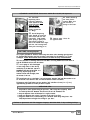
UNPACKING
IMPORT ANT
Prior to starting this procedure, ensure that the shipping carton does not show any evidence of
damage due to dropping or mishandling. This may indicate that the dispenser was damaged during
transit and/or delivery. If any damage is visible on the shipping carton, indicate this on the shipping
receipt.
You can now proceed in the unpacking process by first carefully cutting the plastic strapping which
secures the carton top and bottom. After cutting these straps, lift the carton top straight up and off
of the dispenser.
After lifting the box off the machine, carefully remove the styrofoam from the sides of the machine.
Next remove the four plastic legs, technical and instruction manual, and any other items found in
the mix tanks.
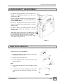
MACHINE POSITIONING
Prior to choosing a location please keep in mind that your dispenser should be readily accessible
for periodic maintenance and have adequate space for necessary air flow. After selecting a
location, you are now ready to place your dispenser.
Place the machine at the desired location. Make sure that there is enough space for ventilation on
both sides (about 8” on each side for 2 and 3 bowl units). Carefully lay the machine on its back and
screw the legs to the bottom. Gently tip machine onto its feet.
To ensure the highest quality in the shipping of your unit, we have left the plastic on both the unit
and the drip trays for protection against scratching in transit. Please remove before operating
your machine.
Install the drip pans and cover grates onto the front of the unit.
IMPORT ANT
Before connecting power to the machine, check the label on the back of the machine to verify the
voltage and amperage draw of the unit and then do the same for the electrical outlet. Carefully
inspect the power supply cord on your dispenser for any possible damage which may have
occurred during transportation. If ANY damage is visible, DO NOT plug the machine into the power
supply, contact your authorized service agent to replace the power cord.
Granita Machine
Page
3
Operation a nd Instruction Manual
FAMILIARIZING YOURSELF WITH THE CONTROLS
On the right side of the machine are the following switches and controls. (Figure 1)
Main Power
“0” Position:
Off position. Power is turned off to all functions.
“I” Position:
On position. Machine has power.
Display light
“0” Position:
Lights are off.
“I” Position:
Lights are on. Display lights have power
Agitator Switch
“0” Position:
Agitator is off.
“I” Position:
Agitator is on.
Cooler Switch
/
“0” Position:
Off position.
“I” Position:
Cool drink mode.
“II” Position:
Frozen mode.
Left bowl
Right bowl
Compressor green light
If the compressor green light is on,
the compressor should be working
Figure 1
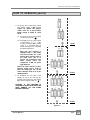
Automatic defrost / standby timer . (Figure 2)
This timer will automatically switch your
dispenser from the frozen drink to the
chilled drink mode. This timer can be
programmed to switch the machine at
any time of the day or night. The
standard settings are:
Switch to chilled from frozen – 11:00 PM
Switch to frozen from chilled – 9:00 AM
For all seven days of the week.
Find detailed programming instructions
on page 13.
Figure 2
Granita Machine
Page
4
Operation a nd Instruction Manual
/6
2 ?
/6
&
%&
2
?
2 6
2
&"
&'
&.& ",
0
,
'
&
'& & &"
( #
5, 6
.
%#
(
"
:,
%
/6
&#
&#
&
2 ?
,
&
. %
. %& "
2,
&
4,
11
&''
)
"
(
% #
##
+# '' % #
'" (
(' & " /' &
:,
(&
!"#
&&"
#'&! - &'
!" &
$
% &'
+
&"
(' !
. % &%
) ''
.
"
)&
& " &'
% & ')
#
"& , #
%
' % " &',
'' % 9 ( #
& . %
,
" ) 8#
( " &" "#
'' )
(' # & (
*
& &##
. %)
& &
6 / 6
2,
!
3
"
' ! '7
"
E
1 E
0& ' ,
2,
&
" ' 2 +4 4 D *5 5 D *: : D
E
# '' )
1
4,
B
/
( )'*
, ! &
" #
% '& /' & % & " &
"
&
6
/ ,
"
3
"
#
&'&
#
!,
#
. (& ; <&(
4=
6& &
"
>,
,
3
5,
' % 6 " / ",
!
& " <
)&
>,
4
5 2 &', # & "
&
)'
#
&
%
"
& " &" " &
%,
% )
& '&
) '' '
'
"
,
6" & "
& &''
"
& "
& ",
A,
''
#
%
B &'! , '&
&
&'' '&
&
#
'& % )
&
,
3
% &
##,
& (
'& " '&
,
#
) ' B &'! &
#
#
'&
,
B
@,
!
& "
,
'
F
6B
66
2
2
C , / & # ''
7 8+ % <
#
,
! (
&
) >
# %
,
"
% '
&
&
7 8+ % &
% ' &; ,
'&
7 8+ % & "
&
&'' '&
&
#
'& % )
&
,
Granita Machine
Page
5
Operation a nd Instruction Manual
/6
2 ?
2
3
" ' 2 +4 4 D *5 5 D *: : D
G &* ( ,
!
) ',
(
# )'
)& "
& #"
* & " '#
'
)' &
'&
"
(& ,
''
) ' ## #
& 2& ; , !
)'
(& ; & " #
'% ' ) ' '' %, '&
;#
'& % )
& ,
G&
G(
H '#
'' ##
I, 2 &
#
&'
& " '' ) & "
1
#"
,
!
& " '&
;#
'& %
)
& ,
J, '' ## 1
% &
((
)
4D &* (, '' ## &
&' 2 & ; , '&
'& % )
# %
',
)
&
&
4D&
2& ;
4D(
##
''2& ;
&', '&
'& %
& ,
;#
)'
;#
,
&
##
&
(9 K, ) ''
2& ;
& % ' &; ,
##
44,
& # '
% )
)& )&
& " & '" "
%
'&
& '
'1 . %
' " & " & & ( ') ,
6 1
4 5 &*(* *",
"
%
45&
Granita Machine
'&
)'
&
# /'
& ,
45( 1
B
)
/ 6
/
,
% )
)&
)& )&
)& ,
&'
45
& "&
&' &
'"
'&"
+
45"
B
)'
&' 2 & ;
Page
6
Operation a nd Instruction Manual
/6
2 ?
2
3
" ' 2 +4 4 D *5 5 D *: : D
4: &*(, /' &
% B &'!
& " (
7 8+
)&
)&
& "
"
% , #
&'' 7 8+ %
,
&
& "
% !
4:&
4:( 7 8+
,
4@,
&''
+&
4A,
! & " '&
( '# %
'% ' & " '' %
, #
' & %*
+ &''
,
&
% )
& '"
' & %*
(& ;
,
%
('
3
) '2& ; )
/F #
/F
,
2& ;
4C, 6 ( &
&
&
((
&',
'
&'' &
#
! " # " % &"
'(
&
" *
#
&',
! ' &
& &,
4G,
&''
((
!
#
4I,
&'
&# &
&''
&'
'&" ! 1 . %
/ ' " , &;
'
" " #
" !
&#
& "
' #
&' '&" ,
& "
'&"
'
& ,
#
& '
'
1 . % / ' " , &;
7/
"8 "
#
&' &%&
#
#&
#
/ '" ,
4J,
' &
&'' &
#
% &"
'( &
" #
&' '&" ,
&"
! ' !
",
#
5D,
&'' ) ',
) '2& ; )
)&
& "
7 ) 8 ( ) ' (& ; & " #
) '
%
!
2 & ; , &;
#
" #
&' '&"
&
&' %
" #
# ) ',
(
" )
& ,
Granita Machine
"& &
&"
"
#
)'
)'
&
"
Page
7
Operation a nd Instruction Manual
/6
2 ?
2
3
" ' 2 +4 4 D *5 5 D *: : D
54, 6 (
55,
&
% B &'!
( & ' % &
&'' &
# # "
% &"
'(
&
'
#&
&
7 8+ %,
&" ' ( &
! ' &
"
7 8+ % ,
5:,
B &'!
&''
%
& "' (
%
"
' ,
& "'
%
'& >
%,
& "'
' &' %
)
%
' ,
&
%
,
(
<)
)
)
, &
)&
5G,
# & .
, 0
&" &
<5> 2 &''
# &
"
) ' #&
&''
&
)&
& "(
%
)&
&
#
5I,
&'' (
6"
" ,
:D
1 ''
&
#
. %
)
# /'
'&
) '6 " ,
% )&
)'
%
#
4
,
5:
&
'
& " & & . % &%
#
& .
&
& " # '' ) &'' &#
'
"
)&
" %
'&( '
,
*"
'
#
'
&
.
6
# &'
& .
(
5A,
'&
&;
. %
5@,
& <A> 2 &''
# 1 " & "' % # 5DD
, /&
3
5C,
'&
%,
) ',
! "
& &
"&
& ' % & "' "
# (
,
' (
,
"
&
%
#
& "
6" ,
% '
)',
(
7 118 & " " &
)
)
1
0 & ' <:> 2 &''
'&
"
#
& "
)
)'
"
&'' &
7
-
.
)
'
7
#
8 & " &'' )
",
8 & " &'' )
)',
#
. <4
&
4 =
,>,
2
4, F
( ) ' & # '' &
(' "
% &''
' ' ! '"
( ')
7
8' & " !
5, F
'& & " & . "
& %
:, &;
& & ' & :8 ' & &
A,
'" (
&
& &'' %
7
/
& ! ) '' &"9
% #
('
E
Granita Machine
/ &''
/&
%&
/
&
, "" #
# '' !
7
'&
" ',
&'' " # &
'" " ;8 "
,
"
&0
"
# ',
8' ,
#' ) ,
% '
,,ID D +C A I +A : I J ,,G "&
%
!
,
'" %
' "&
Page
,
8
Operation a nd Instruction Manual
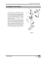
CLEANING THE FAUCET
For machines with a handle locking system,
remove the tap padlock and then take the locking
tap rod away (#8 – arrow I), remove the fastener
(#7 – arrow J), disconnect the dispensing handle
(#1 – arrow K). By pushing upward (arrow L), take
the spring (#3) out from its holder (#2 – arrow M),
then push the piston downward (#6 – arrow N),
remove the o-ring (#5 – arrow P) and the special
gasket (#4 – arrow Q).
Proceed to clean everything with water and neutral
soap, rinse and reassemble without damaging the
gaskets as follows: put in place the special gasket
(#4 – arrow A), put the o-ring (#5) back in its piston
slot (#6 – arrow C), insert the spring (#3 – arrow
D), put the cap in place (#2 – arrow E), put the
handle in place (#1 – arrow F), insert the fastener
(#7 – arrow G), and if you want to lock the tap,
insert the locking tap rod (#8 – arrow H) and lock.
Figure 8
Granita Machine
Page
9
Operation a nd Instruction Manual
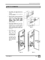
HOW TO OPERATE
1. The machines come from factory with a
handle locking system (fig 9) (locker (3) not
included).
To unlock, remove the locker and pull out
the rod (1) (arrow A).
2. Once the bowl has been cleaned and
sanitized, fill the mix tank with the desired
liquid product (3 gallons maximum). Do not
overfill the tank. NOTE THAT WHEN
READY, SLUSH OCCUPIES MORE
VOLUME
THAN
THE
LIQUID
(approximately 3.5 gallons of slush for 3
gallons of liquid).
3. If using natural products as a base (coffee,
lemon juice, orange juice, etc.), it is
required that 5 to 7 oz. of sugar per gallon
be added. If using a concentrate, follow the
mixing instructions from the supplier. In
general the brix ratio (sugar content) of the
product solution (liquid mix) should not be
less than 11.
Figure 9
4. To
access
to
switches and timer,
open
the
switch
panel
cover
by
pushing on the side
(arrow A)and pulling
(arrow A’) (Fig. 10).
To close the cover
(arrow B’), push on
the front (arrow B)
until the clear plastic
part (1) snaps closed
(Fig. 11).
Figure 10
Granita Machine
Figure 11
Page
10
Operation a nd Instruction Manual
HOW TO OPERATE (cont’d)
4. To operate, press main power switch
and agitator switch to ON position
(Figure 12). NOTE: The agitator
switch must be to ON position
before setting to liquid or slush
mode.
4.1 For slush, press the cooler switch
to bottom position ( II /
).
4.2 For liquid, press the cooler switch
to up position ( I /
) . If the
machine is being used as a liquid
cooler, it is provided with an
inside thermostat for controlling
the liquid temperature.
Note that your machine is
equipped with a time delay
relay that provides for a four
minute delay from the time of
the initial start. This is to
prevent the compressor from
short
cycling.
Once
the
compressor is ON, the green
light will be on.
1 bowl
LEFT
RIGHT
Note: The cooler switch is a three
position switch and in order to
have the compressor off, all the
cooler switches need to be in the
middle position.
2 bowls
5. To illuminate the mix tank cover
display on top of the unit and the
product in the bowl press the display
light switch to down position ( I /
).
LEFT
CAUTION: IF THE MACHINE IS
STOPPED AT NIGHT WITH ICE IN THE
TANK, REMOVE ALL ICE SLABS
BEFORE STARTING.
MIDDLE
RIGHT
3 bowls
Figure 12
Granita Machine
Page
11
Operation a nd Instruction Manual
LIQUID DENSITY ADJUSTEMENT
To adjust the density/consistency of the slush there is an
adjustment knob (Figure 13, #2) at the rear, right corner
of the dispenser (#1).
Turn the knob right (clockwise) or left (counter clockwise)
(arrow C and B) The consistency indicator (#4) will go up
or down (arrow D and E)
To firm up the product, turn the set knob counter
clockwise, which will move the indicator down to a higher
number position
To soften / warm up the product, turn the set knob
clockwise, which will move the indicator up to a lower
number position
NOTE: when using a new product, or on initial start up, it
is recommended that you set the consistency indicator to
the lowest/warmest setting and increase as desired.
Please note that the machines are pre-set at the factory
at a medium setting (number 2.5)
Figure 13
TANK WITH PADLOCK
Fitting the lid over the tank (Figure 14):
1º Slide the rim into the slot situated at the back of the tank.
Lift slightly the front of the lid.
2º Lower the lid and fit onto the tank.
3º Insert the padlock into holes of the front rims of the tank
and the lid. Close it.
Note:
A. The lid can be turned back to front (reversible). Proceed
as above.
B. In order to take off the lid, the padlock must be opened
and released; then follow the instructions in reverse
order
Figure 14
Granita Machine
Page
12
Operation a nd Instruction Manual
DEFROST TIMER PROGRAMMING PROCEDURES
COARSE
ADJUSTEMENT
Turn switching dial
direction of the arrow
courrent time is
opposite the marking
(here 19.45).
FINE
ADJUSTEMENT
Continue turning the minute
hand in the direction of the
arrow until the courrent time is
opposite the marking arrow F
(here : Th 20.00).
Granita Machine
in the
until the
almost
arrow F
Page
13
Operation a nd Instruction Manual
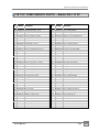
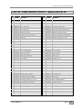
LIST OF COMPONENTS PARTS – Model GB-110 FF
#
#
1 SL300951200 Evaporator Assembly
2 SL310000009 Left Side Panel 2002 - 1 bowl
3 SL300970010 Upper tray GB-110 white
4 SL300310051 Stainless steel screw NFE 27128 M4x10
5 SL310000002 Front panel GHZ-114 V/2002
6 SL38WZC0005 Rapid fuse F 5A 250V U.L.
7 SL300951610 Condenser SENCO151 GHZ-114 RP 01
8 SL300901135 Fuse Holder U.L. 5x20
9 SL300950840 Full adjustable foot V/US
10 SL300950746 Zinc screw DIN-933 M6x50
11 SL300970081 Thermostat support bracket
12 SL37TBH1411 Fan motor 120x120x38 115/60 U.L.
13 SL300950584 Timer GHZ-114 115/60
14 SL300950230 Drain Tube
15 SL300950570 Transformer 20VA 120/12v
16 SL310000305 Side Switch Panel GHZ-114 TP 02 CLDT
17 SL300951088 Switch 20A black U.L.
18 SL300950210 Zinc screw D-933 M4x45
19 SL300951089 Mode selector switch – 3 position
20 SL300950835 Screen for leaking GHZ V/97 white
21 SL300951246 Tray for leaking GHZ blue
22 SL300970331 Cover cable GB-10 COLD. with jack
23 SL300310157 Zinc screw DIN 84 M4x20
24 SL300310052 Stainless steel screw NFE 27128 M6x10
25 SL300950583 Zinc screw D-7981 B3'5x9'5
26 SL300310353 Zinc washer DIN 125 M6
27 SL300310320 Zinc screw D-7971 B2'2x7
28 SL300350467 Thermostat GB RANKO K50 P1115
29 SL300310271 Zinc nut D-934 M6
30 SL300310354 Zinc washer DIN 9021 M6
31 SL300951763 Zinc screw D-933 M6x60
32 SL300970276 Command side panel cover - Black
33 SL300970294 Bolt cover black
34 SL300951469 Compressor NE2125GK 115/60
35 SL310000245 Full chassis GHZ-114 V/2002
36 SL300951357 Rubber foot GHZ-14 V/99
37 SL300310134 Zinc screw D-933 M8x20
38 SL300950759 Zinc screw D-933 M6x12
39 SL300951253 Green pilot light 110v U.L.
40 SL300950069 Upper tray tap
41 SL300950735 Terminal Block Cord Connection PA44 U.L.
42 SL300950737 Terminal block mounting bracket PA52
43 SL300310141 Zinc screw D-84 M3x25
44 SL300951247 Evaporator support cover GHZ blue GBG
45 SL300951868 Evaporator support GHZ PZ.1 white
46 SL300310042 Stainless steel screw D-963 M4x12
47 SL300950587 Full micro switch GHZ V/99
48 SL300950810 Zinc screw RA-71 2'5x25
49 SL300951869 Evaporator support GHZ PZ.2 white
50 SL300950760 Zinc screw D-7971 B2'9x13
51 SL3GS12035B Adjustment screw GHZ-14 white
52 SL3GS12036A Consistency adjust. screw guide holder
53 SL3GS12037B Consistency screw guide GHZ
54 SL300950116 Regulation spring GHZ 1/4 hard
55 SL300950445 Zinc screw D-7971 B2'9x9'5
56 SL300310203 Stainless steel nut D-934 M4
57 SL300500118 Pass cable PA107 U.L.
58 SL300901578 Zinc washer DIN 125 M4
59 SL300310250 Brass nut DIN 934 M6
60 SL300950649 Brass washer DIN 125 M6
61 SL300950648 Brass screw D-933 M6x25
62 SL310000111 Back panel GHZ-114 U.L. 2002
63 SL310000010 Right side panel GHZ-114 V/2002
64 SL300950833 Nut supplement foot
65 SL300950624 Adjustable supplement foot V/US
66 SL300951368 Supplement foot tap V/US
67 SL300950427 Zinc screw DIN 84 M4x25
68 SL300951468 Compressor Relay NE2125KG 115/60
69 SL300951467 Compressor Klixon NE2125GK 115/60
70 SL38GZDG060 Transformer Washer
71 SL300950798 Transformer Cover
72 SL300970277 Daily hourly timer 115/60
73 SL300951365 Relay 115/60
74 SL300951921 Zinc screw DIN 7981 B3’9x13
75 SL300951694 Pass cable evap. support cover COLD.
76 SL310000171 Special nut M4 03-09
77 SL300970114 Tap screw GB-10 grey
78 SL300951412 Locking
79 SL310000400 Locking special screw
80 SL310000119 Thermal disk protection
81 SL310000354 Thermal disk clamp SP USA
Granita Machine
Page
14
Operation a nd Instruction Manual
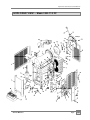
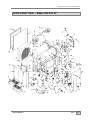
EXPLODED VIEW – Model GB-110 FF
Granita Machine
Page
15
Operation a nd Instruction Manual
LIST OF COMPONENTS PARTS – Model GB-220 FF
#
1
2
3
4
5
6
7
8
9
10
11
12
13
14
15
16
17
18
19
20
21
22
23
24
25
26
27
28
29
30
31
32
33
34
35
36
37
38
39
40
41
42
43
44
45
46
47
48
49
50
51
52
#
SL300951200
SL300970240
SL300970008
SL300310051
SL300951596
SL38WZC0005
SL300970233
SL300901135
SL300951632
SL300951631
SL300000233
SL37TKU1N16
SL300951202
SL300950230
SL300950571
SL300970297
SL300951088
SL300951253
SL300951089
SL300950835
SL300951246
SL300970331
SL300950427
SL300310052
SL300950583
SL300350467
SL300970114
SL300951748
SL300310271
SL300310354
SL300310160
SL300310322
SL300950075
SL37ZG12168
SL310000411
SL300951357
SL300310134
SL300950265
SL300950660
SL300950069
SL300950735
SL300950737
SL300950568
SL300951247
SL300951868
SL300310042
SL300950587
SL300950810
SL300951869
SL300950760
SL3GS12035B
SL3GS12036A
Evaporator Assembly
Left side panel GB-20/30 U.L.01
Upper tray GB-220 white
Stainless steel screw NFE 27128 M4x10
Front panel GHZ-228 V/2001
Rapid fuse F 5A 250V U.L.
Condenser SEN122 GHZ 2/3 RP BAF1
Fuse holder U.L. 5x20
Drain tube connection racor GHZ white
Drain tube connection GHZ white
Fan blade 16W 254mm/28º
Motoventilator 16W 115V/60 U.L.
Electronic regulator 115V V/97
Drain Tube
Transformer 50VA 115V/ 12V
Side switch panel GB-220 PRG/01
Main switch 20 Amp.
Green pilot light U.L.
Mode selector switch – 3 position
Screen for leaking GHZ V/97 white
Tray for leaking GHZ blue GBG
Cable with jack cover GB-10
Zinc screw D-84 M4x25
Stainless steel NFE 27128 M6x10
Zinc screw D-7981 B3'5x9'5
Thermostat GB RANKO K50 P1115
Tap screw GB-10 grey
Thermostat support GHZ-228 RP U.L.
Zinc nut DIN 934 M6
Zinc washer DIN 9021 M6
Zinc screw D-933 M6x16
Zinc screw D-7971 B3’5x21’5
Supplement timer board
Compressor T2168GK CSIR 115/60
Full chassis GHZ-228 STN/UL 02
Rubber foot GHZ-14 V/99
Zinc screw D-933 M8x20
Zinc screw D-84 M5x6
Compressor condenser T2168GK CSIR 115v
Condensate tray screw plug
Terminal block cord connection PA-44
Terminal block mounting bracket
Special nut CWP M4
Evaporator support cover blue GBG
Evaporator support GHZ PZ-1 white
Stainless steel screw D-963 M4x12
Consistency control switch
Zinc screw RA-71 2'5x25
Evaporator support GHZ PZ-2 white
Zinc screw D-7971 B2'9x13
Consistency adjustment screw V/99 white
Consistency adjustment screw guide holder
Granita Machine
53 SL3GS12037B Screw Guide & indicator- Consistency adj.
54 SL300950116 Consistency adjustment spring
55 SL300950833 Nut supplement foot
56 SL300310203 Hex nut -stainless steel 4mm
57 SL300950445 Screw – 2.9x9.5
58 SL300970155 Clamp-solenoid valve coil V/99
59 SL300951421 Electrovalve bobbin 115/60
60 SL300970159 Double solenoid valve body 115/60
61 SL3GS24711D Double solenoid valve assembly 115/60
62 SL300970239 Rear panel 2001 -2 bowl
63 SL300970242 Right side panel 2001 -2/3 bowl
64 SL300310141 Screw - 3x25mm
65 SL300951101 Double solenoid valve mounting bracket
66 SL300950428 Spacer-rear panel 2/3 bowl
67 SL300950624 Adjustable supplement foot V/US
68 SL300951472 Compressor relay T2168GK CSIR 115/60
69 SL300951473 Compressor klixon T2168GK CSIR 115/60
70 SL300500118 Pass cable PA-107
71 SL300310101 Hex bolt 8x35mm
72 SL300310255 Washer 10mm
73 SL300310205 Hex nut 8mm
74 SL300950746 Hex bolt 6x50 mm
75 SL300950427 Zinc screw DIN 84 M4x25
76 SL300310320 Screw - 2.2x7mm.
77 SL300310353 Washer - 6mm
78 SL300950798 Transformer cover
79 SL300950759 Screw 6x12mm
80 SL300970276 Command side panel cover - Black
81 SL38GZDG060 Transformer washer
82 SL300970294 Bolt cover - black
83 SL300310250 Brass nut 6mm
84 SL300950649 Brass washer 6mm
85 SL300950648 Bras screw 6x25mm
86 SL300950210 Screw 4x45mm
87 SL300901578 Washer - 4mm
88 SL300951368 Supplement foot tap V/US
89 SL300950840 Full adjustable foot V/US
90 SL300951575 Compressor condenser box
91 SL300310179 Screw - 5x15mm
92 SL300970277 Daily hourly timer
93 SL300951365 Relay 115V/60Hz
94 SL300900005 Hex nut 3 mm
95 SL300951694 Pass cable 31583
96 SL300951412 Locking
97 SL310000400 Locking special screw
98 SL310000119 Thermal disk protection
99 SL310000354 Thermal disk clamp SP USA
100 SL310000121 External condenser filter SP USA 01
101 SL300310148 Zinc screw DIN 933 M6x10
102 SL300906167 Zinc nut DIN 934 M5
103 SL300310355 Zinc washer DIN 125 M5
104 SL300951921 Zinc screw DIN 7981 B-3’9x13
Page
16
Operation a nd Instruction Manual
EXPLODED VIEW – Model GB-220 FF
Granita Machine
Page
17
Operation a nd Instruction Manual
LIST OF COMPONENTS PARTS – Model GB-330 FF
#
1
2
3
4
5
6
7
8
9
10
11
12
13
14
15
16
17
18
19
20
21
22
23
24
25
26
27
28
29
30
31
32
33
34
35
36
37
38
39
40
41
42
43
44
45
46
47
48
49
50
51
52
53
#
SL300950585
SL300970240
SL300970009
SL300310051
SL300951597
SL38WZC0005
SL300970233
SL300901135
SL300951632
SL300951631
SL300000233
SL37TKU1N16
SL300951202
SL300950230
SL300950572
SL300970298
SL300951088
SL300951253
SL300951089
SL300950835
SL300951246
SL300970331
SL300310157
SL300310052
SL300950583
SL300310179
SL300350467
SL300950448
SL300310271
SL300310354
SL300310160
SL300310157
SL300950075
SL300951256
SL310000426
SL300951357
SL300310134
SL300950210
SL300951257
SL300950069
SL300950735
SL300950737
SL300950568
SL300951247
SL300951868
SL300310042
SL300950587
SL300950810
SL300951869
SL300950760
SL3GS12035B
SL3GS12036A
SL3GS12037B
Evaporator Assembly
Left side panel 2001 2/3 bowl
Condensate drip tray 3 bowl
Screw-Stainless steel 4x10mm
Front panel 2001 3 bowl
Fuse – transformer
Air condenser SENC122 GHZ 2/3 RP BAF1
Fuse holder 5x20
Drain tube connection racor
Drain tube connection
Fan blade - 10” x 28 degrees
Condenser fan motor – 2/3 bowl
Electronic timer – 2/3 bowl
Drain Tube
Transformer 60 W/ 115V/ 12V – 2 bowl
Side switch panel 2001 – 3 bowl
Main switch 20 Amp.
Green pilot light U.L.
Mode selector switch – 3 position
Front Drip Tray Cover – White
Front Drip Tray - Blue
Cable with jack cover GB-10
Zinc screw D-84 M4x20
Screw -Stainless steel 6x10mm
Screw 3,5 x 9,5 mm
Screw – 5x15mm
Thermostat-stand by mode
Thermostat support
Hex nut 6mm
Washer 6mm
Screw 6x15mm
Screw 4x20 mm
Stand off – timer board
Compressor T2178GK 115/60
Full chassis GHZ-342 STN/UL 02
Rubber foot H-40mm
Hex bolt 8x20mm
Screw – 4x45mm
Compressor condenser T2178GK 115/60
Condensate tray screw plug
Terminal block cord connection PA-44
Terminal block mounting bracket
Nut – side panel mount
Rear plastic gearmotor cover - Blue
Evaporator support GHZ PZ-1 white
Screw-Stainless Steel 4x12mm
Consistency control switch
Screw 2.5x25 mm
Evaporator support GHZ PZ-2 white
Screw 2,9x13mm
Consistency adjustment screw V/99
Consistency adjustment screw guide holder
Screw Guide & indicator- Consistency adj.
Granita Machine
54 SL300950116 Consistency adjustment spring
55 SL300950833 Nut supplement foot
56 SL300310203 Hex nut -stainless steel 4mm
57 SL300950265 Screw – 5x6mm
58 SL300970155 Clamp-solenoid valve coil V/99
59 SL300951421 Electrovalve bobbin 115/60
60 SL300970157 Triple solenoid valve body 115/60
61 SL3GS36711D Triple solenoid valve assembly 115/60
62 SL300970246 Rear panel 2001 -3 bowl
63 SL300970242 Right side panel 2001 -2/3 bowl
64 SL300310141 Screw - 3x25mm
65 SL300951101 Double solenoid valve mounting bracket
66 SL300950428 Spacer-rear panel 2/3 bowl
67 SL300950624 Adjustable supplement foot V/US
68 SL300951258 Compressor relay T2178GK 115/60
69 SL300951259 Condenser running T2178GK 115/60
70 SL300500118 Pass cable PA-107
71 SL300310101 Hex bolt 8x35mm
72 SL300310255 Washer 10mm
73 SL300310205 Hex nut 8mm
74 SL300950746 Hex bolt 6x50 mm
75 SL300950427 Zinc screw DIN 84 M4x25
76 SL300950759 Screw – 6x12mm
77 SL300310353 Washer - 6mm
78 SL300310320 Screw – B-2’2x7
79 SL300951368 Antiskid supplement foot tap
80 SL300901578 Washer - 4mm
81 SL38GZDG060 Transformer washer
82 SL300950798 Transformer cover
83 SL300310250 Brass nut 6mm
84 SL300950649 Brass washer 6mm
85 SL300950648 Bras screw 6x25mm
86 SL37TBH1411 Motoventilator 120x120
87 SL300950445 Screw – 2.9x9.5
88 SL300950840 Full adjustable foot V/US
89 SL300970294 Bolt cover - black
90 SL300970276 Command side panel cover - Black
91 SL300951575 Compressor condenser box
92 SL300950035 Condenser SENC0014 GHZ-114/456
93 SL300970114 Screw GB-10 grey
94 SL300970277 Daily hourly timer
95 SL300951365 Relay 115/60
96 SL300900005 Hex nut 3 mm
97 SL300310148 Zinc screw DIN 933 M6x10
98 SL300951412 Loking
99 SL310000400 Locking special screw
100 SL310000119 Thermal disk protection
101 SL310000354 Thermal disk clamp SP USA
102 SL310000121 External condenser filter SP USA
103 SL300951694 Pass cable 31583
104 SL300951921 Zinc screw DIN 7981 B-3'9x13
105 SL300906167 Zinc nut DIN 934 M5
106 SL300310355 Zinc washer DIN 125 M5
Page
18
Operation a nd Instruction Manual
EXPLODED VIEW – Model GB-330 FF
Granita Machine
Page
19
Operation a nd Instruction Manual
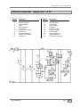
WIRING DIAGRAM – Model GB-110 FF
Number
1
2
3
4
5
6
7
8
9
10
11
Description
General switch and shovels
Engine for shovels
Motor ventilator 1
Timer
Micro regulation
Timer micro
Liquid/iced drink switch
Switch relais
Mechanical thermostat
Compressor pilot light
Compressor
Granita Machine
Number
12
13
14
15
16
17
18
19
20
21
22
Description
Hourly timer
Bowl light switch
Transformer
Full fuse holder
Bowl light
Compressor klixon
Compressor relay
Connector light
Socket display lamp
Motor ventilator 2
Thermal disk protection
Page
20
Operation a nd Instruction Manual
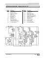
WIRING DIAGRAM – Model GB-220 FF
Number
1
2
3
4
5
6
7
8
9
10
11
12
13
14
Description
General switch
Electronic regulator
Compressor pilot light
Compressor
Motor ventilator
Bowls light switch
Transformer
Full fuse holder
Bowls light
Left shovels switch
Engine for left shovels
Left liquid/iced drink switch
Left mechanical thermostat
Left micro regulation
Granita Machine
Number
15
16
17
18
19
20
21
22
23
24
25
26
27
28
Description
Left electrovalve
Switch relais
Right shovels switch
Engine for right shovels
Right liquid/iced drink switch
Right mechanical thermostat
Right micro regulation
Right electrovalve
Hourly timer
Compressor klixon
Compressor relay
Connector lights
Socket display lamp
Thermal disk protection
Page
21
Operation a nd Instruction Manual
WIRING DIAGRAM – Model GB-330 FF
Number
1
2
3
4
5
6
7
8
9
10
11
12
13
14
15
16
17
18
Description
General switch
Electronic regulator
Compressor pilot light
Compressor
Motor ventilator 1
Bowls light switch
Transformer
Full fuse holder
Bowls light
Left shovels switch
Engine for left shovels
Left liquid/iced drink switch
Left mechanical thermostat
Left micro regulation
Left electrovalve
Switch relay
Central shovels switch
Engine for central shovels
Granita Machine
Number
19
20
21
22
23
24
25
26
27
28
29
30
31
32
33
34
35
Description
Central liquid/iced drink switch
Central mechanical thermostat
Central micro regulation
Central electrovalve
Right shovels switch
Engine for right shovels
Right liquid/iced drink switch
Right mechanical thermostat
Right micro regulation
Right electrovalve
Hourly timer
Compressor klixon
Compressor relay
Connector lights
Socket display lamp
Motor ventilator 2
Thermal disk protection
Page
22
Operation a nd Instruction Manual
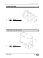
WATERTIGHTNESS AND TRANSMISSION ELEMENTS
#
Coldelite
1
2
3
4
5
6
7
SL300951752
SL300951857
SL3GS36007B
SL3GS12030A
SL300950254
SL300950321
SL3MS4M015C
Description
Evaporator cap GHZ-14 2001
Watertight shaft joint GHZ-14 2002
Tank joint
Beater Drive Shaft
Shocket DIN 471 E-12
Transmission shaft racor GHZ-14 V/95
Gear motor 220/50 - 115/60 U.L.
Only parts with numbers will be stock items; others will be special ordered.
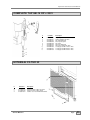
COVER GB
#
Coldelite
1
2
3
4
5
6
7
8
9
10
11
12
13
14
15
SL300970269
SL300951284
SL3GS24317A
SL300950100
SL300950679
SL300310157
SL300970252
SL300310633
SL300950646
SL300951583
SL300950075
SL300950350
SL300950583
SL300970355
SL300970256
Granita Machine
Description
Reversible mix tank Cover - Top (blue)
Diapositive
Lamp holder B-15-S
Lamp 21W. 12V.
Wire-Display Lamp Ground
Zinc screw D-84 M4x20
Full cable cover
Terminal connection block
Terminal Block - display light
Mix tank Cover Base v/padlock
Supplement
Display Lamp Shocket Bracket
Zinc screw D-7981 B3’5x9’5
Transparency cover sujection blue
Mix Tank Cover Assembly v/padlock - Blue
Page
23
Operation a nd Instruction Manual
SPIRAL SHOVEL
#
Coldelite
1
SL3GS12009D
Description
Mixer Blade Assembly GHZ-14
TANK AND SHOVEL GUIDE
#
Coldelite
1
2
SL300951582
SL300951369
Granita Machine
Description
Mix Storage Tank v/padlock
Padlock
Page
24
Operation a nd Instruction Manual
COMPLETE TAP GB-14 RP v.2001
#
Coldelite
1
2
3
4
5
6
7
81
82
83
SL300951606
SL300951601
SL300951647
SL300950258
SL300950194
SL300951604
SL300951605
SL300951660
SL300951607
SL300951608
Description
Dispensing handle GHZ USA -white
Spring cap GHZ USA -white
Tap spring GHZ USA
Piston special gasket
Tap gasket
Tap piston GHZ USA
Tap fastener GHZ USA -white
Locking tap rod GB-110 2001 -white
Locking tap rod GB-220 2001 -white
Locking tap rod GB-330 2001 -white
EXTERNAL FILTER 02
#
Reference
2
3
4
SL310000121
SL310000180
SL300310051
Granita Machine
Description
External condenser filter SP USA 01
External condenser filter support
Stainless steel screw NFE 27128 M4x10
Page
25
Operation a nd Instruction Manual
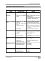
TROUBLE SHOOTING GUIDE
Trouble
Possible Causes
Remedy
Machine overheats
• Machine vents are blocked
• Check that nothing is obstructing the
vents
The tap drips
• O-rings may be improperly
placed
• Make sure that the o-rings are in place
and have no cuts.
• Check that the piston is correctly closed
and nothing is obstruction its outlet.
• Verify that the spring works correctly.
Machine is not cooling the
product*
• Voltage may
improperly
• Does the
power?
The unit does not work
One of the augers does not
work
No pilot light when unit is on
Compressor does not start
Granita Machine
be
labelled
• Verify that the voltage supply matches
the label on the back of the machine.
have
• Check to see if the machine is plugged
in.
machine
• The condenser is dirty
• Clean the condenser carefully with a
brush trying not to damage the ribs.
See figure 7.
• No refrigerant
• Contact authorized service agency.
• No power
• Connect unit to power supply.
• Switch Power cord loose or
damaged
• Locate problem and correct. Replace
power cord if necessary.
• Defective
• Replace switch.
• Wiring disconnected
• Check wiring for loose connection or
broken wire.
• Motor connection loose
• Check wiring to motor.
• Defective switch
• Replace switch.
• Auger is stuck
• Check auger, replace if necessary.
• Bad gear reducer motor
• Replace.
• Defective wiring connection
• Check wiring.
• Defective density switch
• Check switch.
• Burned out bulb
• Replace bulb.
• Defective thermostat
• Replace thermostat.
• Defective overload
• Replace.
• Defective relay
• Replace.
• Defective compressor
• Replace.
Page
26
Operation a nd Instruction Manual
TROUBLE SHOOTING GUIDE (cont’d)
Trouble
Unit cools but does not
freeze
Possible Causes
Remedy
• Switch is not on
• Check that switch is on right position.
• The condenser is dirty
• Clean the condenser carefully with a
brush (do not to damage the ribs).
• Not enough air around the unit
• Remove other objects that may be
blocking airflow around unit.
• Less than 12% sugar content
• Remix with 12% sugar content.
• Density switch at lower level
off
• Turn on density switch.
• Defective solenoid valve
• Replace.
• Defective thermostat
• Replace.
• Defective density switch
• Replace.
• Defective front panel switch
• Replace.
• Density switch at lower level
defective
• Replace.
• Front panel switch set for
liquid
• Check that switch is in right position.
• No lubricant
• Lubricant auger.
• Defective gear reducer motor
• Replace.
Drippy nozzle or valve
• O-Rings worn or defective
• Replace O-Rings.
Leaky Bowl
• Gasket improperly installed or
defective
• Reinstall gasket, replace if necessary.
Cover light does not work
• Burned out bulb
• Replace bulb.
• Defective cable
• Replace cable.
• Defective plug
• Replace plug.
• Defective fuse
• Replace fuse.
• Defective transformer
• Replace transformer.
• Defective light switch
• Replace switch
One bowl does not cool*
One bowl cools but does not
freeze*
Noisy auger
Granita Machine
Page
27
Granita Machine
Page
28
1 Bowl
2 Bowl
Company Telephone #
336-661-9895 (Fax)
Email Address
*Warranty card must be returnedwithin 30 days of purchase to activate warranty
Manufacturer extends no warranty on equipment without returned warranty card
Your Company Name
Contact Person
Your Company Address
3 Bowl
336-661-9893
Granita Equipment
Warranty Form
4069 Winston Salem, NC 27115
Serial # (six digits on switch plate side)
*Date Purchased
Date Installed
Retailer/Wholesaler purchased from
Retailer/Wholesaler Address
P.O. Box
P.O. Box
4069 Winston Salem, NC 27115
336-661-9893
P.O. Box 4069
Winston-Salem, NC 27115
336-661-9895 (Fax)