1
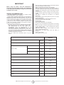
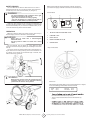
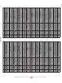
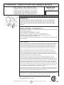
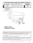
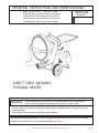
OPERATING INSTRUCTIONS AND OWNER’S MANUAL
READ INSTRUCTIONS CARE FULLY: Read
HEATSTAR
and follow all instructions. Place instructions in
BY ENERCO
MODEL
a safe place for future reference. Do not allow
anyone who has not read these instructions to
assemble, light, adjust or operate the heater.
HS155IR
DIRECT FIRED INFRARED
PORTABLE HEATER
the information in this manual is not followed exactly, a fire or explosion
WARNING : Ifmay
result causing property damage, personal injury or loss of life.
— Do not store or use gasoline or other flammable vapors and liquids in the vicinity of this or any
other appliance.
— Service must be performed by a qualified service agency.
This is an unvented portable heater. It uses air (oxygen) from the area in which it is used. Adequate
combustion and ventilation air must be provided. Refer to page 5.
ENERCO GROUP, INC., 4560 W. 160TH ST., CLEVELAND, OHIO 44135 • 800-251-0001
07/11 50014
WARNING:
WARNING:
YOUR SAFETY IS IMPORTANT TO YOU AND TO OTHERS,
SO PLEASE READ THESE INSTRUCTIONS BEFORE YOU
OPERATE THIS HEATER.
NOT FOR HOME OR RECREATIONAL VEHICLE USE
WARNING:
GENERAL HAZARD WARNING:
FIRE, BURN, INHALATION, AND EXPLOSION HAZARD.
KEEP SOLID COMBUSTIBLES, SUCH AS BUILDING MATERIALS, PAPER OR CARDBOARD, A SAFE DISTANCE
AWAY FROM THE HEATER AS RECOMMENDED BY THE
INSTRUCTIONS NEVER USE THE HEATER IN SPACES
WHICH DO OR MAY CONTAIN VOLATILE OR AIRBORNE
COMBUSTIBLES, OR PRODUCTS SUCH AS GASOLINE,
SOLVENTS, PAINT THINNER, DUST PARTICLES OR UNKNOWN CHEMICALS.
FAILURE TO COMPLY WITH THE PRECAUTIONS AND
INSTRUCTIONS PROVIDED WITH THIS HEATER, CAN
RESULT IN DEATH, SERIOUS BODILY INJURY AND
PROPERTY LOSS OR DAMAGE FROM HAZARDS OF FIRE,
EXPLOSION, BURN, ASPHYXIATION, CARBON MONOXIDE POISONING, AND/OR ELECTRICAL SHOCK.
ONLY PERSONS WHO CAN UNDERSTAND AND FOLLOW
THE INSTRUCTIONS SHOULD USE OR SERVICE THIS
HEATER.
IF YOU NEED ASSISTANCE OR HEATER INFORMATION
SUCH AS AN INSTRUCTIONS MANUAL, LABELS, ETC.
CONTACT THE MANUFACTURER.
WARNING:
The State of California requires the following warning:
COMBUSTION BY-PRODUCTS PRODUCED WHEN USING THIS PRODUCT CONTAIN CARBON MONOXIDE,
A CHEMICAL KNOWN TO THE STATE OF CALIFORNIA
TO CAUSE CANCER AND BIRTH DEFECTS (OR OTHER
REPRODUCTIVE HARM).
Contents
WARNING:
WARNINGS................................................................................... 2
READ THE INSTRUCTIONS GIVEN IN THIS
MANUAL BEFORE USING THE APPLIANCE.
SPECIFICATIONS............................................................................ 3
• DO NOT USE GASOLINE, NAPHTHA OR VOLATILE
FUELS.
Safety devices........................................................................... 4
operation.................................................................................. 4
MAINTENANCE............................................................................. 5
• THE ELECTRICAL SYSTEM TO WHICH THE APPLIANCE
IS CONNECTED MUST COMPLY WITH ALL SAFETY
REGULATIONS IN FORCE. A RESIDUAL CURRENT
CIRCUIT BREAKER MUST BE PROVIDED ON THE MAIN
DISTRIBUTION BOARD.
TROUBLESHOOTING..................................................................... 6
wiring diagrams...................................................................... 7
parts list.................................................................................... 8
• UNPLUG THE HEATER BEFORE ATTEMPTING ANY
SERVICE OR MAINTENANCE.
• ALWAYS CHECK THE POWER SUPPLY CABLE BEFORE
USE. IT MUST NOT BE BENT, CRUSHED, OR ANYWAY
DAMAGED.
• THE POWER SUPPLY CABLE MUST BE REPLACED ONLY
BY QUALIFIED PERSONNEL.
• ONLY USE AN ORIGINAL H07RN-F POWER CABLE
WITH WATERPROOF PLUG.
• DO NOT TOUCH THE EXHAUST GAS OUTLET. DANGER
OF BURNS!
ENERCO GROUP, INC. |Direct Fired Portable Heater
2
Operating Instructions and Owner’s Manual
IMPORTANT
• Never use heater in immediate proximity of flammable materials
(the minimum distance must be 10 feet);
• Make sure fire fighting equipment is readily available;
• Make sure sufficient fresh outside air is provided according to
the heater requirements. Direct combustion heaters should only
be used in well vented areas in order to avoid carbon monoxide
poisoning;
• A rough estimate of opening required for each gallon (US) of
capacity is three square foot at heater level, for direct-fired
heaters;
• The heater is installed and connected to an electrical
switchboard;
• Ensure that the machine resting surface or ground is not made
of flammable material;
• Minimum clearances from combustible material must be:
30” from side and rear (air inlet) of heater
80” from ceiling
40” on air outlet of heater.
• Never block air inlet (rear) or air outlet (front);
• In case of very low temperatures add kerosene to the heating
oil;
• Connect the power cord to the mains and wait 15 min at least
be fore starting heater, to allow pre-heated filter warming
heating oil inside the filter;
• Make sure heater is always under surveillance and keep
children and animals away from it;
• Before starting the heater always check free rotation of
ventilator;
• Heater is not ductable.
• Unplug heater when not in use.
Before using the heater, read and understand all
instructions and follow them carefully. The manufacturer
is not responsible for damages to goods or persons due
to improper use of units.
GENERAL RECOMMENDATIONS
The heater described in this manual is a portable oil-fueled
infrared heat generator running on heating oil.
Its easy handling and large fuel tank allow it to be used locally and
temporarily with complete stand-alone operation. The area to be
heated is therefore hit by an even and uniform flow of heat, as can be
seen by the shape of the irradiation cone (18), without air movement.
The unit is a direct combustion hot generator that works by
sending both hot air and combustion products in the room you wish
to heat: all the necessary precautions must therefore be taken to
guarantee a sufficient exchange of air.
Always follow local ordinances and codes when using this heater:
• Read and follow this owner’s manual before using the heater;
• THE INSTALLATION OF THE UNIT SHALL BE IN
ACCORDANCE WITH THE REGULATIONS OF THE
AUTHORITIES HAVING JURISDICTION. Also, as a
recommended installation practice reference should be made to
the current issue of CSA B139, Installation Code for Oil Burning
Equipment in Canada and NFPA 31 Standard for the Installation
of Oil-Burning Equipment In the USA;
• Use only in places free of flammable vapours or high dust
content;
TECHNICAL SPECIFICATIONS
FIRE 155
Max heating output
Fuel consumption
[BTU/h]
154.237
[gal/h]
1,11
Phase
Power supply
1
Voltage
Frequency
Power consumption
Nozzle
Pump pressure
120
[Hz]
60
[W]
440
[USgal/h]
Delavan 0,85 - 80° W
PSI
Adjustment of combustion air flap
Tank capacity
Noise level at 1 m
Dimensions, L x W x H
Weight
ENERCO GROUP, INC. |Direct Fired Portable Heater
[V]
3
174
[N°]
2
[USgal]
17.17
[dBA]
72
[in]
55.5 x 28.03 x 41.5
[lb]
161
Operating Instructions and Owner’s Manual
Before any attempt of starting the heater is made, check that
your electrical supply conforms to the data on the model plate.
SAFETY DEVICES
The unit is fitted with an electronic flame control box. In case of
malfunction this box will cut in and stop the heater, at the same time
the pilot lamp in the control box reset button (13) will light up.
Control Board
WARNING
The reset push-button emits a different colour light,
depending on the state of the machine:
• green, when the machine is running regularly;
• red, when the machine is in safety lock-out mode: to
restart it , the reset button (13) must be pressed.
1
3
4
2
5
ON
0
Heaters are also equipped with an overheat thermostat safety cut
out which will stop the heater in case of overheating. This thermostat
will reset automatically but you will have to depress button (13) on
control box before being able to restart the heater.
ON
OPERATION
Before any attempt of starting the heater is made, check that your
electrical supply conforms to the data on the model plate.
WARNING
Mains must be fitted with a thermo-magnetic
differential switch.
Unit plug must be linked to a socket with a mains
switch.
The hot generator must be placed on a flat, stable and level
surface to avoid machine tipping and/or gas oil leakage from the tank
fuel cap.
The flow of heat can be directed upward with an approximately 10°
angle: loosen the two locking knobs (A) and tilt the combustion unit
by pressing on the handle until the desired angle is reached, then
lock the knobs (A) by tightening.
1
RESET BUTTON WITH CONTROL LAMP
2
CONTROL LAMP
3
MAIN SWITCH
4
ROOM TH ERMOSTAT PLUG
5
POWER CORD
Gap of Electrodes
WARNING
Before start-up, always ensure the guard (B) has been
completely pulled out, so as to guarantee maximum
protection of the machine resting surface.
Clearances
The following minimum safety clearances from materials or objects
in the surroundings of the heater must be ensured:
Sides
Top
30 in.
80 in.
Air Inlet
Air outlet
•
30 in.
40 in.
the room where the heater is operated.
• The air inlet and outlet must never be blocked for any
reason.
•
•
ENERCO GROUP, INC. |Direct Fired Portable Heater
4
Operating Instructions and Owner’s Manual
MAINTENANCE
WARNING
•
•
•
•
•
DO NOT USE GASOLINE, NAPHTHA OR VOLATILE FUELS.
STOP HEATER BEFORE ADDING FUELS.
ALWAYS FILL OUTDOORS AWAY FROM OPEN FLAME
DO NOT USE EXTERNAL FUEL SOURCE.
DO NOT OPERATE HEATER WHERE FLAMMABLE LIQUIDS
OR VAPORS MAY BE PRESENT.
DO NOT START HEATER WHEN CHAMBER IS HOT
DO NOT START HEATER WHEN EXCESS FUEL HAS ACCUMU LATED IN TH E CHAMB ER.
DO NOT PLACE COOKING UTENSILS ON TOP OF THE
HEATER.
PLUG ELECTRICAL CORD INTO A PROPERLY GROUNDED
THREE-PRONG RECEPTACLE.
•
•
•
•
Preventive and regular maintenance will ensure a long trouble free
life to your heater.
WARNING
• Never service heater while it is plugged in, operating or hot.
Severe burns or electrical shock can occur.
Every 50 hours of operation: disassemble filter and wash with
clean oil, remove upper body parts and clean inside and ventilator
with compressed air, check correct attachment of H.V. connectors
to the electrodes and check H.V. cables, remove burner assembly,
clean and check electrode settings, adjust according to scheme
“GAP OF ELECTRODES”.
The generator can only work automatically when a control device,
such as for example a thermostat or a timer, is connected to the
generator. Connection to the generator is made by removing the
socket cover(4) and inserting the thermostat plug.
To start the machine you must:
•If connected to the thermostat, turn the switch to (ON +
);
•If not connected to the thermostat, turn the switch to (ON).
When unit is started for the first time or is started after the oil
tank has been totally emptied, the flow of oil to the burner may
be impaired by air in the circuit. In this case the control box will
cut out the heater and it might be necessary to renew the starting
procedure once or twice by depressing the reset button (1).
Should the heater not start, check that oil tank
is full and depress reset button (1).
Should the heater still not work, please refer to chapter
“OBSERVED FAULTS, CAUSES AND REMEDIES”.
STOPPING T HE HEATER
Set main switch (3) on “0” position or turn thermostat or other
control device on lowest setting.
The flame goes out and the fan continues to work for approx.
90sec. cooling the combustion chamber.
SAFETY DEVICES
The unit is fitted with an electronic flame control box. In case of
malfunction this box will cut in and stop the heater, at the same
time the pilot lamp in the control box reset button (1) will light up.
Heaters are also equipped with an overheat thermostat safety
cutout which will stop the heater in case of overheating. This
thermostat will reset automatically but you will have to depress
button (1) on control box before being able to restart the heater.
TRANSPORT
WARNING
•
nate reason of overheating.
-
Before heater is moved it must be stopped and unplugged. Before
moving the heater wait till it has totally cooled off and make sure
oil tank cap is securely fixed.
The hot air generators with wheels must be wheeled. The
suspended version which has no wheels must be transported with
adequate machinery.
ENERCO GROUP, INC. |Direct Fired Portable Heater
55
Operating
Operating
Instructions
Instructions
andand
Owner’s
Owner’s
Manual
Manual
TROUBLES HOO TING
OBSERVED FAULT
CAUSE
REMEDY
• Check mains
• Check proper positioning and functioning of
switch
• No electrical current
• Check fuse
• Motor does not start, no
ignition
• Wrong setting of room thermostat or other control
(thermostat and clock)
• Check correct setting of heater control. If
thermostat, make sure selected temperature is
higher than room temperature
• Thermostat or other control defective
• Replace control device
• Electrical motor defective
• Replace electrical motor
• Electrical motor bearings defective
• Replace electrical motor
• Burned out condenser
• Replace condenser
• Check connection of H.T. Ieads to electrodes and
transformer
• Check electrodes setting (see scheme Fig. 2)
• Electric ignitor defective
• Check electrodes for cleanliness
• Replace H.T. transformer
• Flame control box defective
• Motor starts, no ignition or
• Photocell defective
cuts out
• Replace control box
• Clean or replace photocell
• Check state of motor-pump plastic coupling
• Check fuel line system including fuel filter for
possible leaks
• Not enough or no fuel at all at burner
• Clean or replace oil nozzle
• Check electrical connection
• Solenoid defective
• Clean or replace solenoid
• Make sure air inlet and outlet are free
• Not enough combustion air
• Check setting of combustion air flap
• Clean burner disc
• Too much combustion air
• Check setting of combustion air flap
• Drain fuel in tank and replace with clean fuel
• Motor starts, heater emits • Fuel contaminated or contains water
smoke
• Clean or replace oil filter
• Air leaks in fuel circuit
• Check fuel line and filter for possible leaks
• Check pump pressure
• Not enough fuel at burner
• Clean or replace fuel nozzle
• Check pump pressure
• Too much fuel at burner
• Heater does not stop
• Replace nozzle
• Solenoid defective
• Replace solenoid coil or complete solenoid
If heater is still not working properly, please revert to nearest authorized dealer.
ENERCO GROUP, INC. |Direct Fired Portable Heater
6
Operating Instructions and Owner’s Manual
WIRING DIAGRAM
AP CONTROL BOX
CO CAPACITOR
TA ROOM THERMOSTAT PLUG
MV FAN MOTOR
FUA FUSE
ST PILOT LAMP
LI1 OVERHEAT THERMOSTAT
LF
ANTI-JAMMING FILTER
RV MAIN SWITCH
EV1 SOLENOID VALVE
RF HEATED FILTER
FO PHOTOCELL
ENERCO GROUP, INC. |Direct Fired Portable Heater
7
>>>OPTIONAL
Operating Instructions and Owner’s Manual
ENERCO GROUP, INC. |Direct Fired Portable Heater
8
Operating Instructions and Owner’s Manual
25
51
50
PL 01/08
49
48
02
01
47
52
53 54
46
03
44
43
55 56
45
39
04
58
57
59
05
38
A
07
34
37
33
35
36
07
C
32
40
16
31
19
18
42
41
B
30
06
23
29
97
28
07
11
13
12
08 09
27
17
10
22
21
20
14
23
08
21
26
24
15
25
HS155IR
ENERCO GROUP, INC. |Direct Fired Portable Heater
9
Operating Instructions and Owner’s Manual
C
PL 01/08
76
73
72
08
67
68
62
66
61
75
70
60
77
69
65
64
63
74
71
A
94
Optional
B
78
96
95
80
91
79
81
82
84
92
83
85
98
90
86
60
87
88
93
89
100
99
HS 155IR
ENERCO GROUP, INC. |Direct Fired Portable Heater
10
Operating Instructions and Owner’s Manual
NO.
01
02
03
04
05
06
07
08
09
10
11
12
13
14
15
16
17
18
19
20
21
22
23
24
25
26
27
28
29
30
31
32
33
34
35
36
37
38
39
40
41
42
43
50
51
52
53
HS#
50201
50202
50203
50204
50205
50206
50055
50052
50054
50024
50025
50030
50251
50207
50208
50209
50210
50212
40477
50213
50214
50215
50216
50217
50218
50219
50220
40532
50221
50224
40533
50225
50226
50318
50063
50061
50227
50228
50229
50230
50413
50231
50246
50319
50320
50420
50325
BM2 #
G11001
G11029-N500
G11028-N500
G11030-N500
G11005
G11031-9010
I40329
I20104
G06104-9005
T20201
T20234
T20206
T20212
I40340
G11007-9010
G11032-9005
G11009-9005
G06322
C30355
P20187-9005
C30361
G11010-9010
C30383
G11011-9005
G00298
P20186-9005
P50139
I25020
M20313
G11012-9005
M20111
C10555
M20204
C10513-N
I30737
I30696
G11033-9010
G11014-9010
G11034-9005
G11016
E20671
I40805
G06153
E10930
E40124
G06184
E20418
DESCRIPTION
Front bumper protection
Lower protection plate
Lower protection
Upper protection
Radiant front disc
Upper body
Tube BP 1/4"FF L. 260mm
Nipple FE 1/4" MM
Filter support
Filter w/cartridge
O-ring kit oil filter
Filter cartridge
Filter housing
Tube BP 1/4"FF L.580mm
Right side cover plate
Bracket
Frame
Knurled wheel M8x25
Plug ø25mm
Handle
Plug
Rear panel
Drain plug
Electrical drawer support
Electrical components drawer
Foot
Fuel tank 65L
Drain plug M16x1.5mm
Washer 3/8"
Wheel axle
Washer ø26xø44øx4
Wheel ø300-ø025
Wheel holder ø25
Cover
Nipple OT 1/4"M-M12x1.75M
Dip tube L 220mm
Front panel
Left cover plate
Bracket
Blast tube
Terminal board
Air duct L=350mm
Electrial components drawer
Transformer H.T. BRAHMA
Control box BRAHMA TGRD 91
Plate for electrical components
Stop button protection
HS155IR
NO.
54
55
56
57
58
59
60
61
62
63
64
65
66
67
68
69
70
71
72
73
74
75
76
77
78
79
80
81
82
83
84
85
86
87
88
89
90
91
92
93
94
95
96
97
98
99
100
HS#
50013
50570
50011
50342
50009
50008
50232
50132
50234
50433
50235
50140
50141
50236
50237
50118
50472
50238
50239
50411
50240
50279
50468
50241
50242
50243
50244
50245
50134
50247
50414
50131
50248
50522
50135
50323
50336
50249
50250
50277
50053
50144
50145
50277
50278
50281
50282
BM2 #
DESCRIPTION
E10102-P
Switch 0-1
E20640
Thermostat plug 3P+T
E20665
Drain plug
E10112-P
Switch 0-1
Electrial wire w/plug and cable fastener
E30443
E11030
Lamp 120V
Micropipe L=450mm
I40339
I20115
Nipple FE 1/8"MM
M20128
Washer 1/8"x1.5
T20442
Solenoid valve cable
T20450
Pump BFP21 R3 Danfoss
T20118
Solenoid spool Danfoss
T20117
Solenoid valve Danfoss
M20123
Washer 1/4"x1.5
E10698
Coupling
E10677-110
Motor 200W w/condenser
E11233
Condenser 20µF
C10328
Air snorkel
G06200-9005
Support fan and motor
C30372
Cable protection ø35mm
G11025-9005
Support fan and motor
T10262
Fan AP 160x55 F12.7
C10329
90° elbow connection
C10326
Spiral fan
G11018
Turbo disc
G11019
Air regulation disc
T20363
Nozzle 0.85 GPM 80°W
I33008
Nozzle support
E10215
Electrodes
G11020
Electrodes stirrup
E50109
Fan thermostat
I31034
Nut M14
G11021
Burner flange ø 102mm
C30368
Cable protection ø12mm
H.T. cable connection L=1000mm
G02076
E50328
Photo cell BRAHMA FC 13
E50327
Holder for photo cell
G11035
Internal cone
G11023
Intermediate cone
G11024
External cone
T20239
Oil pre-heaters filter 1/4"
T20241
O-ring kit oil filter
T20242
Fuel filter cartridge
I39107
Seal 1.1/4"
G11036-N500
Support
G11037-N500
Isolation sheet
G11038-N500
Wrapper
7/20/2011
ENERCO GROUP, INC. |Direct Fired Portable Heater
11
Operating Instructions and Owner’s Manual
OPERATING INSTRUCTIONS AND OWNER’S MANUAL
READ INSTRUCTI ONS CARE FULLY: Read
HEATSTAR
and follow all instructions. Place instructions in
BY ENERCO
MODEL
DEL
a safe place for future reference. Do not allow
anyone who has not read these instructions to
assemble, light, adjust or operate the heater.
WARNING :
USE ONLY MANUFACTUR ER’S R EPLACEMENT PARTS. US E OF ANY OTHER PARTS
COULD CAUSE INJURY OR DEATH. R EPLACEMENT PARTS AR E ONLY AVAI LABLE
DIRECT FROM TH E FACTORY AND MUST B E INSTALLED BY A QUA LIFIED SERVICE
AGENCY.
PARTS ORDERING IN FORM ATI ON:
PURC HASING : Accessories may be purchased at any Mr. Heater/HeatStar local dealer
or direct from the factory
FOR IN FORM ATI ON REGARDING SER VICE
Please call Toll-Free 800-251-0001 • www.enerco-mrheater.com
Our office hours are 8:30 AM – 5:00 PM, EST, Monday through Friday.
Email to: [email protected]
Please include the model number, date of purchase, and description of problem in all
communication.
LIM ITED WARRANTY
The company warrants this product to be free from imperfections in material or workmanship,
under normal and proper use in accordance with instructions of The Company, for a period
of one year from the date of delivery to the buyer. The Company, at its option, will repair or
replace products returned by the buyer to the factory, transportation prepaid within said one
year period and found by the Company to have imperfections in material or workmanship.
If a part is damaged or missing, call our Technical Support Department at 800-251-0001.
Address any Warranty Claims to the Service Department, Enerco Group, Inc., 4560 W. 160TH
ST., Cleveland, Ohio 44135. Include your name, address and telephone number and include
details concerning the claim. Also, supply us with the purchase date and the name and address
of the dealer from whom you purchased our product.
The foregoing is the full extent of the responsibility of the Company. There are no other
warranties, express or implied. Specifically there is no warranty of fitness for a particular
purpose and there is no warranty of merchantability. In no event shall the Company be liable for
delay caused by imperfections, for consequential damages, or for any charges of the expense
of any nature incurred without its written consent. The cost of repair or replacement shall be
the exclusive remedy for any breach of warranty. There is no warranty against infringement of
the like and no implied warranty arising from course of dealing or usage of trade. This warranty
will not apply to any product which has been repaired or altered outside of the factory in any
respect which in our judgment affects its condition or operation.
Some states do not allow the exclusion or limitation of incidental or consequential damages, so
the above limitation or exclusion may not apply to you. This Warranty gives you specific legal
rights, and you may have other rights which vary from state to state.
Enerco Group, Inc. reserves the right to make changes at any time, without notice or
obligation, in colors, specifications, accessories, materials and models.
ENERCO GROUP, INC., 4560 W. 160TH ST., CLEVELAND, OHIO 44135 • 800-251-0001
Mr. Heater is a registered trademark of Enerco Group, Inc.
© 2004, ENERCO GROUP, INC. All rights reserved
ENERCO GROUP, INC. |Direct Fired Portable Heater
12
Operating Instructions and Owner’s Manual