1
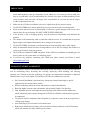
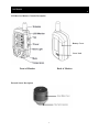
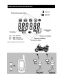
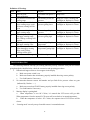
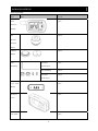
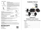
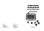
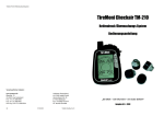
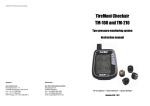
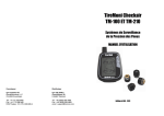
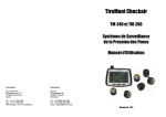
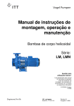
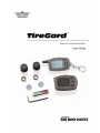
TireGard™ Wireless Tire Pressure Monitoring System BBP # 13-315U Table of Contents Precautions TireGard™ Features and Benefits Controls LCD Receiver/Monitor Icon Descriptions 1. System Map 2. Setup of LCD Receiver/Monitor 3. Installation of the External Sensors Anti –Theft Ring for Sensors (installation is optional) Operation Instructions 1. LCD Receiver/Monitor Basic Functions 2. Advanced Setting Mode Operating Procedures Battery Information Definition of Warnings Troubleshooting Package Contents Product Specifications Warranty 1 2 2 3 4 4 5 6 8 9 9 9 11 11 12 12 13 14 14 PRECAUTIONS 1. Sensors will work with all valve stems – However, rubber 90° valve stems do not last as long as metal and depending on the age and quality of your rubber 90° valve stem you need to make sure they are in good shape. We do recommend the use of metal valve stems for better durability. Please verify clearance when used with a 90 degree valve stem (Softail, etc.) to clear any and all calipers or other components before use. Make sure the LCD Receiver/Monitor can receive signals from all tire pressure sensors. TireGard™ WTPMS has a unique anti-theft device to prevent the sensors from being stolen. Please confirm that all sensors are fitted tightly. If necessary, spread detergent water on the valve 2. 3. 4. stem to check for any air leakage. DO NOT OVER TIGHTEN SENSORS. If tire pressure is low or dropping quickly, stop the motorcycle immediately and determine the problem. The monitor will automatically make a connection with the sensors. It is normal that tire pressure 5. 6. figures might not be updated immediately due to changes of tire pressure. TireGard™ WTPMS is designed to avoid interfering or being interfered with by other signals. Many environmental factors can cause tire temperature to rise or fall. For example, hot weather or a warm tire will result in rising tire pressures. 7. 8. 9. The LCD Receiver/Monitor is NOT waterproof. If the LCD Receiver/Monitor accidentally gets wet, do not ‘power on’ the system until it is completely dried. 10. If you have any questions concerning your TPMS unit, please contact your Dealer or email [email protected]. TireGard™ FEATURES and BENEFITS The TireGard™ Wireless Tire Pressure Monitoring System (WTPMS) is a powerful and effective tool for maximizing safety, increasing fuel economy, improving vehicle handling, and reducing operating cost. Through its wireless technology, tire pressure and temperature information is displayed instantly on the easy to read Graphic User Interface (LCD Receiver/Monitor) in real time. Do It Yourself installation is quick and easy without any technical knowledge or special equipment for the external sensor models. Wireless technology allows the sensor and monitor to connect automatically. Real-time highly accurate sensor and monitor with powerful Graphic User Interface. Fully adjustable pressure and temperature warning range with vibration and/or audible tone which immediately alerts operator through the LCD Receiver/Monitor of abnormal tire pressure or temperature. Tire pressure and tire temperature data will update every time the sensor on the tire experiences a 1 PSI pressure change. Anti-Theft Ring to prevent removal of external sensor. Both Sensor and Monitor are battery powered with a low battery indicator on the LCD monitor which will instantly alert rider of battery power status. 2 CONTROLS LCD Receiver/Monitor Controls Description Battery Cover Cover Lock Front of Monitor Back of Monitor External Sensor Description 3 LCD RECEIVER/MONITOR ICON DESCRIPTIONS 1. System Map for External Sensors 4 1. Setup of LCD Receiver/Monitor Insert Battery: A. One AAA battery is required. B. To remove battery cover, follow the directions A and B on the picture shown below. C. Insert AAA battery properly. D. After battery is inserted, the LCD Receiver/Monitor will issue a beep as it automatically powers up. E. Reinstall the battery cover onto the LCD Receiver/Monitor making sure the cover is inserted in the groove and slide into place. 5 2. Installation of the External Sensors Each sensor is designed specifically for the tire location as denoted by its number; you have to make sure the sensors are installed in their specified positions. See diagrams on page 4. When inserting the batteries into the sensors, do not mix up the Front (1) and Rear (2) sensor caps. Each sensor is marked on its cap and within its body indicating its position on the motorcycle. Insert Batteries in External Sensors Battery Installation for Tire Pressure External Sensor: A. Remove sensor cap by rotating counter-clockwise. B. When inserting lithium battery make sure battery polarity is correct. Immediately the LCD Receiver/Monitor will receive signals from the corresponding sensors and report the pressure value on the screen. At first, you will find the value shows “00.0”. It is because sensors have not been mounted yet. Note: After removing the battery, you will need to let the system reset. Please allow it to sit for 10 seconds before inserting the battery again. 6 A. Install sensor cap by rotating clockwise (Tighten completely by hand. Do not use a tool). Please ensure the sensors are in the correct (1 and 2) position. Do not mix up sensor caps. Both sensor cap and sensor body have reference marks indicating position. Please verify clearance when used with a 90 degree valve stem (Softail, etc.) to clear any and all calipers or other components before use. 7 Anti –Theft Ring for External Sensors: (installation is optional) Anti –Theft Ring is designed to prevent the possibility of sensors being easily stolen. A. Place the Anti-Theft Ring onto the valve stem. B. Install sensor onto valve stem. Do not over tighten the sensor as it may become damaged. C. Adjust the Anti-Theft Ring position to seat it with the sensor firmly in place. D. Insert the hex socket screw into the Anti-Theft Ring. (Do not exert excessive pressure as damage to the valve may occur.) E. When all of the tire pressure sensors are installed, check for air leaks using detergent water. (Spread detergent water on the valve stem and watch for bubbles.) If the tire pressure sensors and tire valves are properly fitted, no air will be leaking from the system. 8 OPERATING INSTRUCTIONS 1. LCD Receiver/Monitor Basic Functions Set: Pressure Unit Setting Temperature Unit Setting Pressure Warning Value Setting Temperature Warning Value Setting Power switch: On / Off Mute: On / Off Backlight Temperature 2. Advanced Setting Mode Press for 3 seconds to enter advanced setting mode. Make your choices by pressing and these will adjust values up or down. 9 A. Set tire pressure measuring: Four types of pressure measuring units are available; PSI, KPA, BAR and the and kg/cm2. Users can make their own choices by pressing the thermometer button star button . B. Set tire temperature measuring: Adjust setting by pressing the thermometer button and star button for adjusting up or down. Celsius and Fahrenheit are provided. C. Setting low tire pressure: Adjust setting by pressing the thermometer button and star button for adjusting up or down. The default value is 26 PSI. D. Setting high tire pressure: Adjust setting by pressing the thermometer button and star button for adjusting up or down. The default value is 45 PSI. E. Setting tire upper temperature warning value: Adjust setting by pressing the thermometer button and star button for adjusting up or down. + Sensor Learning Mode In the unlikelihood the sensor is broken or missing, the sensor learning mode provides a low cost alternative to replace damaged or lost sensors. These ‘learnable sensors’ are available separately. The LCD Receiver/Monitor can reload new sensors and the system will integrate this sensor information into its system and will overwrite the replaced sensors information. Pressing the power switch and the SET button at the same time for 3 seconds will activate the systems ‘learning mode,’ and TireGard™ will start to recognize the new sensors. Enter learning mode, insert battery into ‘learnable sensor’ immediately the LCD monitor will beep once and finish learning process. 10 Take Front Tire (1) for example The ‘learning mode’ will continue for about 30 seconds and then back to main screen. OPERATING PROCEDURES 1. 2. 3. Initialization Switch on LCD Receiver/Monitor to boot up, LCD Receiver/Monitor will be communicating with sensors and showing the last tire pressure values before the system was turned off. Main Screen After booting up, TireGard™ will enter main screen mode. Most of the time, your system will stay in this mode and respond with the latest figures for both tire pressure and temperature. Automatic Power Off A. After power on, if there is no signal from the sensors for 20 minutes the system will power off. B. The LCD Receiver/Monitor will power off if no signal is received for more than one hour after the last signal update. C. 4. LCD Receiver/Monitor data update will only occur if sensor on tire experiences a 1 PSI pressure change. Abnormal Status Alerts The LCD Receiver/Monitor will beep and vibrate once in 10 seconds and repeat 5 times when: A. B. Tire pressure is below low warning value. Tire pressure is higher than upper warning value. C. Tire temperature is higher than upper warning value. The LCD Receiver/Monitor will show low battery icon when: D. LCD Receiver/Monitor runs out of power. E. Tire pressure sensor runs out of power. BATTERY INFORMATION Under normal conditions, external sensor batteries will last approximately 1~2 years and the LCD Receiver/Monitor battery will last approximately 6 months. (Service life may be shorter, depending on the conditions of use.) When the battery becomes weak, the low battery indicator will appear on the screen. Replace the battery with a new CR1632 lithium battery for the external sensors and the LCD Receiver/Monitor battery can be replaced with a AAA 1.5V. 11 Definition of Warnings Item 1. 2. 3. 4. 5. 6. 7. 8. Status Power on LCD Receiver/Monitor Tire pressure is below lower warning range When tire pressure is below lower warning range, each 1 PSI down, warnings will be given Tire pressure is higher than upper warning range When tire pressure is higher than upper warning range, each 1 PSI up, warnings will be given Tire temperature is higher than upper warning value When tire temperature is higher than upper warning range, each 1 PSI up, warnings will be given Learnable sensor is integrated Purpose To remind rider power is on The warning of low tire pressure The warning of tire pressure getting lower Pattern Beeps once The warning of high tire pressure The warning of tire pressure getting high Beeps for 3 times, vibrating and backlight on. Repeats for 5 times Beeps for 3 times, vibrating and backlight on. Repeats for 5 times The warning of high tire temperature The warning of tire temperature getting high Beeps for 3 times, vibrating and backlight on. Repeats for 5 times Beeps for 3 times, vibrating and backlight on. Repeats for 5 times Finish learning mode Beeps once Beeps for 3 times, vibrating and backlight on. Repeats for 5 times Beeps for 3 times, vibrating and backlight on. Repeats for 5 times TROUBLESHOOTING The following checklist will help you remedy problems you may encounter with your unit. Before going through the checklist below, check the connection and operating procedures. 1. Indications disappear from or do not appear in the display a. Make sure power switch is on. b. Make sure monitor has AAA battery properly installed observing correct polarity. 2. 3. 4. c. Use fresh batteries if necessary. No connection between sensors and monitor and you find all tire pressure values are gone (indicated by 3 dashes ‘---‘.) a. Make sure sensor has CR1632 battery properly installed observing correct polarity. b. Use fresh batteries if necessary. Monitor display is getting dark. a. When temperature is over 80° Celsius, it is natural that LCD screen will get dark. When temperature is back to normal, LCD screen will revert back to its normal appearance. b. When the temperature is below -20° Celsius, the response time of LCD screen will be slower. ‘Learning mode’ can only accept ‘learnable sensors’ not standard sensor. 12 PACKAGE CONTENTS Items in package. Item Photo 13-315U LCD 1 piece Receiver/ Monitor Tire 2 pieces Pressure External Sensor CR1632 2 pieces Battery Anti- Hex Head 1 piece Theft Ring Allen Wrench Anti-Theft Ring 2 pieces Hex Head 2 pieces Socket Screw 1.5V AAA 1 piece Battery Protective 1 piece Cover User Guide 1 piece 13 PRODUCT SPECIFICATIONS Tire Pressure External Sensor Specifications Frequency 433.92MHz Tire Pressure Range 0 ~ 60PSI Accuracy Tire Pressure ±1 PSI / Tire Temperature ±2°C Operating Voltage 3V DC Operating Temperature -40°C~125°C Battery Life 1~2 years (Approximately) Dimensions Diameter 20.5mm x Height 20mm Weight 10g ± 1g LCD Receiver/Monitor Specifications Frequency 433.92MHz Operating Voltage 1.5V DC Battery Life 6 months (Approximately) Operating Temperature -20°C~80°C Dimensions Length 58mm x Width 36mm x Height 19mm Weight 43g WARRANTY Big Bike Parts® warrants its Show Chrome Accessories® merchandise shall be free from defective material and workmanship under normal use and service for a period of one year from date of purchase. This warranty does not apply to any merchandise that has been modified or becomes defective as a result of improper use or mistreatment of the merchandise. This warranty is in lieu of any other expressed or implied warranty on the part of Big Bike Parts® or anyone else. Big Bike Parts® shall not be liable for any consequential or incidental damage arising out of the breach of any warranties of its merchandise. 2300 Pioneer Ave. Rice Lake, WI 54868 Phone: 888-BIG-BIKE Fax: 715-234-6872 Scan code with your smartphone to view video Email: [email protected] Website: www.bigbikeparts.com 14