1
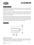
110D
➤Owner’s/Installation
Guide
limited lifetime consumer warranty
For a period of one calendar year from the date of purchase of this auto-security device,
Directed Electronics, Inc. promises to the ORIGINAL PURCHASER to repair or replace
(with a comparable reconditioned model), free of cost, any electronic control module
which proves to be defective in workmanship or material under normal use, SO LONG
AS THE SYSTEM WAS SOLD, INSTALLED, AND SERVICED BY A PROFESSIONAL AUTO INSTALLER, AND REMAINS IN THE CAR IN WHICH THE SYSTEM WAS ORIGINALLY INSTALLED. If warranty service is necessary you must have
a clear copy of your sales receipt containing all of the information shown on the following page.
After the first calendar year, from the date of purchase of this auto-security device,
Directed Electronics, Inc., promises to the ORIGINAL PURCHASER to repair or replace
(with a comparable reconditioned model) any electronic control module which proves to
be defective in workmanship or material under normal use FOR A CHARGE OF $45.00,
SO LONG AS THE SYSTEM WAS SOLD, INSTALLED, AND SERVICED BY A
PROFESSIONAL AUTO INSTALLER, AND REMAINS IN THE CAR IN WHICH
THE SYSTEM WAS ORIGINALLY INSTALLED. If warranty service is necessary you
must have a clear copy of your sales receipt containing all of the information shown on
the following page.
This warranty contains the entire agreement relating to warranty and supersedes all previous and contemporaneous representations or understandings, whether written or oral.
IN ANY EVENT, DIRECTED ELECTRONICS, INC. IS NOT LIABLE FOR THE
THEFT OF THE VEHICLE AND/OR ITS CONTENTS.
This warranty is void if the product has been damaged by accident, unreasonable use,
neglect, improper service or other causes not arising out of defects in materials or construction. This warranty is nontransferable and does not apply to any unit that has been
modified or used in a manner contrary to its intended purpose and does not cover batteries. The unit in question must be returned to the manufacturer, postage prepaid. This
warranty does not cover labor costs for the removal, diagnosis, troubleshooting or reinstallation of the unit. For service on an out-of-warranty product a flat rate fee by model is
charged. Contact your authorized dealer to obtain the service charge for your unit.
These systems are a deterrent against possible theft. Directed Electronics, Inc. is not offering a guarantee or insuring against the theft of the automobile or its contents and disclaims any liability for the theft of the vehicle and/or its contents. Directed Electronics
does not authorize any person to create for it any other obligation or liability in connection with this security system.
© 2003 directed electronics, inc.
i
TO THE MAXIMUM EXTENT ALLOWED BY LAW, ANY AND ALL WARRANTIES ARE EXCLUDED BY THE MANUFACTURER AND EACH ENTITY
PARTICIPATING IN THE STREAM OF COMMERCE THEREWITH. THIS
EXCLUSION INCLUDES BUT IS NOT LIMITED TO THE EXCLUSION OF ANY
AND ALL WARRANTY OF MERCHANTABILITY AND/OR ANY AND ALL WARRANTY OF FITNESS FOR A PARTICULAR PURPOSE AND/OR ANY AND ALL
WARRANTY OF NON-INFRINGEMENT OF PATENTS, IN THE UNITED
STATES OF AMERICA AND/OR ABROAD. NEITHER THE MANUFACTURER
OR ANY ENTITIES CONNECTED THEREWITH SHALL BE RESPONSIBLE OR
LIABLE FOR ANY DAMAGES WHATSOEVER, INCLUDING BUT NOT LIMITED TO ANY CONSEQUENTIAL DAMAGES, INCIDENTAL DAMAGES, TOWING, REPAIR, REPLACEMENT, DAMAGES FOR LOSS OF TIME, LOSS OF
EARNINGS, COMMERCIAL LOSS, LOSS OF ECONOMIC OPPORTUNITY
AND THE LIKE. NOTWITHSTANDING THE ABOVE, MANUFACTURER
DOES OFFER A LIMITED WARRANTY TO REPLACE OR REPAIR THE CONTROL MODULE AS DESCRIBED ABOVE. Some states do not allow limitations on
how long an implied warranty will last or the exclusion or limitation of incidental or consequential damages. This warranty gives you specific legal rights, and you may also have
other rights which vary from state to state.
IMPORTANT NOTE:
This product warranty is automatically void if its date code or serial number is defaced,
missing, or altered. This warranty will not be valid unless you have completed the warranty card and mailed it to Directed Electronics, Inc. within 10 days after purchase to the
address listed on the warranty registration card.
Make sure you have all of the following information from your dealer:
A clear copy of the sales receipt, showing the following:
➤
➤
➤
➤
➤
➤
➤
➤
➤
ii
Date of purchase
Your full name and address
Authorized dealer's company name and address
Type of keyless entry installed
Year, make, model and color of the automobile
Automobile license number
Vehicle identification number
All security options installed on automobile
Installation receipts
© 2003 directed electronics, inc.
table of contents
limited lifetime consumer warranty . . . . . . . . . . . . . . . . . . . . . . . . . . . . . . . . . . . . . . . . i
what is included . . . . . . . . . . . . . . . . . . . . . . . . . . . . . . . . . . . . . . . . . . . . . . . . . . . . . . 2
installation tools . . . . . . . . . . . . . . . . . . . . . . . . . . . . . . . . . . . . . . . . . . . . . . . . . . . . . . 2
important information . . . . . . . . . . . . . . . . . . . . . . . . . . . . . . . . . . . . . . . . . . . . . . . . . 3
system maintenance . . . . . . . . . . . . . . . . . . . . . . . . . . . . . . . . . . . . . . . . . . . . . . 3
your warranty . . . . . . . . . . . . . . . . . . . . . . . . . . . . . . . . . . . . . . . . . . . . . . . . . . . 4
fcc/id notice . . . . . . . . . . . . . . . . . . . . . . . . . . . . . . . . . . . . . . . . . . . . . . . . . . . . 4
primary harness (H1), 12-pin connector . . . . . . . . . . . . . . . . . . . . . . . . . . . . . . . . . . . 5
relay harness (H2), 6-pin connector . . . . . . . . . . . . . . . . . . . . . . . . . . . . . . . . . . . . . . . 6
installation . . . . . . . . . . . . . . . . . . . . . . . . . . . . . . . . . . . . . . . . . . . . . . . . . . . . . . . . . . 7
step 1 . . . . . . . . . . . . . . . . . . . . . . . . . . . . . . . . . . . . . . . . . . . . . . . . . . . . . . . . . 8
step 2 . . . . . . . . . . . . . . . . . . . . . . . . . . . . . . . . . . . . . . . . . . . . . . . . . . . . . . . . . 9
step 3 . . . . . . . . . . . . . . . . . . . . . . . . . . . . . . . . . . . . . . . . . . . . . . . . . . . . . . . . 10
step 4 . . . . . . . . . . . . . . . . . . . . . . . . . . . . . . . . . . . . . . . . . . . . . . . . . . . . . . . . 12
step 5 . . . . . . . . . . . . . . . . . . . . . . . . . . . . . . . . . . . . . . . . . . . . . . . . . . . . . . . . 13
step 6 . . . . . . . . . . . . . . . . . . . . . . . . . . . . . . . . . . . . . . . . . . . . . . . . . . . . . . . . 14
step 7 . . . . . . . . . . . . . . . . . . . . . . . . . . . . . . . . . . . . . . . . . . . . . . . . . . . . . . . . 30
step 8 . . . . . . . . . . . . . . . . . . . . . . . . . . . . . . . . . . . . . . . . . . . . . . . . . . . . . . . . 30
step 9 . . . . . . . . . . . . . . . . . . . . . . . . . . . . . . . . . . . . . . . . . . . . . . . . . . . . . . . . 31
step 10 . . . . . . . . . . . . . . . . . . . . . . . . . . . . . . . . . . . . . . . . . . . . . . . . . . . . . . . 32
transmitter functions . . . . . . . . . . . . . . . . . . . . . . . . . . . . . . . . . . . . . . . . . . . . . . . . . 32
standard configuration . . . . . . . . . . . . . . . . . . . . . . . . . . . . . . . . . . . . . . . . . . . 33
transmitter/receiver learn routine . . . . . . . . . . . . . . . . . . . . . . . . . . . . . . . . . . . . . . . . 34
operating settings learn routine . . . . . . . . . . . . . . . . . . . . . . . . . . . . . . . . . . . . . . . . . 37
to access another feature . . . . . . . . . . . . . . . . . . . . . . . . . . . . . . . . . . . . . . . . . . 38
to exit the learn routine. . . . . . . . . . . . . . . . . . . . . . . . . . . . . . . . . . . . . . . . . . . 38
features menu . . . . . . . . . . . . . . . . . . . . . . . . . . . . . . . . . . . . . . . . . . . . . . . . . . . . . . 39
feature descriptions . . . . . . . . . . . . . . . . . . . . . . . . . . . . . . . . . . . . . . . . . . . . . . . . . . 40
using your system . . . . . . . . . . . . . . . . . . . . . . . . . . . . . . . . . . . . . . . . . . . . . . . . . . . 42
locking with transmitter . . . . . . . . . . . . . . . . . . . . . . . . . . . . . . . . . . . . . . . . . . 42
unlocking without transmitter . . . . . . . . . . . . . . . . . . . . . . . . . . . . . . . . . . . . . 42
ignition-controlled door locks . . . . . . . . . . . . . . . . . . . . . . . . . . . . . . . . . . . . . . 42
turn-off system with Valet/Program switch . . . . . . . . . . . . . . . . . . . . . . . . . . . . 42
panic mode . . . . . . . . . . . . . . . . . . . . . . . . . . . . . . . . . . . . . . . . . . . . . . . . . . . . 43
silent mode . . . . . . . . . . . . . . . . . . . . . . . . . . . . . . . . . . . . . . . . . . . . . . . . . . . . 43
code hopping ™ re-synchronize . . . . . . . . . . . . . . . . . . . . . . . . . . . . . . . . . . . . . . . . 43
system expansion items . . . . . . . . . . . . . . . . . . . . . . . . . . . . . . . . . . . . . . . . . . . . . . . 44
glossary of terms . . . . . . . . . . . . . . . . . . . . . . . . . . . . . . . . . . . . . . . . . . . . . . . . . . . . 45
wiring quick reference diagram . . . . . . . . . . . . . . . . . . . . . . . . . . . . . . . . . . . . . . . . . 46
notes . . . . . . . . . . . . . . . . . . . . . . . . . . . . . . . . . . . . . . . . . . . . . . . . . . . . . . . . . . . . . 47
© 2003 directed electronics, inc.
1
what is included
➤
Control Module
➤
Two 3-Button Transmitters
➤
12-Pin H/1 Main Harness
➤
6-Pin H/2 Secondary Harness
➤
Plug-in Status LED
➤
Plug-in Valet®/Program Button
installation tools
➤
Digital Multi-Meter
➤
Drill
➤
9
➤
Screwdrivers
/32 and 5/16 Drill Bits
(Phillips and Flathead)
➤
Wire Stripper
➤
Solder Iron
➤
Electrical Tape
➤
Pliers
➤
Crimping Tool
note: The installation tools required will vary depending
on your vehicle.
2
© 2003 directed electronics, inc.
important information
Congratulations on the purchase of your keyless entry with security features. This system will allow convenient access to your
vehicle with the push of a button, as well as other optional
features. Properly installed, this system will provide years of
trouble-free operation.
Please take the time to carefully read this Owner’s/Install Guide
in its entirety and watch the Rattler Do-It-Yourself Installation
Video prior to installing your system.
You can print additional or replacement copies of this manual by
accessing the Directed web site at www.diyrattler.com.
important! If you are not comfortable working with electronics or unfamiliar with the tools required, please contact your local dealer for advice or ask to have the system
professionally installed to avoid costly damages. Failure
to properly install the system may result in property damage, personal injury, or both.
➜ system maintenance
The system requires no specific maintenance. Your transmitter is
powered by a miniature 3-volt battery (type CR2032) that will
last approximately one year under normal use. When the battery
begins to weaken, operating range will be reduced.
© 2003 directed electronics, inc.
3
➜ your warranty
Your warranty registration must be completely filled out and
returned within 10 days of purchase. Your product warranty
will not be validated if your warranty registration is not returned.
Please note that it is necessary to keep your proof of purchase.
➜ fcc/id notice
This device complies with Part 15 of FCC rules. Operation is
subject to the following conditions: (1) This device may not
cause harmful interference, and (2) This device must accept any
interference received, including interference that may cause
undesirable operation.
Changes or modifications not expressly approved by the party
responsible for compliance could void the user's authority to
operate this device.
4
© 2003 directed electronics, inc.
primary harness (H1),
12-pin connector
H1/1
ORANGE
H1/2
WHITE
H1/3
WHITE/BLUE
H1/4
BLACK/WHITE
H1/5
NOT USED
H1/6
BLUE
H1/7
NOT USED
H1/8
BLACK
H1/9
YELLOW
(+) Ignition Input, Zone 5
H1/10
BROWN
(-) Horn Output
H1/11
RED
H1/12
RED/WHITE
© 2003 directed electronics, inc.
(-) 500 mA Ground-When-Armed Output
(+) Light Flash Output
(-) 200 mA Channel 3 Validity Output
(-) 200 mA Dome light Supervision Output
(-) 2nd Unlock
(-) Chassis Ground Input
(+) 12V Constant Power Input
(-) 200mA Channel 2 Validity Output
5
relay harness (H2),
6-pin connector
H2/1
WHITE/BLACK
Lock #87A Normally Closed
H2/2
GREEN/BLACK
Lock #30 Common–Output
H2/3
VIOLET/BLACK*
Lock #87A Normally Open–Input
H2/4
BROWN/BLACK
Unlock #87A Normally Closed
H2/5
BLUE/BLACK
Unlock #30 Common–Output
H2/6
VIOLET
Unlock #87 Normally Open–Input
*note: VIOLET and VIOLET/BLACK are common at
the fuse holder.
6
© 2003 directed electronics, inc.
installation
Be sure to read this section thoroughly and view the Rattler DoIt-Yourself Installation Video in its entirety before starting the
installation. Pay special attention to all warnings to prevent
personal injury or damage to your vehicle.
www.diyrattler.com) to get
Visit our 24-hour technical Web site (w
a vehicle-specific wiring guide prior to starting this installation. If
at any time during the installation you are unable to answer your
questions on the Web site, call 1-800-873-1314 for live technical
assistance.
warning! On vehicles with air bags or supplemental restraint systems (SRS) you may
notice a bright yellow tube with small wires
in it marked SRS underneath the steering
column near the key cylinder. DO NOT
tamper or unplug these for any reason to
prevent costly damages to your vehicle or
personal injury. Tampering may cause
unintended deployment of airbags.
warning! DO NOT use any testing tool
other than a digital multi-meter to prevent
costly damages to your vehicle. Use of a test
light may cause grounding of sensitive electrical components that can damage the onboard vehicle computer and processors
resulting in substantial cost for replacement.
warning! Verify that the vehicle transmission is set to park and that the parking
brake is set before beginning installation.
© 2003 directed electronics, inc.
7
➜ step 1
Plug-in LED and Valet/Program switch
The LED and the Valet®/Program switch both plug into the
control module. The status LED plugs into the white two-pin
port, while the Valet®/Program switch should be plugged into
the blue two-pin port. The status LED and Valet®/Program
switch each fit into 9/32–inch holes.
Status LED
Valet/Program Switch
DIA-41
note: The security features consist only of ignition watch
where the horn will honk if the keyless system sees ignition when locked and the security feature is turned on in
the features learned routine.
When mounting the LED it will be necessary to locate an area on
the dash that is visible from all sides of the vehicle, and has at
least 1 inch of clearance behind the mounting area. It is recommended that a factory "pop-out" be used for the LED mounting,
using a 9/32 drill bit drill a hole in the location selected, feed the
LED through the hole, press the LED firmly until it snaps into
place. Run the wires to the selected control module mounting
8
© 2003 directed electronics, inc.
location using caution to NOT run the wires near any moving
objects or excessive heat.
The Valet®/Program switch is usually mounted under the dash
or in the glove box, the same precautions used for the LED
should be followed. Once a location has been selected drill a
9/32 hole, feed the wires through the hole and press the switch
firmly until it snaps into place. Run the wires to the same location as the LED using caution to NOT run the wires near any
moving objects or excessive heat.
➜ step 2
Ground Wire
The BLACK (H1/8) wire on the main 8-pin harness is ground.
This wire should be connected to a clean, paint-free area of metal
in the drivers kick panel area. First strip back a ¾-inch section of
the insulation off the BLACK wire and crimp a ring terminal
(not provided) to that wire. Locate a clean, paint-free metal
surface in the drivers kick panel. Using a self-tapping screw, drill
the screw with the ring terminal to the metal area. Once screwed
down, pull on the wire to ensure a good connection.
note: More problems are attributed to poor ground connections than any other cause. Take extra care to ensure
the ground is clean and secure.
© 2003 directed electronics, inc.
9
SELF-TAPPING
BOLT OR SCREW
GROUND
WIRE
DIA-591
NOTE: REMOVE ANY PAINT
BELOW RING CONNECTOR
RING
CONNECTOR
➜ step 3
Constant Power and Ignition wires
Almost all power and ignition wires can be found behind the key
cylinder under the lower drivers side dash panel. Using the
appropriate hand tools, remove the lower dash panel using care
not to break any parts. If the panel does not come off easily
check for any additional screws you may have missed.
Once the lower dash panel has been removed, locate the ignition
harness at the back of the key cylinder. This is usually a group of
10
© 2003 directed electronics, inc.
thicker wires. With the ignition harness exposed, use your digital
multi-meter to find your power and ignition wires.
Place the black lead of the meter to a clean metal surface in the
kick panel area and secure it. Put the meter in the DC voltage
position, then take the red lead of the meter and probe one of the
thicker gauge wires. The color and identity of your specific
vehicle wiring can be obtained at www.diyrattler.com. With the
key in the OFF position, test the suspect wire. The constant
power wire will read between 11.00 volts and 13.00 volts.
Once the constant power wire has been identified, solder the
RED (H1/11) wire from the 12-pin harness to it and cover the
connection with electrical tape to ensure a safe connection.
With the meter black lead still in the kick panel, locate the ignition wire harness in the same location. It will test differently than
constant (+)12 volts. Locate the suspected wire using the
www.diyrattler.com Web site and place the red lead of the meter
on the suspected wire. With the key in the off position the meter
will read 0.00 volts. Turn the key to the on position and the meter
should read between 11.00 volts and 13.00 volts. Now watching
the meter, turn the key to the crank position and the voltage
should drop a small amount but not disappear. If the voltage
disappears this is not an ignition wire but an accessory wire. If the
wire meters correctly, solder the YELLOW (H1/9) wire from the
12-pin harness to it and cover the connection with electrical tape.
© 2003 directed electronics, inc.
11
➜ step 4
Starter wire
note: Optional 8618 starter kill relay is required.
The starter wire will be located in the same harness as the ignition
and constant power. Leaving the meter black lead connected to
the metal ground.
Find the wire suspected to be the starter wire according to the
web information on your vehicle. Place the red lead of your
meter on the wire. With the key in the off position the meter
should read 0.00 volts and will stay at 0.00 volts in all key positions except the crank position. In the crank position your meter
should read between 10.00 volts and 13.00 volts, and will drop
back to 0.00 volts when the starter disengages. Once you locate
the starter wire, cut the wire in half and try to crank (start) the
vehicle. (Always check the Web site information on your vehicle
for warnings regarding the starter wire and check engine lights.
Some vehicles will trip a check engine light if the starter wire is
cut.) If the vehicle does not crank, the correct wire has been
12
© 2003 directed electronics, inc.
identified.
➜ step 5
Parking light flash
There are several different types of parking light circuits. The
following description is for a standard positive-triggered parking
light circuit, usually located at the light switch. If the web vehicle
information suggests a different type of parking light circuit,
please contact Rattler Technical Support.
Using the web information on the vehicle, locate the suspected
wire and place the BLACK lead of the meter to a ground and
secure it. Place the multi-meter in the DC position. Using the
RED lead of the meter, probe the wire. With the light switch in
the off position the meter will read 0.00 volts. While watching
the meter, turn the switch to the parking light position. The
meter will read between 10.00 volts and 13.00 volts.
© 2003 directed electronics, inc.
13
important: While reading the meter turn (adjust) the
dash dimmer control switch. The voltage should not vary
on the meter. If the voltage does vary the incorrect suspected wire has been tested. Find the correct wire and
retest.
Once you have identified the correct wire, solder the WHITE
(H1/2) wire on the main connector to it and cover the connection with electrical tape.
➜ step 6
Door locks
The system comes with a built in relay pack for door lock operation. When attempting to interface the power door locks with
your system it is important to understand that there are multiple
types of door locking systems in today's vehicles. To determine
your vehicle’s power door lock system, check the web information
on your vehicle.
If your door lock system is a different type than described in this
guide, go to www.diyrattler.com to download the door lock
14
© 2003 directed electronics, inc.
guide. The door lock guide identifies the type of system for your
vehicle. With the built in door lock relays you can properly
interface the power locks with your security system. If you are
unable to identify your door lock system with the web information please contact Rattler Technical Support.
Although there are numerous types of door lock circuits, the
most common is the negative triggered door lock system. If your
vehicle has a negative triggered door lock system, follow the steps
below. If your vehicle has any other type of door lock system
then, the easiest way to determine which type of door lock
system you are working with is to remove the master locking
switch itself, which is usually on the driver’s door or on the
center console. Once you have determined which type of factory
door lock circuit you are working with, and the color codes of
the switch wires to be used, you can usually simplify the installation by locating the same wires in the vehicle’s kick panel. If no
central locking switch is found, the installation may require a
door lock actuator.
note: Always retest the wires in the kick panel to be sure
they function the same way as the wires on the switch.
There are eight common types of door lock circuits (some vehicles use more unusual systems):
© 2003 directed electronics, inc.
15
■ Type A: Three-wire (+) pulse controlling factory lock relays.
Most GM, some Ford and Chrysler, 1995 Saturn, some new
VW, newer BMW.
■ Type B: Three-wire (-) pulse controlling factory lock relays.
Most Asian vehicles, early Saturn, some BMW and Porsche.
■ Type C: Direct-wired reversing-polarity switches. The switches are wired directly to the motors. This type of system has no
factory relays. Most Fords, many GM two-doors cars and trucks,
many Chryslers.
■ Type D: Adding one or more aftermarket actuators. These
include slave systems without an actuator in the driver’s door,
but with factory actuators in all the other doors. Type D also
includes cars without power locks, which will have actuators
added. All Saabs before 1994, all Volvo except 850i, all Subaru,
most Isuzu, and many Mazdas. Some mid-eighties Nissans, pre1985 Mercedes-Benz and Audi.
■ Type E: Electrically-activated vacuum systems. The vehicle
must have a vacuum actuator in each door. Make sure that locking the doors from the driver's or passenger side using the key
activates all the actuators in the vehicle. This requires a slight
modification to the door lock harness. Mercedes-Benz and Audi
1985 and newer.
■ Type F: One-wire system - cut to lock, ground to unlock. This
system is found in late-model Nissan Sentras, some Nissan
240SX, and Nissan 300ZX 1992 and later. It is also found in
older Mitsubishis, and some early Mazda MPV’s.
■ Type G: Positive (+) multiplex. This system is most common16
© 2003 directed electronics, inc.
ly found in Ford, Mazda, Chrysler and GM vehicles. The door
lock switch or door key cylinder may contain either one or two
resistors.
■ Type H: Negative (-) multiplex. The system is most commonly found in Ford, Mazda, Chrysler and GM vehicles. The door
lock switch or door key cylinder may contain either one or two
resistors.
at the switch
■ Three-wire switches will have either a constant ground input or
a constant (+)12V input, along with the pulsed lock and unlock
outputs to the factory relays.
■ Many BMW’s and VW’s have no external switch. The switches
are inside the actuator, and instead of pulsing, the proper wires
will flip-flop from (+)12V to (-) ground as the door locks are
operated.
■ Direct-wired switches will have a (+)12V constant input and one
or two (-) ground inputs, along with two output leads going
directly to the lock motors.
© 2003 directed electronics, inc.
17
type A: positive-triggered, relay-driven system
18
© 2003 directed electronics, inc.
type B: negative-triggered, relay-driven system
This system is common in many Toyota, Nissan, Honda, and
Saturn models, as well as Fords with the keyless-entry system
(some other Fords also use Type B).
The switch will have three wires on it, and one wire will test
ground all the time. One wire will pulse (-) when the switch
locks the doors, and the other wire will pulse (-) when the switch
unlocks the doors. This type of system is difficult to mistake for
any other type.
© 2003 directed electronics, inc.
19
type C: direct-wired, reversing-polarity system
testing reversing polarity systems
Use these instructions if the power door lock switch has four or
five heavy-gauge wires. This type of switch has two outputs that
rest at (-) ground.
important: To interface with these systems, you must cut
two switch leads. The relays must duplicate the factory
door lock switches’ operation. The master switch will
have one or two ground inputs, one (+)12V input, and
two switch outputs going directly to the slave switch and
through to the motors. These outputs rest at (-) ground.
The lock or unlock wire is switched to (+)12V, while the
other wire is still grounded, thus completing the circuit
and powering the motor. This will disconnect the switch
from the motor before supplying the motor with (+)12V,
avoiding sending (+)12V directly to (-) ground.
20
© 2003 directed electronics, inc.
It is critical to identify the proper wires and locate the master
switch to interface properly. Locate wires that show voltage when
the switch is moved to the lock or unlock position. Cut one of
the suspect wires and check operation of the locks from both
switches. If one switch loses all operation in both directions then
you have cut one of the correct wires and the switch that is
entirely dead is the master switch. If both switches still operate
in any way and one or more door motors have stopped
responding entirely, you have cut a motor lead. Reconnect it and
continue to test for another wire. Once both wires have been
located and the master switch identified, cut both wires and
interface as described in the following paragraphs.
caution: If these wires are not connected properly, you
will send (+)12V directly to (-) ground, possibly damaging the alarm or the factory switch.
■ H2/A WHITE/BLACK: Once both door lock wires are
located and cut, connect the white/black wire to the master
switch side of the lock wire. The master switch side will show
(+)12V when the master switch is operated to the lock position
and (-) ground when the master switch is in the middle position.
■ H2/B GREEN/BLACK: Connect the green/black wire to
the other side of the lock wire. This is the motor side of the lock
wire and it goes to the lock motor through the slave switch.
■ H2/C VIOLET/BLACK: This wire must be connected to
a constant (+)12 volts. The best connection point for this wire is
the constant (+)12V supply for the door lock switch*, or directly to the positive (+) battery post with a fuse at the battery post.
© 2003 directed electronics, inc.
21
*note: Except in GM cars with retained accessory power
(RAP). In these vehicles, the (+)12V feed to the door lock
switches is turned off if the doors are closed for any length
of time.
note: Most direct-wired power lock systems require 20-30
amps of current to operate. Connecting the violet/black
wire to a poor source of voltage will keep the door locks
from operating properly.
■ H2/D BROWN/BLACK: Connect the brown/black wire
to the master switch side of the unlock wire. The master switch
side will show (+)12V when the master switch is in the unlock
position and (-) ground when the master switch is in the middle
position.
■ H2/E BLUE/BLACK: Connect the blue/black wire to the
other side of the unlock wire.
22
© 2003 directed electronics, inc.
type D: adding one or more after-market actuators
Vehicles without factory power door locks require the installation of one actuator per door. This requires mounting the door
lock actuator inside the door. Other vehicles may only require
one actuator installed in the driver's door if all door locks are
operated when the driver's lock is used.
note: Adding door lock actuators can be complicated.
Please contact Rattler technical support prior to attempting the addition of actuators.
© 2003 directed electronics, inc.
23
type E: electrically-activated vacuum
This system is found in Mercedes-Benz and Audi 1985 and
newer. The door locks are controlled by an electrically activated
vacuum pump. The control wire will show (+)12V when doors
are unlocked and (-) ground when locked.
note: The system must be programmed for 3.5-second
door lock pulses, and the violet jumper between the #87
lock terminal and the #87 unlock terminal must be cut.
Contact Rattler technical support.
24
© 2003 directed electronics, inc.
type F: one-wire system (cut to lock, ground to unlock)
This type of door lock system usually requires a negative pulse to
unlock, and cutting the wire to lock the door. (With some vehicles, these are reversed.) It is found in the late-model Nissan
Sentras, some Nissan 240SX, Nissan 300ZX 1992 and later. It is
also found in some Mazda MPV's.
note: The violet jumper between the #87 lock terminal
and the #87 unlock terminal must be cut.
© 2003 directed electronics, inc.
25
type G: positive (+) multiplex
This system is most commonly found in Ford, Mazda, Chrysler
and GM vehicles. The door lock switch or door key cylinder
may contain either one or two resistors.
SINGLE-RESISTOR TYPE: If one resistor is used in the door
lock switch/key cylinder, the wire will pulse (+)12V in one direction and less than (+)12V when operated in the opposite direction.
TWO-RESISTOR TYPE: If two resistors are used in the factory
door lock switch/key cylinder, the switch/key cylinder will read
less than (+)12V in both directions.
DETERMINING THE PROPER RESISTOR VALUES: To
determine the resistor values, the door lock switch/key cylinder
must be isolated from the factory door lock system. For testing, use
a calibrated digital multimeter that is set to ohms.
IMPORTANT: To ensure an accurate resistance reading, do not touch
the resistor or leads during testing.
1.
Cut the output wire from the door lock switch/key cylinder in
half.
2.
Test with the meter from the switch side of the cut door lock
switch/key cylinder wire to a reliable constant (+)12V source.
Some good constant (+)12V references are the power input
source to the door lock switch/key cylinder, the ignition switch
power wire, or the (+) terminal of the battery.
26
© 2003 directed electronics, inc.
3.
Operate the door lock switch/key cylinder in both directions to
determine the resistor values. If the multimeter displays zero
resistance in one direction, no resistor is needed for that direction.
4.
Once the resistor value(s) is determined, refer to the wiring diagram for proper wiring.
type H: negative (+) multiplex
The system is most commonly found in Ford, Mazda, Chrysler
and GM vehicles. The door lock switch or door key cylinder
may contain either one or two resistors.
SINGLE-RESISTOR TYPE: If one resistor is used in the door
lock switch/key cylinder, the wire will pulse ground in one direction and resistance to ground when operated in the opposite
direction.
© 2003 directed electronics, inc.
27
TWO-RESISTOR TYPE: If two resistors are used in the factory
door lock switch/key cylinder, the door lock switch/key cylinder
will read resistance to ground in both directions.
DETERMINING THE PROPER RESISTOR VALUES: To
determine the resistor values, the door lock switch/key cylinder
must be isolated from the factory door lock system. For testing, use
a calibrated digital multimeter that is set to ohms.
IMPORTANT: To ensure an accurate resistance reading, do not touch
the resistor or leads during testing.
1.
Cut the output wire from the door lock switch/key cylinder in
half.
2.
Test with the meter from the switch side of the cut door lock
switch/key cylinder wire to a reliable ground source. Some good
ground references are the ground input source to the door lock
switch/key cylinder or the battery ground.
3.
Operate the door lock switch/key cylinder in both directions to
determine the resistor values. If the multimeter displays zero
resistance in one direction, no resistor is needed for that direction.
4.
Once the resistor value(s) is determined, refer to the wiring diagram for proper wiring.
28
© 2003 directed electronics, inc.
Locate the suspected lock wire, and with the red meter lead still
secured to a (+)12 volt source, probe the suspect wire with the
black lead of the meter. Press the door lock switch to the lock
position and watch the meter display. The correct wire will show
a 10.00 to 12.00 volt pulse when the switch is pressed.
note: Additional parts may be required to interface with
certain door lock types.
The Rattler Do-It-Yourself system comes with on board relays.
© 2003 directed electronics, inc.
29
➜ step 7
Horn Honk
This wire provides a negative pulsed output for audible confirmation of the door locks through the horn. Locate the suspected
horn wire using the information sheet for your specific vehicle.
With the red lead of the meter attached to a 12-volt constant
source, connect the black lead to the suspect horn wire and honk
the horn. The meter should read between 11.00 and 12.00 volts.
Once the horn wire has been identified, strip off enough insulation off this wire to solder the BROWN (H1/10) wire from the
12-pin main harness to the horn wire and cover the solder
connection with black tape.
note: The BROWN (H1/10) wire is a low current output. It is intended only to drive a relay which controls the
horn. Connecting this wire directly to the horn will result
in damage to the keyless entry system.
➜ step 8
Dome light supervision (optional)
The dome light wire is optional and not required for normal
operation, however if desired you can have the security system
turn on the dome light when the system is disarmed. If you
would like this feature please refer to the web site or call technical support.
30
© 2003 directed electronics, inc.
➜ step 9
Optional connections (channels 2 and 3)
When the system receives the code controlling channel 2, for
longer than 1.5 seconds, the RED/WHITE wire (H1/12channel 2) will supply an output as long as the transmission
continues. This is often used to operate a trunk/hatch release or
other relay-driven function.
When the system receives the code controlling channel 3, the
output is instantaneous, and the WHITE/BLUE wire (H1/3channel 3) will supply an output as long as the transmission
continues. This is used to operate an accessory function.
important: Never use these wires to drive anything but a
relay or a low-current input! The transistorized output
can only supply 200 mA of current. Connecting directly
to a solenoid, motor, or other high-current device will
cause it to fail.
© 2003 directed electronics, inc.
31
➜ step 10
Testing the system
With all the previous steps completed, the operation of the
system can now be tested.
Close all the doors and press the
button on the transmitter
to lock the doors, the system should honk the horn once and the
parking lights should flash once. Press the
button on the
transmitter to unlock the doors. The horn should honk twice
and the parking lights should flash twice.
This completes the testing, if all functions do not work correctly
check your wiring against the manual and verify all connections.
If you still are experiencing problems contact Rattler technical
support.
transmitter functions
The receiver uses a computer-based learn routine to learn the
transmitter buttons. This makes it possible to assign any specific
transmitter button, or combination of buttons, to any receiver
function. The transmitter initially comes programmed in the
Standard Configuration, but may also be customized by an
authorized dealer. Unless otherwise specified, the buttons used
in all of the instructions in this manual correspond to a Standard
Configured transmitter.
32
© 2003 directed electronics, inc.
➜ standard configuration
Button
The door locking and unlocking function are controlled by
pressing
.
Button
This channel 2 accessory
is used for trunk release.
Button
This channel 3 accessory
is an additional channel for optional
accessory functions such as remote start.
© 2003 directed electronics, inc.
33
transmitter/receiver
learn routine
The system comes with 2 transmitters that have been taught to
the receiver. The receiver can store up to 4 different transmitter
codes in memory. Use the following learn routine to add transmitters to the system or to change button assignments if desired.
The Disarm/Program switch, plugged into the blue port, is used for
programming. There is a basic sequence of steps to remember whenever programming this unit: Key, Choose, Transmit and Release.
1. Key. Turn the ignition to the ON position.
2. Choose. Within 10 seconds, press and
release the Disarm/Program switch the
number of times for the desired function (see
chart below). Then press the switch once more
and hold it. The horn will honk and the LED
will flash to confirm the selected channel. Do
not release the Disarm/Program switch.
34
© 2003 directed electronics, inc.
Channel number
Function
1
Auto Learn—all buttons
2
Lock/Unlock
3
Channel 2 Output
(1.5 sec delay)
4
Channel 3/Instant
output
5
Delete all Transmitters
3. Transmit. While holding the Disarm/
Program switch, press the desired button to be
programmed on the transmitter.
4. Release. Once the button is learned, the
horn will honk, confirming transmitter
programming. The Valet/Program switch can
now be released.
© 2003 directed electronics, inc.
35
Auto Learn function
This function provides a 1–step programming of the transmitter
to the following factory default settings:
➤
Button
—Lock/Unlock
➤
Button
—Channel 2 output
➤
Button
—Channel 3/Instant output
note: All programmable features will be reset to factory
default settings.
Delete all Transmitters
In case the transmitter(s) is lost or stolen, this function provides
removal of all transmitter(s) access from the system memory.
Learn Routine will be exited if:
36
➤
Ignition is turned off.
➤
Program switch is pressed too many times.
➤
More than 15 seconds elapses between programming steps.
© 2003 directed electronics, inc.
operating settings learn routine
Many of the operating settings of this unit are programmable.
They can be changed whenever necessary through the Operating
Settings Learn Routine™. The Valet/Program push-button
switch, plugged into the blue port, is used together with a
programmed transmitter to change the settings.
To enter the System Features Learn Routine™:
1. Ignition. Turn the ignition on, then back off.
(The H1/9 YELLOW switched ignition input
must be connected.)
2.
Choose. Within 10 seconds, press and
release the Disarm/Program switch the number
of times for the desired feature (see chart
below). Then press the switch once more and
hold it. The horn will honk and the LED will flash to confirm
the selected feature. Do not release the Disarm/Program switch.
3.
Transmit. While HOLDING the
Valet/Program switch, you can select the
desired feature settings using the transmitter.
Pressing Button
while HOLDING down
the Valet/Program switch will program the feature to the LED
ON settings. The siren will chirp once to indicate the one-chirp
setting has been selected. Pressing Button
while HOLD -
ING down the Valet/Program switch will change the setting to
© 2003 directed electronics, inc.
37
the LED OFF setting. The siren will chirp twice indicating that
the LED OFF setting has been selected.
4. Release. Release the Valet/Program switch.
➜ to access another feature
You can advance from feature to feature by pressing and
releasing the Valet/Program switch the number of times necessary to get from the feature you just programmed to the feature
you wish to access. For example, if you just programmed Feature
1 and you want to program Feature 2:
1.
Release the Valet/Program switch.
2.
Press and release the Valet/Program switch ONCE to
advance from Feature 1 to Feature 2.
3.
Press the Valet/Program switch once more and HOLD it.
4.
The horn will honk and the LED will flash two times to
confirm that you have accessed the door lock pulse duration
(feature 2).
➜ to exit the learn routine
To exit the learn routine, do one of the following:
1.
38
Turn the ignition on.
© 2003 directed electronics, inc.
2.
No activity for longer than 15 seconds.
3.
Press the Valet/Program switch at least 7 times.
features menu
The factory defaults are indicated in bold text in the table below.
Feature
Number
Default LED
On Setting
(press transmitter
button 1)
LED Off Setting
(press transmitter
button 2)
1
Ignition-controlled
door locks ON
Ignition-controlled
door locks OFF
2
0.8-second Door Lock
Pulse Duration
3.5-second Door Lock
Pulse Duration
3
Double Pulse
Unlock OFF
Double Pulse
Unlock ON
4
Security Features ON
Security Features OFF
5
Code Hopping ON
Code Hopping OFF
note: The feature number indicates the number of times
the LED will flash. The Factory defaults are indicated in
bold type.
© 2003 directed electronics, inc.
39
feature descriptions
1
IGNITION CONTROLLED DOOR LOCKS ON/OFF:
When turned on, the doors will lock three seconds after the ignition is turned on and unlock when the ignition is turned off.
2
DOOR LOCK PULSE DURATION: Some European vehicles,
such as Mercedes-Benz and Audi, require longer lock and unlock
pulses to operate the vacuum pump. Programming the system to
provide 3.5 second pulses will accommodate door lock interface
in these vehicles. The default setting is 0.8 second door lock
pulses. See Mercedes-Benz and Audi - 1985 and Newer (Type E
Door Locks section) diagram.
3
DOUBLE PULSE UNLOCK OFF/ON: Some vehicles require
two pulses on a single wire to unlock the doors. When the
double pulse unlock feature is turned on, the H2/E
BLUE/BLACK wire will supply two negative pulses instead of a
single pulse. This makes it possible to directly interface with
double pulse vehicles without any extra parts.
4
SECURITY FEATURES ON/OFF: In the ON setting, if the
ignition key is turned ON, the unit will trigger a 30–second triggered sequence (horn and lights). The H1/1 ORANGE groundwhen-armed output will remain active.
In the OFF setting, if the ignition key is turned ON, the trigger
sequence will be disabled. Also, the ground-when-armed output
is turned OFF.
40
© 2003 directed electronics, inc.
5
CODE HOPPING ™ ON/OFF: This system features Code
Hopping™ as an option. Code Hopping™ is a feature that uses a
mathematical formula to change the system’s code each time the
transmitter and receiver communicate. This makes the group of
bits or "word" from the transmitter very long. The longer the
word is, the easier it is to block its transmission to the unit.
Disabling the Code Hopping™ feature lets the receiver ignore
the Code Hopping™ part of the transmitted word. As a result,
the unit may have better range with Code Hopping™ off.
© 2003 directed electronics, inc.
41
using your system
➜ locking with transmitter
To lock the doors press
for one second. The parking lights
will flash once and the horn will honk once to confirm that the
doors are locked.
➜ unlocking without transmitter
To unlock the doors press
for one second. The parking
lights will flash twice and the horn will honk twice to confirm
that the doors are unlocked.
➜ ignition-controlled door locks
If power door locks have been connected to your system and the
ignition-controlled door locks are programmed on, the vehicle's
door will lock three seconds after the ignition has been turned on
and unlock when the ignition is turned off.
➜ turn-off system with Valet/Program switch
Turn the ignition key to the ON position. The press and release
the Valet/Program switch within 15–seconds.
note: The above only functions with security features
programmed ON.
42
© 2003 directed electronics, inc.
➜ panic mode
If you are threatened in or near your vehicle, you can press
for 1.5 seconds to trigger Panic Mode on your keyless entry
system and attract attention. The horn will honk and the
parking lights will flash for 30–seconds. To stop the Panic Mode
at any time, press
again.
➜ silent mode
Use the Silent Mode to temporarily turn off the lock or unlock
horn honks by briefly pressing
before pressing
to
lock/unlock. The confirmation horn honk will then be eliminated for that one operation only.
code hopping ™ re-synchronize
If the transmitter is pressed many times out of range, or the
battery is removed, the transmitter may get temporarily out of
sync and fail to operate the system. To synchronize the transmitter, simply press
several times within range of the
vehicle. The system will automatically synchronize and the transmitter will respond normally.
© 2003 directed electronics, inc.
43
system expansion items
The following items can be added to the system:
➤
Dome light control
➤
Remote start
➤
Window control
➤
Trunk release
2nd unlock
➤
44
© 2003 directed electronics, inc.
glossary of terms
Control Module: The "brain" of your keyless entry system.
Usually hidden underneath the dash area of the vehicle.
LED: A red light mounted inside the vehicle. The LED indicates
the status of your system.
Transmitter: A hand-held, remote control that operates the
various functions of the security system.
Valet/Program Switch: A small, push-button switch mounted
inside the vehicle. This switch is used to override the security
features when a transmitter is lost or damaged. It is also used to
change the system features and program the transmitters.
© 2003 directed electronics, inc.
45
wiring quick reference diagram
46
© 2003 directed electronics, inc.
notes
_________________________________________________
_________________________________________________
_________________________________________________
_________________________________________________
_________________________________________________
_________________________________________________
_________________________________________________
_________________________________________________
_________________________________________________
_________________________________________________
_________________________________________________
_________________________________________________
_________________________________________________
_________________________________________________
_________________________________________________
_________________________________________________
_________________________________________________
_________________________________________________
_________________________________________________
_________________________________________________
_________________________________________________
© 2003 directed electronics, inc.
47
48
© 2003 directed electronics, inc.
✂
✂
To lock the doors using your transmitter
■ Pressing
for one second will lock the doors. The parking lights will
flash once and the horn honks once to confirm the doors are locked.
To unlock the doors using your transmitter
■ To unlock the doors, press
for one second. The parking lights will
flash twice and the horn honks twice to confirm the doors are unlocked.
To disarm the system using the Valet/Program switch
■ Turn the ignition key to the ON position. The press and release the
Valet/Program switch within 15–seconds.
✂
Cut along dotted line and fold for a quick and easy reference to keep in your purse or wallet.
QUICK REFERENCE GUIDE:
QUICK REFERENCE GUIDE:
To lock the doors using your transmitter
■ Pressing
for one second will lock the doors. The parking lights will
flash once and the horn honks once to confirm the doors are locked.
To unlock the doors using your transmitter
■ To unlock the doors, press
for one second. The parking lights will
flash twice and the horn honks twice to confirm the doors are unlocked.
To disarm the system using the Valet/Program switch
■ Turn the ignition key to the ON position. The press and release the
Valet/Program switch within 15–seconds.
50
© 2003 directed electronics, inc.
© 2003 directed electronics, inc.
51
The company behind this system is Directed Electronics, Inc.
Since its inception, Directed Electronics has had one purpose, to provide consumers with
the finest vehicle security and car stereo products and accessories available. The recipient of
nearly 100 patents and Innovations Awards in the field of advanced electronic
technology, DIRECTED is ISO 9001 registered.
Quality Directed Electronics products are sold and serviced throughout North America
and around the world.
Call (800) 274-0200 for more information about our products and services.
Directed Electronics is committed to delivering world class quality products
and services that excite and delight our customers.
Directed Electronics, Inc.
Vista, CA 92081
www.directed.com
© 2003 Directed Electronics, Inc. - All rights reserved
G312R 7-03