1
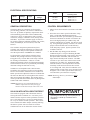
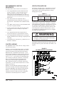
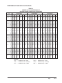
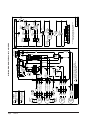
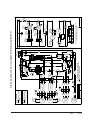
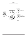
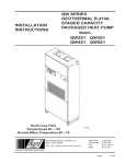
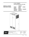
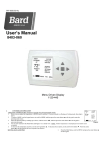
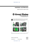
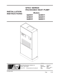
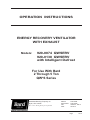
OPERATION INSTRUCTIONS
ENERGY RECOVERY VENTILATOR
WITH EXHAUST
Models:
920-0074 QWSERV
920-0138 QWSERV
with Intelligent Defrost
For Use With Bard
2 Through 5 Ton
QW*S Series
Bard Manufacturing Company, Inc.
Bryan, Ohio 43506
Since 1914...Moving ahead, just as planned.
Manual:2100-533E
Supersedes:2100-533D
File:
Volume II, Tab 14
Date:04-23-14
Manual2100-533E
Page
1 of 12
CONTENTS
Electrical Specifications............................................ 3
General Description.................................................. 3
920-0074 & -0138 with Intelligent Defrost................ 3
Control Requirements.............................................. 3
Recommended Control Sequences......................... 4
Control Wiring........................................................... 4
Ventilation Airflow..................................................... 4
Performance & Application Data........................ 5 & 6
Figures
Figure 1
Figure 2
Figure 3
Figure 4
Blower Speed Adjustment......................... 4
Belt Replacement...................................... 8
Hub Assembly with Ball Bearings.............. 9
Configuring 8403-067 CO2 Control.......... 12
Wiring Diagram
Wiring Diagram for 920-0074 QWSERV................ 10
Wiring Diagram for 920-0138 QWSERV w/I.D....... 11
Tables
Table 1 Ventilation Air (CFM)................................. 4
Table 2 Summer Cooling Performance.................. 5
Table 3 Winter Heating Performance..................... 6
Energy Recovery Ventilator Maintenance ......... 6 & 7
Maintenance Procedures ........................................ 7
BARD MANUFACTURING COMPANY, INC.
BRYAN, OHIO USA 43506
Manual2100-533E
Page 2 of 12
ELECTRICAL SPECIFICATIONS
Model
Voltage
Amps
Control
Voltage
920-0074
920-0138
230 / 208
2.2
24V
Model
For Use with the
Following Units
920-0074
920-0138
QW2S-A, -B, -C
QW3S-A, -B, -C
QW4S-A, -B, -C
QW5S-A, -B, -C
GENERAL DESCRIPTION
CONTROL REQUIREMENTS
The Energy Recovery Ventilator was designed to
provide energy efficient, cost effective ventilation to
meet I. A. Q. (Indoor Air Quality) requirements while
still maintaining good indoor comfort and humidity
control for a variety of applications such as schools,
classrooms, lounges, conference rooms, beauty salons
and others. It provides a constant supply of fresh air
for control of airborne pollutants including CO2, smoke,
radon, formaldehyde, excess moisture, virus and
bacteria.
1. Indoor blower motor must be run whenever the ERV
is run.
The ventilator incorporates patented rotary heat
exchange state-of-the-art technology to remove both
heat & moisture and provides required ventilation to
meet the requirements of ASHRAE 62.1 standard.
It is designed as a single package which is factory
installed. The package consists of a unique rotary
Energy Recovery Cassette that can be easily removed
for cleaning or maintenance. It has two 15-inch
diameter heat transfer wheels for efficient heat transfer.
The heat transfer wheels use a permanently bonded dry
desiccant coating for total heat recovery.
Ventilation is accomplished with 2 blower/motor
assemblies each consisting of a drive motor and dual
blowers for maximum ventilation at low sound levels.
Motor speeds can be adjusted so that air is exhausted at
the same rate that fresh air is brought into the structure
thus not pressuring the building. The rotating energy
wheels provide the heat transfer effectively during both
summer and winter conditions.
2. Select the correct motor speed on the ERV. Using
Table 1 of the ERV Installation Instructions
determine the motor speed needed to get the desired
amount of ventilation air needed. For instance, do
not use the high speed tap on a ERV if only 200
CFM of ventilation air is needed. Use the low speed
tap. Using the high speed tap would serve no useful
purpose and would effect the overall efficiency
of the heat pump system. System operation costs
would also increase.
3. Run the ERV only during periods when the
conditioned space is occupied. Running the ERV
during unoccupied periods wastes energy, decreases
the expected life of the ERV, and can result in a
large moisture buildup in the structure. The ERV
can remove up to 60 to 70% of the moisture in the
incoming air, not 100% of it. Running the ERV
when the structure is unoccupied allows moisture
to build up in the structure because there is little
or no cooling load. Thus, the air conditioner is not
running enough to remove the excess moisture being
brought in. Use a control system that in some way
can control the system based on occupancy.
NOTE:The Energy Recovery Ventilator is NOT a
dehumidifier.
NOTE:Operation is not recommended below 5°F
outdoor temperature because freezing of
moisture in the heat transfer wheel can occur.
920-0138 WITH INTELLIGENT DEFROST
This model is equipped with a thermostat which is
sensing the intake ventilation air. It is factory set to
initiate a defrost sequence when operations are below
10°F. This defrost time is set for a 4-minute defrost
for every 32 minutes of ERV operation. This control
circuit controls the intake damper assembly allowing
the ERV to operate with zero intake air to allow
conditioned room air to defrost the cassette wheels.
IMPORTANT
Operating the ERV during unoccupied periods
can result in a build up of moisture in the
classroom.
Manual2100-533E
Page
3 of 12
RECOMMENDED CONTROL
SEQUENCES
Several possible control scenarios are listed below:
1. Use a programmable electronic thermostat with
auxiliary terminal to control the ERV based on
daily programmed occupancy periods. Bard
markets and recommends Bard Part No. 8403-060
programmable electronic thermostat for heat pump
applications.
2. Use a motion sensor in conjunction with a
mechanical thermostat to determine occupancy in
the classroom. Bard markets the CS2000A for this
use.
3. Use a DDC control system to control the ERV based
on a room occupancy schedule.
4. Tie the operation of the ERV into the light switch.
The lights in a room are usually on only when
occupied.
5. Use a manual timer that the occupants turn to
energize the ERV for a specific number of hours.
6. Use a programmable mechanical timer to energize
the ERV and indoor blower during occupied periods
of the day.
7. Use Bard Part No. 8403-056 CO2 controller for “ondemand” ventilation.
CONTROL WIRING
The QWSERV comes wired in the low voltage control
circuit from the factory.
With the “X” Remote Thermostat Option, it is default
wired into the “A” terminal, which drives the vent to
operate only during occupied periods when using a
Bard 8403-060 or CS9B Series thermostats. If you
prefer for the QWSERV to operate anytime the blower
is operational, you will need to install a jumper wire
from “G” to “A”. If you prefer to use Bard 8403-067
CO2 controller to make the ventilation “on-demand”,
there is a connection adjacent to the thermostat
connections in the unit upper right-hand corner,
and is marked to match CO2 controller connections.
Furthermore, you will need to field set the CO2 sensor
jumpers per Figure 4.
With the “D” Door Mounted Thermostat Option, the
thermostat is already connected and programmed to
operate the QWSERV only during occupied periods.
With the “H” Door Mounted Thermostat and CO2
controller, the unit is ready to go with “on-demand”
ventilation as controlled by the CO2 controller.
Manual2100-533E
Page 4 of 12
VENTILATION AIRFLOW
The ERV is equipped with a 3-speed motor to provide
the capability of adjusting the ventilation rates to the
requirements of the specific application by simply
changing motor speeds.
TABLE 1
VENTILATION AIR (CFM)
CFM
High Speed
(Black)
Medium
Speed (Blue)
Low Speed
(Red)
450
375
300
The ERV units are wired from the factory on medium
intake and low exhaust speeds. The ERV is equipped
with independently controlled 3-speed motor to provide
the capability of adjusting the ventilation rates to the
requirements of the specific application and to be able
to provide positive pressure in the structure. This is
accomplished by setting the intake blower on a higher
speed than the exhaust blower.
WARNING
Open disconnect to shut all power OFF before
doing this. Failure to do so could result in injury
or death due to electrical shock.
Moving the speed taps located in the control panel can
change the blower speed of the intake and exhaust. See
Figure 1.
FIGURE 1
BLOWER SPEED ADJUSTMENT
PERFORMANCE AND APPLICATION DATA
TABLE 2
SUMMER COOLING PERFORMANCE
(INDOOR DESIGN CONDITIONS 75°DB/62°WB)
Ambient
O.D.
DB/WB
105
100
95
90
85
80
75
VENTILATION RATE 450 CFM
65% EFFICIENCY
VENTILATION RATE 375 CFM
66% EFFICIENCY
VENTILATION RATE 300 CFM
67% EFFICIENCY
F
VLT
VLS
VLL
HRT
HRS
HRL
VLT
VLS
VLL
HRT
HRS
HRL
VLT
VLS
VLL
HRT
HRS
HRL
75
21465
14580
6884
13952
9477
4475
17887
12150
5737
11805
8018
3786
14310
9720
4590
9587
6512
3075
70
14580
14580
0
9477
9477
0
12150
12150
0
8018
8018
0
9720
9720
0
6512
6512
0
65
14580
14580
0
9477
9477
0
12150
12150
0
8018
8018
0
9720
9720
0
6512
6512
0
80
31590
12150
19440
20533
7897
12635
26325
10125
16200
17374
6682
10692
21060
8100
12960
14110
5427
8683
75
21465
12150
9314
13952
7897
6054
17887
10125
7762
11805
6682
5123
14310
8100
6210
9587
5427
4160
70
12352
12150
202
8029
7897
131
10293
10125
168
6793
6682
111
8235
8100
135
5517
5427
90
65
12150
12150
0
7897
7897
0
10125
10125
0
6682
6682
0
8100
8100
0
5427
5427
0
60
12150
12150
0
7897
7897
0
10125
10125
0
6682
6682
0
8100
8100
0
5427
5427
0
80
31590
9720
21870
20533
6318
14215
26325
8100
18225
17374
5345
12028
21060
6480
14580
14110
4341
9768
75
21465
9720
11744
13952
6318
7634
17887
8100
9787
11805
5345
6459
14310
6480
7830
9587
4341
5246
70
12352
9720
2632
8029
6318
1711
10293
8100
2193
6793
5345
1447
8235
6480
1755
5517
4341
1175
65
9720
9720
0
6318
6318
0
8100
8100
0
5345
5345
0
6480
6480
0
4341
4341
0
60
9720
9720
0
6318
6318
0
8100
8100
0
5345
5345
0
6480
6480
0
4341
4341
0
80
31590
7290
24300
20533
4738
15794
26325
6075
20250
17374
4009
13365
21060
4860
16200
14110
3256
10854
75
21465
7290
14175
13952
4738
9213
17887
6075
11812
11805
4009
7796
14310
4860
9450
9587
3256
6331
70
12352
7290
5062
8029
4738
3290
10293
6075
4218
6793
4009
2784
8235
4860
3375
5517
3256
2261
65
7290
7290
0
4738
4738
0
6075
6075
0
4009
4009
0
4860
4860
0
3256
3256
0
60
7290
7290
0
4738
4738
0
6075
6075
0
4009
4009
0
4860
4860
0
3256
3256
0
80
31590
4860
26730
20533
3159
17374
26325
4050
22275
17374
2672
14701
21060
3240
17820
14110
2170
11939
75
21465
4860
16605
13952
3159
10793
17887
4050
13837
11805
2672
9132
14310
3240
11070
9587
2170
7416
70
12352
4860
7492
8029
3159
4870
10293
4050
6243
6793
2672
4120
8235
3240
4995
5517
2170
3346
65
4860
4860
0
3159
3159
0
4050
4050
0
2672
2672
0
3240
3240
0
2170
2170
0
60
4860
4860
0
3159
3159
0
4050
4050
0
2672
2672
0
3240
3240
0
2170
2170
0
75
21465
2430
19035
13952
1579
12372
17887
2025
15862
11805
1336
10469
14310
1620
12690
9587
1085
8502
70
12352
2430
9922
8029
1579
6449
10293
2025
8268
6793
1336
5457
8235
1620
6615
5517
1085
4432
65
4252
2430
1822
2764
1579
1184
3543
2025
1518
2338
1336
1002
2835
1620
1215
1899
1085
814
60
2430
2430
0
1579
1579
0
2025
2025
0
1336
1336
0
1620
1620
0
1085
1085
0
70
12352
0
12352
8029
0
8029
10293
0
10293
6793
0
6793
8235
0
8235
5517
0
5517
65
4252
0
4252
2764
0
2764
3543
0
3543
2338
0
2338
2835
0
2835
1899
0
1899
60
0
0
0
0
0
0
0
0
0
0
0
0
0
0
0
0
0
0
LEGEND
VLT = Ventilation Load – Total
VLS = Ventilation Load – Sensible
VLL = Ventilation Load – Latent
HRT = Heat Recovery – Total
HRS = Heat Recovery – Sensible
HRL = Heat Recovery – Latent
Manual2100-533E
Page
5 of 12
TABLE 3
WINTER HEATING PERFORMANCE — (INDOOR DESIGN CONDITIONS 70°F DB)
VENTILATION RATE
Ambient
O.D.
450 CFM
80% EFFICIENCY
375 CFM
81% EFFICIENCY
300 CFM
82% EFFICIENCY
DB/°F
VLT
HRS
VLS
VLT
HRS
VLS
VLT
HRS
VLS
65
2430
1944
486
2025
1640
385
1620
1328
292
60
4860
3888
972
4050
3280
770
3240
2656
583
55
7290
5832
1458
6075
4920
1154
4860
3985
875
50
9720
7776
1944
8100
6561
1539
6480
5313
1166
45
12150
9720
2430
10125
8201
1924
8100
6642
1458
40
14580
11664
2916
12150
9841
2309
9720
7970
1750
35
17010
13608
3402
14175
11481
2693
11340
9298
2041
30
19440
15552
3888
16200
13122
3078
12960
10627
2333
25
21870
17496
4374
18225
14762
3463
14580
11955
2624
20
24300
19440
4860
20250
16402
3848
16200
13284
2916
15
26730
21384
5346
22275
18042
4232
17820
14612
3208
10
29160
23328
5832
24300
19683
4617
19440
15941
3499
5
31590
25272
6318
26325
21323
5002
21060
17269
3791
0
34020
27216
6804
28350
22964
5387
22680
18598
4082
-5
36450
29160
7290
30375
24604
5771
24300
19926
4374
-10
38880
31104
7776
32400
26244
6156
25920
21254
4666
NOTE:Sensible
performance only
is shown for winter
application.
LEGEND
VLT = Ventilation Load – Total
HRS = Heat Recovery – Sensible
ENERGY RECOVERY VENTILATOR
MAINTENANCE
GENERAL INFORMATION
The ability to clean exposed surfaces within air moving
systems is an important design consideration for the
maintenance of system performance and air quality.
The need for periodic cleaning will be a function of
operating schedule, climate, and contaminants in the
indoor air being exhausted and in the outdoor air being
supplied to the building. All components exposed to
the airstream, including energy recovery wheels, may
require cleaning in most applications.
Rotary counterflow heat exchangers (heat wheels)
with laminar airflow are “self-cleaning” with respect
to dry particles. Smaller particles pass through;
larger particles land on the surface and are blow clear
as the flow direction is reversed. For this reason
the primary need for cleaning is to remove films of
oil based aerosols that have condensed on energy
transfer surfaces. Buildup of material over time may
eventually reduce airflow. Most importantly, in the
case of desiccant coated (enthalpy) wheels, such films
can close off micron sized pores at the surface of the
desiccant material, reducing the efficiency with which
the desiccant can absorb and exude moisture.
Manual2100-533E
Page 6 of 12
VLS = Ventilation Load – Sensible
FREQUENCY
In a reasonably clean indoor environment such as a
school, office building, or home, experience shows that
reductions of airflow or loss of sensible (temperature)
effectiveness may not occur for ten or more years.
However, experience also shows that measurable
changes in latent energy (water vapor) transfer can
occur in shorter periods of time in commercial,
institutional and residential applications experiencing
moderate occupant smoking or with cooking facilities.
In applications experiencing unusually high levels
of occupant smoking, such as smoking lounges,
nightclubs, bars and restaurants, washing of energy
transfer surfaces, as frequently as every six months,
may be necessary to maintain latent transfer efficiency.
Similar washing cycles may also be appropriate for
industrial applications involving the ventilation of high
levels of smoke or oil based aerosols such as those
found in welding or machining operations, for example.
In these applications, latent efficiency losses of as much
as 40% or more may develop over a period of one to
three years.
CLEANABILITY AND PERFORMANCE
In order to maintain energy recovery ventilation
systems, energy transfer surfaces must be accessible for
washing to remove oils, grease, tars and dirt that can
impede performance or generate odors. Washing of the
desiccant surfaces is required to remove contaminate
buildups that can reduce adsorption of water molecules.
The continued ability of an enthalpy wheel to transfer
latent energy depends upon the permanence of the bond
between the desiccant and the energy transfer surfaces.
Bard wheels feature silica gel desiccant permanently
bonded to the heat exchange surface without adhesives;
the desiccant will not be lost in the washing process.
Proper cleaning of the Bard energy recovery wheel
will restore latent effectiveness to near original
performance.
MAINTENANCE PROCEDURES
NOTE:Local conditions can vary and affect the
required time between routine maintenance
procedures, therefore all sites (or specific units
at a site) may not have the same schedule
to maintain acceptable performance. The
following timetables are recommended and can
be altered based on local experience.
QUARTERLY MAINTENANCE
1. Inspect mist eliminator/prefilter and clean if
necessary. This filter is located in the wall sleeve
and can be accessed by either removing the exterior
louver grille, the vent package from inside the unit,
or by disconnecting the unit from the wall brackets,
and rolling the unit away from the sleeve on its
integral wheel system. The filter is an aluminum
mesh filter and can be cleaned with water and any
detergent not harmful to aluminum.
2. Inspect the ERV exhaust air pre-filter and clean if
necessary. This filter is located behind the return
air grille on the unit (accessible by swinging up the
hinged filter/access front service door).
3. Inspect the comfort air filter and clean or replace as
necessary. This filter is located behind the fronthinged service door.
6. Remove the front cassette retaining panel from the
front of the ERV. Unplug the amp connectors to the
cassette drive motor. Slide energy recovery cassette
out of the ventilator.
7. Use a shop vacuum with brush attachment to clean
both sides of the energy recovery wheels.
8. Reverse shop vacuum to use as a blower and blow
out any residual dry debris from the wheel.
NOTE:Discoloration and staining of the wheel does
not affect its performance. Only excessive
buildup of foreign material needs to be removed.
9. If any belt chirping or squealing noise is present,
apply a small amount of LPS-1 or equivalent dry
film lubricant to the belt.
ANNUAL MAINTENANCE
1. Inspect and conduct the same procedures as outlined
under Quarterly Maintenance.
2. To maintain peak latent (moisture) removal capacity,
it is recommended that the energy recovery wheels
be sprayed with a diluted nonacid based evaporator
coil cleaner or alkaline detergent solution such as
409.
NOTE:Do not use acid based cleaners, aromatic
solvents, temperatures in excess of 170°F or
steam. Damage to the wheel may result.
Do not disassemble and immerse the entire heat
wheel in a soaking solution, as bearing and
other damage may result.
3. Rinse wheel thoroughly after application of the
cleaning solution, and allow to drain before
reinstalling.
4. No re-lubrication is required to heat wheel bearings
of the drive motor, or to the intake and exhaust
blower motors.
5. If any belt chirping or squealing noise is present,
apply a small amount of LPS-1 or equivalent dry
film lubricant to the belt.
4. Inspect energy recovery ventilator for proper wheel
rotation and dirt buildup. This can be done in
conjunction with Item 3 above. Energize the energy
recovery ventilator after inspecting the filter and
observe for proper rotation and/or dirt buildup.
5. Recommended energy recovery wheel cleaning
procedures follow: Disconnect all power to the
unit. Open the front-hinged service door to the unit.
Manual2100-533E
Page
7 of 12
FIGURE 2
BELT REPLACEMENT INSTRUCTIONS
Route (1) replacement belt
in top groove of pulley.
Belt Replacement
Instructions
Route (1) replacement belt
in bottom groove of pulley.
If belts "squeak" or "chirp"
lubricate lightly with LPS-1
or equivalent "dry film"
lubricant.
MIS-2166
Manual2100-533E
Page 8 of 12
FIGURE 3
HUB ASSEMBLY WITH BALL BEARINGS
Manual2100-533E
Page
9 of 12
Intake
Damper
Motor
Cassette
Motor
Capacitor
Intake
Blower
Motor
Exhaust
Blower
Motor
Capacitor
Black/White
Component
Blower Motor
Cassette Motor
Yellow
Green
Orange
Brown
Capacitor
4/370
3/250
1
2
3
4
Cassette 26
Motor Plug
White
Red (Low Speed)
Blue (Med. Speed)
Black (High Speed)
Red (Low Speed)
Blue (Med. Speed)
Black (High Speed)
White
Brown/White
Green
White
Brown
Black
Intake 28
Motor Plug
2
3
4
1
3
4
1
2
Exhaust 25
Motor Plug
USE COPPER CONDUCTORS
ONLY SUITABLE FOR AT LEAST
75° C.
WARNING
26
26
26
26
28
28
28
28
25
25
25
25
6
7
Capacitor
120 V
Red/White
9 10 11 12
Black
Orange
8
DISCONNECT ORANGE WIRE FROM
1 TERMINAL BLOCK AND CONNECT RED
WIRE FOR 208V OPERATION
Black
Intake
Speed Plug
Black
Exhaust
Speed
Plug
Transformer
1
Black/White
5
Brown/White
Red/White
Black/White
4
208
!
3
COM
Red
Black
Yellow
2
240
Blk/Red
480
White
1
Brown/White
*ELECTRICAL SHOCK HAZARD
*DISCONNECT POWER BEFORE
SERVICING.
29
Term.
Block
4
Control
Relay
2
23
23
Note: See Control Wiring Section of Installation Inst. for Wiring Energy Recovery to Unit
Power Plug
23 3 2 1
Control Plug 27
Black
DANGER
Black/White
Black
Green
Red
Black/White
!
3
2
Com
9
3
4
1
Damper
Motor
3
1
7
6
5
4
2
3
2
1
2
Intake
Motor Plug
Capacitor
480V
Transformer
Intake
Blower
Motor
120 V
Cassette
Motor Plug
4
Control Relay
8
Blower
Motor
Exhaust
Exhaust Motor Plug
Capacitor
Intake
Motor Plug
3
4
1
Capacitor
2
4
1
Control
Relay
4114-100 B
Note: See Control Wiring Section of Installation Inst.
for Wiring Energy Recovery to Unit
12 11 10
Cassette
Motor Plug
2
Exhaust
Motor Plug
Ground
Cassette
Motor
Exhaust
Speed Plug
Power Plug
To Unit High Voltage 240/208-60-1
Intake
Speed Plug
WIRING DIAGRAM FOR 920-0074 QWSERV
Red
Brown/White
208V
Manual2100-533E
Page 10 of 12
Manual2100-533E
Page
11 of 12
Intake
Damper
Motor
Cassette
Motor
Capacitor
Intake
Blower
Motor
Exhaust
Blower
Motor
Capacitor
Green
Orange
Brown
Yellow
Capacitor
4/370
3/250
1
2
3
4
Cassette 26
Motor Plug
White
Red (Low Speed)
Blue (Med. Speed)
Black (High Speed)
Red (Low Speed)
Blue (Med. Speed)
Black (High Speed)
White
Component
Blower Motor
Cassette Motor
Gray
Yellow
Green
White
Brown
Black
Intake 28
Motor Plug
2
3
4
1
3
4
1
2
Exhaust 25
Motor Plug
USE COPPER CONDUCTORS
ONLY SUITABLE FOR AT LEAST
75° C.
WARNING
30
26
26
26
26
28
28
28
28
25
25
25
25
3
1
6
7
8
Red/White
9 10 11 12
Black
Orange
T6
Timer
Blue
27
T2 T1
DISCONNECT ORANGE WIRE FROM
1 TERMINAL BLOCK AND CONNECT RED
WIRE FOR 208V OPERATION
32
30
Brown/White
Orange
120 V
Black/White
Orange
T-Stat
2
Capacitor
Black
Intake
Speed Plug
Black
Exhaust
Speed
Plug
Transformer
1
5
Brown/White
Red/White
Black/White
4
Black/White
3
Red
208
!
2
COM
Black
Yellow
240
Blk/Red
480
White
1
Brown/White
*ELECTRICAL SHOCK HAZARD
*DISCONNECT POWER BEFORE
SERVICING.
30
Term.
Block
4
Control
Relay
2
23
27
31
23
Note: See Control Wiring Section of Installation Inst. for Wiring Energy Recovery to Unit
Power Plug
23 3 2 1
Control Plug 27
Red
Orange
DANGER
Red
Black/White
!
3
Timer
12 11 10
3
1
2
9
8
T6
T2
Cassette
Motor
Com
3
4
1
6
3
1
4
3
2
1
Control Relay
Damper
Motor
5
2
2
Intake
Motor Plug
Capacitor
480V
Transformer
Intake
Blower
Motor
120 V
Cassette
Motor Plug
4
T1
7
Blower
Motor
Exhaust
Exhaust Motor Plug
Capacitor
Capacitor
Intake
Motor Plug
3
4
1
Exhaust
Motor Plug
Ground
2
2
4
1
Control
Relay
4114-102 A
Note: See Control Wiring Section of Installation Inst.
for Wiring Energy Recovery to Unit
T-Stat
2
Cassette
Motor Plug
Intake
Speed Plug
Exhaust
Speed Plug
Power Plug
To Unit High Voltage 240/208-60-1
WIRING DIAGRAM FOR 920-0138 QWSERV WITH INTELLIGENT DEFROST
Black/White
Black
Green
Black
Black/White
208V
FIGURE 4
CONFIGURING 8403-067 CO2 CONTROL
VOLTAGE OUTPUT
SET JUMPER PJ5
AS SHOWN
C V
SET JUMPER PJ2 TO
VOLTAGE AS SHOWN
VOLTAGE OUTPUT
2 TO 10 V
4 TO 20 mA
C V
MIS-3175
Manual2100-533E
Page 12 of 12
SET JUMPER PJ1 TO
CURRENT AS SHOWN