1
One Holland, Irvine, California 92618, U.S.A. Phone: +1-949-951-5003
These service
instructions are printed
on recycled paper.
Industrieweg 24, 8071 CT Nunspeet, The Netherlands Phone: +31-341-272222
3-77 Oimatsu-cho Sakai-ku, Sakai, Osaka 590-8577, Japan
Please note: specifications are subject to change for improvement without notice.
© Apr. 2006 by Shimano Inc. XBC IZM Printed in Japan
SI-7AB0D
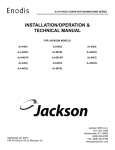
SERVICE INSTRUCTIONS
MONTAGE-INSTRUCTIES
EINBAUANLEITUNG
INSTRUCTIONS DE MONTAGE
INSTRUCCIONES DE SERVICIO
取扱い説明書
ISTRUZIONI per l'ASSISTENZA
MANUAL DE INSTRUÇÕES
Cycle Computer
SC-6500/SC-6500-M
SC-6500-MX /SC-6500-T
English
3 – 24
Dutch
25 – 46
German
47 – 68
French
69 – 90
Spanish
91 – 112
Japanese
113 – 134
Italian
135 – 156
Portuguese
157 – 178
English
Cycle Computer
SC-6500 /SC-6500-M
SC-6500-MX /SC-6500-T
INDEX
1. External appearance
・ ・ ・ ・ ・ ・ ・ ・ ・ ・ ・
5
・ ・ ・ ・ ・ ・ ・ ・ ・ ・ ・ ・ ・ ・
6
・ ・ ・ ・ ・ ・ ・ ・ ・ ・ ・ ・ ・ ・ ・
8
2. Display Contents
3. Display Modes
• Current speed (VEL) ・ ・ ・ ・ ・ ・ ・ ・ ・ ・ ・ ・
• Gear indicator (bar) • Time display (CLK)
・ ・ ・
9
• Trip distance group (TIM, DST, MAX, AVE)
・ ・ ・
10
・ ・ ・ ・ ・ ・ ・ ・ ・ ・ ・ ・ ・
11
• ODO meter (ODO) ・ ・
• Stopwatch (STW) group
• Cadence (rpm) ・ ・ ・ ・ ・ ・ ・ ・ ・ ・ ・ ・ ・ ・ ・ ・ ・ ・ 12
• Main display cadence (VEL) • Lap counter (CNT)
・ ・ ・ ・ ・ ・ ・ ・ ・ ・
13
・ ・ ・ ・ ・ ・ ・ ・ ・ ・ ・ ・ ・ ・
14
・ ・ ・ ・ ・ ・ ・ ・ ・ ・ ・ ・ ・ ・ ・ ・ ・ ・ ・ ・
14
• Digital gear number F - R ・ ・
• Gear ratio • Pace Arrow
• Low battery display (LO BAT)
• Power saver function
4. Resetting
5. Viewing data after removing the
computer from the bracket mount
6. Setting tolerances
・ ・ ・ ・ ・ ・
15
・ ・ ・ ・ ・ ・ ・
16
・ ・ ・ ・ ・ ・ ・ ・ ・ ・ ・ ・ ・ ・ ・ ・ ・ ・ ・
17
7. Installation to the bicycle
8. Data input
Trouble Shooting
・ ・ ・ ・ ・ ・ ・ ・ ・ ・ ・ ・ ・ ・ ・
24
3
Warning
Be careful not to pay excessive attention to
the computer data while riding, otherwise you
might have an accident.
Specifications
Model No.
STI lever
SC-6500 SC-6500-MX SC-6500-T
SC-6500-M
ST-M951
ST-M950
SL-M951
ST-M952 SL-M952
ST-M750 SL-M750
SL-M570 SL-M570
ST-6501
ST-5500-C
ST-T400
ST-T300
NOTE;
* The all clear (AC) button is used to clear the main unit memory.
* Never disassemble the main unit, as it cannot be reassembled.
* The main unit is fully waterproofed to withstand wet weather
conditions; however, do not deliberately place it into water.
* Avoid leaving the main unit exposed to extremely hot weather
conditions.
* Handle the main unit carefully, and avoid subjecting it to any
shocks.
* Do not use thinner or other solvents to clean parts such as the
main unit and sensor, as they may dissolve the part casings.
* To clean these parts, wipe them with a cloth soaked in a weak
mixture of neutral detergent and water.
4
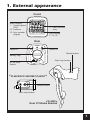
1. External appearance
Front
Main Display
1. Current speed
(VEL)
10. Cadence
15. Gear number
(digital)
17. Gear indicator
(bar)
Sub Display
2 - 14, 16
Rear
Switch B
Switch A
Mode button
Battery cap
Start stop button
AC All clear
Switch
< SC-6500-M /SC-6500-MX /SC-6500-T >
Mode button
Start stop button
< SC-6500 >
Rear STI Brake Bracket
5
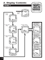
2. Display Contents
mode 1
2. Clock
(CLK)
3. Trip time
(TIM)
4. Trip distance
(DST)
5. ODO meter
(ODO)
6
1. Current
speed
(VEL)
6. Stop watch
7. Stop watch–
trip distance
(DST STW)
8. Stop watch–
average speed
(AVE STW)
9. Stop watch–
maximum speed
(MAX STW)
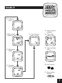
mode 2
10. Cadence
(rpm)
15. Gear number
(digital)
11. Main display
cadence
12. Maximum
speed
13. Average
speed
14. Lap counter
16. Gear ratio
17. Gear indicator
(bar)
18. Pace Arrow
19. Low battery
display
7
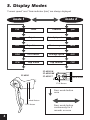
3. Display Modes
“Current speed” and “Gear indicator (bar)” are always displayed
mode 1
mode 2
CLK
Clock
Cadence
rpm
TIM
Trip time
Main display cadence
VEL
DST
Trip distance
Maximum speed
MAX
ODO
ODO meter
Average speed
AVE
STW
Stop watch
Lap counter
CNT
SC-6500
SC-6500-M
SC-6500-MX
SC-6500-T
Mode Button
ST/SP Button
Press mode button
once
Mode Button
ST/SP Button
8
Press mode button
continuously for 2
seconds or more
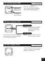
(1) Current speed (VEL)
When main
display cadence
appears on top
km/h, mph
0.0 (2.0) - 130.0km/h
0.0 (1.2) - 80.0mph (Range)
The current speed will appear at
the top of the main display.
Current speed
will appear in
the sub - display
(2) Gear indicator (bar)
Front display
Displays; Low position for double
front chainwheel Mid
position for triple front
chainwheel
Rear display
Gear indicator bar will not appear
if the sensor wire is not connected
or it has been turned off.
(3) Time display (CLK)
Displays; Top for smallest sprocket
Low for largest sprocket
24 - hours clock
Clock will appear when changing
mode 2 to mode 1 and during
power saver function.
9
(4) Trip distance group (TIM, DST, MAX, AVE)
The trip distance group includes trip time (TIM) , trip distance (DST)
maximum speed during trip (MAX) average speed during trip (AVE).
To activate the trip distance group, press the Mode button until “TIM” is
displayed, and then press the ST/SP button.
The km/mile symbol will blink. The computer will automatically record
data whenever the wheel sensor is activated by wheel rotation. The
computer will automatically stop recording data when the wheel stops
rotating.
To manually stop functions, press the ST/SP button once.
To reset trip distance group, press the Mode button and ST/SP button
simultaneously.
Whole group will reset to zero.
Additionally, while this group is operating the km/mph, rpm and F - R
displays will flash.
Trip time (TIM)
Trip distance (DST)
Maximum speed (MAX)
0 - 99:59:59 (h ; min ; sec)
0 - 999.99 (km, mile)
0.0 (2.0) - 130.0km/h
Average speed (AVE)
0.0 (2.0) - 130.0km/h
0.0 (1.2) - 80mph.
Note;
To calculate the average speed,
You must travel for more than 10
seconds or more.
An arrow - up displayed indicates
that your current speed is faster
than your average speed and an
arrow - down if the speed is lower.
If the trip time (TIM) exceeds 100 hours or the trip distance (DST) exceeds
1,000 kilometers (1,000 miles), the values for the trip time (TIM) and the
trip distance (DST) will return to zero and measurement will then continue.
However, "ER" will be displayed as the average speed (AVE). To clear this
display, reset it to zero. Note that this will clear all of the values for the
measurements made up until that point.
10
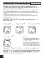
(5) ODO meter (ODO)
0 - 9999.9 km, mile
(6) Stopwatch (STW) group
STW
DST, STW
AVE, STW
MAX, STW
This group includes stopwatch trip distance average
speed and maximum speed.
The stopwatch is activated by pressing ST/SP button.
While the stopwatch group is operating the stopwatch
(STW) display will flash.
Stopwatch trip distance (DST,STW) records total during
STW function.
Stopwatch average speed (AVE,STW) records the
average speed during STW function.
Maximum speed (MAX,STW) records the Maximum
speed during the stopwatch function.
Stopwatch (STW)
Stopwatch-Trip distance (DST, STW)
Stopwatch-Average speed (AVE, STW)
Stopwatch-Maximum speed (MAX, STW)
Press switch B to change mode
Note;
The functions of this group are
only available when stopwatch is
activated.
If the trip distance mode is also
activated simultaneously, it is not
possible to view at the distance.
However the trip distance,
average speed and maximum
speed will still be recorded during
this time.
Stopwatch
(STW)
Stopwatch trip
distance (DST,STW)
Stopwatch average
speed (AVE,STW)
Stopwatch maximum
speed (MAX, STW)
0.0 - 90:00 (min,sec)
km mile
km/h mile/h
km/h mile/h
11
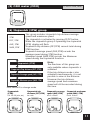
(7) Cadence (rpm)
Cadence is calculated from the F - R
gear tooth numbers and current
speed.
Note;
Cadence always appears during
bicycle movement regardless if the
crankarms are rotating.
(8) Main display cadence (VEL)
Cadence (rpm) can also be shown
in main display. Current speed
will move to sub - display.
Cadence on main display
Current speed on sub - display
(9) Lap counter (CNT)
This function is used to count laps,
etc. (range 0 - 99)
Lap counter is activated by
pressing the ST/SP button.
To reset the counter to zero, press
mode and ST/SP button
simultaneously.
To reset all of the TIM group, STW
group and lap counter values to
zero, press the Mode button and
ST/SP button simultaneously for 2
seconds or more.
This is possible regardless of what
is currently appearing on the
display.
12
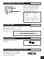
(10) Digital gear number F - R
Gear combinations are displayed
when a shift has been made. This
will show for approx 4 seconds
then original screen will return.
R
Gear ratio
The gear combinations are;
• Front double
inner ・ ・ ・ 1
outer ・ ・ ・ 2
F
• Front triple
inner ・ ・ ・ 1
mid ・ ・ ・ ・ ・ 2
outer ・ ・ ・ 3
Rear Numbers are displayed in
order starting from low end.
Low1 ・ ・ ・ ・ ・ High ・ ・ ・ ・ ・ 9.etc.
(11) Gear ratio
Gear ratio is also displayed only when a
shift has been made.
This will show for approx 4 seconds.
Gear ratio formula;
Gear ratio =
number of teeth front chain wheel 48
= 3.2
number of teeth rear sprocket
15
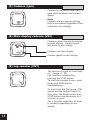
(12) Pace Arrow
Moves when distance time is
operating
(13) Low battery display (LO BAT)
This flashes when the remaining
battery power is low. The battery
should be replaced with a new
one as soon as possible.
13
(14) Power saver function
When the computer is left without
receiving any signal or any button
activation the unit will be in a
“sleep” state and only the clock will
appear on the display.
The normal display will return as
soon as a signal is received or a
button has been pressed.
Note;
During the stopwatch function the
stopwatch will continue to operate
even when the power saver
function has been activated. The
stopwatch will stop automatically
after 90minutes have passed.
4. Resetting
This function allows you to reset km/h - mph, tire circumference, gear
combination, type of rear derailleur, and time without losing any data (i.e.
total distance, trip distance etc)
To re - set go to any display other than CLK on the sub display. Press switch
“B” for 5 seconds or more. Then follow instruction section 8 data input.
Switch B 5sec.
km/h mile/h
Tire circumference
F - R no.of chainring teeth, no.of sprocket teeth
Type of rear derailleur
Time
Sub - display (CLK)
Switch B 5sec.
Normal display
14
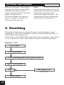
5. Viewing data after removing the
computer from the bracket mount
The data can still be viewed even when the computer has been removed
from the handlebar bracket.
mode1
mode2
CLK
rpm
STW
TIM
VEL
DST, STW
DST
MAX
AVE, STW
ODO
AVE
MAX, STW
STW
CNT
changes in order when switch A is pressed
changes in order
when switch B is
pressed
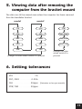
6. Setting tolerances
VEL
・ ・ ・ ・ ・ ・ ・ ・ ・ ・ ・ ・ ・ ・ ・ ・ ・ ・ ・ ・ ・
DST, ODO
CLK
・ ・ ・ ・ ・ ・ ・ ・ ・ ・ ・
・ ・ ・ ・ ・ ・ ・ ・ ・ ・ ・ ・ ・ ・ ・ ・ ・
STW, TIM
・ ・ ・ ・ ・ ・ ・ ・ ・ ・ ・ ・
1%
0.05%
30ppm (5minutes or less per month)
50ppm
15
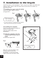
7. Installation to the bicycle
Install the levers to the handlebars. Then connect and adjust the brake and
shifting cables. Refer to the STI Lever Service Instructions for details on
these procedures.
(1) Installing the signal cable (SC-6500)
Install the signal cable as shown
in Figure No1.
Fig.1
Tightening torque:
0.3 - 0.5 Nm
{ 2 - 4 in. lbs. }
* For the SC-6500-M, SC-6500-MX and SC-6500-T,
refer to the Service Instructions included.
(2) Installing the computer
Install the band and the bracket as
shown in Figure No2.
Tape the signal cable to the
handlebars.
Fig.2
Bracket
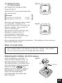
(3) Slide the computer onto the
bracket until it clicks into its
place.
as shown in Figure No3.
Fig.3
Band
Bracket
Computer
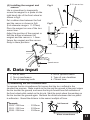
After this, wrap handlebar with
finishing tape around the
handlebars to secure both the
signal cable and the brake cable
16
Tightening torque:
1 Nm
{ 8 in. lbs. }
(4) Installing the magnet and
sensors
Use a screwdriver to temporarily
secure the magnet to a spoke on the
right hand side of the front wheel as
shown in fig4.
Put a rubber shim between the fork
and the sensor as shown in fig5.
(Fork diameter range is 11 - 35mm)
Place the magnet on one of the two
sensor lines.
Adjust the position of the magnet so
that the distance between the
magnet and the sensors is 1- 5mm.
Secure the magnet and the sensors
firmly in these positions.
Ø 2.1mm or less
Fig.4
Fig.5
Sensors
Sensors
Pull
Front Fork
Front Fork
Magnet
1 - 5 mm
Plastic tie
Speed sensor
8. Data input
4. No.of sprocket teeth
5. Type of rear derailleur
6. Current time
1. Km or Miles
2. Tire circumference
3. No.of chainring teeth
(1) Measuring the tire circumference
To measure the tire circumference,first ensure that the tire is inflated to the
standard tire pressure. Make a mark on the tire and the ground at the point where
the tire touches the ground, and move the bicycle forward one full revolution of
the front wheel while seated on the bicycle, Mark the point where the marking on
the tire touches the ground again. Measure the distance between the two points
in millimeters. Round the distance to the nearest multiple of 5mm.
[
Example
2028 - 2032mm ・
2033 - 2037mm ・
2038 - 2042mm ・
・ ・ ・ ・
・ ・ ・ ・
・ ・ ・ ・
2030mm
2035mm
2040mm
]
Roll forward
Wheel circumference
17
(2) Checking the number of chainring and sprocket teeth
Check whether the front chainwheel is a double or a triple chainwheel.
Example
Check whether the
cassette has 7,8, or 9
sprockets.
48x38x28
[
・ ・ ・
triple
53x39
・ ・ ・ ・
Example
12,13,14,15,16,17,19,21,23
12,13,14,15,16,17,19,21 ・ ・
(3) Selecting Km or Miles
When switch “AC” (All Clear) is
pressed, the display as shown in
fig6 appears and the k/h setting
starts flashing. Select your choice
for Km/h or Mile/h by pressing
switch “A”.
Once your choice is displayed,
press switch “B” continuously for 2
seconds or more to set.
Double
・ ・ ・ ・ ・
・ ・ ・ ・ ・
9 sprocket
8 sprocket
Fig.6
(4) Entering the tire circumference
The display will appear as shown in fig7, Enter the value which was
measured previously.
Fig.7
2050 • • • Tire circumference (mm)
26 1.75 • • • Indicates the tire size
for 26inch x 1.75
18
]
The value will increase by 5mm each time switch “A” is pressed.
The value will change rapidly when switch “A” is pressed continuously.
Once the desired value is displayed, press switch “B” for 2 seconds or more
to set.
In the case of tires which have circumference of less than 2050mm, press
switch “A” continuously. After the value increases to 2395, it will change
to 1700.
Continue pressing switch “A” until the desired value is reached, and then
press switch “B” 2 seconds or more to set.
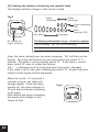
The tire size display can appear as any one of the following 11 displays, in
addition to 26 x 1.75 (2050mm)
Tires with sizes other that these are
not displayed
700 18
・ ・ ・ ・ ・ ・ ・ ・
700 x 18C (2070)
700 19
・ ・ ・ ・ ・ ・ ・ ・
700 x 19C (2090)
700 20
・ ・ ・ ・ ・ ・ ・ ・
700 x 20C (2110)
700 25
・ ・ ・ ・ ・ ・ ・ ・
700 x 25C (2115)
700 28
・ ・ ・ ・ ・ ・ ・ ・
700 x 28C (2135)
26
13/8
・ ・ ・ ・ ・ ・
26inch x 1 3/8(2075)
・ ・ ・ ・ ・ ・ ・
26inch x 2.00 (2085)
26
2.00
26
11/2
26
1.00
26
1.4
・ ・ ・ ・ ・ ・ ・ ・
26inch x 1.40 (2005)
26
1.5
・ ・ ・ ・ ・ ・ ・ ・
26inch x 1.50 (2050)
・ ・ ・ ・ ・ ・
・ ・ ・ ・ ・ ・ ・
26inch x 1 1/2 (2100)
26inch x 1 (1970)
19
(5) Entering the number of chainring and sprocket teeth
The display will then change to that shown in fig8.
Fig.8
Inner
chainring
Outer
chainring
Front chainring
(3S)
Rear
sprocket (9S)
Low gear
No. of teeth for
largest chainring
Top gear
The following tooth numbers are pre - set into the computer
Front chainrings 48 x 38 x 28 (3 chainrings)
Cassette
12,13,14,15,16,17,19,21,23 (9 sprockets)
Enter the value starting from the outer chainring. “48” will flash on the
display. The value will increase by one tooth each time switch “A” is
pressed. The value is set by pressing switch “B”. If the value is correct,
press switch “B” once to accept the setting.
The “- -” is displayed once for every five times the value is changed.
If this value is set for the outer chainring by switch “B”, all gear indicator
related screen display will be eliminated.
When the switch “A” is pressed 2
seconds or more, the value will
change rapidly. Once the value
reaches 60, the value changes to
40 and then continues increasing
to 60 again.
After setting the largest chainring
the display will change to that
shown in fig9.
20
Fig.9
Enter the number of teeth for the
inner chainring (for double front
chainwheel) or the middle
chainring (for triple front
chainwheel).
“38” will flash on the display. This
position can be set from 20 - 50 by
the same procedure of setting
outer chainring. After setting the
inner chainring or the middle
chainring, the display will change
to that shown in fig10.
Fig.10
When using a double front chainwheel, press switch “A” once so that “- -”
is displayed, and then press switch “B” once to set, the front chainwheel
will then be registered as a double front chainwheel and the display will
change to show the rear sprocket settings.
When using a triple front chainwheel, the value can be set from 15 to 34
by the same procedure of setting middle chainring.
Entering the number of rear
sprocket teeth
Fig.11
The display will then change to
that shown in fig11.
Enter the number of teeth for each
sprocket by the same procedure as
that used for the chainrings.
Press switch “A” to set the desired
number of teeth, and then press
switch “B” to accept the setting.
The value can be set from 11 to
42. Once the setting for smallest
sprocket through to the 7th
sprocket have been made, the
display will change to that shown
in fig12.
Fig.12
No. of 7th sprocket
plus one teeth
No. of 7th sprocket
21
If the cassette has seven sprockets, press switch “A” once to change the
flashing “21” to “- -”, and then press switch B once. This will indicate that
there is no 8th sprocket, and the operation for entering the number of
sprocket teeth will be complete.
If the cassette has 8 sprockets, enter the number of teeth for this position
and follow the same procedure as above to enter “- -” in the 9th position
otherwise enter the number of teeth for the 9th sprocket.
Checking the number of teeth entered
Once the setting of number of sprocket teeth is completed, the display will
return to the initial input display. Re check all values by repeatedly
pressing switch “B” to
confirm each number of teeth. Press switch “B” once each time and check
whether the entered number of teeth are matching with the sprocket
position on the display.
If all values entered are
correct, press switch “B” for
Indicated
2 seconds or more to
Section
continue the next entry
procedure.
This Value
(6) Entering the type of rear derailleur
The display will change to that shown in fig 13. The display will change
from “111” to “222” each time switch “A” is pressed.
111
・ ・ ・ ・ ・
for Traditional rear
derailleur
222
・ ・ ・ ・ ・
for Rapid Rise Rear
derailleur (reverse
spring type)
Press switch “B” for 2 seconds or
more to continue the next entry
procedure.
22
Fig.13
(7) Setting the time
(24 hour format)
The display will change to that
shown in fig 14.
Fig.14
Set the time to one minute later than
the current time.
[
Example
If the time is 10:46:23
If the time is 13:59:16
・ ・ ・ ・
・ ・ ・ ・
10:47: - 14:00: - -
The hours will advance when switch
“A” is pressed. If switch “A” is
pressed continuously, the hours will
advance rapidly. Press switch “B”
once to set the hour.
The minutes section will then start
flashing as shown in Fig 15.
Set the minutes in the same
procedure as for setting the hours.
The clock will then start.
]
Fig.15
This completes the data entry operations. The display will now return to
the normal display mode.
Note; To reset clock
Get a display where CLK appears on the sub - display. Press switch
“B” for 5 seconds or more to change the time setting.
Replacing the battery (CR-2032 battery)
Insert the battery so that the “+”
side is visible as shown in Fig. 16,
and then tighten the battery cap.
The battery which is installed at the
time of purchase is for monitoring
purposes. If the
low
battery indicator appears, replace
the battery as soon as possible.
Carry out the initialization
procedure after the battery has
been replaced.
Fig.16
Close
Open
CR-2032
23
@@@@@@@@e?
@@@@@@@@e?@@@@@@@@?e@@@@@@@@e?@@@@@@@@?e@@@@@@@@e?@@@@@@@@?e@@@@@@@@e?@@@@@@@@?e@@@@@@@@e?@@@@@@@@?e@@@@@@@@e?@@@@@@@@?e@@@@@@@@e?@@@@@@@@?e
@@@@@@@@e?
@@@@@@@@e?@@@@@@@@?e@@@@@@@@e?@@@@@@@@?e@@@@@@@@e?@@@@@@@@?e@@@@@@@@e?@@@@@@@@?e@@@@@@@@e?@@@@@@@@?e@@@@@@@@e?@@@@@@@@?e@@@@@@@@e?@@@@@@@@?e@@@@@@@@
@@@@@@@@
@@h?
@@
@@h?
@@
@@h?
@@
@@h?
@@
@@h?
@@
@@h?
@@
@@
@@
@@
@@
@@
@@
@@
@@
@@
@@
@@
@@
@@
@@
@@
@@
@@
@@
@@
@@
@@
@@
@@
@@
@@
@@
@@
@@
@@
@@
@@
@@
@@
@@
@@
@@
@@
@@
@@
@@
@@
@@
@@
@@
@@
@@
@@
@@
@@
@@
@@
@@
@@
@@
@@
@@
@@
@@
@@
@@
@@
@@
@@
@@
@@
@@
@@
@@
@@
@@
@@
@@
@@
@@
@@
@@
@@
@@
@@
@@
@@
@@
@@
@@
@@
@@
@@
@@
@@
@@
@@
@@
@@
@@
@@
@@
@@
@@
@@
@@
@@
@@
@@
@@
@@
@@
@@
@@
@@
@@
@@
@@
@@
@@
@@
@@
@@
@@
@@
@@
@@
@@
@@
@@
@@
@@
@@
@@
@@
@@
@@
@@
@@
@@
@@
@@
@@
@@
@@
@@
@@
@@
@@
@@
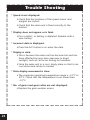
Trouble Shooting
* Speed is not displayed.
• Check that the positions of the speed sensor and
magnet are correct.
• Check that the main unit is fixed correctly to the
bracket.
* Display does not appear or is faint.
• Poor contact, or battery is depleted. Replace with a
new battery.
* Incorrect data is displayed.
• Press the A/C button to re - enter the data.
* Display is dark.
• This is because the main unit has become hot and has
been affected by long - term exposure to direct
sunlight, such as can occur during hot weather.
• Store the main unit in a cool, shady place so that it can
cool down and return to normal.
* Data display movement is slow.
• The computer operating temperature range is –10°C to
50°C. Check that the temperature is not lower than
–10°C.
* No. of gears and gear ratios are not displayed.
• Replace the gear number sensor.
@@
@@
@@
@@
@@
@@
@@
@@
@@
@@
@@
@@
@@
@@
@@
@@
@@
@@
@@
@@
@@
@@
@@
@@
@@
@@
@@
@@
@@
@@
@@
@@
@@
@@
@@
@@
@@
@@
@@
@@
@@
@@
@@
@@
@@
@@
@@
@@
@@
@@
@@
@@
@@
@@
@@
@@
@@
@@
@@
@@
@@
@@
@@
@@
@@
@@
@@
@@
@@
@@
@@
@@
@@
@@
@@
@@
@@
@@
@@
@@
@@
@@
@@
@@
@@
@@
@@
@@
@@
@@
@@
@@
@@
@@
@@
@@
@@
@@
@@
@@
@@
@@
@@
@@
@@
@@
@@
@@
@@
@@
@@
@@
@@
@@
@@
@@
@@
@@
@@
@@
@@
@@
@@
@@
@@
@@
@@
@@
@@
@@
@@
@@
@@
@@
@@
@@
@@
@@
@@
@@
@@
@@
@@
@@
@@
@@
@@
@@
@@
@@
@@
@@
@@
@@
@@
@@
@@
@@
@@
@@
@@
@@
@@
@@
@@
@@
@@
@@
@@g
@@g
@@g
@@g
@@g
@@g
@@@@@@@@
@@@@@@@@ ?@@@@@@@@?e@@@@@@@@e?@@@@@@@@?e@@@@@@@@e?@@@@@@@@?e@@@@@@@@e?@@@@@@@@?e@@@@@@@@e?@@@@@@@@?e@@@@@@@@e?@@@@@@@@?e@@@@@@@@e?@@@@@@@@?e@@@@@@@@
?@@@@@@@@?e@@@@@@@@e?@@@@@@@@?e@@@@@@@@e?@@@@@@@@?e@@@@@@@@e?@@@@@@@@?e@@@@@@@@e?@@@@@@@@?e@@@@@@@@e?@@@@@@@@?e@@@@@@@@e?@@@@@@@@?e@@@@@@@@
24
@@
@@
@@
@@
@@
@@
@@
@@
?@@
?@@
?@@
?@@
?@@
?@@
?@@@@@@@@
?@@@@@@@@