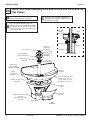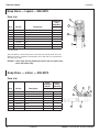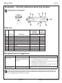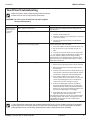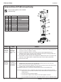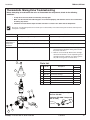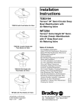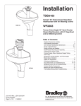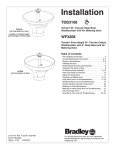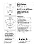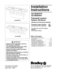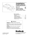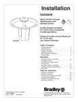
1
Installation TDB3104 Terreon 54" Semi-Circular Deep Bowl Washfountain with TouchTime ® ® TDB3104 with TouchTime Control Available in standard height (shown here), juvenile height, and TAS height. WF3204 Terreon Extra Height 54" Semi-Circular Classic Washfountain with 9" Deep Bowl and TouchTime ® Table of Contents Pre-Installation Information...............................................2 Semi-Circular Washfountain Dimensions......................3-4 Rough-In Specifications................................................ 5-6 Installing the Drain............................................................7 Bowl/Pedestal Mounting and Assembly...........................8 Installing Drain Spud in Bowl............................................8 Connect Supply Tubing to Sprayhead..............................9 TouchTime Valve Assembly......................................10-13 Valve and Tubing Connections.......................................14 Valve and Electrical Connections...................................15 Adjust the Temperature..................................................15 Cleaning and Maintenance.......................................16–17 Soap Valve Parts List and Maintenance...................18–19 Sprayhead Parts List and Troubleshooting.....................20 TouchTime Troubleshooting............................................21 Solenoid Valve Troubleshooting......................................22 Thermostatic Mixing Valve Troubleshooting...................23 ® WF3204 with TouchTime Control 215-1578 Rev. D; ECN 12-00-004 © 2013 Bradley Page 1 of 23 1/15/2013 P.O. Box 309, Menomonee Falls, WI USA 53052-0309 PHONE 800.BRADLEY (800.272.3539) FAX 262.251.5817 bradleycorp.com TDB3104, WF3204 Installation IMPORTANT! Read this entire installation manual to ensure proper installation. When finished with the installation, file this manual with the owner or maintenance department. Installation Packing List IS TH SIDE UP • • • • Separate parts from packaging and make sure all parts are accounted for before discarding any packaging material. If any parts are missing, do not begin installation until you obtain the missing parts. Make sure that all water supply lines have been flushed and then completely turned off before beginning installation. Debris in supply lines can cause valves to malfunction. Hardware supplied by installer must be appropriate for wall construction. Wall anchors used must have a minimum pull-out rating of 1,000 lbs. Product warranties may be found under “Product Information” on our web site at www.bradleycorp.com. Supplies Required by Installer • (4) 1/2" lag bolts, screws or other fasteners to anchor washfountain pedestal • 1/2" nominal copper tubing for hot and cold water supply lines. • Standard P-trap (vented trap supplied by Bradley when required) • 2" drain lines and fittings • 1-1/2" vent or tie pipe on fixtures vented through washfountain column • Teflon tape or pipe dope • 110 VAC GFI power source for 110/24 VAC UL Class II transformer supplied • OPTIONAL: Bradley recommends installing an electrical cutoff switch to the unit. This feature allows no accidental water delivery during regular maintenance and service. Pre-Installation Information Terreon Material ® The Washfountain is constructed of Terreon , a densified solid surface material composed of polyester resin. Terreon is resistant to chemicals, stains, burns and impact. Surface damage can be easily repaired with everyday cleaners or fine-grit abrasives. Terreon is NAHB certified to meet ANSI Z124.3, Z124.6 and ANSI/ICPA SS-1-2001. ® TouchTime Control Each Touchtime pushbutton activates a flow of water. Each nozzle is controlled by a separate solenoid valve, allowing each user to activate a flow of tempered water from one spray nozzle with a pushbutton for 15 seconds. Each valve uses less than half the maximum amount of hot water allowed by the ANSI/ASHRAE/IES 90A-1980 Standard. Solenoid Valve An electronically controlled solenoid valve serves as the metering mechanism. Few moving parts provide reliable metering performance and the solenoid is unaffected by chemicals and minerals often present in municipal water supplies. 2 1/15/2013Bradley • 215-1578 Rev. D; ECN 12-00-004 TDB3104, WF3204 Installation Semi-Circular Washfountain Dimensions Model TDB3104 Model TDB3104 (Juvenile Height) 54" Semi-circular - side view 54" Semi-circular - side view 32-1/4" (819) 32-1/4" (819) 5-1/4" (133) 5-1/4" (133) Adjust to Towel Dispenser Mounting Holes Adjust to Towel Dispenser Mounting Holes 6" (152) 6" (152) 64" (1626) w/ soap 55-1/2" (1410) w/o soap 55-3/4" (1416) 47-1/4" (1200) 43-3/4" (1111) 34"* 27" 34" (864) (686) (864) 22-3/4" (577) 40" (1016) 59-1/2"* (1511) w/ soap 51"* (1295) w/o soap 51-1/4"* (1301) 22-3/4" (577) 42-5/8"* (1084) 39-1/8"* (994) 30"* (762) 23-1/2" (597) 23-1/2"* (597) 15" (381) 15" (381) Model TDB3104 is ADA Compliant * Add 2" (51) for TAS height unit Optional equipment may not comply with all ADA dimensional guidelines Model TDB3104 54" Semi-circular - rear view pedestal access Check local codes for electrical outlet location before roughing in. Some codes require a remote location for the outlet. 12-1/2" (318) 3-1/2"* (89) 8"* (203) 17-1/2" (444) Bradley • 215-1578 Rev. D; ECN 12-00-004 1" (25) 1/15/2013 3 TDB3104, WF3204 Installation Semi-Circular Washfountain Dimensions Model WF3204 54" Semi-circular - side view 32-1/4" (819) 22-3/4" (577) 5-1/4" (133) Adjust to Towel Dispenser Mounting Holes 6" (152) 64" (1626) w/ soap 55-1/2" (1410) w/o soap 55-3/4" (1416) 47-1/4" (1200) 43-3/4" (1111) 41" (1041) 23-1/2" (597) 34" (864) 15" (381) Model WF3204 is not ADA compliant 4 1/15/2013Bradley • 215-1578 Rev. D; ECN 12-00-004 TDB3104, WF3204 Installation (mm) Rough-In Specifications 1/2" Nominal Copper Tubing for Cold Supply Through Floor (optional), Stub Up 2-1/2" (64) Above Floor 1/2" nominal copper tubing supplies through wall - Supplies from below or through wall - Vent from below or through wall off-drain 2" NPT Drain Through Floor, Stub up 3" (76) Above Floor 13" R Top Access 7-5/8" (194) 7-5/8" (194) 4" (102) 54" (1372) Bowl Wall Type A Drain 5-1/4" (133) 7-3/8" R Bottom Access 3-1/4" (83) 1/2" Nominal Copper Tubing for Hot Supply Through Floor (optional), Stub Up 2-1/2" (64) Above Floor Trap for Wall Outlet Only 4" (102) Clearance Hole 6" to 13-1/4" (152 to 337) Drain Through Wall Supplies Through Wall 12" (305) Drain and Supplies Through Floor Trap Located Below Floor (Optional) (mm) Type B Drain - Supplies from above - Vent through ceiling off trap inside pedestal 1-1/2" NPT Vent to Ceiling 1-1/4" (32) 13" R Top Access 7/8" Cold (22) Hot 4" (102) 7/8" (22) 1/2" Nominal Copper Tubing Supply from Above 54" (1372) Bowl Wall 7-3/8" R Bottom Access 5-1/4" (133) 2" NPT Drain, Stub Out 3" (76) Above Floor Wall Vent Drain Through Floor Bradley • 215-1578 Rev. D; ECN 12-00-004 1/15/2013 5 TDB3104, WF3204 Installation Rough-In Specifications Type H Drain - Supplies from below or through wall - Vented through ceiling off trap inside pedestal (mm) 1/2" Nominal Copper Tubing Supplies Through Wall 13" R Top Access 7-3/8" R Bottom Access 7-5/8" Cold (194) 1-1/2" NPT Vent to Ceiling 1/2" Nominal Copper Tubing Supplies Through Floor (optional), Stub Up 2-1/2" (64) Above Floor 4" (102) 7-5/8" Hot (194) Wall 54" (1372) Bowl 5-1/4" (133) 2" NPT Drain, Stub Up 3" (76) Above Floor 3-1/4" (83) Wall Vent 12" (305) Drain Through Floor Supplies Through Floor (Optional) (mm) Type O Drain 13" R Top Access - Supplies from above Trap - Vented from below or through wall off drain 7/8" (22) 2" NPT Drain Through Wall (Stub Out to Suit Trap Dimension) 2" NPT Drain Through Floor, Stub Up 3" (76) Above Floor Cold Hot 7/8" (22) 4" (102) 54" (1372) Bowl 1-1/4" (32) 1/2" Nominal Copper Tubing Supplies From Above 7-3/8" R Bottom Access 5-1/4" (133) Trap For Wall Outlet Only 6" to 13-1/4" (152 to 337) Wall 4" (102) Clearance Hole Drain Through Wall Drain Through Floor Trap Located Below Floor (Optional) 6 1/15/2013Bradley • 215-1578 Rev. D; ECN 12-00-004 TDB3104, WF3204 Installation 1 Installing the Drain A Rough in supply and drain piping as required for your installation. B Assemble the drain to the dimension for the bowl you are installing. All piping shown in dotted lines to be supplied by installer. Types B, H Vent or Tie Pipe (Supplied by Installer) 2" NPT Coupling if Tie Pipe is Not Required (Supplied by Installer) Vented Trap (111-024) B - See Table 1 Centerline of Washfountain Centerline of Washfountain 4" (102) B - See Table 1 Vent or Tie Pipe (Supplied by Installer) 4" (102) Optional Tie Pipe Bracket (S70-082) Types A, O B - See Table 1 Centerline of Washfountain See Rough-In information for dimensions not shown. 4" (102) Types A, O with Tie Pipe Bracket Option Table 1 — “B” Trap Dimensions Dim Standard Height Juvenile Height TAS B 23-3/8" (594mm) 22-1/2" (572mm) 24-1/2" (622mm) Bradley • 215-1578 Rev. D; ECN 12-00-004 1/15/2013 7 TDB3104, WF3204 2 A Installation Bowl/Pedestal Mounting and Assembly Position the pedestal at desired location and mark the position of the (2) pedestal wall mounting locations and (2) pedestal floor mounting locations. CAUTION! Bowl surface is very smooth. Approximate weight of bowl is 146 pounds (model TDB3104), 136 pounds (model WF3204) or 101 pounds (model TDB3104/JUV). Handle with Care! Top View TAS OPTION: Place TAS spacer on floor over the mounting holes. Place pedestal on top of the spacer. B Secure pedestal to wall and floor with suitable fasteners, 1/2" anchors and bolts (supplied by installer). Drain Front View C Using two to three people, carefully lift bowl onto pedestal. D Position the bowl so that the threaded rods in the bowl mate with the slotted holes in the pedestal. E 3 A Using 1/4" wing nuts and washers, secure the bowl to the pedestal, three places. Wall Mounting Locations Installing Drain Spud in Bowl Loosely attach the drain spud to the bowl with the locknut and washer. B TRAP OPTION: attach B trap to drain spud. Place Hands Here When Lifting Bowl Place Hands Here When Lifting Bowl Threaded Rod (Secured by 1/4" wing nut and washer) Pedestal Floor Mounting Locations Seal between drain spud and drain hole with plumber’s putty (supplied by installer). Drain Pre-Pack (S45-273) Strainer (S45-067) Spud (112-015) Tie Pipe OPTION: attach tie pipe bracket to drain spud. 8 B Tighten the spud and lock nut against the bowl. C Secure the strainer to drain spud with the screws provided. D Connect spud (or B Trap or Tie Pipe Bracket) to drain. Bowl Washer (142-068) Locknut (161-021) 1/15/2013Bradley • 215-1578 Rev. D; ECN 12-00-004 TDB3104, WF3204 Installation 4 Connect Supply Tubing to Sprayhead Install 3/8" supply tubing in the sprayhead using the male tube connector. Male Tube Connector • Using a sharp razor, cut tubing squarely and remove any burrs. DO NOT pinch or crush end of tubing. A • Loosen nut on fitting. Moisten end of tube and push into fitting until it is firmly seated. Tighten nut to secure tube to fitting (make sure nut is securely tightened). Nut Tubing Sprayhead • If connector leaks, reseat tubing. If leaking persists, replace male connector, or call your Bradley representative for assistance. Tubing Bradley • 215-1578 Rev. D; ECN 12-00-004 1/15/2013 9 TDB3104, WF3204 5a Installation TouchTime Valve Assembly for A Drain and O Drain Units without Tie Pipe Option A Install hemmed end (not sharp end) of support tube with gasket onto bowl. B Place sprayhead with 3/8" tubing onto support tube. Run the tubing down through the support tube and connect to valve tube connector. Make sure the spray holes point away from the wall. C Place the upper tie bar (notched at both corners of each end) on top of sprayhead parallel to wall. Connect the longer tie rod to the 4-1/4" tie rod using the coupling nut with hex head set screws. Run the tie rod assembly down through upper tie bar and secure from underneath the bowl using lower tie bar (no notches) and hex nut with socket head set screw. Tie Rod Pre-Pack Cover TouchTime Module Assembly Tie Rod Pre-Pack (S45-1336) Restraining Bracket (140-126) TouchTime Assembly (S83-180) Top Cover (107-099 (A)) (107-179 (O)) Standard Tie Rod (176-008A) Juvenile Tie Rod (176-008) Sprayhead Tie Bar Module Cover 1/8" Air Tubes Tie Bar Coupling Nut Supply Tube Sprayhead (S05-054B) Support Tube STD (S57-005) TAS/JUV (S57-006) Tie Rod Section View of A/O Unit Assembly Drain (S45-273) Support Tube Gasket (125-011) Terreon Semi-Circular Bowl (Part No. Varies with color of bowl. Contact your local Bradley Rep for assistance) ® Semi-Circ. Bowl Pre-Pack (S45-1523) 1/2" Flexible Supply Tube Tie Bar Pre-Pack (S45-055) Access Panel (186-1456) Standard Pedestal Assembly (S17-259) TAS Pedestal Assembly (S17-345) Valve Assembly 10 A/O (A shown) 1/15/2013Bradley • 215-1578 Rev. D; ECN 12-00-004 TDB3104, WF3204 Installation 5a D TouchTime Valve Assembly for A Drain and O Drain Units without Tie Pipe Option continued... Place the TouchTime module assembly on top of sprayhead. Rotate until TouchTime module locks in with tie bar. Drop TouchTime module wires down the support tube. Make sure TouchTime push button is facing away from the wall. Skip to step F for units without soap. E F G For units with soap option, install the spacer, soap dispenser and cover using the third tie rod (8-5/8" long) and second coupling nut as shown. Secure with acorn nut and set screw. Secure TouchTime module cover and top cover with sprayhead restraining bracket, acorn nut and set screw. Connect supply stops onto stub-outs. Connect flexible hoses to supply stops. Unit with "O" Drain and Actuator Module Shown, Also Available with "A" Drain Top Cover Soap Dispenser 8-5/8" Tie Rod Coupling Nut Spacer Module Cover Standard Tie Rod 21-5/8" Juvenile Tie Rod 18-1/8" 4-1/4" Tie Rod TouchTime Module Assembly (S83-180) Coupling Nut Tie Bar Standard Support Tube (S57-005) TAS/Juvenile Support Tube (S57-006) Bradley • 215-1578 Rev. D; ECN 12-00-004 1/15/2013 Sprayhead (S05-054B) 11 TDB3104, WF3204 5b Installation TouchTime Valve Assembly for B and H Units and Units with Tie Pipe Option A Install hemmed end (not sharp end) of support tube with gasket onto bowl. B Place sprayhead with 3/8" tubing onto support tube. Run the tubing down through the support tube and connect to valve tube connector. Make sure the spray holes point away from the wall. C Insert the 1-1/2" vent pipe (supplied by installer) down through the support tube and thread into vented trap. TouchTime Module Assembly Cover Sprayhead Top Cover (107-185 (B)) (107-048 (H)) 1-1/2" Vent Pipe Tie Bar Supply Tube Module Cover Sprayhead (S05-054B) TouchTime Module Assembly (S83-180) Tie Bar Pre-Pack (S45-056) Section View of B/H Unit Assembly TouchTime Module Wires Support Tube STD (S57-005) TAS/JUV (S57-006) Drain (S45-273) Support Tube Gasket (125-011) Terreon Semi-Circular Bowl (Part No. Varies with color of bowl. Contact your local Bradley Rep for assistance) ® Semi-Circ. Bowl Pre-Pack (S45-1523) Vented Trap (111-024) Access Panel (186-1456) Standard Pedestal Assembly (S17-259) TAS Pedestal Assembly (S17-345) Valve Assembly 12 B/H (B shown) 1/15/2013Bradley • 215-1578 Rev. D; ECN 12-00-004 TDB3104, WF3204 Installation 5b TouchTime Valve Assembly for B and H Units and Units with Tie Pipe Option continued... Unit with "H" Drain and Actuator Module D Shown, Also Available with "H" Drain Place the TouchTime module assembly on top of sprayhead. Rotate until TouchTIme module locks in with tie bar. Drop TouchTime module wires down the support tube. Make sure TouchTime push button is facing away from the wall. Top Cover Soap Dispenser Skip to step F for units without soap. E For units with soap option, slide the spacer and soap dispenser over the 1-1/2" pipe. F Position the upper tie bar slightly below the module or soap dispenser and fasten securely to vent pipe with set screws provided. Secure top cover to tie bar with two cap screws provided. G Connect supply stops onto stub-outs. Connect flexible hoses to supply stops. Spacer Module Cover TouchTime Module Assembly (S83-180) Tie Bar Support Tube STD (S57-005) Valve Assembly (S45-2504) Sprayhead (S05-054B) 3/8" Tube to Sprayhead Thermostatic Mixing Valve Assembly Volume Control Valve Do not apply pipe sealant to compression fittings. Solenoid Valve Assembly Stop Flexible Hose Bradley • 215-1578 Rev. D; ECN 12-00-004 1/15/2013 13 TDB3104, WF3204 6 Installation Valve and tubing connections Valve Bracket 3/8" Tube from Sprayhead Flush supply lines before making connections. Do not apply pipe sealant to compression fittings. A Attach hot and cold flexible supply lines to mixing valve assembly, two places. Make sure the hot supply is connected to the hot inlet on the valve (marked with the letter "H") and the cold supply is connected to the cold inlet on the valve (marked with the letter "C"). B Hang valve assembly on pedestal valve bracket. C Use wire tie to secure valving to valve bracket. Volume Control Thermostatic Mixing Valve Flexible Hosing Hot Supply Flexible Hosing Cold Supply Pedestal Rear 14 1/15/2013Bradley • 215-1578 Rev. D; ECN 12-00-004 TDB3104, WF3204 Installation 7 Valve and Electrical Connections for TouchTime TouchTime switch has four wires. A Connect the two transformer wires and the two wires from the solenoid valve to the four wires from the TouchTime switch. B Plug the 24 VAC Class II transformer into the 110 VAC GFI outlet. C Turn supplies on. Open stop valves. Open volume control valve completely. Check for leaks. D Push the TouchTime switch to activate water. Water will turn on when the button is released. If the switch does not activate water, recheck electrical connections. E Depress a pushbutton until air is purged from the lines. 8 TouchTime Module (S83-180) Transformer (S83-134) Supply Tube Adjust the Temperature This valve is NOT factory preset. Upon installation, the temperature of this valve must be checked and adjusted to ensure delivery of a safe water temperature. Water in excess of 110°F (43°C) may cause scalding. A Loosen Cap Screw about 1/4" (4-6 turns) and lift up cover (do not remove). B Using cover, turn cartridge gently until desired water temperature is reached. Do not turn past stops as this may damage unit. Push cover down and tighten screw. C Clean sprayhead if necessary. Adjust the volume control to control the flow of water. D Attach pedestal access panel and kick plate with hardware provided. Bradley • 215-1578 Rev. D; ECN 12-00-004 H C 1/15/2013 15 TDB3104, WF3204 Installation Cleaning and maintenance instructions for Terreon ® Material Description: Terreon is an NAHB Certified densified solid surface material composed of polyester resin and is resistant to chemicals, stains, burns and impact. Surface damage can be easily repaired with everyday cleansers or fine grit abrasives. ® Routine Cleaning: Clean daily or as often as conditions require using a standard commercial or household cleaner such as Formula 409 or Windex . ® ® Stubborn Stains: Remove tough stains with Ajax , Comet , or Soft-Scrub and a green Scotch-Brite pad or lightly sand in a circular motion with 240 grit wet/dry sandpaper. The finish can be renewed with a maroon Scotch-Brite pad. ® ® ® ® Special Situations for Material Scratches: Remove scratches with a green Scotch-Brite pad. The finish can then be renewed with a maroon Scotch-Brite pad. ® ® Hard Water Deposits: Remove hard water deposits with a mild solution of vinegar and water. Always rinse the unit thoroughly after cleaning. Restoring the surface: Use Hope’s Solid Surface cleaner and polish to refresh and protect the Terreon Solid Surface material. Bradley recommends additional care and maintenance for the darker colored Terreon. For complete instructions on this additional maintenance see Bradley document #1505. ® NOTICE! Do not use strong acid or alkaline chemicals and cleansers to clean Terreon. If these chemicals come in contact with the Terreon surface, wipe them off immediately and rinse with soapy water. Avoid contact with harsh chemicals such as paint remover, bleach, acetone, etc. Avoid contact with hot pans and objects. Repair Kits: Terreon repair kits are available. Contact your Bradley representative or distributor for part numbers and pricing. Repair kits are made to order and have a shelf life of 30 days. Brand Names: Use of brand names is intended only to indicate a type of cleaner. This does not constitute an endorsement, nor does the omission of any brand name cleaner imply its inadequacy. Many products named are regional in distribution, and can be found in local supermarkets, department and hardware stores, or through your cleaning service. It is emphasized that all products should be used in strict accordance with package instructions. Cleaning/Maintenance Instructions for Gel-coated Fiberglass Material Description: The Terreon Washfountains referenced in this installation manual use a gel-coated fiberglass pedestal. Routine Cleaning: The gel-coated pedestal should be cleaned daily or as often as needed with a mild solution of detergent and water. Always use a soft cloth to avoid damage to the finish. Repair Kits: There are no repair kits available for fiberglass materials. However, replacement parts are available, contact your Bradley representative for pricing and part numbers. NOTICE! Do not expose gel-coated fiberglass to solvents as they will damage the material and may create harmful fumes. Brand Names: Use of brand names is intended only to indicate a type of cleaner. This does not constitute an endorsement, nor does the omission of any brand name cleaner imply its inadequacy. Many products named are regional in distribution, and can be found in local supermarkets, department and hardware stores, or through your cleaning service. It is emphasized that all products should be used in strict accordance with package instructions. 16 1/15/2013Bradley • 215-1578 Rev. D; ECN 12-00-004 TDB3104, WF3204 Installation Cleaning and maintenance instructions for stainless steel Material Description: Stainless steel is extremely durable, and maintenance is simple and inexpensive. Proper care, particularly under corrosive conditions, is essential. Always start with the simplest solution and work your way toward the more complicated. Routine cleaning: Daily or as often as needed use a solution of warm water and soap, detergent, or ammonia. Apply the cleaning solution per the manufacturer’s instructions and always use a soft cloth or sponge to avoid damaging the finish. Stubborn Stains: To remove stains from stainless steel use a stainless steel cleaner and polish such as Ball stainless steel cleaner or a soft abrasive. Always follow the manufacturer’s instructions and apply in the same direction as the polish lines. ® NOTICE! Never use ordinary steel wool or steel brushes on stainless steel. Always use stainless steel wool or stainless steel brushes. Special Situations for Material Fingerprints and Smears: To remove fingerprints or smears use a high quality stainless steel cleaner and polish in accordance with the manufacturer’s instructions. Many of these products leave a protective coating that helps prevent future smears and fingerprints. Grease and Oil : To remove grease and oil use a quality commercial detergent or caustic cleaner. Apply in accordance to the manufacturer’s instructions and in the direction of the polish lines. Precautions: Avoid prolonged contact with chlorides (bleaches, salts), bromides (sanitizing agents), thiocyanates (pesticides, photography chemicals, and some foods), and iodides on stainless steel equipment, especially if acid conditions exist. NOTICE! Do not permit salty solutions to evaporate and dry on stainless steel. The appearance of rust streaks on stainless steel leads to the belief that the stainless steel is rusting. Look for the actual source of the rust in some iron or steel particles which may be touching, but not actually a part of the stainless steel structure. NOTICE! Strongly acidic or caustic cleaners may attack the steel, causing a reddish film to appear. The use of these cleaners should be avoided. Brand Names: Use of brand names is intended only to indicate a type of cleaner. This does not constitute an endorsement, nor does the omission of any brand name cleaner imply its inadequacy. Many products named are regional in distribution, and can be found in local supermarkets, department and hardware stores, or through your cleaning service. It is emphasized that all products should be used in strict accordance with package instructions. Bradley • 215-1578 Rev. D; ECN 12-00-004 1/15/2013 17 TDB3104, WF3204 Installation Soap Valve — Liquid — S09-007S Parts List Attaching Parts S09-007S Item Part No. Description 1 118-025 Valve Body 1 2 110-007 Packing Nut 1 3 135-001L Spring 1 4 125-001BU Washer 1 5 119-028 Plunger 1 * 161-014 Nut 1 * 124-001D Washer 2 * 142-002AH Washer - Stainless Steel 1 3 1 Qty 4 5 2 * Not Illustrated This valve delivers a measured amount of soap with each upward stroke. The soap dispenser has been standard on washfountains since 1983 and is not well-suited for very thick lotion soaps. NOTICE! Lotion soap will clog liquid soap valves. Use only lotion soap valves with lotion soap. Soap Valve — Lotion — S09-057S Parts List Valve Assembly S09-057 18 Item Part No. 1 124-001D 2 110-057 3 125-001AN 4 159-114 5 124-001AT 6 160-176 7 8 Description Attaching Parts S09-057S 5 Qty 6 2 4 Washer — 1 Nut — 1 Stopper — 1 Reinforcing Plate — 1 Washer — 1 Screw — 1 S09-040 Valve 1 1 S53-045 Adaptor 1 1 1 3 7 8 1/15/2013Bradley • 215-1578 Rev. D; ECN 12-00-004 TDB3104, WF3204 Installation Soap Valve — Powdered — S09-010A 1 2 Parts List Item Part No. Qty Description 1 160-069 1 Screw, 1/4-20 RD 2 142-002X 1 Washer, 1/4 Split-Lock 3 S62-002 1 Agitator / Slide Assy. 4 192-004 1 Lever - Powdered Soap 3 4 Reducer plugs are available for use with fine granulated soap to reduce the flow. Valves can be changed from powdered to liquid by plugging the innermost, or “bearing” hole with rubber plug, part number 125-001AK. To change from liquid to powdered, the plug must be removed. If none is present, it will be necessary to drill out the bearing hole with a 1/2" or 5/8" drill. The plastic container configuration forms a natural template for locating the bearing hole. Soap Maintenance Tips Soap Recommendations Quality soap dispensers require good quality soap and periodic maintenance to properly operate. Bradley soap dispensers will provide dependable, consistent operation over the long term when soap with reasonable viscosity and pH levels are used and when a minimal amount of periodic maintenance is performed on the valves. Soap thickness is determined by a measurement called viscosity. Soap viscosity should be between 100 cps (centerpoise) and 2500 cps for all Bradley soap dispensers. Thinner soaps are perceived by the users as being “watered down” so users tend to take more than they need, resulting in waste. Thick soaps flow slower and inhibit the “flushing” action of the valves, which allows the soap to congeal in the valve and cause clogs. The pH (acid) level of the soap should be in the range of 6.5 to 8.5. More acidic soaps (pH levels lower than 6.5) will corrode metal parts (even stainless steel!!) and degrade rubber and plastic components. They will also cause skin irritation. Most inexpensive soaps (typically the pink lotion type) fall into this acidic category and will eventually cause valve failure and metal corrosion. Base soaps (pH levels higher than 8.5) will cause swelling or degradation of rubber and plastic parts and skin irritation. Generally, any quality soap meeting the viscosity and pH guidelines above will work well with Bradley soap dispensers. PCMX or Isapropanol based antibacterial soaps (within viscosity and pH limits) will also work with Bradley dispensers. Soaps satisfying these basic guidelines will provide consistent flow and reduce clogs. Most soap dispenser problems are caused by soap that is too thick or corrosive, or by a lack of maintenance. Many soaps come in concentrate form which must be diluted with water. Often, the soap is improperly diluted or used straight out of the bottle, which causes clogging and valve failure. If proper soap is being used, valves that have never been cleaned are usually the source of dispensing problems. Bradley has entered into an agreement with Champion Brand Products to provide additional customer service for purchasers of our dispensers regarding soap issues. They are very helpful and can get to the bottom of almost any soap dispenser related problem. They also sell an excellent “Bradley approved” soap. Please see Soap Instruction Sheet 215-1286 for details about soap valve cleaning or how to contact Champion. With proper maintenance and soap, Bradley dispensers will provide long term, trouble free operation. Soap Dispenser Maintenance Instructions Bradley soap dispensers will provide dependable, consistent operation over the long term when the proper soap is used and when a minimal amount of periodic maintenance is performed on the valves. Valves must be maintained (cleaned) to function properly. To ensure proper operation of your soap dispenser, follow these instructions: • Once per month, unscrew valve from reservoir and soak it for 30 minutes in hot water. • Push valve at least 20 times while it is soaking. • Flush soap reservoir with hot water while valve is soaking. In cases of extreme clogging, the valve should be disassembled and the parts should be soaked in hot water or cleaning solution to restore proper functioning. Soap dispensers that will not be used for extended periods of time (schools during summer break, etc.) should be drained, cleaned and left empty until put back into service. Soap left on the outside of dispensers can cause discoloration and corrosion of the reservoir (even on stainless steel units). All soap should be wiped or scrubbed off daily, then the outside of the dispenser should be rinsed with clear water and dried with a soft cloth. Bradley • 215-1578 Rev. D; ECN 12-00-004 1/15/2013 19 TDB3104, WF3204 Installation Sprayheads — Standard w/Neoprene Spray Ring Grommet Repair kit does not include sprayhead grommet. Order as a separate item. 1 4 3 2 5 9 7 10 6 8 Parts List Sprayhead Assembly S05-054B Item Part No. 1 125-001DE Description Repair Kit S45-051 Qty Neoprene Washer - Top 1 1 Sprayhead Manifold 1 — Washer 3 4 2 139-031 3 124-001AL 4 160-211 Carriage Bolt 3 4 5 115-061 Sprayhead - Top 1 — 6 116-008 Sprayhead - Bottom 1 — 7 124-001AT Washer 3 4 8 161-025 Nut 3 4 Sprayhead Grommet - Semi-Circle 1 — Neoprene Washer - Bottom 1 1 9 124-020D 10 125-001DF Sprayhead Service Suggestions Problem Water splashes over the rim of the bowl. Possible Cause Solution Foreign matter has reduced Clean the sprayhead: the size of the sprayhead slots, 1. Disassemble the sprayhead and dislodge any dirt, lime buildcausing greater pressure at the up and foreign debris with a wire brush. open slots. 2. Sprayheads with rubber grommet spray rings may be cleaned by rubbing a coin over the grommet. 3. Throttle down the volume control (water spray should strike the bowl without splashing outside of the bowl). Water flow diminishes from the sprayhead. Strainer portion of the stopRemove and clean the strainer screen from the stop-strainer-check strainer-check valve is plugged. valve. The sprayhead shown above includes a perforated neoprene spray ring grommet that is self-cleaning. The water pressure flexes the spray holes which slows accumulation of foreign matter and tends to “break loose” any such deposits that may have accumulated. 20 1/15/2013Bradley • 215-1578 Rev. D; ECN 12-00-004 TDB3104, WF3204 Installation TouchTime Troubleshooting Make sure there is electrical power going to the transformer and there are 24 volts coming from the transformer. WARNING! Be sure to turn off electrical and water supplies during troubleshooting. Problem TouchTime push button unit does not function properly. Cause Solution Water supply or power not on. Make sure the water supply and the 24 VAC power are both turned on. Improper wiring Check wiring. 1. Turn the electrical power off. 2. Check the wiring for loose connections or corrosion, correct if necessary. 3. Turn the electrical power back on and retest the push button. Transformer not functioning properly. Test the transformer with a volt meter. 1. Turn water supplu off (electrical should remain on). 2. Set the colt meter scale to be able to read "24 VAC". 3. Connect the volt meter leads from the transformer. 4. The voltage reading should indicate 24 VAC ±10%. If you are unable to obtain a proper voltage reading, the transformer is not working properly and needs to be replaced. Contact your Bradley representative to order a replacement transformer. Solenoid valve not functioning properly. Test the solenoid valve. 1. Disconnect the green/gray wires from the solenoid. 2. Disconnect the brown transformer leads from the terminal block. 3. Connect the brown transformer leads directly to the solenoid. The solenoid coil should activate and you should hear a single click and a humming noise. 4. If the solenoid still does not function, turn off electrical power. Then remove the four screws that secure the clamping plate to the valve body. Be careful not to lose the armature or spring. 5. Remove the diaphragm and clean it gently but thoroughly. Hold the diaphragm up to a light and find the small hole which is located about halfway between the inner and outer diameters. Make sure the hole in the diaphragm is not plugged. 6. Reassemble the valve in reverse order and test again with power from the transformer. If the solenoid coil doed not activate, the solenoid valve is not working properly and needs to be replaced. Contact your Bradley representative to order a replacement solenoid valve assembly. If, after checking the transformer, the solenoid valve and the wiring, you are unable to activate the sprayhead by pressing the TouchTime push button, the TouchTime switch assembly is not working properly and needs to be replaced. Contact your Bradley representative to order a replacement switch assembly. Bradley • 215-1578 Rev. D; ECN 12-00-004 1/15/2013 21 TDB3104, WF3204 Installation Solenoid Valve S07-069 (closed body) 8 Turn off water supplies to the unit before troubleshooting. 7 Item Qty. Part No. 1 1 118-308 Valve Body, 5/16" Closed 2 1 269-983 Diaphragm 3 1 269-577 Armature 4 1 269-578 Spring 5 1 269-1729 Armature Housing 6 1 269-1730 Clamp, Armature Housing 7 1 269-1797 Coil, Solenoid Valve 8 3 160-447 Screw, #8 x 5/8" 9 1 125-001CS 8 Description 6 5 4 O-ring, #2-013 3 2 1 9 Problem An individual operating station fails to shut off and drips. Cause Debris is trapped between the diaphragm and the valve seat. Solution Remove debris between diaphragm and the valve seat. 1. Remove the three #8 Phillips-head screws that hold the solenoid valve assembly together. Be careful not to lose the armature or spring. 2. Remove the diaphragm. Remove any particles that have been trapped between the diaphragm and the valve seat. Rinse off the diaphragm and inspect for damage. Make sure the center orifice and both small side orifices are open. 3. Reassemble in reverse order (do not overtighten the Phillips-head screws or the plastic valve body may crack). Tighten until the armature plate makes contact with the plastic body. 4. Reconnect the wiring. An individual operating station fails to turn on. A failed coil for Test the station to determine the cause. the valve or 1. Disconnect the wires from the coil of an adjacent valve. Disconnect the wires from the loose electrical problem valve and reconnect to the adjacent valve. connection to 2. Turn on electrical and water supplies to the unit. Pass your hand in front of the sensor of the the terminal. problem station, and the adjacent station should turn on. If the adjacent station turns on and cycles normally, replace the coil on the problem valve. If the adjacent valve fails to turn on, inspect the wires from the sensor cable and do the following: • make sure there are no breaks and that the fully insulated disconnect terminals are firmly crimped in place; • turn off the electrical and water supplies; • reconnect to the adjacent valve and turn on the water supplies to the unit; • pass your hand in front of the sensor. If the station still fails to turn on, replace the sensor. 22 1/15/2013Bradley • 215-1578 Rev. D; ECN 12-00-004 TDB3104, WF3204 Installation Thermostatic Mixing Valve Troubleshooting Before attempting to troubleshoot the valve or disassemble the components, check for the following conditions: • If stop valves are used, make sure that they are fully open. • Make sure that the hot and cold inlet pipes are connected properly, and that there are no cross-connections or leaking stop valves. • Check the hot water heater output to make sure that it is at least 10° F above the set temperature. Be sure to close the appropriate shut-off valves prior to disassembly of the valve and reopen the valves after inspection and repair is complete. Problem Cause Solution External leaks. Damaged cartridge or O-rings. Replace cartridge with part number 269-1927 Improper water temperature or temperature fluctuation. Hot water supply is not 10° above desired set point. Increase hot water supply temperature Valve temperature is not properly set. Adjust the temperature as shown on page 15, step 8. Limited water flow. Dirt and debris have built up in the valve or strainer. 1. Check to make sure both hot and cold supplies are connected to the Navigator mixing valve and that they have water flow. 2. Remove cover and U-clip. Remove the cartridge and clean the strainer. It is not required to grease cartridge, however if desired, use silicone grease only. Do not use grease on check valves. 1 Parts List Item 2 3 Part No. Description Quantity S59-4000 1 160-463 Cap Screw 1 2 107-582 Cover 1 3 269-1927 Thermostatic Cartridge 1 4 198-014 Check Valve* 2 5 132-051 Retaining Ring* 2 6 118-319 Valve Body 1 7 146-079 U-Clip 1 * Included with Prepack S65-326 4 5 Tempered Line Adapter Option Part no. S39-804 (replaces S59-4000 if tempered line is used) Strainer (173-028) 7 6 5 4 Bradley • 215-1578 Rev. D; ECN 12-00-004 1/15/2013 23