1
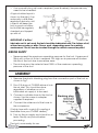
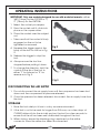
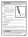
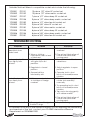
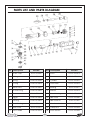
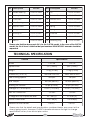
REVERSIBLE RATCHETS
MODEL CAT108 (1/2”) & CAT109 (3/8”)
Part Nos: 3120110 & 3120116
OPERATING & MAINTENANCE
INSTRUCTIONS
GC0409
INTRODUCTION
Thank you for purchasing this CLARKE product.
Before attempting to use the reversible ratchet, please read this manual
thoroughly and follow the instructions carefully. In doing so you will ensure the
safety of yourself and that of others around you, and you can look forward to
the reversible ratchet giving you long and satisfactory service.
GUARANTEE
This CLARKE product is guaranteed against faulty manufacture for a period of
12 months from the date of purchase. Please keep your receipt as proof of
purchase.
This guarantee is invalid if the product is found to have been abused or
tampered with in any way, or not used for the purpose for which it was
intended.
Faulty goods should be returned to their place of purchase, no product can
be returned to us without prior permission.
This guarantee does not effect your statutory rights.
ENVIROMENTAL PROTECTION
Do not dispose of this product with general household waste. All tools,
accessories and packaging should be sorted, taken to a recycling
centre and disposed of appropriately.
PARTS & SERVICING
For parts & Servicing, please contact your nearest dealer, or
CLARKE International, on one of the following numbers.
PARTS & SERVICE TEL: 020 8988 7400
PARTS & SERVICE FAX: 020 8558 3622
or e-mail as follows:
PARTS: [email protected]
SERVICE: [email protected]
2
CONTENTS
Introduction ............................................................................................ 2
Guarantee .............................................................................................. 2
Environmental Protection ...................................................................... 2
Parts & Service Contacts ....................................................................... 2
Table of Contents ................................................................................... 3
Overview ................................................................................................ 3
General Safety Precautions .................................................................. 4
Air Supply Requirements ....................................................................... 5
Assembly ................................................................................................ 6
Operation ............................................................................................... 7
Maintenance .......................................................................................... 8
Accessories ............................................................................................ 8
Troubleshooting ...................................................................................... 9
Parts Lists and Diagrams ..................................................................... 10
Technical Specification ....................................................................... 11
Vibration Emissions .............................................................................. 12
Declaration of Conformity .................................................................. 14
OVERVIEW
The CAT108 and CAT109 Reversible Ratchets are ideal for use in garages and
workshops. The tool features a steel angle head & aluminium body, front
exhaust & ergonomic grip.
Unpack and lay out the components, checking against the following list. Any
damage or deficiency should be reported to your CLARKE dealer
immediately.
•
Reversible ratchet
•
Male Snap Connector
•
Bottle of Airline Oil
•
Operators Manual (this document)
Your reversible ratchet has been designed to give long and trouble free
service. If, however, having followed the instructions in this booklet carefully,
you encounter problems, take the unit to your local CLARKE dealer.
3
SAFETY PRECAUTIONS
WORK ENVIRONMENT
• Keep the work area clean and tidy.
• Dress appropriately - Do not wear loose clothing or jewellery. Tie long hair
out of the way.
• Keep children and visitors away - Do not let children handle the tool.
Make sure that any other persons in the work area are dressed suitably
and are wearing eye and ear protectors.
• Keep the air supply hose away from heat, oil and sharp edges.
• Do not fit the tool to any stand or clamping device that may damage the
tool.
GENERAL USE
• Stay alert and use common sense - do not use the tool when you are tired
or under the influence of alcohol, drugs or medication.
• Always wear eye protection when using the tool - eye protection must
provide protection from the front and the side.
• Always wear ear protectors when using the tool.
• Do not over-reach - keep proper footing and balance at all times.
• Never use any type of bottled gas as a source of power for the tool.
• Do not connect the air supply hose with your finger on the trigger of the
tool.
• Do not exceed the maximum pressure for the tool: 90 psi / 6.2 bar.
• Check hoses for leaks or worn condition before use and ensure that all
connections are secure.
• Do not use the tool for any other purpose than that described in this
booklet.
• Do not carry out any alterations or modifications to the tool.
• The tool should be serviced as required by your CLARKE dealer.
• Never use the tool if it is defective or operating abnormally.
• ALWAYS ensure the workpiece is firmly secured leaving both hands free to
control the tool.
• ALWAYS ensure the tool has stopped before putting it down after use.
• ALWAYS ensure that any attachments are correctly fastened before
connecting the tool to the power supply.
4
• Always disconnect from the air supply when:
a)
Performing any maintenance.
b)
The tool is not in use.
c)
The tool will be left unattended.
d)
Moving to another work area.
• Avoid damaging the tool for example by applying excessive force.
• ALWAYS maintain the tool with care. Keep it clean for best and safest
performance.
• Quick change air-line couplings should not be located at the tool. They
add weight and could fail due to vibration.
• DO NOT force or misuse the tool. It will do a better and safer job at the
rate for which it was designed.
• This tool vibrates during use. Vibration may be harmful to your hands or
arms. Stop using the tool if discomfort, a tingling feeling or pain occurs and
seek medical advice before resuming use.
TRANSPORTATION
• Never carry the tool by the air supply hose.
• Never carry the tool with your finger on the trigger.
STORAGE
• When not in use the tool must be disconnected from the air supply and
stored in a dry place out of the reach of children (preferably in a locked
cabinet).
• Avoid storage in environments where the temperature is below 0oC.
AIR SUPPLY REQUIREMENTS
WARNING: COMPRESSED AIR CAN BE DANGEROUS. ENSURE THAT YOU
ARE THOROUGHLY FAMILIAR WITH ALL PRECAUTIONS RELATING TO THE
USE OF COMPRESSORS AND COMPRESSED AIR SUPPLY.
• Air compressors used with the tool must comply with the appropriate
European Community safety directives.
• Use only clean, dry, regulated compressed air as a power source.
• A build up of moisture in the air compressor will accelerate wear and
corrosion in the moving parts. Ensure any moisture is drained from the
compressor daily and the inlet filter is kept clean.
5
• If an unusually long air hose is required, (over 8 metres), line presure may
need to be increased.
A typical airline layout is
shown on the right. If an
automatic in-line filter/
regulator/lubricator unit
is used it will keep the
tool in good condition,
but should be regularly
checked and topped
up with oil.
IMPORTANT: If a filter/
lubricator unit is not used, the tool should be lubricated with 2 to 6 drops of oil,
at least once a day or after 2 hours work, depending upon the working
environment. The oil can be inserted through the airline connection point.
AIRLINE SAFETY
• Never exceed the maximum operating pressure for the tool. A pressure of
90psi with a flow of 4 cfm is required. Too high an air pressure will shorten
the life of the tool due to excessive wear.
• The air hose must be rated at least 150% of the maximum operating
pressure of the tool.
ASSEMBLY
1. Remove the plastic blanking plug from the connection port of the tool as
shown in Fig 1.
2. Pour 2-3 drops of CLARKE airline oil into
the air inlet. This should be done
regardless of whether or not a
lubricated air supply is to be used.
3. Connect a suitable hose to the tool as
shown. Use the screw-in adapter
supplied if required.
4. Connect the other end of the hose to
the compressor.
(A whip hose with a quick fit coupling is
available from your CLARKE dealer).
5. Turn on the air supply and check for air
leaks. Rectify any found before
proceding.
The tool is now ready for use.
6
Fig 1
OPERATING INSTRUCTIONS
IMPORTANT: Only use sockets designed for use with a ratchet wrench;- either
3/8" (10mm) for the CAT109 or 1/
2” (13mm) for the CAT108.
1
Select the socket you require.
2. Press the socket until it clicks into
place on the square drive.
3. Place the socket over the subject
nut.
• Take care that the socket is firmly
engaged on the nut to be
tightened or removed.
Fig 2
4. Squeeze the trigger against the
body of the tool to start as in Fig
2.
5. Release the trigger to stop the
tool.
6. Always ensure the tool has
stopped before putting it down.
7. To change the direction, twist the
control at the tip of the tool to
either ‘F’ for forward or ‘R’ for
reverse as in Fig 3.
Fig 3
DISCONNECTING THE AIR SUPPLY
1. Do not disconnect the air supply hose until the compressor has been shut
down and the compressed air pressure released.
2. Once the pressure has been released, disconnect the air supply hose from
the tool.
STORAGE
1. Store the tool safely in its box in a dry, secure environment.
2. If the tool is not to be used for longer than 24 hours, run a few drops of
CLARKE airline oil into the air inlet and run the tool for a few seconds to
ensure that the oil has been well distributed throughout the tool.
3. When storing, ensure the blanking plug is replaced on the airline
connector once the airline has been disconnected.
7
MAINTENANCE
WARNING! Make sure that the ratchet wrench is disconnected from the air
supply before starting any cleaning or maintenance procedures.
DAILY
• Drain water from the compressor air
tank and air-line.
• Pour a few drops of CLARKE air line
oil**, into the air inlet. This should be
carried out regardless of whether or
not an air line lubricator is used. If an
air-line lubricator is not used, this
procedure should be repeated after
every two to three hours of use.
WEEKLY
• Check the air inlet screen filter shown
in Fig 4 and clean if necessary.
Air Inlet Screen
Filter (located
here)
Fig 4
CLEANING
• Keep the body of the tool clean and free from debris. Grit or gum deposits
in the tool may reduce efficiency.
• After extensive use, remove the inlet screen filter and flush out the
mechanism with gum solvent oil or an equal mixture of SAE No10 oil and
paraffin. Allow to dry before use.
SERVICE AND REPAIR
• Any major servicing and repairs should be carried out by your local
CLARKE dealer.
PERFORMANCE
Please note that factors other than the tool may effect its operation and
efficiency such as reduced compressor output, excessive drain on the airline,
moisture, or restrictions in the line, or the use of connectors of improper size or
poor condition which will reduce air supply.
**Clarke Airline Oil is available from your CLARKE dealer part no. 3050825.
ACCESSORIES
A wide range of accessories are available including filter/regulators,
lubricators, high pressure hoses, etc. Contact your CLARKE dealer for further
information, or call CLARKE International on 01992 565333.
8
Suitable Ratchet Wrench compatible socket sets include the following:
1700431
PRO31
10 piece 1/2” drive AF socket set
1700432
PRO32
10 piece 1/2” drive metric socket set
1700437
PRO37
7 piece 1/2” drive deep AF socket set
1700438
PRO38
9 piece 1/2” drive deep metric socket set
1700452
PRO52
6 piece 1/2” drive hex bit socket set
1700429
PRO29
9 piece 3/8” drive AF socket set
1700430
PRO30
9 piece 3/8” drive metric socket set
1700435
PRO35
8 piece 3/8” drive deep AF socket set
1700436
PRO36
8 piece 3/8” drive deep metric socket set
1700451
PRO51
6 piece 3/8” drive hex bit socket set
TROUBLESHOOTING
SYMTOM
Tool runs at normal
speed but slows
under load.
Tool runs slowly. Air
flows lightly from
exhaust.
Tool will not run. Air
flows freely from
exhaust.
PROBLEM
1. Motor parts worn.
SOLUTION
1. Return to dealer for
overhaul
2. Worn or sticking
mechanism due to lack
of lubricant.
1. Motor parts jammed
with gum &/or dirt
particles.
2. Drip air tool lubricating oil
into air inlet and soak
moving parts.
1. Examine inlet air filter for
cleanliness.
2. Regulator in closed
position.
2. Adjust regulator to open
position.
3. General air flow
blocked by dirt.
3. Operate tool in short
bursts of forward/reverse
rotation.
1. Disconnect air supply &
rotate tool assembly
manually.
1. Motor vanes stuck due
to buildup of foreign
materal.
2. Try operating tool in short
bursts of forward/reverse
rotation.
3. Tap motor housing gently
with rubber mallet.
Tool will not shut off.
1. Damaged or dislodged
throttle O-rings.
4. Drip air tool lubricating oil
into air inlet and soak
moving parts.
1. Replace O-ring
In the event that any of the above situations occurs, requiring the dismantling
and overhaul of the tool, contact your CLARKE International Service
Department on 020-8988-7400.
9
PARTS LIST AND PARTS DIAGRAM
N o D e s c r ip t io n
Part No
No
Description
Part No
1
Screw Cap
RONCAT10801
13
Rotor
RONCAT10813
2
O-Ring
RONCAT10802
14
Pin
RONCAT10814
3
Spring
RONCAT10803
15
Cylinder
RONCAT10815
4
O-Ring
RONCAT10804
16
Front Plate
RONCAT10816
5
Va l v e S t e m
RONCAT10805
17
Bearing
RONCAT10817
6
Air Inlet Plug
RONCAT10806
18
Washer
RONCAT10818
7
Pin
RONCAT10807
19
Gear Housing
RONCAT10819
8
Tr i g g e r
RONCAT10808
20
Idler Gear
RONCAT10820
9
Housing
RONCAT10809
21
Idler Gear Pin
RONCAT10821
10
Rear Bearing
RONCAT10810
22
Idler Gear Seat
RONCAT10822
11
Rear Plate
RONCAT10811
23
Clamp Nut
RONCAT10823
12
Rotor Blade
RONCAT10812
24
Nose Section
RONCAT10824
10
N o D e s c r ip t io n
Part No
No Description
Part No
25
Needle Bearing
RONCAT10825
34
Pin
RONCAT10834
26
Bearing Shell
RONCAT10826
35
Ratchet Pawl
RONCAT10835
27
Crankshaft
RONCAT10827
36
Ratchet Anvil
RONCAT10836
28
Drive Bushing
RONCAT10828
37
Steel Ball
RONCAT10837
29
R a t c h e t Yo k e
RONCAT10829
38
Spring
RONCAT10838
30
Spring
RONCAT10830
39
Spring
RONCAT10839
31
Locking Pin
RONCAT10831
40
Steel Ball
RONCAT10840
32
Reverse Switch
RONCAT10832
41
Washer
RONCAT10841
33
Wa s h e r
RONCAT10833
42
Retaining Ring
RONCAT10842
Please note that the above parts list is for the CAT108 model. In the case of the CAT109
model, the list of items is identical but part numbers RONCAT10901 onwards should be
requested.
TECHNICAL SPECIFICATION
Feature
Specification
Model
CAT108
CAT109
1/2" (13mm)
3/8" (10mm)
1.2 kg (2.4 lbs)
1.2 kg (2.4 lbs)
Dimensions (l x w x h)
265 x 48 x 42 mm
265 x 48 x 42 mm
Free Running Speed
160 rpm
160 rpm
Max Torque
50 ft/lb (68N.m)
50 ft/lb (68N.m)
Working Air Pressure
90 psi (6.2 bar)
90 psi (6.2 bar)
4 cfm (114 l/min)
4 cfm (114 l/min)
1/4" BSP
1/4" BSP
A-weighted sound pressure level
92.1 dB (A)
91.5 dB (A)
Sound Power Level
103.1 dB(A)
102.5 dB(A)
0.8 m/s2
0.8 m/s2
Square Drive
Weight
Average Air Consumption
Inlet Air Connection
Vibration at the handle
Please note that the details and specifications contained herein, are correct at the
time of going to print. However, CLARKE International reserve the right to change
specifications at any time without prior notice.
11
VIBRATION EMISSIONS
HAND-ARM VIBRATION
Employers are advised to refer to the HSE publication “Guide for Employers”.
All hand held power tools vibrate to some extent, and this vibration is
transmitted to the operator via the handle, or hand used to steady the tool.
Vibration from about 2 to 1500 herz is potentially damaging and is most
hazardous in the range from about 5 to 20 herz.
Operators who are regularly exposed to vibration may suffer from Hand Arm
Vibration Syndrome (HAVS), which includes ‘dead hand’, ‘dead finger’, and
‘white finger’. These are painful conditions and are widespread in industries
where vibrating tools are used.
The health risk depends upon the vibration level and the length of time of
exposure to it……in effect, a daily vibration dose.
Tools are tested using specialised equipment, to approximate the vibration
level generated under normal, acceptable operating conditions for the tool
in question. For example, a grinder used at 45° on mild steel plate, or a
sander on softwood in a horizontal plane etc.
These tests produce a value ‘a’, expressed in metres per second per second,
which represents the average vibration level of all tests taken, in three axes
where necessary, and a second figure ‘K’, which represents the uncertainty
factor, i.e. a value in excess of ‘a’, to which the tool could vibrate under
normal conditions. These values appear in the specification panel below.
MODEL No: CAT108 & CAT109
DESCRIPTION: REVERSIBLE RATCHETS
Declared vibration emission value in accordance
with EN12096
Measured vibration emission value - a: less than
2.5m/s2
Values determined according to EN28622-1
12
You will note that a third value is given in the specification - the highest
measured reading in a single plane. This is the maximum level of vibration
measured during testing in one of the axes, and this should also be taken into
account when making a risk assessment.
‘a’ values in excess of 2.5 m/s2 are considered hazardous when used for
prolonged periods. A tool with a vibration value of 2.8 m/s2 may be used for
up to 8 hours (cumulative) per day, whereas a tool with a value of 11.2 m/s2
may be used for ½ hour per day only.
The graph below shows the vibration value against the maximum time the
respective tool may be used, per day.
The uncertainty factor should also be taken into account when assessing a
risk. The two figures ‘a’ and ‘K’may be added together and the resultant
value used to assess the risk.
It should be noted that if a tool is used under abnormal, or unusual conditions,
then the vibration level could possibly increase significantly. Users must always
take this into account and make their own risk assessment, using the graph
above as a reference.
Some tools with a high vibration value, such as impact wrenches, are
generally used for a few seconds at a time, therefore the cumulative time
may only be in the order of a few minutes per day. Nevertheless, the
cumulative effect, particularly when added to that of other hand held power
tools that may be used, must always be taken into account when the total
daily dose rate is determined.
13
DECLARATION OF CONFORMITY
14
DECLARATION OF CONFORMITY
15