1
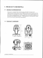
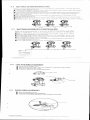
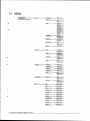
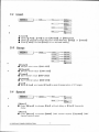
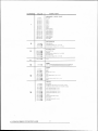
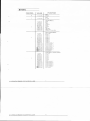
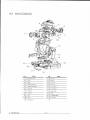
Stellar60 Spot - 60 Watt LED Moving Head
Ste lla r60 Spot
tt LID Moving Heed Spot
[email protected]
832-623-9377
T
BLE OF CONTENTS
PART 1 PRODUCT (GENERAL)
1.1--PRODUCT INTRODUCTION
1.2-PRODUCT OVERVIEW
I.3-TECHNICAL SPECIFICATIONS
1.4--PHOTOMETRIC DATA
1.5-SAFETY WARNING
1
1.
1.
2.
3.
3.
PART 2 INSTALLATION
2. 1-4,10 UNTING
2.2--SETTING UP(MASTER/SLAVE)
2.3--SETTING UP(DMX512 CONTROLLER)
4.
4.
5.
7
2.4--LED PCB REPLACEMENT
2.5-G080 REPLACEMENT
2.6--FUSE REPLACEMENT
6.
6.
7.
PART 3 DISPLAY R1NEL OPERATION
3. 1--BASIC
3.2-MENU
3.3-INTRO
3.4--INVERT
3.5--RANGE
3.6--SPECIAL
3.7-EDIT
3.8--DEFAULT
PART 4 USING A DMX512 CONTROLLER
4.1--BASIC ADDRESSING
4.2--CHANNEL ASSIGNMENT
PART 5 APPENDIX
5.1-TROUBLE SHOOTING
5.2--MAINTENANCE
7.
7.
8.
9.
10.
10.
10.
11.
11.
12.
12.
12.
16.
16.
17.
PRODUCT(GENERAL)
1.1 PRODUCT INTRODUCTION
This product isdesigned for indooruse only. Suitable for stage,bar or
nightclub applications. Directinput of DMX512 signal allows thefixtures to be
controlled from anyDMX512 controller. The fixture isfully programmable with
one custom programavailable and is supplied with twoautomatic programs (all
accessible from DMX512controller). This productcan be operatedas a single
unit or with multiple units forlarge applications.
1.2 PRODUCT OVERVIEW
PRODUCT(GENERAL)
1 3 PRODUCT SPECIFICATIONS
Electrical
•Voltage:AC 100-240V, 50/60Hz
♦ Rated Power:150W
LED
♦ LED:1PC(60W white)
♦ Cooling:Forced air convection
Optical System
♦ Focus:Electronic focus
♦ Dimmer:0-100%
♦ Strobe:0-20Hz
♦ Rotating 3-facet Prism
Operation
♦ Control mode: DMX512/Master-Slave/Auto/C ustom/ Sound
♦ LCD display
♦ DIV1X512 Chs:11CHS/ 14CHS
Pan/Tilt
♦ Pan 540° Tilt 270°
♦ Pan/Tilt speed
♦ User-selectable Pan/Tilt ranges
♦ Reverse Pan/Tilt movement
Rotating Gobo
♦ 7 Gobo (interchangeable)
♦ Gobo-flow effect
♦ Gobo shake
♦ Bi-directional rotation
Static Gobo
♦ 9 Gobo
♦ Gobo-flow effect
♦ Gobo shake
Color
♦ 8 dichroic -filters + white
♦ Rainbow - flow effect
Other features
♦ Custom program (255 steps)
♦ Size:295x290x485mm
♦ Weight:14kg
1 PRODUCT(GENERAL)
1.4 PHOTOMETRIC DATA
1056
470
264.4
169 2 1_127
I ■
(
(
ITT
'11081
1.5
6(166 3)
i
8(221 7)
,
10 (
277
)
'2 1'(
8o'r:se"
te`.7).)
) ))
SAFETY WARNING
IMPORTANT:
• This product must be installedby a qualifiedprofessional.
• Always operatethe equipment asdescribed in the user manual.
• A minimum distance of 0.5m must be maintainedbetween the equipment
and combustible surface.
• The product must always be placed in a well ventilated area.
• Always make sure that the equipment is installedsecurely.
• DO NOT stand close tothe equipment andstare directly intothe LED light
source.
• Always disconnectthe power supplybefore attempting andmaintenance.
• Always make sure that thesupporting structure is solid and can support
the combined weight of the products.
• The earth wire must alwaysbe connected tothe ground.
• Do not touchthe power cablesif your handsare wet.
• This product leftthe place ofmanufacture in perfectcondition. In orderto
maintain this condition and for safe operation, the usermust always follow
the instructions andsafety warnings describedin this usermanual.
• Avoid shaking or strong impacts to anypart of theequipment.
• Make sure thatall parts ofthe equipment arekept clean andfree of dust.
• Always makesure that the power connections areconnected correct and
secure.
If there is any malfunction ofthe equipment, contactyour distributor
immediately.
• When transferring theproduct, it isadvisable to usethe original packaging
in which the product left thefactory.
• Shields, lenses or ultraviolet screens shallbe changed ifthey have
become damaged tosuch an extentthat their effectiveness is impaired.
• The lamp (LED) shall bechanged if it has become damaged or thermally
deformed.
•
1
PRODUCT(GENERAL)
2 INSTALLATION
2.1
MOUNTING:
• The LED fixture can be operatedin any position at any angle. When mounted
on a flat surface, the surface must be strong enough to support 10 times the
weight of thefixture and stable so that there will be nodamage caused tothe
fixture or surrounding people or objects because of movements of the fixture
on the surface.
• When the unit is mounted in a hanging position.the fixture isattached using the
mounting brackets anda standard trussclamp or other clamping device. The
mounting brackets suppliedare mounted using quick-release locks allowing
simple mounting orremoval.
glr.Z
4:>' CLAMP
BRA
SAFTf CABLE
,ET
UPRIGHT
HANGING
IMPORTANTSAFETY NOTE!!
Always use a safety cable when installing this unit!!
Be sure thatthe safety cable is connected toa solid load-bearing structure.
2 INSTALLATION
2.2 SETTING UP (MASTER/SLAVE)
When units are connected in seriesusing DMX512 signalcable connect the units
as shown inthe diagram below
• Connect the (male)3 pin connectorside of the DMX cable to the output (female)3
pin connector ofthe first (MASTER) fixture.
• Connect the endof the cable coming from the MASTER fixture whichwill have a
(female)3 pin connector to the input connector ofthe next fixture consisting of a
(male) 3 pin connector.
*Then proceed toconnect from the output as statedabove to the input of the
following fixture andso on.
*Set the firstunit in theseries to on e of the STAND ALONE modes as de scribedin
section 2.2
• All other unitsin the series should be setto <SLAVE> from the <operation> menu.,
2.3 SETTING UP (DMX512 CONTROLLER)
When units are connected in series to a DMX512 controller and other
DMX512 equipment, connect the equipment as shown in the diagram
below.
*Connect the (male)3 pin connectorside of the DMX cable tothe output
(female) 3 pinconnector of the controller.
• Connect the end of the cable coming from the controller which will
have a (female)3 pin co nnectorto the input connector of the next fixture
• consisting of a(male) 3 pm connector.
Then proceed to connect from the output as stated above to the input of
the following fixture an d so on.
• lf over 32pcsfixtures connected ,the amplifier is needed.
14,
L 1011
OKIVCX.LOC
2 INSTALLATION
2.4
LED PCB REPLACEMENT
•
•
•
Take off the head cover.
Remove the fan cover, fan, fan supports, heat sink step bystep
Replace the new LED PCB.
•
Install all parts on the original position.
.
HEAD COVER
Fan support-
FAN COVER
Fan
Heat sink
LED PCB
2.5
GOBO REPLACEMENT
•
•
•
Unlock the gobocover ;
Take out thetarget rotating gobo.
Install the newrotating gobo, lock thegobo slot door.
• 0130 SLOT DOOR
2 INSTALLATION
0
2.6
FUSE REPLACEMENT
•
•
•
•
Remove the safety cap by a screwdriver.
Fetch the oldfuse from safetycap.
Install a newfuse.
Install the safety cap.
3 DISPLAY PANEL OPERATION
3.1
BASIC
MENU ] Scroll through themain menu orexit from thecurrent sub-menu
(ENTER] Enter the currentlyselected menu orconfirm the currentfunction
value
DOWN] Scroll 'DOWN' throughthe menu list or decrease thevalue of the
current function
UP ] Scroll 'UP' throughthe menu listor increase thevalue of the
Current function
0 0 0 0
MENU ENTER DOWN UP
2 INSTALLATION
•
-
3.2
MENU
MENU
INTRO
)
ADDRESS
)
RESET
) -...- NO
RUN
)
(001-512)
YES
)
)
)
DMX512
)
A=1)
AUTO 2
)
SOUND 1
)
HD2)
SOU
CUSTOM
)
TEST
CHANNELS
) -
DISPLAY
KEYLOCK
INVERT
SLAVE
)
BASIC
ADVANCED
)
)
60 CLOSE
BRIGHT
)
)
NO
)
INFO
)-
EDITION
)
PAN
)
NORMAL
REVERSE
)
TILT
)-
NORMAL
COLOR
)
REVERSE
)
STEP
)
)
LINEAR
)
USE
RANGE )
C)
YES
ITAt)
AT --- MOO
25)
--:P/FINISH
(E00 --)
5)
j
T/START
(000-255 )
)
TiFINISH
(000-255)
)
N0
YES
SPECIAL
BLACK
NO
YES
)
RESET
EMS
SYSTEM
EDIT
STEP
)
000 -2L))
)
1,
PA/
(000 -255)
)
000
XYSPEED
) -_- 000-255)
COLOR
}
(000-255)
)
00801
)
000 -255)
)
000-255)
)
(000-255)
)
=12)
GOB 02ROT )
PRISM
)
(000-255)
)
FOCUS
)
(000-255)
)
(000-255)
)
DIMMER
3 DISPLAY PANELOPERATION
-
,
13 E )
STROBE
TIME
D efault
II co
(0002)
USE
)
DEFAULT
)
NO
YES
NO
YES
)
NO
)
YES
)
3.3 INTRO
MENU
)
...Us ADDRESS )
itESET)
RUN
CHANNELS
)
A1)11)
AU -102)
SOUND 1 )
SOUND 2
)
CUSTOM
)
TEST
)
SLAVE)
DMX512
)
BASIC
)
ADVANCED )
DISPLAY
)
60 CLOSE
BRIGHT
KEY 1.C1
INFO
•
)
)
NO
)::EDITION
)
[Address]
Enter [Address] to set the DMX Address, which is from(001 512)
-
[Reset]
• In order torest custom modest to default, select [Reset]
•
[Run]
Enter [Run] to select tne operation mode: [DMAX512] [Autall ;
[Auto2] : [Sound 1] ; [Sound 2] [Custom] : [Test] ; [Slave]
•
[Channels]
Enter [Channels] to select the DMX channel modes: [Basic] ;
[Advanced] .
•
[Display]
Enter Display] to select thelighting time ofthe LCD displaypanel.
[Keylock]
Enter the [Keylock] mode to select whether the accesspassword is on
or off.
• When the fixture is set as PASS [ON] after 30 seconds or turn on the
fixture next time,the fixture will need an accesspassword to enterthe
display menu control.
•
Note: The factory access password is [UP] + [DOWN] + [UP]
+ [DOWN] , then press [ENTER] to confirm the access
•
3 DISPLAY
[Info]
Enter [ Info] to see the version of the software.
PAN ELOPERATION
3.4
Invert
MENU
Invert
Pan
Normal
Revers e
)
Norm al
)
Reverse )
Color
)
Step
)
Linear
)
Use
•
)
Tilt
Lr.i. No
Yes
Invert]
• Select [ Pan] / [ Tilt] to set [Normal] or [Reverse]
• Select [ Color] to select thecolor wheel flowway [Step] or [linear]
• Enter [ Use] and set [Yes] to run thenew setting
3.5
Range
MENU
J
_.— Range
P ta
(000-255)
)
P •Firist
t )
1000-255)
)
Tistat
)
T/Finish
) irmantr. (000-255)
)
Use
)
)
No
Yes
3.6
•
[P/start]
Set pan startvalue [000 255]
•
[P/Finish]
Set pan finish value [000 255]
•
ET/start ]
Set Tilt start value (000 255]
•
[T/Finish]
Set Tiltfinish value [000 255]
•
[ Use]
Enter
-
-
-
-
Use] and select [Yes] to open theoperation of X/Y angle
Special
MENU )
Special
)
B la ck
Yes
Reset
•
No
)
2 Dm x
System
[Black]
Enter [Black] to choose [No] without delay or [Yes] 3seconds
delay
[Reset]
•
Enter [Reset] to choose [DMX] DMX control resetor [System] DMX
cannot control reset
3 DISPLAY PANEL OPERATION
3.7 EDIT
MENU
EDIT
m.-4,- Step
)
(000-255)
)
Pan
)
(000-255)
)
Tilt.
J
(000-255)
)
(000-255)
)
Speed
Color
)
--_--- (000-255)
)
Cobol
)
(000-255)
)
Dobo2
)
(000-255)
)
Gobo.rot
)
(000-255)
)
Prism
)
(000-255)
Focus
)
(000-255)
Dimmer
)
(000-255)
Strobe
)
(000-
)
Time
I
(000-255)
Use
)
tlo)
Yes
)
Edit ]
• Enter the [ Edit ] mode to editthe custom programsby adjusting the
value of [Step] , [Pan] , [Tilt] , [Speed] , [Color] , [Gobo 13 ,
[Gobo 2] , [Gobo.rot] , [Prism] , [Focus] , [Dimmer] , [Strobe] ,
[ Time]
• Enter [ Use] and select [Yes] to run thesteps user need
.
Note: if user wantto circulate thecreated steps, pleaseset the last step's
[Time] as 0
For example, there are 3 steps, the setting shouldbe like belowed:
Step 1 [Time] = 4
Use] = Yes
Step 2 [Time] = 5
[ Use] = Yes
Step 3
Time] = 0
[ Use] = Yes
[
3.8 DEFAULT
MENU
ult
Defa
Default
No
Yes
•
[ Default]
This functions willreset all settingto the original factory setting
3 DISPLAY PAN EL OPERATION
4 USING A DMX51 2 CONTROLLER
4.1
BASIC ADDRESSING
.• Connect all of the units in series using standard DMX512 signal cable .
Set the DMX512 address inthe [DMA menu.
• It is possible to havethe same DMX address or independent addresses for each
fixture
4.2
6
CHANNEL ASSIGNMENT
Note This product have two DMX512 channel configuration:
.
and BA Si
EADVA'ICED]
ADVANCED
C HANNEL
FUNCTION
VALUE
PAN
0 4=0 Mi6
0,5 t III.
0 C.> ZI6
PAN FINE
hit onuctor pa b ol*ie@e II
ooc ms
TILT
0-270°
0 ‘77Vr295
TILT FINE
f1.< costrotortlemoutme ■ 1
2
3
4
PAN/TILT SPEED
1:1.
■ 255
F tom
Os t to I bse
CO LO R WHEEL
tp., 44§v).9 v gi
HV P.Mn
Ortr t
Red
Afar:
Otte rat
Corm
°rave
11,1
whims
lard arm
tattooer art. titer
FIXED G OB 0 WHEEL
.T P)Av s ai rms , "m4m Am
Wt8(1 11 011088M
Mai
" 9 "-Eg
7
4 USINGA DMX512r:ONTROLLER
50 00110
0080 1
0050 2
001103
00110 •
0050 5
001106
001107
00110 8
00 10 S
5
awma 505.5
Stekti5 teat
aakrlo teat 7
9,341rii 00110 5
avaing onto 5
biro taro a
9 t7t7t7
00-40 3
among fallo
2
9-.114,011000 1
710.1 exec!
12
CHANNEL
FUNCTION
VALUE
GOSONIHEEL 150080 SHAKE
MIIII8II448IIM 4II
°2 RMS2 ,°,532 U1
NO Gobs
Gobot
Gobo 2
Gobo 3
Gobs 4
Gobo 5
Gobo S
Gobo 7
Shaking gobo 7
Shaking gobo ik
Shaking gobo 5
Shaking gobo a
Shaking gobo 3
Shaking gobo 2
Shaking gobs I
Flowettect
G080 ROTATION
9
0.3.780
bes3=7 ISA
isa<=esi2S5
Gobo indexing
Clock)Mae rotating Irmo slowtotad
Anti-clockwise rotating nom stowtoNst
ROTATING PRISM
11 13 01
10
000s3=:>23S
NO FUNCTION
Rotation
Anti-clockwise rotating trow Posstotast
NO FUNCTION
Clodivese rotating Pon slowtotast
Focus
11
OIMMER
12
CK=>2.55
' Bright
Oat*
STROBE
""-7
UU U !!
13
Clone
Open
Stiobei Slow / Fast
Open
Ruts. Krone view Slows Fast
Open
Random strobe attest Siow • S as
Open
CONTROL
No function
Pantlitt black activated (activated at er3 secs)
Pantlitt black Pam:heated (activateo Met 3 secs)
Auto) (activated <Met 3sisos)
Aut02 (activated artm 3 secs)
Sound I (activated after 3 secs)
14
Sound 2(activated offer 3 secs)
:
Custom
Um
No function
Teat (activated ales 3 secs)
Reset (activated alter 3secto
No emotion
4 USINGA DMX512CONTROLLER
13
BASIC
CHANNEL
FUNCTION
VALUE
PAN
0,-, 255
0-540•
TILT
OP255
0-270'
COLOR WHEEL
1' I NOD O-
88 88II NM
Green
Orange
Blue
Light blue
Light Green
Rainbow or linear effect
FIXED GOBO WHEEL
NO G080
GOBO t
GOBO 2
GOEI0 3
G0804
0080 5
00806
GOBO 7
G0808
G0809
Shaking gobo 9
Shaking gobo 8
Shaking gobo 7
Shaking gobo 6
Shaking gobo 5
Shaking gobo 4
Shaking gobo 3
Shaking gobo 2
Shaking gobo I
Flow effect
GOBO WHEEL I SGOBO SHAH
am N n
amm lo mm8 m1 gpoim pgm m
5
While
Red
Yellow
Magenta
4 USINGA DMX512CONTROLLER
OWN
gg
4 USINGA DMX512CONTROLLER
NO Gob,
Gobo I
Gob° 2
Gobo 3
Gobo 4
Gobo 5
Gobo 6
Gobo 7
Shaking gobo 7
Shaking gobo 6
Shaking gobo 5
Shaking gob, 4
Shaking gobo 3
Shaking gobo 2
Shaking gobo I
Flow effect
5.2 MAINTENANCE
No
5 APPENDIX
No
ITEM
Front lense corer
72
2
Prism
13
3
Motet
ITEM
Base fan
Er
a ;t PCB
15
Base corer
LED PCB
17
ALP
Heal 90li
18
Power socket
On/Off
4
Moroi dryer PCB
5
Rotalion gobo wheel
6
7
socket B
=.5ckei A
s
Head fan
is
9
Arm
20
Fixed gobo *11001
10
Motor
21
r
11
Display PCB
•17•
*9%1