1
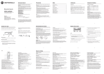
DNR-101i /111i
Guide to Installation and Operation
M752-9900-100
Copyright 2003 Miranda Technologies Inc.
Specifications may be subject to change.
Printed in Canada
November 2003
Miranda
Technologies inc.
3499 Douglas-B.-Floreani, St-Laurent
(Québec) Canada, H4S 2C6
Digital Noise
Reducer /
Digital Noise
Reducer w. MNR
DNR-101i / 111i
imaging Series
GUIDE TO INSTALLATION AND OPERATION
Warranty Policies
Warranty Statement
Miranda Technologies Inc. warrants that the equipment it manufactures shall be free from defects in material and workmanship
for a period of two (2) years from the date of shipment from the factory. If equipment fails due to such defects, Miranda
Technologies Inc. will, at its option, repair or provide a replacement for the defective part or product. Equipment that fails after
the warranty period, has been operated or installed in a manner other than that specified by Miranda, or has been subjected to
abuse or modification, will be repaired for time and material charges at the Buyer’s expense.
All out-of-warranty repairs are warranted for a period of ninety (90) days from the date of shipment from the factory.
Miranda Technologies Inc. makes no other warranties, expressed or implied, of merchantability, fitness for a particular purpose
or otherwise. Miranda’s liability for any cause, including breach of contract, breach of warranty, or negligence, with respect to
products sold by it, is limited to repair or replacement by Miranda, at its sole discretion. In no event shall Miranda Technologies
Inc. be liable for any incidental or consequential damages, including loss of profits.
Effective January 1, 2002
Warranty Exchange Policies
Miranda Technologies Inc. warrants that the equipment it manufactures shall be free from defects in materials and workmanship
for a period of two (2) years from the date of shipment from the factory. If equipment fails due to such defects, Miranda will
provide repair of the failed unit under the terms of the Miranda warranty.
If the equipment has been proven to be defective on arrival, Miranda will ship a new product in exchange, usually within 36 hours
of factory notification.
If the equipment to be repaired is essential and the customer so requests, Miranda will, at its option, provide a service
replacement or loaner part or product, usually within 36 hours of factory notification, weekends and holidays excluded.
All warranty exchange or loaner parts or products shall be shipped to the Buyer with a packing list clearly describing the items
and stating the date of shipment. Repaired parts or products will be shipped to the Buyer with a similar packing list. In the case
of exchange, the defective products or parts must be returned to Miranda within fifteen (15) days from receipt by the customer of
the exchange product. In the case of a loaner, the loaned products or parts must be returned to Miranda within fifteen (15) days
from receipt by the customer of the repaired equipment.
If the equipment is not returned within fifteen (15) days, as described for either exchanges or loans, A Rental Invoice will be
generated. Rental terms will be fifteen (15) percent of the current list price of the products or parts per month or a fraction
thereof. Before returning the equipment to Miranda Technologies Inc., for any reason, the Buyer must first obtain a Return
Authorization Number from Miranda Technologies Inc. Miranda Technologies Inc will pay freight and insurance charges for the
delivery of the loaner or exchange products or parts. Freight and insurance charges for the return of the defective product or part
will also be paid by Miranda Technologies.
Out-Of-Warranty Repair Policy
Miranda will service out-of-warranty repairs using the following model:
Miranda will charge 15% of the current list price of the product, with a minimum charge of $150. Products whose list price is
under $150 will be replaced at a charge equal to current list prices. In the case of obsolete products, the last published list price
for the products will apply. In the case of a product deemed beyond repair, the customer must purchase a new product at current
retail prices. All out-of-warranty repairs are warranted for a period of 90 days from the date of shipment from the factory. Before
returning the equipment to Miranda Technologies Inc., for any reason, the Buyer must first obtain a Return Authorization Number
from Miranda Technologies Inc.
The Buyer will pay freight and insurance charges for the return of the defective product or part to the manufacturer for repair.
Miranda
Technologies will pay freight and insurance charges for the return of the repaired product or part to the Buyer.
Out-Of Warranty Equipment Updates and Spare Parts Policy
Miranda Technologies will charge cost plus 20% of the parts costs and $40.00 shipping and handling for out-of-warranty
equipment updates, or the sales of spare parts.
DNR-101i/111i |
i
GUIDE TO INSTALLATION AND OPERATION
Safety Compliance Information
Safety Compliance
This equipment complies with:
-
CAN/CSA C22.2 No. 950-95 / Safety of Information Technology Equipment, Including Electrical Business Equipment.
UL Std. No. 1950, 3rd Ed. / Safety of Information Technology Equipment, Including Electrical Business Equipment.
EN 60950:1992 (2nd edition) Incorporating A1, A2, A3, A4, and A11/ Safety of Information Technology Equipment,
Including Electrical Business Equipment.
CAUTION
These servicing instructions are for use by qualified service personnel only. To reduce the risk of electric shock, do not
perform any servicing other than that contained in the operating instructions unless you are qualified to do so. Refer all
servicing to qualified service personnel. Servicing should be done in a static-free environment.
Electromagnetic Compatibility
-
This equipment has been tested for verification of compliance with FCC Part 15, Subpart B, class A requirements for
Digital Devices.
This equipment complies with the requirements of:
EN 55022 Class A, Electromagnetic Emissions,
EN 61000-3-2 & -3-3, Disturbance in Supply Systems
EN 61000-4-2, -3, -4, -5, -6, -8 & -11 Electromagnetic Immunity
How to contact us:
Head Office
Miranda Europe
Miranda Asia
Miranda Technologies Inc.
3499 Douglas-B.-Floreani
St. Laurent (Montreal), Que. H4S 1Y6
Canada
222, 226 Rue De Rosny
93100 Montreuil
France
Mita Nexus Bldg. 2F
1-3-33 Mita, Minato-Ku
Tokyo, Japan 108-0073
Tel
Fax
Toll free:
+33 1 55 86 87 88
+33 1 55 86 00 29
+81 3 5730 2988
+81 3 5730 2973
+1 (514) 333-1772
+1 (514) 333-6914
1-800-224-9828
www.miranda.com
ii
| DNR-101i/111i
GUIDE TO INSTALLATION AND OPERATION
Table of Contents
1
DNR-101i Digital Noise Reducer
DNR-111i Digital Noise Reducer with MNR……………………………………………..……….. 1
1.2
1.3
2
Features…………………………………………………………………………………………….………. 1
Functional Block Diagram……………………………………………………………………………..….. 1
Installation……………………………………………………………………………………..……… 2
2.1 Unpacking………………………………………………………………………………………………..……. 2
2.2 DNR-101i and DNR-111i Mechanical Installation……………………………………………………..….. 2
2.2.1 imaging Quartet, Quartet-C, Quartet-M, Quartet-M-A75, Quartet-M-A110 Frames…………. 2
2.2.2 Imaging Symphonie and Quartet 2 Frame…………………………………………….…………. 2
2.2.3 Imaging Solo Frame……………………………………………………………………………...… 3
2.3 Rear Panel Label………………………………………………………………………………………….….. 3
2.4 DNR-101i/111i Electrical Installation…………………………………………………………………….…. 4
3
Operation……………………………………………………………………………………………..... 6
3.1 iControl Interface………………………………………….………………………………………………..… 6
3.2 Remote Control Using the VTR-100…………………………………………………………………….... 11
3.3 Card Edge Controls……………………………………………………………………………………….… 12
3.4 DNR-101i/111i Menu…………………………………………………………………………………….…..13
4
Specifications……………………………………………………………………………………….. 14
DNR-101i/111i |
iii
GUIDE TO INSTALLATION AND OPERATION
1
DNR-101i Digital Noise Reducer
DNR-111i Digital Noise Reducer with MNR
1.1 Introduction
The DNR-101i and DNR-111i provides Digital Video Noise Reduction of SDI video signals for incoming feed
and compression pre-processing applications. The DNR-101i and DNR-111i perform advanced, 10-bit, 3D
Gaussian noise reduction and variable surface and edge filtering. In addition, the DNR-111i removes
Mosquito noise, using Miranda’s proprietary region-based 3D-MONORD algorithm.
The DNR is well suited to incoming feed applications, reducing the RF noise commonly found in signals
transported by satellite and microwave communication links. In this application, the DNR-101i and DNR-111i
dramatically improves the signal to noise ratio and overall image quality. They can also be effective for
negative gamma film noise reduction. The DNR-101i and DNR-111i are also suited to the pre-processing of
signals prior to digital compression for storage or transmission. Reducing random noise and applying
advanced surface and edge filtering, the DNR-101i and DNR-111i dramatically improve digital compression
quality and efficiency. The DNR-111i is particularly suited for DCT-based compression such as MPEG2
found in Direct Satellite Signals (DSS), Digital Cable, Digital Terrestrial Television and digital recording from
a Digital Video Disk. It removes artefacts and noise from the upstream compression process thus making the
retransmission of the signal cleaner and more efficient.
A user interface consisting of a 4-character dot-matrix display, 4 push buttons and six LEDs simplifies user
selections and allows precise adjustments of the parameters. All of the principal controls and preprogrammed functions are accessible on the front card edge.
1.2 Features
•
•
•
•
•
Serial 4:2:2 input with active loop-through
Serial 4:2:2 outputs (2)
EDH detection and insertion used for encryption
Fully-digital, 10-bit signal processing
Local control accessible on the front panel
1.3 Functional Block diagram
Figure 1.1 Functional block diagram
DNR-101i/111i |
1
GUIDE TO INSTALLATION AND OPERATION
2
Installation
2.1 Unpacking
Make sure the following items have been shipped with the DNR-101i or DNR-111i Digital Noise
Reducer. If any of the following items are missing, contact your distributor or Miranda Technologies
Inc.
•
•
•
DNR-101i or DNR-111i Digital Noise Reducer
Rear panel labels
This manual
2.2 DNR-101i and DNR-111i Mechanical Installation
Due to its audio inputs, the DNR-101i/111i must be mounted within Quartet, Quartet-C, Quartet-M,
Quartet-M-A75 or Quartet-M-A110 or Symphonie imaging frame using Symphonie-R-M or
Symphonie-R-C rear modules. This section describes how to install the DNR-101i/111i in any of
these frames. It is not necessary to switch off the power from these frames when installing or
removing the DNR-101i/111i.
2.2.1 imaging Quartet, Quartet-C, Quartet-M, Quartet-M-A75 and Quartet-M-A110 Frames
To install this module into the audio Quartet frames follow these steps. For a closer look at module
installation and removal, refer to the frame's Guide to Installation and Operation.
1. Remove the frame's front panel by rotating the thumb screws counter-clockwise. Pull on the
handles.
2. Select an empty slot.
3. Carefully place the DNR-101i/111i between a set of module guides and gently push the module
towards the rear of the frame until the module's edge connector is secured to the backplane.
Pull lightly on the module verifying that it does not move.
4. Replace the frame's front panel. Make sure to rotate the thumb screws clockwise in order to
secure it to the chassis.
2.2.2 imaging Symphonie Frame
To install this module into the Symphonie housing frame, follow these steps. To function, the DNR1o1i/111i requires the Symphonie-R-M or -R-C rear module. For a closer look at module installation
and removal, refer to the frame's Guide to Installation and Operation.
1. Remove the front panel door by pulling on the door handles and gently lowering it.
2. Select an empty slot.
3. Carefully place the DNR-101i/111i between the module guides and slowly push the module
towards the rear of the frame until the module's edge connector is secured to its rear module. A
light pressure to mate the connectors may be required. Pull lightly on the module verifying that
it does not move.
4. Replace the front panel door.
2
| DNR-101i/111i
GUIDE TO INSTALLATION AND OPERATION
2.2.3 imaging Solo Frame
To install this module into Solo follow these steps. For a closer look at module installation and
removal, refer to the frame's Guide to Installation and Operation.
1. In order to remove the frame's front panel, gently pull on it.
2. Carefully place the DNR-101i/111i between the module guides and gently push the module
towards the rear of the frame until the module's edge connector is secured to the backplane.
Pull lightly on the module verifying that it does not move.
Replace the frame's front panel.
2.3 Rear Panel Label
Several connector labels have been shipped with the DNR-101i/111i. A label is to be installed on the
frames’ rear panel in order to identify the module's external connectors.
To install the rear panel label on a Quartet, Quartet-C, Quartet-M, Quartet-M-A75, Quartet-M-A110
or a Solo frame, follow these steps while referring to Figure 2.1.
1. Locate the rear panel connectors associated with the DNR-101i/111i module.
2. Apply the label to the connectors and press down until it rests onto the BNC connectors
shoulder.
Figure 2.1 Quartet rear panel label installation
To install the Symphonie and Quartet 2 label, follow these steps while referring to Figure 2.2 (the
Quartet 2 uses the same rear panels as the Symphonie).
1. Locate the rear panel connectors associated with the DNR-101i/111i module. Find the
proper label according to your rear module type.
2. Apply the label to the connectors and press down until it rests onto the BNC connectors
shoulder.
DNR-101i/111i |
3
GUIDE TO INSTALLATION AND OPERATION
Figure 2.2 Symphonie rear panel label installation
2.4 DNR-101i/111i Electrical Installation
Refer to Figure 2.3 below for rear panel connectors location.
Figure 2.3 DNR-101i rear panel label
Figure 2.3 DNR-111i rear panel label
4
| DNR-101i/111i
GUIDE TO INSTALLATION AND OPERATION
4:2:2: serial digital video input
Connect a 4:2:2 serial digital video source to 4:2:2 IN. The DNR-101i/111i accept a 4:2:2 serial digital video
signal in either 525 or 625-line format. This input must conform to the SMPTE 259M-C standard. Make sure
the input 4:2:2 cable has a maximum length of 250 m (850'). An active loop-through is provided. Refer to
section 3.3, Status Monitoring for a description of error and EDH status on the input signal.
Make sure that all serial digital video connections are point-to-point. For instance, there must be a point-topoint connection between the 4:2:2 IN BNC and the source equipment. If a T-connector is used to connect
other equipment, the maximum specified cable length is no longer valid.
4:2:2 OUT : serial digital video output(s)
Two serial digital video with noise reduction are provided by the 4:2:2 OUT connectors. All outputs conform to the
SMPTE 259M-C standard.
GPI : triggering User Presets
The rear panel GPI connector (RJ-69) provides access to the 2 user configurable presets. The following
table provides the connector pin-out.
Pin
1
2
3
4
5
6
7
8
9
10
Function
GND
NC
User Preset 1
NC
GND
GND
NC
User Preset 2
NC
NC
Detection by the microcontroller of an active GPI transition will load the indicated User Preset into the current
operating register. When the GPI input is triggered, the effect is the same as if the indicated preset had been
selected and then loaded (see section 3.3.1 for a detailed explanation). The alphanumeric display will reflect
the user configuration number (1 or 2) when accessing the CONF→LOAD menu.
GPI loading is a “single load” process: it needs to be activated only for a short period (around 1 second)
before it returns to its default state. Activating more than one GPI at the same time will have no effect.
DNR-101i/111i |
5
GUIDE TO INSTALLATION AND OPERATION
3 Operation
The DNR-101i/111i can be controlled in three different ways:
•
The card-edge push-buttons, 4-character display and status LEDs can be used to move through a menu
of parameters and to adjust parameter values.
•
Miranda’s RCP-100 remote control panel can be used to access the same menu structure from a remote
location.
•
Miranda’s iControl system can be used to access the card’s operating parameters from a remote
computer, using a convenient graphical user interface (GUI).
As the graphical interface is the most intuitive and easy-to-use method, it will be used as the basis for
describing the functionality of the DNR-101i/111i. Equivalent means of performing the same functions from
the menus are given in each case. A full description of how to use the card edge controls and the RCP-100
to access the menus is given in sections 3.2 and 3.3.
3.1 iControl Interface
iControl is Miranda’s graphical user interface. Users can remotely access and operate many Miranda
products from a remote computer via an IP interface.
Establish the IP connection to the computer and the frame containing the DNR-101i/111i card.
The iControl graphic interface window
The basic window structure for the DNR-101i/111i is shown in figure 3.1. The window identification line gives
the card type (DNR-101i/111i) and the card ID (116 in the example). The card ID identifies this specific card
to iControl, which may have access to multiple cards of the same type. The text in square brackets is the
Name given by the user to this card (which does not need to match the card type and ID as shown here); the
data entry point is accessed in the Info tab.
There are three main sections in the window itself:
1. The top section displays an icon on the left. This icon reports the status of the signal and its format:
Card status – green if OK, red and highlighted if an error has been detected
If the card status icon is RED indicating an error, an error status message will appear immediately below the
icon.
2. The middle portion of the window changes depending on which of the tabs is selected. Each of the four
panels is described in detail below.
3. The lower section of the window contains 2 buttons, one for recalling factory settings and the other for
saving the current configuration. In the event of a power down or card removal, this will allow the last
configuration to be loaded upon startup. Note that the current configuration is saved automatically after 30
seconds.
6
| DNR-101i/111i
GUIDE TO INSTALLATION AND OPERATION
1
2
3
Figure 3.1 DNR-101i/111i iControl graphic interface window
The Config tab
The Config tab includes basic functions of the DNR-101i/111i; refer to image 3.1 to locate the different
elements.
The Noise Filter Mode is available only with the DNR-111i. Select MNR to access the Block Artefact
Remover in the Filter tab.
MENU:
MODE
→
MNR
The Bypass checkbox allows the video signal to pass through without any noise reduction.
The Split checkbox will output a splitscreen showing on the left side the improved image, and on the right
side the original, allowing the evaluation of the filtering effect.
Using these checkboxes is equivalent as selecting Bypass and Split using the pushbuttons on the front card
edge controls.
The User Presets are six configuration registers in an on-board non-volatile memory. Filter parameters are
saved to these registers, and may be recalled from them.
Select the User Preset to be used through the Select User pull-down box (the current selection is shown).
Then click Save User to store the current configuration in that register
MENU:
CONF
→
SAVE
DNR-101i/111i |
7
GUIDE TO INSTALLATION AND OPERATION
To recall a saved configuration, select the register through the Select User box, then click Load User.
The Filter Tab
The Filter tab contains sliders for filters adjustments, and in the case of the DNR-111i, controls over the
Block Artefact Remover. The best configuration is based on picture content, type of display device and
perceived appreciation. Filtering that is not well suited may degrade considerably image quality instead of
improving it, so change one parameter at a time and oberve carefully the result. The following procedure is
one way to configure efficiently the DNR-101i/111i; details on the filters follow.
1- Set all parameters to 0.
2- Find a video sequence incorporating visually apparent compression artefacts and block effects, such
as those found on a DVD.
3- Activate the Block Effect Remover [set it to ON using the pull-down menu]
4- Set the Block Edge Position [0 to 7] until vertical transitions between compression blocks disappear.
5- Adjust the level of the Detail Enhancer filter, according to the type of display device.
6- Set the level of the 3D Temporal Filter to 3; increase the level if required.
7- Gradually increase the level of 2D Spatial Filter until virtually all mosquito noise is eliminated.
Figure 3.2 The Filter Tab
Detail Enhancer : This filter increases the high frequency level of the image, effectively improving the
sharpness of textures and contours. Adjust this filter according on the type of display device: typically, a
plasma display will require less detail enhancement than a video projector. Note that too much filtering may
8
| DNR-101i/111i
GUIDE TO INSTALLATION AND OPERATION
increase residual noise from the 2D Spatial filtering and 3D Temporal filtering if they are not properly
ajdusted.
Use the slider to control the detail enhancer filter, ranging from 0 to 15. Default value is 0, which sets filtering
to off.
MENU:
DE
Noise Reducer - 2D Spatial Filter: This bidimensional, adaptive filter detects and reduces artefacts and
mosquito noise in the picture caused by MPEG compression. This filter should only be used on noisy signals,
as it may actually add some processing noise to clean pictures. The subjective effect can be seen using a
high-quality video monitor at the output. Too much noise reduction may create a paint-by-number effect on
the image.
Use the slider to control the 2D Spatial Filter, ranging from 0 to 15. Default value is 0. Position 8 sets filtering
to off.
MENU:
2D
Noise Reducer – 3D Temporal Filter: This recurring, motion-adaptive filter is aimed at eliminating random
noise typical of analog video signal transmission. Note that excessive use of this filter may produce streaking
of fine moving details; use according to your picture content.
Use the slider to control the 3D Temporal Filter, ranging from 0 to 15. Default value is 0. Position 3 sets
filtering to off.
MENU:
3D
Block Artefact Remover (DNR-111i only): The Block Artefact Reducer (BAR) helps blending and
diminishing vertical transitions of 8x8 pixel blocks resulting from MPEG compression. These blocks are
apparent in lower transmission, decompressed pictures.
Use the BAR Mode Enable pull-down menu to turn ON or OFF the Block Artefact Remover.
MENU:
BAR
→
ENA
Use the Block Edge Position pull-down box menu to locate the block positions, as the detection of vertical
transition is not automatic. This initial calibration is required to define the zones to be filtered. Settings range
from 0 to 7.
MENU:
BAR
→
BLK
The EDH Tab
The EDH tab is where all the error conditions are reported. The top portion, Error Detected Status, shows a
series of icons which give the status of error flags (EDH, EDA, IDH, IDA, UES, CKS) within various signal
sectors (Active Picture, Full Field, Ancillary).
DNR-101i/111i |
9
GUIDE TO INSTALLATION AND OPERATION
The bottom portion, Error Sensitivity Selection, includes a checkbox for each of the status monitors, allowing
it to be turned on or off. Click on ED & ID to select all except UES. Click Clear All to deselect all status
monitors.
At the bottom is an error counter, which counts up errors detected by the enabled aspects of the EDH (error
detection and handling) system. The counter can be cleared, i.e. reset to zero.
MENU:
Not available through the menu system
Figure 3.5 The EDH Tab
The Info Tab
The Info tab provides the user with information about the DNR-101i/111i card, as shown in figure 3.6.
The boxes titled Name and Comments are editable; the user can enter its own information.
Manufacturer, Vendor, Version and Serial Number display different information that may be asked when
contacting your vendor or Miranda Technologies inc. for service. The Detail button display additional
information useful to Miranda Technologies inc.
The Advanced button displays the card’s unique ID within the iControl system, identifying the DNR-101i/111i
card, the slot and frame into which it is installed, and the URL and port of the frame on the network.
10
| DNR-101i/111i
GUIDE TO INSTALLATION AND OPERATION
The Remote System Administration button at the bottom of the window opens a data entry box titled Joining
Locators, in which the ADD option opens a dialog box in which the user can identify the Locator by its URL.
MENU:
Not available through the menu system
Figure 3.6 The Info Tab
3.2 Remote Control Using the RCP-100
The menu structure of the DNR-101i/111i is also accessible through the use of Miranda’s RCP-100 remote
control panel.
Please refer to the RCP-100 Guide to Installation and Operation for detailed instructions on installing and
operating the RCP-100, and for instructions on how to connect the RCP-100 to the DNR-101i/111i (or any
other supported card) so that the menu can be accessed.
See section 3.4 for a complete listing of the menu structure.
DNR-101i/111i | 11
GUIDE TO INSTALLATION AND OPERATION
3.3 Card Edge Controls
The front card edge consists of four pushbutton switches, six LEDs, and a four-character alphanumeric
display.
The LEDs indicate the status of various parameters as shown in the list below.
The Alphanumeric display shows the input line standard during normal operation. It shows the current menu
item when the card edge controls are being used to access the menus to change operating parameters.
The Pushbutton switches allow the user to select the operating mode, and to navigate the menu tree to
change parameters
Green
Red
525 625 ERR EDH
Yellow
ESC
SPLIT
INPUT
-
+
BYPASS
SELECT
3D DIGITAL NOISE REDUCER
Figure 3.1 Front card edge user interface
Switches:
- / SPLIT
SELECT
ESC
Decreases the value of the selected parameter / Split screen for algorithm
evaluation.
Increases the value of the selected parameter / Pass video signal without
noise reduction
Selects the menu items
Return to previous menu
525
625
ERR
EDH
525-line format detected
625-line format detected
Error detected on video input
EDH or EDA (Error Detected Already) error detected at 4:2:2 IN.
+ / BYPASS
Status LEDs:
Alphanumeric display
Displays the menu parameters
12
| DNR-101i/111i
GUIDE TO INSTALLATION AND OPERATION
3.4 DNR-101i/111i Menu
Home
S
(User Configuration load)
E CONF S
+
(User Configuration save)
(Operating mode)
DNR-111i only
E MODE S
+
(Temporal filter)
E 3D
E LOAD S
+
E SAVE S
E [USR1,USR2,USR3,USR4, USR5, USR6]
E [USR1,USR2,USR3,USR4, USR5, USR6]
E [MNR, DNR)
S
E [0,…,3, …,15) 0 = Off
S
E [0,…,8, …,15) 0 = Off
+
(Spatial filter)
E 2D
+
(Block Artefact Remover)
DNR-111i only
(Detail Enhancer)
(Factory default restore)
E BAR
+
E DE
+
S
E ENA
+
E BLK
S
E [OFF,ON]
S
E [0,...,15] block position
S
E FACT S
E [0,…,15) 0 = Off
E [NO,YES]
Note: The underlined options or values in the menu are the default or reset values. Selecting YES in the
Factory Restore [FACT] menu will reset all parameters to these underlined values.
Legend:
Menu motion:
+ : (plus) move toward the top in the menu tree
- : (minus) move to the bottom in the menu tree
S : (select) move to the right in the menu tree
E : (escape) move to the left in the menu tree
Parameter Adjustments:
+ : (plus) go to the next parameter value
- : (minus) go to the previous parameter value
S : (select) select and save the current parameter value
E : (escape) terminate current adjustment without saving
DNR-101i/111i | 13
GUIDE TO INSTALLATION AND OPERATION
4 Specifications
4:2:2 IN
Signal:
Cable length:
Return loss:
4:2:2 SMPTE 259M-C (270 Mbps) with active loop-through
250 m (850')
> 15 dB up to 270 MHz
4:2:2 OUT (1 and 2)
4:2:2 SMPTE 259M-C (270 Mbps)
Signal:
Return loss:
> 15 dB up to 270 MHz
Jitter:
< 0.2 UI (0.74 ns) p-p
Digital processing performance
Signal:
10 bits
Other
Power:
Physical format:
14
| DNR-101i/111i
11 W
imaging size (6.0 in. x 10.0 in.)