1
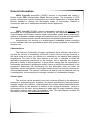
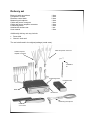
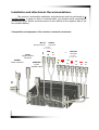
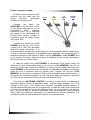
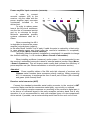
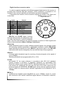
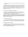
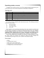
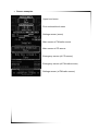
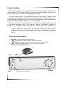
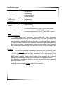
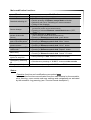
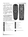
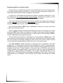
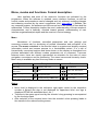
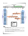
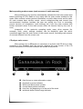
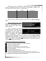
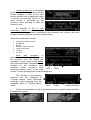
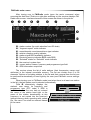
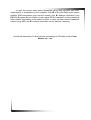
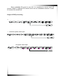
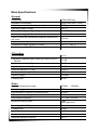
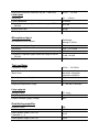
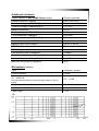
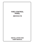
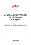
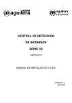
Customizable Digital Device Automobile CD-MP3 receiver USER MANUAL Specifications Certification information Guarantee policy Version 0.96 May 2005 www.СDD.ru ATTENTION! When purchasing: • make sure that the receiver has no mechanical damage and ask for its functional check • make sure that guarantee and tear-off cards specify works number, release date, store stamp, decipherable signature or stamp of the sales person and date of sale. Remember that in case you lose the guarantee card you forfeit your right to guarantee repair • check the receiver’s completeness • check the safety of protective stamp on the receiver’s frame and make sure that Personal Unblocking Code (PUK-code) indicated on the back-page of the “User manual” is not broken After repair: • Ask for the receiver’s functional check being performed in your presence • Check the availability of protective stamp on the receiver’s frame, ripping of the tear-off card and the mark of the fulfilled works indicated on the back of the guarantee card Carefully study the content of this User Manual, this will allow to reduce the time of the receiver’s parameters installation and tuning and to avoid errors that can damage the receiver and other components of the audiosystem. To avoid the receiver’s breakdown, its installation into an automobile should be performed in a specialized positioning center or workshop. The receiver shall be supplied by the automobile’s board net with the nominal voltage of 14.4V and the car body’s minus sign. The receiver is meant for use in GOST 15150 conditions, in category 2.1 moderately cold climate, in this regard the lower operating air temperature shall not be lower than ○ ○ ○ +1 C, transportation and storage temperature shall be from -30 C to +60 C. General information URAL ConceRt automobile CD-MP3 receiver is developed and made in Russia under CDD (Customizable Digital Device) project. The purposes of CDD project included and include development and market introduction of original digital devices enabled to change the stereotyped image of functionality, method of construction and use of widespread domestic electric appliances. Concept URAL ConceRt CD-MP3 receiver (hereinafter referred to as receiver) was developed as a programmable device not limited by the traditional framework of rough hardware functionality, oriented toward its possible update and broadening by means of embedded software change and toward the user’s possible soft adjustment of numerous behavioral and acoustic parameters and possible personification. Architecturally, the receiver is a multiprocessor embedded system controlled by the multitask real time operational system with special peripheral of automobile acoustic use. Characteristics The receiver’s functionality is largely represented by its software, that is why to say that the receiver is excessively functional or does not have enough functions is the same thing as to form you attitude to a computer by its installed and operating programmes. The task of this User Manual is not only to describe in detail the application programme performed by the receiver, but to describe the receiver’s potential in terms of this programme. It goes without saying that the description of functionality (performed in programme terms) cannot go without the description of the programme performing this functionality, but this description shall not make the impression on the user that the receiver has limited functions or that the functions are strictly predetermined. The receiver’s software (as distinct from its hardware) and, as a consequence, its functionality will undergo a number of considerable changes. Version types The receiver can be supplied in two main versions differed by the absence or presence of embedded power amplifiers. All version specifications (excluding power amplifier section) are identical, constructionally the version without embedded power amplifiers differs by the absence of radiator at the receiver’s backplate (and as a consequence, by the size), by the absence of cable with PA output connector and by the specific value of main fuse (3A instead of 15A). This User Manual contains the description of version with embedded amplifiers. Basic functions Audio • • • • • • • • 24-bit DAP, 24-bit ADC Line input (stereo) + microphone input (stereo) 6 independently controlled line inputs (7V) + subbuffer input 6 power amplifier channels (max: 4х45 W + 2х35 W) 6 DSP-treated independent channels 6 independent high-accuracy hold-up channels Embedded 3-lane crossover (cut-off rate 12/24 dB/oct) Embedded graphic one-third-octave (30 lanes) or equivalent parametric equalizer Independent stereo base control for three pairs of stereo channels Embedded test and measuring signals generator • • CD-section • • • • • Media: СD-DA, CD(-R,-RW) File control systems: multisession ISO9660/Joliet, UDFS* Compression formats: (AD)PCM, WAV, MP3, Vorbis*, FLAC* СD-Text (CD-DA), Tags (for compressed formats) Electronic antishock (including that for CD-DA) FM-radio • • • • • • Digital programme and hardware radio signal processing FM(stereo) and VHF (stereo) bands FM synthesizer’s frequency spacing 10 kHz RDS and Radiotext* system support Random station choice option Fragment repeat mode (without information loss) User interface • • • • • • Graphic VFD-display Tentative one-button control" (encoder) Multimedia animation menu Multilanguage font and code support (UNICODE-16) Voice informer Distance control desk (widespread desk support) Attachment interfaces • • Embedded automobile diagnose interface (Electronic document management system) MegaBUS fast-speed interface (5Mbps): o ATAPI BOX*: ATA-accumulator support (HDD, ATAPI-CD/DVD) o Computer connection o Transmitter connection Software support and update Embedded software update performed by the user Reprogrammable menu, options, animation Development engineer feedback (development engineer’s Internet site) Additional service options On-board computer mode work Nonvolatile memory of all settings Embedded real time clock Calendar, alarm-clock, timer/time check Notebook, Dictaphone, games* Safety Power saving timeouts "Hands Free"* option Motion parameters * monitoring Many-level anti-thief protection system Delivery set Base unit with escutcheon Faceplate in a case Distance control desk Measuring microphone Cable and power connector Cable and power amplifier connector Positioning frame Attachment sections set User manual 1 item 1 item 2 item 1 item 1 item 1 item 1 item 1 set 1 item Additionally delivery set may include: • • Demo disk Owner’s club card The set is delivered in the original package (metal case). Cable and power connector Cable and power amplifier connector Installation kit Positioning frame Faceplate case Base unit Escutcheon Faceplate Measuring microphone Distance control desks Installation and attachment. Recommendations. The receiver’s automobile installation and attachment shall be performed by a qualified expert. In case you have no relevant skills, you should consult a specialized positioning center. Before commencement of work switch off the negative side of the accumulator battery. Composition and purpose of the receiver’s external connectors. MIC IN Microphone input LINE IN Line inputs • Line inputs Red Wh 1 Wh 2 4 Wh Red 5 6 SUB Red 3 Line tagging Cable length 15сm Yel SPEAKER Power amplifier inputs LINE OUT L Wh 15A POWER Power connector Red R DATA Digital interface connector MIC Line tagging Cable length 30сm Safety cutoff ANT Aerial connector Power connector (POWER) In order to connect power to the receiver, use the cable with the power connector counterpart included in the delivery set. GROUND Black +12V POWER Yellow +12V MEMORY Red ANT/PAMP CONTROL Blue Connect the black line (GROUND) to the car body in one of the places provided for by its construction. When choosing connection point, try to minimize the length of the connecting line. Provide safe electric contact in connection joints for major current flow (up to 15A). Connect the yellow line (+12V POWER) with the car +12V circuit (current up to 15A) thus providing safe and quality connection. It is recommended to connect this circuit directly to the accumulator battery positive side. In order to optimize operation of embedded power amplifiers, use connecting line of increased section for the receiver’s power circuits (GROUND и +12V POWER) and try to minimize its length. When the receiver is switched off, the current consumed in this circuit does not exceed 10mA. In case the yellow line (+12V POWER) is connected to the power circuit not switched off from accumulator battery, the red line (+12V MEMORY) can be not switched (in this case it should be isolated). In case by some reason the yellow line (+12V POWER) is connected to the circuit with the switched-off voltage (for example, when the key is removed from the ignition lock), connect the red line (+12V MEMORY) to the circuit not switched off from the automobile accumulator battery. It is required for consistent operation of real time clock when the receiver is switched off. The current consumed in the circuit does not exceed 10mA. The blue line (ANT/PAMP CONTROL) is used to control power or switching of additional devices (active or automatic aerial, external power amplifier, etc.). The voltage of this input (+12V, filtered from powerful unwanted signals) appears in several seconds after the receiver is switched on. In case the total current consumed in this circuit exceeds 0,7A, use an additional relay (is not included in the delivery set). The circuit has an electrical protection from exceeding the current-carrying rating. When the protection responses (it is determined by indirect indicators), it is required to switch off and to restart the receiver in several seconds. Power amplifier input connector (SPEAKER) In order to connect acoustic systems (AS) to the receiver, use the cable with the power amplifier input connector counterpart included in the delivery set. In order to reduce power loss at the AS circuit resistance, use the line of increased section and try to minimize its length. Minimum permissible acoustic systems resistance shall be 4 Ohms. 1 2 3 4 gray white blue violet 5 brown 6 green When connecting the AS it is desirable to observe the power amplifier’s signal phase (polarity), to this effect each “holdout” line of each 6 cable line pairs is marked by a black strip. In case phasing errors are found (after the receiver’s installation is completed), correct the phase (Menu->Sound->Invertor). Optionally (after the system’s installation is completed) it is possible to change the channel switching, i. e. its numbers (Menu->Sound->Commutator). When installing multilane (crossover) audio system, it is recommended to use the receiver’s embedded crossover instead of external passive junction filters (Menu>Sound->Crossover). This will improve audio quality and increase the efficiency of power amplifier use (see Recommendations on acoustic performance section). Attention! Power amplifier cables of the fifth and sixth channels of receivers with C00xxxx serial numbers have erroneous polarity marking. When connecting AS, it is necessary to exchange the lines in each pair of brown (fifth channel) and green (sixth channel) lines. Receiver aerial connector (ANT) Connect the standard automobile aerial cable connector to the receiver’s ANT connector. Make sure that the connectors make tightly, are not dirty or oxidized. In spite of taking complex measures on screening of the receiver’s digital part, it is the source of unwanted signal in the radio reception exclusive band, that is why operation it is not recommended to work with standard types of inter-compartment active aerials. If possible, use an external whip aerial fixed on the car’s roof or boot. Digital interface connector (DATA) In order to organize interfaces with different external digital devices the receiver is provided with 8-contact DIN-type connector. DATA connector’s counterpart in not included in the receiver’s delivery set and shall be purchased separately. Composition and location of the connector’s signals are shown in the figure and DATA connector (socket) in the chart: output-side view # 1 2 3 4 5 6 7 8 - Signal RELAY2 GND K-LINE MEGA_A MEGA_B RELAY1 RELAY3 GNDS SHIELD Purpose Relay input 2 Signal ground K-Line input/output MegaBUS tire MegaBUS tire Relay input 1 Relay input 3 Screening ground Screening ground 2 5 4 1 3 8 6 7 SHIELD RELAYx and K-LINE signal functions shall be determined by the programme and can differ significantly in various installation types. The user shall determine the specific purpose of function of these signals and some of their parameters (Menu->Settings->Interfaces*). RELAY1(2) digital (threshold) inputs for slowly changing external signals. Are generally meant for connecting contact transmitters or automobile automatics circuits. RELAY1(2) signal switching thresholds are fixed, RELAY1 input active state is low, RELAY2 input active state can be changed by the user with the help of the programme. RELAY3 universal digital (threshold) input for receiving of external signals at the speed of up to 100KBps. Switching thresholds are programmable (5V or 2,5V). K-LINE two-headed “K” tire (open collector) in accordance with ISO 9141 standard. Primary purpose is emulation of diagnostic equipment for automobiles with Electronic engine control system (EECS). Switching thresholds (5V or 2,5V) and load resistor are installed by the user with the help of the menu. Apart from the primary purpose (K-LINE EECS), K-LINE signal can be used as a general purpose input or output for external device interface organization at the speeds of up to 100KBps. MEGA_x specialized two-headed speed MegaBUS tire (up to 10MBps) meant for control and connection with remote intellectual digital devices of information collection, storage and processing. The number of tire devices depends on their purpose and can reach ten. All interface signals are protected from back voltage and (direct) voltage overloading, nevertheless, when connecting, it is required to observe common safety precautions (to check the signals compatibility according to voltages and currents levels, commutations shall be performed when the power of all the devices is switched off, to avoid signal inter-bridging, on the ground or power circuit). It is recommended to connect external signals to the DATA connector in one of Authorized Service Centers. Line output connectors (LINE-OUTx and SUB-OUT) In order to connect external power amplifiers, the receiver is provided with six high-voltage line outputs and subbuffer amplifier output (RCA connector type). Output stages of line output signals are made on speed low-noise operating devices with low output resistance and short circuit protection. In order to obtain maximum Signal/Noise ratio of the audio system that uses external power amplifiers, it is required to coordinate their responsitivity with the voltage of the receiver’s line outputs with the help of external power amplifier GAIN regulator. In some cases the coordination may require installation of 2:1 resistance divider at the power amplifier output. Line input connectors (LINE-IN) In order to connect external audio signal sources, the receiver is provided with line input RCA-connectors (stereo input). Responsitivity of line inputs (the level of digital amplification) can be controlled by the programme (Menu->Settings->Input). Microphone input connector (MIC-IN) MIC-IN connector (stereo 3.5mm Phone Plug) is meant for connection of measuring stereo microphone included in the delivery set. In order to reduce noise and phone that can appear in some mixing modes, the microphone amplifier can be switched off (Menu->Settings->Amplifiers). Operating modes, screens In operation the receiver can be in one of the modes generally determined by the current data source and internal programme and hardware configuration. Operating mode: Mode Data source 1 2 3 4 5 6 7 FM CD LIN AUX* LAB ECU BLK FM-radio embedded CD-drive line input/microphone external source (for example, HDD-accumulator) generator/measurement on-board computer block signaling (mode without data source) 8 ERR accident condition (hardware or software breakdown) 1-4 modes are basic (operation with audio data sources). The following combined modes are also possible: 9. 10. 11. 12. FM + LIN (+ECU) CD +LIN (+ ECU) AUX + LIN (+ ECU) LIN + ECU Mode transition can be performed according to the user’s signals (or actions) and can also be the consequence of definite (including accidental) events. The examples of mode changing conditions are: preset time oncoming, timeout expiration, CD-disk loading/unloading, faceplate removal, key turn in the ignition lock, switching off or malfunction of the external data source, change of parameter controlled by the onboard computer, repeated erroneous password entry, hardware or software failure. In any mode (besides BLK and ERR)in the process of data processing or under the user’s control, the receiver can change its states and these changes are accompanied by showing relevant user screens at the faceplate display. Screen types: • • • • • Menu Settings screen (menu) Main screen (of the data source) Emergency screen (of the data source) Settings screen (of the data source) • Screen examples Upper level menu First enclosed level menu Settings screen (menu) Main screen of FM-radio source Main screen of CD source Emergency screen (of CD source) Emergency screen (of FM-radio source) Settings screen (of FM-radio source) Control bodies The receiver provides full and easy control of all functions with a minimal set of control bodies. The size and location of control bodies are carefully planned and it allows to use them “at random” not straggling from driving. For each control body or its combination there exist a number of simple, easily rememberable modulations providing optimal access to all the receiver’s functions in all its operating state and modes. The most useful and usable control operations are performed by the simplest modifications – short pressings. The receiver’s control is mainly intuitive, i. e. any time a definite modification lead to the most desirable result. The receiver’s definite modification response is contextual, i. e. it depends on the operating mode and the current state in this mode. In order to simplify the random control, some important events (source change, input in operating nested menu, etc.) are accompanied by an audio signal (BEEP) of the dynamic embedded in the receiver (the BEEP volume does not depend on the volume of the whole system). Control bodies composition: • • • • • Encoder (twist handle with an imbedded button) “ESC” button (big key located at the left side of the faceplate) “EJECT” button (disk eject button located at the inner side of the faceplate) “REL” buttons (faceplate changeover button, mechanical function) Distance control desk buttons REL ESC EJECT DC infrared receiver window Encoder Modification types: Encoder “ESC” button "EJECT " buttons • DC desk buttons Combinations • turn • short pressing • long pressing • pressing and turn • double pressing • short pressing • long pressing • double pressing short pressing • • single pressing double pressing • • • simultaneous pressing of “ESC” button and encoder simultaneous pressing of "EJECT" button and encoder simultaneous pressing of "EJECT" and “ESC” buttons Notes: Turn (of the encoder): This is the most commonly used modification (main parameter regulations are performed by the encoder’s turn). For easy regulations the encoder’s handle has a big diameter and is supplied with a number of inside and outside lugs allowing to make a turn with one or several fingers. Besides, in order to reduce regulation time (when the ranges of tunable parameters are large), the encoder’s responsiveness increases on condition that it actively and continuously rotates during a definite period of time (thus, for example, the accelerator switches on). Pressing: The receiver responds to pressings (and turns with a pressing) when the button is released. Any pressing is considered short if it does not exceed ~1,5 sec. Any longer button holdup is considered to be a long pressing. The majority of short pressings and all long pressings are accompanied by a short BEEP signal, besides, shortly before making a long pressing the receiver’s display starts to change its brightness in a smooth and repeated manner. Any pressing is considered double if a pause between two short pressings does not exceed ~1sec. Pressing with a turn is a short pressing on the encoder when the encoder’s handle is turned sideward before release of the encoder. Main modification functions: Function Switching on Standard switching off Source change Switch over to the main screen of the main Source Sound Muting/Unmuting and и CD-mode pause Current time announcement Fragment repeat in FMradio mode Menu entry Deleting of the last symbol in entry line Non-standard (emergency) switching off Emergency disk eject Modification • • • • • • Long pressing on the encoder Simultaneous pressing of “ESC” button and the encoder Double pressing of Distance control desk red button Selection and use of “Switching off” menu command Taking off the faceplate Double pressing of “ESC” button (on the main screen of the current source) • Pressing of relevant Distance control desk buttons (“CD”, “Tuner”,..) • Double pressing of “ESC” button (not on the main screen of the current source) • • • • • • • • • Pressing of Distance control desk green button Short pressing of “ESC” button Pressing of Distance control desk “Mute” button Long pressing of “ESC” button Pressing of Distance control desk “Voice” button Double pressing of the encoder Pressing of Distance control desk “Repeat” button Pressing with a turn (of the encoder) Pressing of Distance control desk central "О" button • Short pressing of “ESC” button (in entry line mode) • Simultaneous pressing of " EJECT " button and the encoder • Simultaneous pressing of " EJECT " and “ESC” buttons Notes: Operative functions and modifications are marked gray. Less operative functions are activated from the main screens by the encoder’s short pressing, more remote and rarer settings and navigations are activated by the encoder’s long pressing (see “Function formal description”). Distance control desks The receiver’s delivery set contains two standard IR-desks with different versions and number of buttons. The receiver supports simultaneous operation of two different distance control desks, the user can use desks of other models and manufacturers, apart from the standard desks (or instead of them). The receiver is compatible with desks using 36...38 KHz carrier frequency and RC-5, NEC or semiNEC modes for transmission. Functions of all buttons of any desk can be set (reset) on the setting screen (Menu->Settings>Distance control desk). By default the standard desk buttons are marked in accordance with the functions most commonly used in the receiver. Functionality of some buttons can insignificantly differ in various modes. Some buttons and their main functions are listed bellow: Power off (red button) Playback mode selection Return to the main screen of the current screen (green button) Album selection Switch over to RM-Radio source Time announcement Switch over to CD source Style selection Show “Clock” screen (trigger) Change of display brightness Sound muting / CD pause (trigger) Navigation through radio stations and tracks Menu entry (the desk’s central button) Recommendation on control modes The encoder is a mechanical regulator and is exposed to wear. Do not apply extra force when working with the encoder, try to use it only when necessary and prefer to control the receiver with the help of distance control desk. In case over 10 seconds passed after the receiver’s standard switching off, it can be switched on only by the encoder’s long pressing, otherwise the receiver can be also switched on by pressing the distance control desk red button. The sound volume (of audio sources and the informer) is regulated by turning the encoder only on the audio sources’ main screens and on the clock screen. On other screens turning of the encoder exercises other functions. Use “double pressing of ESC button” modification in order to turn over to the main screen from any other screen. Sound muting/unmuting functions and CD-player pauses are activated by a short pressing of ESC button and are available in all audio modes and subsidiary screens, except the entry screen of the user text line: on this screen a short pressing of ECS is used for deleting the last symbol of the line. Current time announcement is activated by a long pressing of ESC button. The announcement takes several seconds, during the announcement the display shows the clock screen automatically changed by the current main screen. Sound volume control during time announcement cancels turn over to the main screen. Use “the encoder’s double pressing” to repeat the last 10 seconds of the radio programme. To compensate time loss when playback is rolled 10 seconds back, playback speed is increased (and then is slowly reduced) till synchronization with the programme real time. ‘R sign located in the upper line of FM-Radio source main screen indicates the repeat mode of the receiver. After time lag compensation is completed (in approximately 40 seconds), the receiver automatically logs off the repeat mode. The repeat mode is interrupted by pressing of any button (in this case information loss is inevitable). Sound volume control does not interrupt the repeat mode. Menu, modes and functions. Formal description. User interface and most of the receiver’s functions are activated by the programme. When the software is updated, some interface functions, as well as control modes and procedures can be changed and (or) widened, including changes and widening occurred by the users’ suggestions (see. www.cdd.ru ). Besides, like any computer system, the software can have errors and in the course of time shall be modernized. Further description implies the user’s understanding of these receiver’s characteristics and is basically oriented toward general understanding of user interface organizational principles and the receiver’s control strategy. Menu Abundance of functions, controlled parameters and user settings and numerous screens ask for structuring of printed information and unification of its access. The menu embedded in the receiver helps to organize and simplify required information control and access process to a considerable extent. It is a set of hierarchically connected sections and items shown on the display as formalized icon pictures associated with different modes, parameter set or command. Turnovers between menu items are visually represented as animation for the sake of menu navigation convenience and its positioning. The menu has several hierarchy levels. Menu entry is available any time from any mode or screen. Operation Faceplate DC desk Menu entry pressing with a turn central button Traverse through one-level menu items turn “right” and “left” buttons short pressing (down) long pressing (up) “up” and “down” buttons double pressing of ESC button green button Traverse through menu levels Menu exit to the main screen of the current source ESC Notes: • • • Menu level is displayed in the indicator’s right upper corner by the respective number of signs (the sign is not displayed for upper/zero level, one sign is displayed for the first embedded level, etc.) Traverse to the menu upper level by the encoder’s long pressing is accompanied by the level sign flash. After selection of the required menu item the encoder’s short pressing leads to the transfer to the relevant setting screen Menu structure S e l e c t o r S o u r c e s Settings EDMS Switching off Clock Player Radio Line input Sound Selector Tags Selector Tuner Animation Style Mixer Delays Stereo base Entry mode Sources Line input Sound Volume Equalizer Amplifiers Settings Initial Maximum Increase Stereo base Informer Inverter Entry Filters Screen Frequency Crossover Timeouts Balance DAC Password Reset Crossover Commutator DC desk Info Sound Descriptive data: Encoder’s turn Generator Monitor Menu item New SW Short pressing Setting screen Notes : “New Software” menu item is available only after scanning of the disc containing file(s) with software update. Source composition (and availability of respective items in “Selector” upper-level menu) depends on the user settings (Menu->Sound-> Sources). “Sound” level menu items composition is displayed for “Crossover system” acoustic setting configuration. In other configurations this composition can insignificantly differ (see Picture “Stages of DSP-processing”). S o u n d Volume Mixer Equal. type. Acoustics S e t t i n g s CD/Radio Main operating mode screens (main screens of audio sources) After switching on the receiver automatically chooses the last main mode used before switching off (CD, Radio or Line input) with the main screen suitable for this mode. Main screens contain general information on audio data source and its state. All main screens have volume control, sound muting/unmuting and current time announcement functions, besides, the user can quickly turn over to secondary source screens (of navigations, quick settings, etc.) from the main screens with further automatic return to the main screen (after the timeout fixed by the user is over). Irrespective of the receiver’s operating mode, many other screens (for example, clock, menu, settings screens) can be displayed upon the user’s commands apart from the main screen of the current source, excluding main screens of sources different from the current one. CD-player main screen After turning over to CD mode (in case there is a dick in the CD-drive or after scanning of the reloaded disk) the receiver displays the main screen of the CD source. Elements of CD screen interface are shown in the picture: n s o p q r n - field for text or video information output o - playback or pause indicator p - album and album track number q - current track position indicator r - time from the beginning or to the end of the track s - antishock buffer critical range indicator Playback of audio composition is accompanied by the output (vertical scrolling) of CD-Text content (for audio disks) or tags (ID3v1 or ID3v2) to the information field of the main screen. The tags consist of: Track name Singer Album name Year File name Folder name Comments Full set z z z z z z z Reduced set z z z Selection of full or reduced tag set is made by the user (Menu->Settings-> Tags). When controlling the volume, information field of the main screen displays a semi-tranparent scale of relative volume and a digital volume value in decibels. After the encoder’s short pressing, the bottom of the main screen displays mininavigation menu consisting of a set of pseudo-buttons with conventional presentations of their functions. The encoder’s turn and a short pressing select and perform the selected function. Mininavigation menu is removed from the main screen after the timeout is over (see Menu->Settings>Timeouts->Track_selection) or when the function indicator (brightening of the buttons) is moved over the screen’s left border. Moving of the indicator over the screen’s right border or the encoder’s long pressing is equivalent to pressing of “Open disk navigation” pseudo-button. Purpose of mininavigation menu pseudo-buttons: Turnover to the previous album or 10 tracks backward Turnover to the previous track Turnover to the next track Turnover to the next album or 10 tracks forward Open disk navigation (through tracks and (or) albums) In-track positioning File or track information output Playback sequence selection (6 variants) Track time-taking method selection: “from the beginning” or “to the end” Moving of the indicator along the pseudo-buttons is accompanied by the BEEP sound signal and prompt output on the information field. In-track positioning is performed by the encoder’s turning, in this case the screen displays a scale of the track relative position and a digital time value in minutes and seconds. Return to the main screen is performed by the encoder’s short pressing or after the timeout is over. An example of file or track information screen is shown in the picture. Information parameter is selected by the encoder’s turn, return to the main screen is performed by the encoder’s short pressing. Information parameters contain: • • • • • • • Coding/compressing method Sample rate Bit rate Number of audio channels Length of sounding File type File size Open disk navigation is performed in the navigation screen by the encoder’s turn. By default the navigation covers tracks of the whole disc (vertical scrolling). Playback track is selected by the encoder’s short pressing, further encoder’s short Track pressing activates return to the main screen. Current (playing) track is marked bright red. The encoder’s long pressing switches over the navigation to “Through albums” mode (horizontal scrolling), a short pressing turns the navigation back to “Through tracks” mode. Track Album Album Number of albums Control and navigation of video clip playback have no specific characteristics. Examples of screens: FM-Radio main screen After turning over to FM-Radio mode (upon the user’s command, when removing the disk from CD-drive or right after switching on) the receiver displays FMRadio main screen. Interface elements of this screen are shown in the picture: n o p q r s t u v w n - station number (for quick selection from DC desk) o - “fragment repeat” mode indicator p - mono/despotic mono/stereo/stereo type indicator q - relative reception quality indicator r - station signal RDS-availability indicator s - Receiving country indicator (ECC-code RDS) t - “Selected” station or “Selected” mode indicator u - the receiver’s system time v - current station’s name, frequency and programme type field w - RDS-information output line The receiver stores the list of radio stations (their frequencies, names and attributes) in the internal nonvolatile memory. The list can contain from 0 to 99 elements. Options of including stations in the list and their removal from the list can be performed automatically or hand tight by the user (see FM-Radio source settings screen). When turning over to FM-Radio mode (and when there is at least one station in the list), the last station used is selected automatically. Field v alternatively displays the station’s user name, its frequency and programme type (PTY code) if RDS is available. In case the user has not entered the name of the station hand tight or the name of the station broadcasting at this frequency is not copied into the receiver’s internal memory when operating with update file, “No name” line shall be entered instead of the name. In case the current radio station broadcasts using RDS standard and RDSsignal quality is acceptable for the reception, field r of the FM-Radio main screen displays RDS-transmission sign and the screen’s line w displays information from PS field (Program Service Name) of radio signal RDS-component. In most cases this field contains information on the station’s name. In case the radio station broadcasts without using RDS, line w contains information on the stations’ frequency. Consult the description of other screens and settings in FM-radio mode in User Manual ver. 1.xx Consult the description of other main screens and settings screens in User Manual ver. 1.xx Recommendations on the acoustic setting configuration The task of achieving high-quality passenger compartment sounding is a complex task requiring a creative approach to its solution. End result is influenced not only by the leading device, but also by the number and type of acoustic systems (AS), their location, compartment characteristics, audio components power supply and connection system, sounding quality evaluation procedure (usually subjective) and the ability to harmonize all these elements. It is impossible to formulate identical rules, to give “a recipe” of an admittedly winning solution. This section contains several recommendations on audio system installing on Ural ConceRt receiver basis. They do not claim to be complete, but in general, they are suitable for the most frequently used conditions. The receiver has 6 independent logical sound processing channels that correspond to 6 physical output channels: 6 line outputs (LINE OUT1…LINE OUT6) and 6 power amplifier (PA) outputs. Line and PA outputs have a strict one-to-one correspondence, while their correspondence to the logical processing channels can be measured liberally (Menu->Sound->Commutator). All six physical channels are universal and identical, apart from the fact that the fifth and the sixth channels use power amplifiers of lower maximum power. The subsidiary line output (SUB OUT) is not independent, it is formed on the apparatus basis as a filtered (2-category Batterwort filter with 60Hz cutoff frequency) and accelerated sum of the first and the second channels. It is important to understand that the receiver’s channels have no strict purposes (like front, back, LF, MF, HF, Subwoofer), any time it is required to make an individual decision on connecting a definite power amplifier to a specific physical channel taking into consideration a number of factors. Thus, for example, connecting the subwoofer to LINE OUT1…6 will add more flexibility to its setting than in the case it is connected to SUB OUT output, AS HF shall be connected to 5 and 6 channel of PA, while more powerful 1…4 PA channels shall be used for LF and MF AS. The receiver is supported by several acoustic setting types determined by their purpose and processing states of sound processing logical channels (see Stages of DSP-processing). Selection of acoustic setting type is made in the menu (Menu>Settings-> Acoustics). • “6 independent channels”. This type of acoustic setting differs by the identity of all 6 sound processing logical channels, equalizer independent for all 6 channels and the absence of the crossover. Such configuration is generally oriented toward the use of broad-line AS. The examples are: standard automobile AS, adding of AS to the standard ones, installation of AS in standard places, minibus equipment, etc. • “5.1 System”. This acoustic setting supports 5 broad-line channels (two front, two back and central channels) and the subwoofer channel. The central channel represents a monophonic version of the original signal and together with back and front channels is equipped with an independent equalizer. In this configuration the subwoofer channel has cutoff frequency control. The examples of the use of “5.1 System” setting are: broad-line back and front (AS standard installation) plus subwoofer; use of the receiver together with an automobile video; realization of the central channel for “raising” of the sound state. • “Crossover system”. As a rule, this acoustic setting allows to achieve maximum sound quality of the audio system by using the AS meant for the playback of individual audio range segments. With the help of the embedded crossover the original signal can be divided into three frequency components (LF, MF, HF), each of which is determined independently by filter types and frequencies settings. The examples of this acoustic setting type use are: 3-line front plus subwoofer (uncontrolled), 2-line front plus subwoofer (controlled), 2line front plus back. • With the advancement of software, it is possible to realize other types of acoustic setting. It is recommended to use embedded crossover (instead of external passive junction filters), especially in case the AS is supplied by internal PA. This will allow to increase significantly the total sound volume and its quality will be preserved because of the more efficient use of PA each of which will amplify an individual part of the frequency audio range. Installation of 3-line system without using any external amplifiers can be the most efficient (and economic) one. Apart from characteristics of individual AS, it is desirable to take into consideration charts of music signal power distribution along the spectrum (DIN, IEC) when selecting crossover separation frequencies for power equalizing of all frequency channels. In case it is necessary to use both the receiver’s internal crossover and external passive crossover, it is recommended to use the external crossover for separation of more high-frequency lines. Such passive crossover will provide higher sound quality and have smaller size and cost. Notes: AS selection must by accompanied by a careful analysis of their characteristics (displayable frequency line, responsiveness, nominal power) and places of their possible installation (taking into consideration reflections, directivity and acoustic insulation). In order to minimize possible parasitic actions when using SUB OUT signal, it is recommended to set delays for the first and the second channels, so that their difference (in centimeters) did not exceed the difference between the distance from the subwoofer’s loud-speaker to the listening point and the distance from the first or the second loud-speaker (the most remote from the listening point) to the listening point. Coax AS do not require equaling of delays between their comprising dynamic heads, so in order to connect a coax AS, it is recommended to use one processing logical channel by releasing logical channels for other AS (for example for the subwoofer). When embedded PA work for coax AS, it is expedient to connect each AS dynamic head to a separate PA channel and to use an embedded crossover in order to increase the sound level. Stages of DSP-processing • • Crossover system, stereo input 5.1 System, stereo input Software Updating As many other devices operating under software control the receiver enables renovation of the internal control programme and data processed by this programme. The process of receiver software updating is performed by transfer of the required software code or data from the file stored on the CD to the receiver’s non-volatile memory. To prepare the updating disk it is required to record the updating file WITH a music track/tracks in one of the formats supported by the receiver on a CD-R or CDRW. Updating files are available on home page of www.cdd.ru . In most cases updating implies changing of the internal version of the receiver software for a fresher one (major version with a bigger sequence number). In this case when starting up a disk with the update (with the set Autostart option for CD, see Menu->Settings->Sources) the updating procedure starts automatically. The receiver allows changing the version for an earlier one (with a smaller sequence number), in this case ‘update’ should be started manually. After updating process startup the user is offered to select one of the several updating options (interface language, updating of software or a list of broadcasting stations, city of station broadcasting, etc.), after option selection updating process is accompanied with displaying information on updating progress. Notes: • It is not recommended to use “high” disk recording speeds (higher than the 8th for CD-RW and higher than the 16th for CD-R) • It is not recommended to record several different software versions to one disk as well as to record multisessional disk with software • It is not recommended to replace the current software version for an earlier version thereof • Should updating not start automatically for any reason, manual disk starting is possible after its scanning (Menu-> Settings->New Software) • Information on changes introduced into a regular update version is available on one of the web sites of the engineering company at: https://uralconcert.nirokr.ru/beta/ Attention! Do not interfere with software updating process till its automatic completion! Password protection To prevent stealing of the front panel an identity check for the serial numbers of the base unit and the front panel is performed. In case these serial numbers are not identical the receiver displays a respective message (accompanied with a warning BEEP signal) and switches off in some seconds thus making its operation impossible. Besides protection against front panel stealing the receiver has individual password protection against stealing of the base unit that can be activated at user’s request. Objectives and Strategy of Password Protection Prevention of unauthorized receiver usage: If there’s an attempt to switch on the receiver after its physical disconnection from the vehicle board system the user is required to enter the password. Limitation of access to critical receiver settings: Changing of some adjustable parameters can result in damaging of speakers or other audio system components. As a rule these parameters are of global character that characterize the audio system as a whole and are changed rarely (e.g. switchboard, crossover settings, etc.). To change any of these parameters the user is required to enter a password. Password protection on and off On default (factory setting) the receiver is supplied with protection switched off. Switching on (activation) and off as well as password change is done by selecting Menu-> Settings->Password. In case protection is activated for the first time it is required to select a ‘set a password’ option after entering the specified menu option. The user is offered to enter a password and then confirm it with a reentry. The password is entered like any other user’s text string, but the entered symbols are displayed with “*” symbols. The password can be of any length from 0 to 127 symbols. Password protection is activated after correct password conformation. The entered password remains active till its changing with a “change password” option or till its positive deletion by using a Personal Unlocking Key or PUK-code (see the last page of the User’s Manual). Activation or deactivation of password protection DOESN’T AFFECT the password itself. To deactivate protection it is required to select a “Deactivate Protection” option and enter the password set while protection activation. To reactivate protection it is required to select an “Activate protection” option and enter a password using “Set a password” and “Change a password” options. To change the password it is required to select a “Change password” option, enter a current password, then a new password and its confirmation. Password query conditions Password entering is required for any changes in password protection system (its activation, deactivation, password changing). While password protection is activated password entering is required in the case specified below: • Once per working session (from the receiver switching on to its switching off) while entering one of the screens: Settings->Clearing Settings ->Sources Settings ->Acoustics Settings ->Volume->Initial/Maximum/Increasing/Informer Sound->Style (while style adding, deleting, or renaming) Sound ->Balance Sound->Delay Sound->Stereobase Sound->Switchboard Sound->Invertor Sound -> Equalizer type Sound->Equalizer Sound->Subwoofer Sound->Crossover->Filters/Frequencies Sound -> DAC • After an attempt to use the receiver after its physical disconnection from the vehicle board system (de-energizing) • After switching on the receiver in case an incorrect password was entered during the previous work session while entering any protected screens or a screen controlling password protection Receiver Blocking In case of triple (during one working session) entering of an incorrect password the receiver displays a warning message and switches off entering a lock mode (BLK). To unblock the receiver it is required to enter the PUK-code. Password protection is deactivated and the password is deleted (initial state) after unlocking. If the password is lost In case the password is lost enter any three passwords (e.g. by using Menu-> Settings->Password, and “Change Password” option). Enter the PUK-code after the receiver passes to the lock mode. Protection will be deactivated and the password will be deleted. Main Specifications General Dimensions 178х50х200 mm Installation dimensions 182х53х182 mm (1-DIN) Weight (base unit with the front panel) 1750 g Operating supply voltage 14.4 V Permissible supply voltage range 8 …18 V Maximum energy input 250 W Useful current with distribution amplifiers switched off, not more 550 mA Useful current in operation 10 mA Temperature range (except СD mode) -30 0С … +40 0С Temperature range (CD mode) +1 0С … +40 0С CD-section Spindle speed 1x, 2x Frequency-response ripple within the range of 20 Hz … 20 KHz 0.5 dB Signal-noise ratio (-1 dB) 93 dB Signal-noise ratio (-10 dB) 98 dB Nonlinear distortion (-1 dB) 0.002 % Nonlinear distortion (-10 dB) 0.001 % Dynamic range 118 dBA Coupling loss 80 dB Radio Received frequencies range 65 MHz … 108 MHz Modulation type FDM Discreteness of frequency synthesizer grid 10 KHz AD converter sampling rate 160 MHz Intermediate frequency 10.7 MHz, 200 KHz Stereo decoding system Polar, with a pilot-tone Sensitivity (26 dB S/N), not worse 2 µV Coupling loss 42 dB Signal-noise ratio (mono) 60 dB Nonlinear distortion (mono) 0.05 % Nonlinear distortion (stereo) 0.4 % Amplitude-frequency response (as per -3 dB level) 40 Hz … 16 KHz Line input Sensitivity 0,1 …1 Vrms Feed impedance 47 kOhm Frequency-response ripple within the range of 20 Hz … 20 KHz ±0.5 dB Signal-noise ratio 90 dB Coupling loss 80 dB Microphone input Microphone power system Combined, through 3 kOhm Microphone supply voltage 5V Sensitivity 0.02 …0.1 Vrms Feed impedance 1.5 kOhm Frequency-response ripple within the range of 20 Hz … 20 KHz -3 dB; +0.5dB Signal-noise ratio 90 dB Test oscillator Frequency range 10 Hz … 20.5 KHz Wave form sinus, semi sinus, sawtooth, triangular, meander waveform Sinus frequency setting discreteness 1 Hz Signal length 16 bit Amplitude adjustment range 0…-90 dB (1 dB step) Line outputs Voltage output 2.1 Vrms Output impedance below 1 Ohm Output cascade supply voltage ±8 V Distributing amplifier Amplifier class Load resistance, not less AB 4 Ohm Rated power output (THD 1%) Channels 1 – 4 21 W Rated power output (THD 1%) 19 W Channels 5, 6 Constraint level (FS) -1.5 dB Additional interfaces Output capacity of ANT/PAMP Control output 700 mA, protected Onboard computer interface K-line (ISO 9141) Threshold voltage of RELAY1(2) input 1.5 V Threshold voltage of RELAY3 input 5 V / 2.5 V RELAY3 hysteresis 450 mV Feed impedance of RELAY1(2), not less 2 kOhm Feed impedance of RELAY3 100 kOhm Maximum frequency of RELAY1(2) 5 KHz Maximum frequency of RELAY3 100 KHz RELAY1 open input condition Pull-up 47 kOhm RELAY2 open input condition Pull-up / -down 47kOhm RELAY3 open input condition Not determined Data signalling rate of MegaBUS 10 MBps Communication medium of MegaBUS Twisted pair in a screen Number of devices on MegaBUS Up to 10 Maximum link length of MegaBUS 30 m Microphone (stereo) Type condenser, electret Direction pattern Circular Frequency-response ripple within the range of 30…18000 Hz -0.5…+3 dB (see the Standard Frequency-response ripple diagram in the Fig. below) Sensitivity (0 db = 1 V/µbar) -65 dB Impedance on 1 KHz frequency 1 kOhm Cable length 1.6 m dB Hz Certification Information URAL ConceRt CD-MP3 receiver complies with TU 6582-039-53906226-2004 for multimedia stereophonic car systems, models URAL CONCERT CDD/ -01/ -02/ -03. URAL ConceRt CD-MP3 receiver is certified according to GOST R Certification System of Gosstandart of Russia. Conformity Certificate No. РОСС RU.ME68.H00963, issued on 12 April 2005. Warranty This warranty shall cover only products officially supplied by URAL PLUS LLC. URAL PLUS LLC guarantees general operation capability of the product as well as its components and units within the warranty periods specified herein. Warranty periods shall start from the date of sale provided that the product storage period before sale was not more than two years. Warranty Periods 1. For all components and units, unless otherwise specified 5 years 2. For components and units with a naturally limited life including: - Laser reader of CD drive - Non-volatile memory elements 2 years 3. For components and units exposed to mechanical wear including: - CD drive mechanism - Mechanism of pulling down and locking of the front panel - Front panel control elements - Remote control panels - Connectors 1 year The warranty period for the product operation capability is generally determined by the minimal warranty period for its components. Product defects revealed within the warranty period shall be eliminated free of charge by the authorized Service Centre subject to conditions specified below. Warranty Service Conditions • This warranty is valid only subject to presentation of a guarantee card completed correctly and legibly. • This warranty is valid on the Russian Federation territory. • This warranty shall not apply if: 1. The receiver serial number has been changed, erased, deleted or illegible 2. The protective label on the receiver is broken 3. The receiver has been modified or repaired by an unauthorized service centre • This warranty shall not cover: 1. Maintenance services 2. Replacement of consumables (including batteries), external parts and accessories 3. Elimination of defects resulting from: − Unintended use of the receiver − Careless receiver handling − Receiver connection and operation with parts and units not approved by the manufacturer as well as connection and operation in violation of the requirements and limitations specified in this manual − Mechanical defects − Noncompliance with storage conditions − Ingress of liquid, foreign objects, insects, animals and their life products inside the receiver − Actions of third parties or acts of God − Defects of the system where the receiver was used − Transportation except for cases when it was performed by an Authorized Service Centre − Receiver operation in entrepreneurial activities and/or for business purposes Note For addresses of Authorized Service Centres please contact official dealers or call the sales and quality centre of AvtoAudioCenter Business Group. To be completed Open sale price of the manufacturer. GUARANTEE CARD To be completed by the manufacturer URAL ConceRt CD-MP3 Car Receiver, Serial Number _______________ Date of manufacture ________________________________________________________ Representative of the manufacturer’s Quality Control Department ______________________ Stamp of the Quality Control Department Legal address and the address to file claims in respect of the product quality: 143960, Moscow Region, Reutov City, Gagarina St., 23 а, URAL PLUS LLC To be completed by the distribution point Date of sale Seller _________________________________________________________ Day, month (in full), year _________________________________________________________ Signature or stamp Stamp of the outlet To be completed by the repair service Put up for warranty service _________________________________ __________________________________________________________________________ Name of the repair service enterprise __________________________________________________________________________ Day, month (in full), year Product warranty number ____________________________________________ MAINTENANCE AND REPAIR REGISTRATION Date Rendered services (maintenance or repair) Work content. Name and type of the replaced part Name and signature To be completed COUPON FOR REPAIR WITHIN THE WARRANTY PERIOD To be completed by the manufacturer URAL ConceRt CD-MP3 Car Receiver, Serial Number _______________ Date of manufacture ________________________________________________________ Representative of the manufacturer’s Quality Control Department ______________________ Stamp of the Quality Control Department Legal address and the address to file claims in respect of the product quality: 143960, Moscow Region, Reutov City, Gagarina St., 23 а, URAL PLUS LLC To be completed by the distribution point Date of sale Seller _________________________________________________________ Day, month (in full), year _________________________________________________________ Signature or stamp Stamp of the outlet Cut here ----------------------------------------------------------------COUNTERFOIL OF WARRANTY REPAIR COUPON Date of withdrawal ___________________________________ Radio repair specialist _____________________________________ Last name To be completed To be completed by the repair service Product warranty number ______________________________________________ Cause of repair. Name and number of replaced component or unit as per the diagram ___________________________________________________________________________ ___________________________________________________________________________ ___________________________________________________________________________ ___________________________________________________________________________ Date of repair _______________________________________________________________ Day, month (in full), year Surname, name and patronymic of the person who performed the repair ___________________________________________________________________________ ___________________________________________________________________________ Stamp of the repair service and city Signature of the product owner confirming the performed repair _____________________ ATTENTION! Personal Unlocking Key is specified here To avoid possible unauthorized usage the receiver passes to the lock mode (BLK) after triple incorrect password entering (during one work session) with activated password protection. Access to the receiver menu and function becomes impossible. To unlock the receiver the personal unlocking key is to be entered (PUK-code) by the user after the respective system inquiry. PUK-code is unique for every product and can’t be changed even by a service centre. PUK-code is entered like any other user’s text string. The personal unlocking key is to be known only to the receiver legal holder. By observing the recommendations below you can protect your receiver from unauthorized usage and possible damage of audio system: • • • • Check the continuity of the protective layer on this page or any signs of its coming unstuck, etc. when buying the receiver Delete this page from the user’s manual and keep it apart from the receiver, outside the car in a place known only to you Don’t show the PUK-code to third persons Keep the PUK-code carefully as to restore it you would have to prove that you are the receiver’s legal holder The personal unlocking key is under the protective layer on this page. To access the code, please, erase the upper holographic layer. Take care not to damage the base. Receiver Serial Number: С00хххх Read this page carefully before erasing the protective layer! Personal Unlocking Key ATTENTION! ________ Personal Unlocking Key is specified here