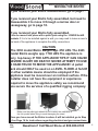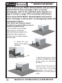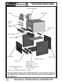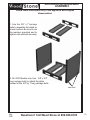
1
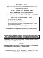
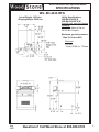
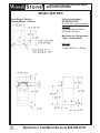
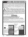
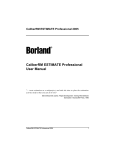
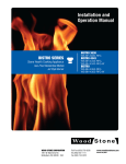
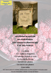
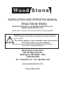
INSTALLATION AND OPERATION MANUAL
Wood Stone Bistro
WS-BH-4343-RFG-(NG or LP), WS-BH-3030-RFG-(NG or LP),
WS-BH-4343-RFG-W-(NG or LP)
Natural Gas or Propane Fueled Stone Hearth Cooking Appliance
!
WARNING: If the information in this manual is not followed exactly,
a fire or explosion may result causing property damage, personal
injury or death.
Do not store gasoline or other flammable vapors and liquids in
the vicinity of this or any other appliance.
Keep the area under and around this appliance free and clear of
any and all combustible materials.
Wood Stone Corporation
1801 W. Bakerview Rd.
Bellingham, WA 98226 - USA
1-800-578-6836
Tel. 1-360-650-1111 Fx.1-360-650-1166
www.woodstonehome.com
Revised May 2007
Wood Stone Bistro
Gas Stone Hearth Cooking Appliance Installation and
Operating Instructions
DO NOT THROW THIS MANUAL AWAY
RETAIN THIS MANUAL FOR FUTURE REFERENCE.
Additional copies of this manual and prompt responses to
service/maintenance questions are available from Wood Stone @ 800-578-6836.
WHAT TO DO IF YOU SMELL GAS
-Do not try to light any appliance.
-Do not touch any electrical switch.
-Do not use any phone in your building.
-Immediately call your gas supplier from a neighbor's phone. Follow
the gas supplier's instructions.
-If you cannot reach your gas supplier, call the fire department.
Installation and service must be performed by a qualified installer,
service agency, or the gas supplier.
WARNING:Improper installation, adjustment, alteration, service or maintenance can
result in property damage, injury or death. Read the installation, operation and
maintenance instructions thoroughly before installing or servicing this equipment.
This appliance tested and approved by Intertek Testing Services (ETL SEMKO),
to the specifications of ANSI Z21.1-2000.
WARNING
This product must be installed by a Licensed Plumber or Gas Fitter when
installed within the Commonwealth Of Massachusetts.
Wood Stone Corporation - 1801 W. Bakerview Rd. - Bellingham WA - 98226
800-578-6836 www.woodstonehome.com
Bistro Installation and Operation Manual
SPECIFICATIONS
WS- BH-4343-RFG
Actual Weight: 1650 Lbs.
Shipping Weight: 2050 Lbs.
Utility Specifications
WS-BH-4343-RFG,
WS-BH-4343-RFG-W
Gas-3/4 inch gas inlet (female
threaded)
80,500 Btu Natural Gas or
68,000 Btu Propane
Maximum gas inlet pressure:
1/2psi (14 inches WC)
Electrical
120 VAC,
2 amp, 50/60 Hz, 1 Phase
May
2007
Questions? Call Wood Stone at 800-988-8103
3
Bistro Installation and Operation Manual
SPECIFICATIONS
WS-BH-3030-RFG
Actual Weight: 850 Lbs.
Shipping Weight: 1100 Lbs.
Utility Specifications
WS-BH-3030-RFG
Gas-3/4 inch gas inlet (female
threaded)
55,000 Btu Natural Gas or
42,000 Btu Propane
Maximum gas inlet pressure:
1/2psi (14 inches WC)
Electrical
120 vac
2 amp, 50/60 Hz, 1 Phase
May
2007
Questions? Call Wood Stone at 800-988-8103
4
Bistro Installation and Operation Manual
INSTALLATION CLEARANCES
IF THIS APPLIANCE IS NOT PROPERLY INSTALLED A FIRE MAY RESULT.
TO REDUCE THE RISK OF FIRE, FOLLOW THESE INSTALLATION
INSTRUCTIONS. A MAJOR CAUSE OF APPLIANCE RELATED FIRES IS
FAILURE TO MAINTAIN REQUIRED CLEARANCES (AIR SPACES) TO
COMBUSTIBLE MATERIALS. IT IS OF UTMOST IMPORTANCE THAT THIS
APPLIANCE BE INSTALLED ONLY IN ACCORDANCE WITH THESE
INSTRUCTIONS.
WARNING: Installation and servicing of this product could
expose you to glasswool/ceramic fibers as well as Calcium
Silicate dust. ALWAYS WEAR RESPIRATORY AND EYE
PROTECTION WHEN INSTALLING OR SERVICING THIS APPLIANCE.
Please read this entire manual before installing the appliance. Failure to
follow instructions may result in property damage, bodily injury or even
death. Contact your local building or fire officials about restrictions and
installation inspection in your area.
!
CLEARANCES
a. The Wood Stone Bistro should have a minimum
1-inch clearance to combustibles from all sides, 6-inch
clearance to combustibles from the top, and 6-inch
clearance from the exhaust transition and flue collar. If building a
facade that will contact the appliance, use completely non-combustible
materials.Please note that standard drywall (or sheet rock) is considered a
limited combustible.
b. This appliance should be installed on a non-combustible floor surface. As
with any cooking equipment, we suggest that care be taken when choosing
the surfaces in front of the appliance to protect them from potential damage
from hot , heavy items that may be removed from the cooking chamber.
Maintain 6-inch
clearance from
the exhaust
transition on
External
Transition models
(not shown).
6-inches
123456
123456
123456
Hatched
area
must be left
accessible and
unobstructed after
installation for air
intake and routine
service of the gas
burner.
May
2007
12345678901234567890
12345678901234567890
12345678901234567890
12345678901234567890
12345678901234567890
12345678901234567890
12345678901234567890
12345678901234567890
12345678901234567890
12345678901234567890
12345678901234567890
12345678901234567890
12345678901234567890
12345678901234567890
6-inches
1-inch minimum side
clearance to
combustible
construction
Questions? Call Wood Stone at 800-988-8103
5
Bistro Installation and Operation Manual
MOVING THE BISTRO
If you received your Bistro disassembled, go to page 7.
If you received your Bistro fully assembled, but need to
disassemble it to move it through a narrow door or
passageway, go to page 18.
If you received your Bistro fully assembled,
it can be moved into place with a pallet jack using the LOWER forklift
pockets. If it is to be installed against a wall, you may need to leave access to
the back of the appliance to complete the utility connections.
CAUTION
The 3030 model Bistro weighs app. 850 LBS. The 4343
model Bistro weighs app. 1700 LBS.The appliance is
very top-heavy. IF THE APPLIANCE TIPS IT CAN CAUSE
SEVERE INJURY OR DEATH!! NEVER ATTEMPT TO USE
A HAND TRUCK TO MOVE THE APPLIANCE!! A pallet
jack should ONLY be used on a LEVEL FLOOR. A forklift
or other suitable means should be employed if the
appliance must be moved over an inclined surface. If the
installer does not have the equipment or experience
required to move the appliance safely, we recommend
you secure the services of a qualified rigging company.
Make sure the pallet jack wheels do not contact the underside of
the fork pocket when lifting to avoid damaging the stand.
Once you have moved the Bistro to where it will be installed, go to Step
14 on Page 16 for instructions regarding electrical and gas connections.
May
2007
Questions? Call Wood Stone at 800-988-8103
6
Bistro Installation and Operation Manual
MOVING THE BISTRO
If you received your Bistro disassembled, and you don't
need to tilt it to move through a door or narrow
passageway, refer to the exploded parts diagram on
page 9, and go to page 10 for assembly instructions.
If you received the Bistro disassembled and need to
move it through a narrow door or passageway, follow the
instructions below...
If your Bistro was originally shipped
assembled, the optional lifting system is
available from Wood Stone.
1. Use a forklift or other suitable
lifting means to set the main
body onto blocks as shown. If the
optional decorative logset was
included, remove it before tipping
the main body.
2. Install the side
pieces of the tipping
assembly.
Bolt
Cut away view.
3. Bolt the side piece in place
as shown, and attach the crosspiece using the hardware
provided.
Install a clevis in the top hole of
each side piece of the tipping
assembly. Use these for
attachment of a lifting strap or
chain.
May
2007
Questions? Call Wood Stone at 800-988-8103
7
Bistro Installation and Operation Manual
MOVING THE BISTRO
4. Using an appropriate hoist
or lift, the main body may
now be tilted (on its back)
onto a pallet jack or suitable
dolly. The main body can
now be moved through a
narrow doorway etc.
DANGER:
Never attempt to move the
unit in this manner on any
type of incline or sloped
floor.
Continue to the exploded diagram and assembly/reassembly
instructions.
May
2007
Questions? Call Wood Stone at 800-988-8103
8
Bistro Installation and Operation Manual
EXPLODED PARTS VIEW
*Exhaust Transition
Main Body
*Cowling
Mantle
with
door
assembly.
Burner Tray
Flame Guard
Control Module
Front Panel
Rear Panel
Stand (6 pieces)
Toe Kick
Shown with glass door
option.
Shipping Panel
(Used only if the unit
was shipped
disassembled, discard
once removed.)
*Used only on "EXternal Transition" models.
All parts shown above and provided with the unit(except the shipping
panel) MUST be installed to ensure the safety and proper operation of
the appliance.
May
2007
Questions? Call Wood Stone at 800-988-8103
9
Bistro Installation and Operation Manual
ASSEMBLY
Follow these instructions only if the appliance was shipped
disassembled.
1. Use the 3/8" x 1"carriage
bolts to assemble the stand on
a level surface. Be sure to use
the washers provided and to
tighten nuts and bolts securely.
2. On 3030 Models only: Use 3/8" x 3/4"
long carriage bolts to attach the sides
instead of the 3/8" by 1"long carriage bolts.
side bolts
May
2007
Questions? Call Wood Stone at 800-988-8103
10
Bistro Installation and Operation Manual
ASSEMBLY
3. Using a forklift, carefully lower the
main body on to the stand so that the
bolt holes line up. While supporting
the main body with the lift, install the
3/8" x 1" carriage bolts. Use the
washers provided and tighten all nuts
securely. Be sure to use the forklift
pockets when lifting the main body.
Bistro 3030 models - forklift pockets
are on the front only and do not extend
all the way through to the back.
4. After the the main body is bolted to the stand, the unit can be moved into
place with a pallet jack using the LOWER forklift pockets. If the appliance is to
be installed against a wall, leave access to the back until the assembly is
completed.
CAUTION
The 3030 model Bistro weighs app. 850 LBS. The 4343
model Bistro weighs app. 1700 LBS.The appliance is
very top-heavy. IF THE APPLIANCE TIPS IT CAN CAUSE
SEVERE INJURY OR DEATH!! NEVER ATTEMPT TO USE
A HAND TRUCK TO MOVE THE APPLIANCE!! A pallet
jack should ONLY be used on a LEVEL FLOOR. A forklift
or other suitable means should be employed if the
appliance must be moved over an inclined surface. If the
installer does not have the equipment or experience
required to move the appliance safely, we recommend
you secure the services of a qualified rigging company.
Make sure the pallet jack wheels do not contact the underside of
the fork pocket when lifting to avoid damaging the stand.
May
2007
Questions? Call Wood Stone at 800-988-8103
11
Bistro Installation and Operation Manual
ASSEMBLY
5. Remove the shipping
panel from beneath the main
body. The shipping panel is
secured with 2 screws in the
front, and 2 screws in the
back. Discard the shipping
panel.
6. Attach the Control Box using 4)
1/4-20 screws. The control box
should be oriented so the knob is
on the left side of the control box.
May
2007
Questions? Call Wood Stone at 800-988-8103
12
Bistro Installation and Operation Manual
ASSEMBLY
7. Steps 7 and 8
pertaint to 'External
Transition' models only.
Standard models have
the 8 or 10 inch flue
collar built into the top
of the oven-'Internal
Transition'. Ifyou have
the standard model,
proceed to step 9.Place
the exhaust transition onto cowling
the front of the main body.
The lower flange should
slide into the gap across
the top of the doorway.
Make sure the exhaust
transition is centered over
screws
the doorway.
8. Use the self -tapping screws
(provided) to secure the exhaust
transition and cowling. The holes in
the top of the main body have been
pre-drilled.
Lower Flange
Gap
Make remote relay
connection to
timer here.
Temp Limit
plugs in here
Use flexible gas pipe
SV-2 Gas Valve. Plug in
provided to connect
igniter wires from the
the burner.
burner here.
Attach flexible pilot
9. Connect burner assembly components
tube here. Tighten the
and thermocouple at the rear of the control
fitting firmly.
Plug in thermocouple wire
here.
box.
May
2007
Questions? Call Wood Stone at 800-988-8103
13
Bistro Installation and Operation Manual
ASSEMBLY
wing nut
front tabs
10. Install the burner tray. Slip front tabs of the burner tray over the lip of the
burner while the rear tab of the burner tray slips over the threaded stud at the
back of the burner. Install the wing nut onto the stud and tighten to secure the
burner tray in place.
If your Bistro includes the
optional glass doors, please go
to the next page.
11. Install the mantle. Install the 3
threaded studs into the clips on the
front of the main body. Slide 2 spacer
washers over each stud.Slide the
mantle over the studs, then slip a
stainless steel washer onto each stud.
Install and tighten the cap nuts
securely.
spacer
stainless steel
stainless washers
cap nut
threaded stud
steel washer
If the Bistro has been supplied with a granite mantle, affix the granite slab to the
mounting bracket using a generous amount of the adhesive provided.
12. Run a bead of silicone
(provided) along the joint
between the sides of the
doorway and the front face, and
between the mantle and the front
face as shown in the drawing.
May
2007
Silicone this joint,
do right hand side
in the same
manner.
Questions? Call Wood Stone at 800-988-8103
14
Bistro Installation and Operation Manual
ASSEMBLY
Installing the Door Assembly
a)Install the 3 threaded
studs into the clips on the
front of the main body. Slide
2 spacer washers over each
stud.
b)Slide the door assembly over
the studs, then slip a stainless
steel washer onto each stud.
Install and tighten the cap nuts
securely.
screws
c). Install the door assembly cover plate
and secure with the sheet metal screws
provided.
13. Reinstall the burner
guard, and optional logset if
supplied. The lower tab of
the guard fits into the front
of the burner opening. The
logset pieces fit onto the
studs on the burner guard,
behind the opening in the
guard, so the logs sit at the
rear of the burner opening.
Continued on following page.
May
2007
Questions? Call Wood Stone at 800-988-8103
15
Bistro Installation and Operation Manual
ASSEMBLY-CONNECTIONS
14. Make
utility
connections,
at the rear of
the control
box. Gas and
electrical
connections
must comply
with all
relevant
national and
local
codes,and in
a manner
acceptable to
the authority
having
jurisdiction.
Make the 120vac
electrical connection to
the terminals in this
junction box.
Connect the incoming
gas supply to the 3/4
inch NPT (female)
gas inlet.
Knockouts are provided on the sides of the stand for the incoming gas and
electrical supplies. If necessary, holes may be drilled in the back panel for the
incoming gas and electrical. Gas and electrical supplies should be routed in
such a way that they do not interfere with the removal of the the burner, or
block the access to the space under the appliance for service. The area
beneath the burner needs to be kept clear of conduit and piping to allow for
removal of the burner for service. The rear panel must be installed!
A 3/4 inch full-flow gas shut-off valve should be installed on the gas supply
near the appliance in such a way that it is readily accessible.
This appliance must be electrically grounded in accordance with local
code, or in the absence of local code, with the national electrical code,
ANSI/NFPA 70, or the Canadian Electrical Code, CSA C22.2, as
applicable.
If the appliance was supplied with a power cord, it must be plugged into
a properly grounded receptacle. Do not cut or remove the grounding
prong from this plug.
An electrical diagram is provided inside the bottom cover of the control box,
and at the end of this manual.
May
2007
Questions? Call Wood Stone at 800-988-8103
16
Bistro Installation and Operation Manual
ASSEMBLY-CONNECTIONS
The installation must conform with local codes, or in the absence of local
codes with the National Fuel Gas Code, ANSI 223.1, Natural Gas
Installation Code, CAN/CGA-B149.1, as applicable. The appliance and its
individual shutoff valve must be disconnected from the gas supply piping
The incoming gas supply pressure must not exceed 1/2 psi (14 inches
WC). If the incoming gas pressure exceeds 1/2 psi, an external gas
regulator must be installed in the supply line. If the supply pressure is
less than 1/2 psi, no external regulator is required.
The installer should bleed any air out of the gas line supplying the
appliance. All gas connections and fittings on the appliance should be
leak checked with an approved soap solution.
15. Checking the burner manifold pressure. The burner manifold pressure has
been set at the factory, however it should be checked by the installer. The
pressure should be checked at the outlet tap on the Honeywell gas valve,
located on the back of the control box. Once the manometer is connected, turn
the appliance on and use the flame height knob to adjust the flame to its
maximum height. Then check the manifold pressure.
Natural Gas (NG) 4343 and 3030 Models- 4.5" WC
Propane (LP) 3030 models-7"WC Propane (LP) 4343 Models-9" WC
This information can also be found on the data plate located on the rear of
the control box.
16. Install the rear panel, front panel, and toe kick using the 1/4-20 screws
provided. The front panel must not be covered, so as to allow access for
service to the burner, gas, and electrical components. The appliance should
be bolted to the floor using the holes provided at the base of the stand.
May
2007
Questions? Call Wood Stone at 800-988-8103
17
Bistro Installation and Operation Manual
DISASSEMBLY
If you need to disassemble the appliance to move it
through a narrow door or passageway...
1. Remove the burner tray from beneath as shown in the diagram. Remove
the wing nut at the back and push the tray to the rear to remove it.
wing nut
front tabs
2.
Unplug thermocouple
wire and coil it to
prevent damage while
moving the main body.
May
2007
Remove the flexible
Unplug igniter
gas connector.
wires and coil
them up and tuck
them into the
Disconnect pilot tube at the
burner.
gas valve and at the union.
Carefully bend the
remaining length of tube
from the pilot up inside the
burner assembly to protect
it.
Questions? Call Wood Stone at 800-988-8103
18
Bistro Installation and Operation Manual
DISASSEMBLY
3. Remove the three
cap nuts that hold the
mantle in place, and
remove the mantle. It
may be necessary to
cut the silicone at the
joint between the
mantle and the main
body. If the oven has the
optional door assembly
installed,remove the
door assembly.
cap nut
exhaust transition
cowling
4. (External
Transition
models only). screws
Remove the
cowling and
exhaust
transition by
removing the
screws from the
top of the main
body.
5. Remove the control box
as shown.
4) 1/4-20 screws
May
2007
Questions? Call Wood Stone at 800-988-8103
19
Bistro Installation and Operation Manual
DISASSEMBLY
6. Using the upper forklift pockets
support the main body with a forklift
or other suitable device. Remove the
bolts that attach the main body to the
stand. Lift the main body off of the
stand and place it on blocks as shown
in Step 1 on Page 7.For Bistro 3030
models - forklift pockets are on the
front only and do not extend all the
way through the main body.
Disassemble the stand if necessary.
Follow the instructions on Page 7 for
tilting and moving the main body.
Follow the assembly instructions on
Page 10 to reassemble the appliance.
May
2007
Questions? Call Wood Stone at 800-988-8103
20
Bistro Installation and Operation Manual
VENTING
All of the combustion products and cooking vapors from the WS-BH-4343-RFG
and WS-BH-4343-RFG-W pass through the 10-inch diameter flue collar (8" for
the WS-BH-3030-RFG), located atop the exhaust transition. The appliance can
be connected to a power ventilated chimney, or placed under a hood. The WSBH-4343-RFG-W models may burn up to 3 lbs. of wood per hour and must be
vented as a solid fuel burning piece of equipment.
The following are the manufacturer’s recommendations for venting the Wood
Stone Bistro. It is never appropriate to use “B vent” in any part of an
exhaust system connected to a Wood Stone appliance. All ducting material
must be manufactured to the specifications of a grease duct. Due to the
possibility of sparks entering the duct, exhaust systems serving SOLID-FUEL
equipment SHOULD NOT be combined with exhaust systems serving other
(non-solid-fuel) cooking equipment.
There are two options:
1. A Listed building heating appliance chimney, also listed as a grease duct
connected directly to the appliance flue collar and provided with a power
ventilator listed for restaurant appliance exhaust and rated for operation at a
minimum of 300 degrees F. Use a stack or curb mounted fan. Wood Stone
does not recommend the use of an in-line fan. A single wall chimney/duct
connector (of unspecified length) may be used to connect the appliance to a
listed building heating appliance chimney also rated as a grease duct. Any
single wall ducting should be a minimum of 0.044" stainless steel or 16 ga. mild
steel (0.055") and must maintain a minimum of 18" clearance to combustibles.
2. Wood Stone offers eyebrow-type hoods designed specifically for Wood Stone
by Gaylord Industries.
Flue Collar
Wood Stone appliances should be
vented in accordance with NFPA 96,
UL 103 and/or all pertinent national,
regional and local codes concerning
such appliances; check venting plans
with the authority having jurisdiction
before proceeding with installation.
May
2007
Questions? Call Wood Stone at 800-988-8103
21
Bistro Installation and Operation Manual
OPERATION
INITIAL STARTUP
Never operate this appliance with the stainless steel night door in place!!
The door is for heat retention only, and should only be used when the unit
is turned off!!
FIRST DAY
1. Make sure main gas supply is on (valve parallel with gas line).
2. Push I/O button on controller. It may take a while for the gas to purge all the
air from the gas lines.
3. Once the burner ignites, make sure the flame is at its lowest setting. Operate
at this setting for about 4 hours.
4. After 4 hours, raise radiant flame to 25% (~ 5-inch flame), hold this setting for
4 hours.
5. After 4 hours at 25% flame, raise to 50% flame and hold for another 4 hours.
The burner can be left at this setting all night.
The night door should be
used ONLY when the unit
is turned off.
Night Door
If your Bistro is equipped with the optional glass doors, you may run
the appliance with the glass doors closed.
May
2007
Questions? Call Wood Stone at 800-988-8103
22
Bistro Installation and Operation Manual
Operation
SECOND DAY
1. Turn the unit on and adjust the flame to about 50% flame height; hold this
setting for 2 hours.
2. Turn the radiant flame(s) to 75% height until the desired cooking temperature
is achieved.
General Daily Operation
The floor temperature is displayed on the controller readout
END OF THE DAY
Push I/O button, all gas will go off, even the pilot. When the unit is turned off, use
the night door to help retain heat. The night door is placed into the doorway of
the cooking chamber.
BEGINNING OF THE DAY
Make sure the night door is removed. Push I/O button and turn the radiant flame
to its highest setting. You should reach the desired cooking temperature within
two hours, however warm-up may take longer if the floor has cooled to room
temperature. Use the flame height knob to control the amount of heat in the
cooking chamber.
CLEANING
1. As needed (twice per hour), use the floor brush to sweep stray food debris to
the doorway,where it can be easily removed with a dough cutter or spatula.
2. As needed, swab the deck using a damp (not wet) rag wrapped around the
floor brush.
BURNER TRAY
At 6 - 12 month intervals, depending on the amount of usage, the tray beneath
the burner should be removed and emptied of any accumulated debris. To remove: unscrew the wing nut at the back of the burner tray. See diagram on page
14. There should be very little debris in the tray when the appliance is being
operated properly.
FIRE PLACEMENT - WS-BH-4343-RFG-W models only.
Up to 3 LBs. of wood may be burned in the WS-BH-4343-RFG-W-(NG or LP)
models only. The wood fire is built in the cooking chamber, and must be
located to the side and away from the gas burner in the rear. DO NOT use
the gas burner to light the wood fire as this may cause damage to the
burner. Make every efffort to keep ash and debris away from and out of the
gas burner. Dispose of ash in a fire proof container. The fire proof container
should be stored in a safe area, clear of combustible construction and
materials until it has completely cooled.
May
2007
Questions? Call Wood Stone at 800-988-8103
23
Bistro Installation and Operation Manual
DAILY MAINTENANCE
Cooking Chamber
Wood Stone recommends the use of a brass bristled brush for sweeping aside
excess food particles that will accumulate on the floor of the cooking chamber
during use. The floor can be cleaned with a damp rag. DO NOT USE ICE OR
EXCESSIVE WATER ON THE FLOOR; THIS IS TO PREVENT THERMAL
SHOCKING OF THE STONE.
There is a stainless steel burner guard to prevent food from falling on and thereby
obstructing the gas orifices of the radiant flame. If food gets into the radiant
flame well and the flame is visibly obstructed, turn the appliance off
immediately, and call for service. DO NOT USE THE RADIANT BURNER
WELL AS A DUMP FOR DEBRIS OR TRASH INCINERATION; MAKE EVERY
ATTEMPT TO KEEP DEBRIS FROM DROPPING INTO THE WELL.
Exterior
All painted and stainless steel surfaces should be cleaned as necessary
using an approved mild detergent, hot water and a soft cloth or sponge. Stubborn
residues may be removed using a nonmetallic scouring pad. When scouring
stainless steel surfaces, scrub with the grain of the metal to prevent
scratching.
Glass doors
The glass doors may be removed for cleaning. Carefully lift up on the door
section to remove it. Do not use abrasive scouring pads or cleaners on the
glass.Use a cleaner designed for carbon and soot removal that is suitable for
use on glass surfaces and follow the manuafacturer's instructions. These
cleaners may be available at a local hardware store or fireplace shop. Do not
allow the cleaner to come into contact with the ceramic floor surface.
THERMAL CLEANING
If the appliance is operated at low temperatures (below 525 degrees Fahrenheit),
you may notice a buildup on the floor. Note that this floor buildup may be perceived
as the floor flaking away. If you operate the unit below 450 F you may also notice
some buildup on the interior walls and/or ceiling of the cooking chamber. To
remove any buildup that has accumulated, simply turn the radiant flame to its
highest setting. Monitor the floor temperature displayed on the controller. When
the floor reaches 650 degrees Fahrenheit, lower the flame slightly so as to
maintain the floor temperature near 650 degrees for 1 to 2 hours. Heavy
accumulations may require more time. Heavy accumulations on the floor may
require some additional scraping with a utility peel or a floor scraping tool. Once
the floor appears clean, allow the appliance to return to normal operating
temperatures and continue normal operation.Remove all utensils and tools
from the cooking chamber before thermal cleaning.
May
2007
Questions? Call Wood Stone at 800-988-8103
24
Bistro Installation and Operation Manual
CONTROLLER
F
C
Temperature Units press and hold to switch
between Fahrenheit and
Celsius.
I
O
1-360-650-1111
ON/OFF button - press
to turn appliance on and
off.
www.woodstone-corp.com
Hearth Temperature - The hearth (floor)
temperature will be displayed here.
Display will read 'LO' when the
temperature is below 100 F.
Flame Height Control Knob
Use this knob to raise/lower the flame to control the
temperature of the cooking chamber.
Timer Module
Controller
See following page for
Timer programming
instructions.
May
2007
Questions? Call Wood Stone at 800-988-8103
25
Bistro Installation and Operation Manual
On
Off
Hr
Mn
Mn
To set On time:
Press and hold On button for 3
seconds. Display will flash. Then use
Hr and Mn buttons to set On time.
Then press and release Off and set
Off time. After 5 seconds display will
revert to current time of day.
Clock/Timer Programming
NOTE: If an exhaust fan is installed on the oven ventilation system, it
must be interlocked to the oven. An unsafe condition will result if the
oven is programmed to start automatically without the exhaust fan
running. If an exhaust fan is installed it must be running whenever the
oven is turned on. See page 30 for interlock diagram.
A) Initial power up/clock set up for correct time
When the oven is connected to power for the first time or after a power outage lasting
more than several hours, it will be necessary to re-set the time on the clock, which will
be flashing AM 12:00.
Press and hold both the Hr (hour) and Mn (minute) buttons together for 3 seconds until
the display starts flashing rapidly. Now use the Hr and Mn buttons to set the correct
time of day. After making the adjustment, wait 5 seconds for the display to stop flashing.
The time is now set.
B) Programming “on-off” timer mode
When setting the timer, it is necessary to program both and “ON” start time and “OFF”
stop time. To set the timer, press and hold the “ON” button for 3 seconds, until the
display shows PM 0:00 and the clock face icon appears and flashes in the display. Use
the Hr/Mn buttons to set the “ON” time. Then press and release the “OFF” button and
the display will show 0:00, then show the previously set “ON” time. Use the “Hr/Mn
buttons to set the “OFF” time. After the “OFF” time is set, wait 5 seconds and the
display will show the current time of day, and the clock icon will come on, indicating the
timer is set and active.
The timer function can be canceled by holding both the ON and OFF buttons down for
5 seconds, until the clock icon disappears.
The “ON and OFF” settings can be reviewed by holding the respective button for 5
seconds. The time will be displayed for 5 seconds and then revert back to the current
time of day.
May
2007
Questions? Call Wood Stone at 800-988-8103
26
Bistro Installation and Operation Manual
C) Timer mode operation
When the timer is programmed for ON/OFF mode operation (see “B” above) and the time
of day reaches the programmed “ON” time, the oven controls will be switched on and the
clock face icon will flash until the off time is reached, at which time the clock face icon will
go off.
If the oven is turned on manually while the timer is set, the clock face icon will start
flashing, indicating the “off” function is still enabled, and the oven will still shut off at the
preset time.
If the oven is manually turned off before the preset time is reached, the preset time will be
overridden and the clock face icon will go out.
D) Minute (count down) timer operation
To set the count down time, press and hold either the Hr or Mn button for 5 seconds. The
display will start flashing 0:00. Use the Hr and Mn button to set the desired count down
time. The display will continue to flash the count down time. To start the count down timer,
press the “ON” button once. The display will show solid with only the colon flashing at a
rate of once per second, showing the timer is running. When the timer counts down to
0:00, the beeper will sound 1 second on and one second off for 30 seconds, then beep
once every 10 seconds until the timer is reset by pressing the “off” button, which will
silence the beeper and the display will revert to clock mode showing the time of day.
The timer function can be canceled by holding the “on “and “off” buttons down at the
same time for 5 seconds.
E) Clock/timer operation during a power outage
In the event of a power outage, the clock will continue to display the correct time for
several hours. The minute timer may be used during a power outage, but the beeper will
not sound. Programmed “on/off” times will remain active unless the programmed “on” time
is reached before power is restored, in which case the program will be canceled and the
clock face icon will go out. If power is restored before the programmed “on” time is
reached, the oven will work normally at the preset times.
If the power remains off for an extended period the clock will eventually turn off (go blank)
and will flash AM 12:00 once the power is restored and must be reset per the instructions
in section A above.
F) External control
If the oven is turned on manually when the timer is programmed for on/off times, the “on”
time will be canceled, but the “off” time will remain programmed and the clock face icon
will blink to indicate this. If the oven is then turned off manually the “off” time will be
canceled and the clock face icon will go out.
May
2007
Questions? Call Wood Stone at 800-988-8103
27
Bistro Installation and Operation Manual
Troubleshooting
Quick Troubleshooting Guide
Problem
Solution
Controller will not turn on
Flame does not light
1.Incoming power turned off. Check breaker or
fuse for the circuit supplying the appliance.
Check that any external wall switches that
control power are turned on. Check that any
interlocks external to the appliance are turned
on.
2. If control still does not turn on, please contact
Wood Stone for assistance.
1. Is gas supply turned on? Is gas shut-off valve
turned all the way on?
2. Debris in burner. Burner may require cleaning.
Contact Wood Stone for assistance.
3. Damaged igniter or gas valve. Contact Wood
Stone for assistance.
If the unit is being started for the first time:
Has all air been bled from the gas line?
Is the switch onthe SV-2 valve in the ON position?
(Valve is locate on the back of the control box,
beneath the appliance.
Flame cuts out
1. Debris in burner.
2. Appliance is being run with the night door in
place-night door must be removed whenever the
unit is turned on.
3.Wind blowing into the cooking chamber, or
other venting issues.
Display reads 'OPEN'
1. Thermocouple is not plugged into control box.
2. Damaged thermocouple - call Wood Stone.
Flame and controller turn
off. Unit will not turn back
on.
High limit device has tripped. Allow the cooking
chamber to cool, and then turn the controller
back on.
Please contact Wood Stone at 1-800-578-6836 should service be
necessary, or if you have any questions about your Wood Stone. Our
office hours are 8am to 4:30pm West Coast time, Monday through Friday.
May
2007
Questions? Call Wood Stone at 800-988-8103
28
Bistro Installation and Operation Manual
120 V ELECTRICAL DIAGRAM
May
2007
Questions? Call Wood Stone at 800-988-8103
29
Bistro Installation and Operation Manual
INTERLOCK DIAGRAM
May
2007
Questions? Call Wood Stone at 800-988-8103
30
Bistro Installation and Operation Manual
LIMITED WARRANTY
Wood Stone warrants its equipment to the original purchaser against defects in
material or manufacture for a period of one year from the original date of purchase,
subject to the following exclusions and limitations.
EXCLUSIONS
The warranties provided by Wood Stone do not apply in the following instances:
1. In the event that the equipment is improperly installed. Proper installation is the responsibility of the
installer; proper installation procedures are prescribed by the Wood Stone installation manual.
2. In the event the equipment is improperly maintained. Proper maintenance is the responsibility of the
user; proper maintenance procedures are prescribed in the Wood Stone installation manual.
3. In the event that the failure or malfunction of the appliance or any part thereof is caused by abnormal
use or is otherwise not attributable to defect in material or manufacture.
4. In the event that the appliance, by whatever cause, has been materially altered from the condition in
which it left the factory.
5. In the event that the rating plate has been removed, altered or obliterated.
6. On parts that would be normally worn or replaced under normal conditions.
7. Normal cracking due to expansion and contraction stress relief in either the dome or floor blocks.
8. In the event that pressed log products of any type have been burned in the equipment.
If any oral statements have been made regarding this appliance, such statements do not constitute
warranties and are not part of the contract of sale. This Limited Warranty constitutes the complete, final
and exclusive statement with regard to warranties.
THIS LIMITED WARRANTY IS EXCLUSIVE AND IN LIEU OF ALL OTHER WARRANTIES WHETHER
WRITTEN, ORAL OR IMPLIED, INCLUDING, BUT NOT LIMITED TO, ANY WARRANTY OF
MERCHANTABILITY OR FITNESS FOR PARTICULAR PURPOSE OR WARRANTY AGAINST LATENT
DEFECTS.
LIMITATIONS OF LIABILITY:
In the event of warranty claim or otherwise, the sole obligation of Wood Stone shall be the repair and/or
replacement, at the option of Wood Stone, of the appliance or component or part thereof. Such repair or
replacement shall be at the expense of Wood Stone with the exception of travel over 100 miles or two
hours, overtime, and holiday charges which shall be at the expense of the purchaser. Any repair or
replacement under this warranty does not constitute an extension of the original warranty for any period
of the appliance or for any component or part thereof. Parts to be replaced under this warranty will be
repaired or replaced at the option of Wood Stone with new or functionally operative parts. The liability of
Wood Stone on any claim of any kind, including claims based on warranty, expressed or implied, contract,
negligence, strict liability or any other theories shall be solely and exclusively the repair or replacement of
the product as stated herein, and such liability shall not include, and purchaser specifically renounces
any rights to recover, special, incidental, consequential or other damages of any kind whatsoever, including,
but not limited to, injuries to persons or damage to property, loss of profits or anticipated profits, or loss of
use of the product.
TO SECURE WARRANTY SERVICE:
If you claim a defect covered by this Limited Warranty, direct your claim to
Wood Stone Corporation 1801 W. Bakerview Rd. Bellingham, WA 98226 USA Attn: National Service Manager
May
2007
Questions? Call Wood Stone at 800-988-8103
31