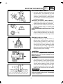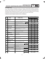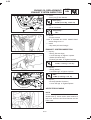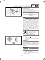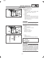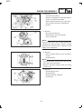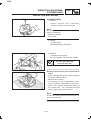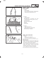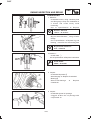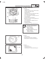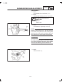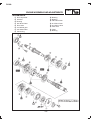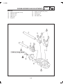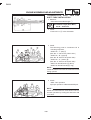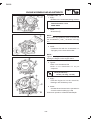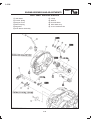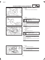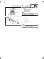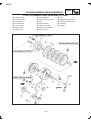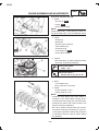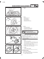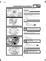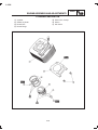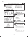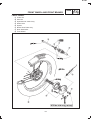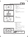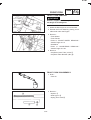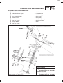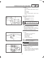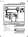
1
WORKSHOP MANUAL R-1 FOREWORD This Workshop Manual has been prepared for use by the Yamaha Motor India Private Ltd. Authorised Dealerships and their service personnel to attend to servicing of Crux Motorcycles. It is not possible to include entire service education into this Manual. It is assumed that persons using this book to perform maintenance and repairs on Crux Motorcycles have a basic understanding of mechanical concepts and procedures inherent to Motorcycle repair technology. Without such knowledge, attempted repairs or service of this model may render it unfit for use and / or unsafe. Yamaha Motor India Private Ltd. continually strives to improve all its models. Modifications and significant changes in specifications or procedures will be informed to all Yamaha Motor India Private Ltd. Authorised Dealerships through Service Actions and will wherever considered necessary, appear in future editions of this Workshop Manual. Service Department Yamaha Motor India Private Ltd. L-2 HOW TO USE THIS MANUAL MANUAL ORGANISATION This manual consists of chapters for the main categories of subjects. (See Illustrated symbols) 1st title 1 : This is the Title of the Chapter with its symbol on the upper right corner of each page. 2nd title 2 : This title indicates the Section of the chapter and only appears on the first page of each section. It is located in the centre of the page. 3rd title 3 : This title indicates a Subsection that is followed by step-by-step procedures accompanied by corresponding illustrations. EXPLODED DIAGRAMS To help identify parts and clarify procedure steps, there are Exploded Diagrams at start of each Removal and Disassembly section. 1. An easy-to-see Exploded Diagram 4 is provided for Disassembly and Assembly jobs. 2. Numbers 5 are given in the order of jobs in the exploded diagram. A number that is enclosed by a circle indicates a part. 3. An explanation of jobs and notes are presented in an easy-to-read way by the use of Symbol Marks 6 . The meaning of the Symbol Marks are given on the next page. 4. For jobs requiring more information, the step-by-step format supplements 7 are given in 1 addition to the exploded diagram. 4 ENGINE ASSEMBLY AND ADJUSTMENTS 2 ENG ENGINE ASSEMBLY PISTON RING, PISTON AND CYLINDER INSTALLATION 1. Install in following sequence 3 Expander Spacer (Oil Ring) ¿ 5 Side Rails (Oil Ring) À 2nd Ring Á Top Ring  NOTE : • Make sure to install the Piston Rings so that the GTP TOP1/GTP-TOP 2 marks are located on the upper side of the 2nd Ring/Top Ring • Lubricate the Piston and Piston Rings with Engine Oil. 6 2. Install : Piston ¿ Piston Pin À using piston pin tool Piston Pin replacer tool YSST - 207 Piston Pin Circlip Á New 7 R-3 ILLUSTRATED SYMBOLS Illustrated symbols 1 to 8 are designed as thumb tabs to indicate the chapters number and content. 1. General Information 3. Periodic inspection and adjustment GEN INFO 2. Specifications SPEC INSP ADJ 4. Engine ENG 5. Carburetion CARB 6. Chassis CHAS 7. Electrical ELEC 8. Troubleshooting TRBL SHTG Illustrated symbols 9 to 15 are used to identify the specifications appearing in the text. 9. Filling fluid 10.Lubricant 11.Special Tool 12.Torque 13.Wear Limit, Clearance 14.Engine speed 15.Resistance, Voltage, Current Illustrated symbols 16 to 21 in the exploded diagrams indicate the types of lubricants and lubrication points. 16. Apply engine oil 19. Apply wheel bearing grease 17. Apply gear oil 20.Apply lightweight lithium-soap base grease 18. Apply molybdenum disulfide oil 21. Apply molybdenum disulfide grease Illustrated symbols 22 and 23 in the exploded diagrams indicate where to apply locking agent and when to install new parts 22. Apply locking agent (LOCKTITE*) 23. Use New One L-4 INDEX GENERAL INFORMATION SPECIFICATIONS PERIODIC INSPECTION AND ADJUSTMENTS ENGINE CARBURETION CHASSIS ELECTRICAL TROUBLE SHOOTING GEN INFO 1 SPEC 2 INSP ADJ 3 ENG 4 CARB 5 CHAS 6 ELEC 7 TRBL SHTG 8 R-5 CHAPTER 1 GENERAL INFORMATION MOTORCYCLE IDENTIFICATION FRAME SERIAL NUMBER ....................................................... 1-1 ENGINE SERIAL NUMBER ...................................................... 1-1 IMPORTANT INFORMATION PREPARATION FOR DISASSEMBLY ..................................... 1-2 ALL REPLACEMENT PARTS ................................................... 1-3 GASKETS, OIL SEALS, AND O-RINGS ................................... 1-3 LOCK WASHERS/PLATES AND COTTER PINS ..................... 1-3 BEARINGS AND OIL SEALS .................................................... 1-3 CIRCLIPS .................................................................................. 1-3 SPECIAL TOOLS SPECIAL SERVICE TOOLS ..................................................... 1-4 SERVICE INSTRUMENTS ........................................................ 1-7 SPECIAL SERVICE MATERIALS ............................................. 1-8 L-6 MOTORCYCLE IDENTIFICATION GEN INFO MOTORCYCLE IDENTIFICATION FRAME SERIAL NUMBER The Frame Serial Number ¿ is stamped into the right side of the Steering Head Pipe. ENGINE SERIAL NUMBER The Engine Serial Number À is stamped on the top portion of RH Crankcase. ( Engine Serial Number does not contain Year and Month of production) XX X 5KA XXXXXX YEAR OF PRODUCTION MONTH CODE MODEL CODE UNIT PRODUCTION NUMBER Year of Production : Month Code : Starting Serial Number : 2 Digits standing for last two digits of year Eg. 0 0 - 2000, 0 1 - 2001 ...... One alphabet standing for Month Eg. A - January, B - February........ M - December ( I - Not Used for Month) 5KA 000101 WARNING Do not tamper with any of these numbers. It may lead to legal action. NOTE : Designs and sepecifications are subject to change without notice. 1-1 R-7 IMPORTANT INFORMATION GEN INFO IMPORTANT INFORMATION PREPARATION FOR DISASSEMBLY 1. Remove all dirt, mud, dust and foreign material before disassembly. 2. Use proper Tools and Cleaning Equipment. Refer to “SPECIAL SERVICE TOOLS”. 3. When disassembling the Motorcycle, keep mated parts together. This includes gears, Cylinder, Piston and other mated parts that have been “mated” through normal wear. Mated parts must be reused as an assembly or replaced. 4. During the Motorcycle disassembly, clean all parts and place them in trays in the order of disassembly. This will speed up assembly time and help assure that all parts are correctly reinstalled. 5. Keep Motorcycle and its parts away from any source of fire. 1-2 L-8 IMPORTANT INFORMATION GEN INFO ALL REPLACEMENT PARTS 1. Use only genuine Yamaha parts for all replacements. Use Yamalube Oil and Grease recommended by Yamaha for assembly and adjustment. Other brands may be similar in function and appearance, but inferior in quality. GASKETS, OIL SEALS, AND O-RINGS 1. All Gaskets, Seals and O-rings should be replaced when the Engine is overhauled. 2. All surfaces where Gasket, Oil Seal lips and O-rings contact must be cleaned and Lubricated. LOCK WASHERS/PLATES AND COTTER PINS 1. All Lock Washers/plates ¿ and Cotter Pins must be replaced when they are removed. Lock tab (s) should be bent along the Bolt BEARINGS AND OIL SEALS 1. Install the bearing (s) ¿ and Oil Seal (s) À with their manufacturers marks or numbers facing outward. (In other words, the stamped letters must be on the side exposed to view.) When installing Oil Seal (s), lubricate a light coating of lightweight lithium base grease to the seal lip(s). Oil the Bearings liberally when installing. WARNING CAUTION: Do not use compressed air to spin the Bearings dry. This causes damage to the Bearing surfaces. CIRCLIPS 1. All Circlips should be inspected carefully before reassembly. Always replace Piston Pin Clips after one use. Replace distorted Circlips. When installing a circlip ¿, make sure that the sharp-edged corner À is positioned opposite to the thrust Á it receives. See the sectional view of shaft Â. WARNING If the Circlip is fitted the wrong way it would cause it to jump off its groove and damage related components. 1-3 R-9 SPECIAL SERVICE TOOLS GEN INFO SPECIAL TOOLS SPECIAL SERVICE TOOLS The appropriate Special Service Tools are necessary for proper maintenance of the Motorcycle. Using the correct Special Service Tool will help to prevent damage caused by the use of improper tools or improvised techniques. The following is the detailed list of all Special Service Tools with their application. Refer to the list provided to avoid errors when placing an order for Special service tools. 5. Valve Clearance Adjusting Tool. YSST - 606 1. Magnet o Holder This tool is used to hold the Magneto when removing or installing the Magneto Securing Nut This tool is used to adjust Valve clearance. 6. Piston Pin Replacer 2. Magneto Puller with Spacer YSST - 602 This tool is used to replace Piston Pin. This tool is used to remove the Magneto 7. Rocker Arm Shaft Puller YSST - 608 (Old)YSST - 608A (New) 3. Valve Spring Compressor YSST - 603 This tool is used to to remove and install Valve Spring Assemblies. This tool is used to remove Rocker Arm Shaft. 8. Clutch Hub Holder YSST - 233 4. Piston Base YSST - 604 This tool is used to hold the Clutch Hub when removing or installing Clutch Main Shaft Nut. This tool is needed to support the Piston while installing Cylinder. 1-4 L-10 SPECIAL SERVICE TOOLS 9. Crank Shaft Removal Tool. YSST - 265 GEN INFO 13. Torx Bit (T - 30) YSST - 611 This tool is used to loosen or tighten the Cam Shifter Segment Screw. This tool is used to remove the Crank Shaft from the Crank Case. 10. Crank Shaft Installing Tool with spacer (a) YSST - 266 è ç (b) YSST - 267 14. Scraper YSST - 612 These tools are used for installation of Crank Shaft. This tool is used for scraping the sealent from Crankcase surface. 11. Driving Sprocket Holder YSST- 605 15. Feeler Gauge YSST - 615 This tool is used to hold the Driving Sprocket when removing or installing Driving Sprocket Nut This tool is used to check Valve Clearance. 16. Steering Nut Socket YSST - 621 12. Screw Driver (small). YSST - 609 This tool is used to loosen or tighten the Steering Ring Nut. To adjust Carburettor Pilot Screw. 1-5 R-11 SPECIAL SERVICE TOOLS GEN INFO 22. Engine Stand 17. Rear Shock Absorber Adjuster YSST 221 This fixture is used to hold the Engine for its disassembly and assembly. This tool is used to adjust spring preload of Rear Shock Absorbers. 18. T -Handle YSST - 213 23. Oil Seal Installing Tool. YSST - 622 This tool is used to hold the TFF plunger for loosening and tightening of Hex Socket Head Bolt This tool is used to install Oil Seal in Crank Case Cover#2. 24. Bearing Puller YSST - 623 19. T.F.F. Oil Seal Removing Tool. YSST - 270 This tool is used to remove the Bearing 6201 of the Axle Main. This tool is used to remove T.F.F. oil seal. 20. T.F.F. Oil Seal Installation Tool YSST-275 25. Bearing Puller YSST - 624 This tool is used to remove the Bearing 6202 of the Axle Drive This tool is used when installing the TFF Oil Seal. 21. Spanner - Speedometer Gear Nut. YSST - 237 26. Center Plug Spanner YSST-625 This tool is used to remove/install the Center Plug from Crank case Cover#1 (L.H.) This tool is used to loosen or tighten the Speedometer Gear Nut. 1-6 L-12 SERVICE INSTRUMENTS GEN INFO SERVICE INSTRUMENTS The following Service Instruments are necessary for complete and accurate tune up of Motorcycle 5. Vernier Calliper (150 mm) 1. Tachometer YSST - 613 This Instrument is used for checking the Engine RPM This instrument is used for measuring length, width & thickness of components 2. Timing light (SKC S14-121) 6. Micrometer (0-25 mm) & (50-75 mm) This instrument is used for checking ignition timing This instrument is used for measuring Piston size, Valve stem size etc. 7. ’CO’ Gas Analyser 3. Compression Gauge This instrument is used for measuring ‘CO’ concentration in exhaust of motorcycle This instrument is used for checking the engine compression 4. Mutimeter 8.Hydrometer This instrument is used for checking the electrical system. This instrument is used for measuring specific gravity of Battery Electrolyte 1-7 R-13 SERVICE INSTRUMENTS 9. Tyre pressure gauge GEN INFO 11. Torque Wrench (10-50 Ft-Lb) (20-100 Ft-Lb) This tool is used to tighten the Nuts/Bolts at a specified torque. This instrument is used for checking the Tyre Pressure 10. Vaccum Gauge 12. Feeler gauge This instrument is used for checking intake vaccum. This instrument is used to check clearance/ gaps between parts. SPECIAL SERVICE MATERIAL The following Service material are necessary to use at the time of assembly of various parts. 1. YAMAHA Bond TG-1215 2. LOCTITE Three Bond 1322 YAMAHA BOND TG-1215 This adhesive is used on mating surfaces while assembling Crankcase#1 and #2. This adhesive is used for Torx Screw tightening. 1-8 THREE BOND CHAPTER 2. SPECIFICATIONS GENERAL SPECIFICATIONS ....................................................2-1 MAINTENANCE SPECIFICATIONS ENGINE ...................................................................................... 2-4 CHASSIS .................................................................................... 2-10 ELECTRICAL .............................................................................. 2-13 GENERAL TORQUE SPECIFICATIONS ................................... 2-15 LUBRICATION POINTS AND LUBRICANT TYPE ENGINE ...................................................................................... 2-16 CHASSIS .................................................................................... 2-17 ENGINE LUBRICATION ROUTE ..................................................... 2-18 ENGINE BEARINGS ........................................................................ 2-20 CABLE ROUTING ............................................................................2-21 R-15 GENERAL SPECIFICATIONS SPEC GENERAL SPECIFICATIONS DESCRIPTION Model : Model Code : Engine model code: DIMENSIONS: Overall length Overall width Overall height Seat height Wheelbase Minimum ground clearance Minimum turning radius Dry weight : Basic weight : (With Oil and full Fuel Tank) ENGINE : Engine type Cylinder arrangement Displacement Bore X Stroke Compression ratio Starting system Lubrication system Max power Torque Oil type or grade : Engine oil SPECIFICATION CRUX 5KA1 5KA 1997 735 1055 780 1247 150 2000 105.5 113 mm mm mm mm mm mm mm kg kg Air-cooled 4-stroke, SOHC Forward-inclined, single cylinder 105.6 cm³ 49 X 56 mm 9:1 Kick starter Wet sump 7.6 BHP @ 7500 RPM 8 Nm @ 6000 rpm Yamalube 4-stroke Oil (20W50 Type SF) Oil capacity : Engine oil Periodic oil replacement Total amount Air filter : 1.0 L 1.2 L Washable, dual Foam, Wet type (Oil soaked) FUEL : Fuel Tank capacity Fuel reserve amount Carburetor : Type/ quantity Manufacturer Spark plug : Type/manufacturer Spark Plug gap 11 L 1.4 L VM17SH/1 (UCAL) DPR7EA/NGK 0.7 mm 2-1 L-16 GENERAL SPECIFICATIONS DESCRIPTION Clutch type : Transmission : Primary reduction system Primary reduction ratio Secondary reduction system Secondary reduction ratio Transmission type Operation Gear ratio SPECIFICATION Wet, Multiple disc Helical gear 68/18 (3.778 : 1) Chain drive 42/14 (3.00 : 1) Constant mesh 4-speed Left foot operation 33/11 (3.000) 27/16 (1.688) 24/20 (1.200) 21/23 (0.913) 1st 2nd 3rd 4th Primary Drive Grading Matching of Grades Gear Primary Drive GRADE A B GRADE C D GEAR PRIMARY DRIVE Chassis : Frame type Caster angle Trail Tyre : Type Size Manufacturer Type E Primary Driven Gear Assy. DRIVEN GEAR ASSY. SPEC A B C D E Double cradle 26.4º 83 mm With tube 2.50 - 18, 4 PR 2.75 - 18, 6 PR LOCAL MADE LOCAL MADE RIB TYPE RIB LUG TYPE Front Rear Front Rear Front Rear Tyre pressure (cold tyre) : Loading condition A* 0 ~ 90 kg (0 ~ 198 lbs) 24 PSI (1.70 kgf/cm²) 28 PSI (2.00 kgf/cm²) Loading condition B* 90 ~ 162 kg (198~408 lbs) Front 24 PSI (1.70 kgf/cm²) Rear 32 PSI (2.30 kgf/cm²) *Load is total weight of cargo, rider, passenger and accessories. Front Rear 2-2 R-17 GENERAL SPECIFICATIONS DESCRIPTION Brake : Front brake Rear brake SPEC SPECIFICATION Type Operation Type Operation Drum Brake (Dia 130 mm) Right hand operation Drum brake (Dia 130 mm) Right foot operation Suspension : Front suspension Rear suspension Shock absorbser : Front shock absorber Rear shock absorber Wheel travel : Front wheel travel Rear wheel travel Electrical : Ignition system Generator system Battery type Battery capacity Headlight type : Headlight bulb type Bulb (voltage - wattage x quantity) : Headlight Tail/Brake light Flasher light Meter light “NEUTRAL” indicator light “HIGH BEAM” indicator light “TURN” indicator light Telescopic fork Swingarm Coil spring/Oil damper Coil spring/Oil damper 110 mm 70 mm CDI (Digital) Flywheel magneto LOCAL MADE 12V - 2.5 AH Bulb type Krypton bulb 12V - 35W/35W x 1 12V - 5W/21W x 1 12V - 10W x 4 12V - 2W x 1 12V - 3.4W x 1 12V - 3.4W x 1 12V - 3.4W x 1 2-3 L-18 MAINTENANCE SPECIFICATIONS SPEC MAINTENANCE SPECIFICATIONS ENGINE DESCRIPTION Cylinder : Bore size SPECIFICATION 49.000 ~ 49.020 mm (in five grades) Piston : Piston to Cylinder Clearance <Limit> Piston size “D” Cylinder Piston Grading 0.017 ~ 0.021 mm <0.12mm> 48.962 ~ 48.981 mm (in five grades) Matching of Grades Piston Colour Mark Colour Mark Punch Mark Red Orange Green Violet Blue H D Measuring point “H” Piston offset Piston offset direction Piston pin bore inside diameter Piston pin outside diameter Piston rings : Top ring : Type Dimensions (B x T) End gap (installed) <Limit> T Side clearance (installed) <Limit> 2nd ring : Type Dimensions (B x T) B T End gap (installed) <Limit> Side clearance <Limit> Oil ring : Dimensions (B x T) B T End gap (installed) Side Clearance (For Rail Upper and Rail Lower) Cylinder Letter Punch Mark A B C D E 4.5 mm 0.5 mm Intake side 13.002 ~13.013 mm 12.996 ~ 13.000 mm Barrel 1.0 x 1.95 mm 0.10 ~ 0.25 mm <0.35mm> 0.030 ~ 0.065 mm <0.115m> B Taper 1.0 x 1.9 mm 0.25 ~ 0.40 mm <0.50mm> 0.020 ~ 0.065 mm <0.115mm> 2.0 x 2.15 mm 0.2 ~ 0.7 mm 0.040 2-4 R-19 MAINTENANCE SPECIFICATIONS DESCRIPTION Cylinder head : <Warp limit> SPECIFICATION <0.03 mm (0.0012 in)> * Lines indicate straightedge measurement. Camshaft : Drive method Cam dimensions Intake Chain Drive C B Exhaust SPEC B “A” <Limit> “B“ <Limit> “C“ “A“ <Limit> “B“ <Limit> “C“ 25.356 ~ 25.456 mm <25.326 mm> 20.989 ~ 21.089 mm <20.959 mm> 4.4055 mm 21.360 ~ 21.460 mm <21.330 mm> 21.001 ~ 21.101 mm <20.971 mm> 4.4114 mm Rocker Arm/ Rocker Arm Shaft : Inside diameter (Rocker Arm) 10.000 ~ 10.015 mm <10.03 mm> 9.981 ~ 9.991 mm <9.95 mm> <Limit> Outside diameter (Rocker Armshaft) <Limit> Cam chain : Cam chain type/No. of links Cam chain adjustment method Valve, Valve Seat, Valve Guide : Valve clearance (cold) IN EX Valve dimensions : BUSH CHAIN / 90 Automatic 0.08 ~ 0.12 mm 0.10 ~ 0.14 mm C B D A Head Dia. “A” head diameter “B” face width “C” seat width “D” margin thickness Face Width Seat Width IN EX IN EX IN EX IN EX 22.90 ~ 23.10 mm 19.90 ~ 19.10 mm 1.98 mm 2.26 mm 0.9 ~ 1.1 mm 0.9 ~ 1.1 mm 0.60 mm 1.00 mm 2-5 Margin Thickness L-20 MAINTENANCE SPECIFICATIONS DESCRIPTION Stem outside diameter <Limit> Guide inside diameter <Limit> Stem to guide clearance <Limit> IN EX IN EX IN EX IN EX IN EX IN EX SPECIFICATION 4.975 ~ 4.990 mm 4.960 ~ 4.975 mm <4.950 mm> <4.935 mm> 5.000 ~ 5.012 mm 5.000 ~ 5.012 mm <5.035 mm> <5.035 mm> 0.005 ~0.0325 mm 0.0125 ~ 0.026 mm <0.075 mm> <0.075 mm> 0.010 mm IN EX IN EX 0.9 ~ 1.1 mm 0.9 ~ 1.1 mm <1.6 mm> <1.6 mm> Stem runout limit Valve seat width <Limit> Valve spring : Free length IN EX <Limit> IN EX Set length (valve closed ) IN EX <Tilt limit> IN EX Compression pressure (installed) IN EX Direction of winding (top view) Crankshaft : Crank width “A” <Runout limit “C”> Big end side clearance “D” <Small end free play limit “F”> SPEC 39.62 mm 39.62 mm 38.17 mm 38.17 mm 25.6 mm 25.6 mm 2.5°/1.7 mm 2.5°/1.7 mm 142-221 Nm (14.5-22.5 kgf) 142-221 Nm (14.5-22.5 kgf) Clockwise 46.95 ~ 47.00 mm <0.03 mm> 0.15 ~ 0.45 mm <0.8 mm> Shifter : Shifter type Kick starter : Kick starter type Kick clip friction force Cam Drum and Guide bar Kick and mesh type 7.8 ~ 11.8 Nm (0.8 ~ 1.2 kgf) 2-6 R-21 MAINTENANCE SPECIFICATIONS DESCRIPTION Clutch : Friction plate thickness Quantity <Friction plate wear limit> Clutch Plate thickness Quantity <Wrap limit> Clutch Spring free length Quantity Minimum length Clutch release method <Push rod bendinglimit> Carburetor : I. D. Mark Main Jet Main Air Jet size Jet needle Needle jet Cut away Pilot outlet Pilot jet Valve seat size Starter jet Fuel level (with special tool) SPEC SPECIFICATION 2.90 ~ 3.10 mm 5 pcs. <2.80 mm> 1.05 ~ 1.35 mm 4 pcs. 0.05 mm 33 mm 4 pcs. 31.0 mm Inner push, cam push <0.5 mm> 5KA100 #102.5 1.4 4DP19-2 E-OM (860) 3.0 1.1 # 12.5 1.5 #30 2.5 ± 0.5 mm Above the Joint Line of MCB (Main Chamber Body) and FCB (Float Chamber Body) 9.3±1 mm 1,300 ~1,500 r/min. (M.J.) (M.A.J.) (J.N.) (N.J.) (C.A.) (P.O.) (P. J.) (V.S.) (G.S.1) (F.L.) Float height Engine idle speed Intake vaccum New Vehicle Market Run Vehicle Lubrication system : Oil filter type Oil filter type Tip Clearance “A” or “B” <Limit> Side clearance <Limit> Housing and rotor clearance <Limit> 24.0 ~ 29.4 kPa 29.3 ~ 34.7 kPa Wire mesh type Trochoid type 0.15 mm <0.2 mm> 0.06 ~ 0.10 mm <0.15 mm> 0.06 ~ 0.10 mm <0.15 mm> 2-7 L-22 MAINTENANCE SPECIFICATIONS SPEC TIGHTENING TORQUE (ENGINE) Part to be tightened Parts name Thread size Q'ty Cylinder Head Bolt M8 4 Tightening torque Nm m.kg ft.lb 22 2.2 17 Bolt M6 2 10 1.0 7.2 Spark Plug - M12 1 17.5 1.75 12.6 Cylinder Head Side Cover Bolt M6 2 10 1.0 7.2 Valve Cover - M45 2 17.5 1.75 13 CDI Magneto Rotor Bolt M6 1 70 7.0 51 Stopper Guide Bolt M6 1 10 1.0 7.2 Adjust Screw Nut M5 2 8 0.8 5.8 Sprocket (Timing Chain) Bolt M8 1 20 2.0 14.5 Plate To Head Cylinder Bolt M6 1 10 1.0 7.2 Plug (Tensioner Assembly) Plug M8 1 8 0.8 5.8 Tensioner Assembly Bolt M6 2 10 1.0 7.2 Oil Pump Assembly Screw M6 2 7 0.7 5.1 Drain Plug Screw M12 1 20 2.0 14.5 Pump Cover Screw M5 1 4 0.4 3.6 Intake Manifold Bolt M6 2 10 1.0 7.2 Carburetor Joint (Manifold) Bolt M6 2 10 7.2 7.2 Carburetor Joint (Air filter) Screw M4 1 2 0.2 1.5 Air filter Case Bolt M6 2 7 0.7 5.1 Muffler (Cylinder Head) Bolt M6 1 7 0.7 5.1 Muffler Assembly Crankcase 1 and 2 Bolt M8 1 15 1.5 11 Bolt M6 2 10 1.0 7.2 Bolt M6 6 10 1.0 7.2 Bolt M6 2 10 1.0 7.2 Bolt M6 5 10 1.0 7.2 Crankcase Cover 1 Cover Chain Case 1 Crankcase Cover 2 Bolt M6 2 10 1.0 7.2 Screw M6 2 7 0.7 5.1 Bolt M6 7 10 1.0 7.2 Bolt M6 2 10 1.0 7.2 Plate Screw M6 1 7 0.7 5.1 Timing Mark Check Plug Screw M14 1 7 0.7 5.1 Center Plug Screw M32 1 7 0.7 5.1 Kick Crank Assembly Nut M12 1 50 5.0 36 Primary Drive Gear Nut M12 1 70 7.0 51 Pressure Plate Bolt M8 4 6 0.6 4.3 Clutch Boss Nut M12 1 60 6.0 43.5 Push Rod Nut M6 1 8 0.8 5.8 Plate Nut M6 2 7 0.7 5.1 Drive Sprocket Nut M6 1 10 1.0 7.2 2-8 Remark Use Lock W. R-23 MAINTENANCE SPECIFICATIONS SPEC TIGHTENING TORQUE (ENGINE) Tightening sequence Cylinder Head Part to be tightened Parts name Thread size Q'ty Shift Pedal Bolt M6 Segment Screw Stopper lever Bolt Sensor Assembly Neutral Switch Assembly Crankcase Tightening torque Nm m.kg ft.lb 1 10 1.0 7.2 M6 1 12 1.2 9 M6 1 10 1.0 7.2 Bolt M6 2 10 1.0 7.2 - M10 1 4 0.4 3 Remark Torx Bolt t Left - hand Right - hand 2-9 L-24 MAINTENANCE SPECIFICATIONS SPEC CHASSIS DESCRIPTION Steering system : (as applicable) Steering Bearing type No./size of steel balls (upper) (lower) Front suspension : Front Fork travel Fork Spring free length <Limit> Spring rate (K1) (K2) Stroke (K1) (K2) Oil grade Rear suspension : Shock Absorber travel Spring free length Fitting length Spring rate (K1) (K2) Stroke (K1) (K2) Swingarm : <Free play limit> End Side Front wheel : Type Rim size Rim material <Rim run out limit> Radial Lateral Rear wheel : Type Rim size Rim material <Rim rounout limit> Radial Lateral Drive chain : Type/manufacturer Number of links Chain slack SPECIFICATION OLD NEW Ball and Race Bearing Retainer Ball cage 22 pcs. / 3/16 in 19 pcs. / 1/4 in 19 pcs. / 1/4 in 16 pcs. / 1/4 in 110 mm 320.9 mm 315.9 mm 7.4 N/mm 13.2 N/mm 0 ~ 28 mm 28 ~ 110mm Special YAMAHA oil. 70 mm 205.4 mm 197.4 mm 18.6 N/mm 27.8 N/mm 0 ~ 40 mm 40 ~ 70 mm <1.0 mm> <1.0 mm> Spoke wheel 1.6 x 18” Steel <0.5 mm> <0.8 mm> Spoke wheel 1.6 x 18” Steel <0.5 mm> <0.8 mm> 428V2 / Local MADE 112 20~30 mm 2-10 R-25 MAINTENANCE SPECIFICATIONS DESCRIPTION Front Drum Brake : Type Brake Drum inside diameter <Wear limit> Lining Thickness <Wear limit> Shoe Spring free length Rear drum brake : Type Brake Drum inside diameter <Wear limit> Lining Thickness <Wear limit> Shoe spring free length Free Plays : Brake Lever free play (At lever end) Brake Pedal free play Clutch Lever free play (at lever end) Throttle Grip free play SPECIFICATION Leading, Trailing 130mm <131> 4.0 mm <2 mm> 36.5mm Leading, Trailing 130mm <131> 4.0 mm <2 mm> 36.5 mm 10 ~ 15 mm 20 ~ 30 mm 10 ~ 15 mm 3 ~ 7mm 2-11 SPEC L-26 MAINTENANCE SPECIFICATIONS SPEC TIGHTENING TORQUE (CHASSIS) * Note : 1. First tighten the Ring Nut approximately 45.5 Nm (4.55 m.kg 32.3 ft.lb) by using the torque wrench then loosen the Ring Nut one turn. 2. Retighten the Ring Nut to specifications 2-12 R-27 MAINTENANCE SPECIFICATIONS SPEC ELECTRICAL DESCRIPTION Voltage : Ignition system : Ignition timing (B.T. D. C) Advancer Type CDI : Magneto model/manufacturer Sensor Coil (Color) CDI Unit Model/manufacturer IgnitionCoil : Model/Manufacturer Primary Coil Resistance Secondary Coil Resistance Spark Plug Cap : Type Resistance Charging System : Type Flywheel Magneto : Model/Manufacturer Charging Voltage Charging Coil Resistance Lighting : Lighting Voltage SPECIFICATION 12V 7º at 1400 r/min Electrical type Digitally Controlled 5KA/DENSO 240 Ω ± 20% 5KA/ Denso (Japan) 5KA/DENSO 0.16 Ω ± 15% 4.2 KΩ ± 20% Resin type 5 kΩ at 20 ºC (68ºF) Flywheel Magneto 5KA/DENSO 14 ~ 15V @ 5000 RPM 0.82 Ω ± 20% (68ºF) (Min) (Max) 12V/3,000 r/min 15V/8,000 r/min 0.62Ω ± 20 % (68ºF) Lighting Coil Resistance Rectifier/Regulator : Type Model/Manufacturer No load regulated voltage Capacity Withstand voltage Battery : Specific Gravity Horn: Type Quantity Model/Manufacturer Maximum Amperage Flasher relay: Type Model/Manufacturer Self cancelling device Flasher frequency Wattage Semi conductor-Short Circuit Type 36L/Local Made/CKD 13 ~ 14V 8A 400 V 1.230 Plane type 1 pc. 36L/Local Made 1.5 A Semi transistor type 4LS/Local Made No 60 ~ 120 cycles/min 10W X 2 2-13 L-28 MAINTENANCE SPECIFICATIONS Circuit Breaker : Type Amperage for individual circuit X quantity : Main Reserve Fuse 10A X 1pc. 10A X 1pc. 2-14 SPEC R-29 GENERAL TORQUE SPECIFICATION SPEC GENERAL TORQUE SPECIFICATIONS This chart specifies torque for standard fasteners with standard I.S.O. pitch threads. Torque specification for special components or assemblies are included in applicable section of this book. To avoid warpage, tighten multi-fastener assemblied in a criss-cross fashion, in progressive stages, until full torque is reached. Unless otherwise specified, torque specifications call for clean, dry threads. Components should be at room temperature. A (Nut) B (Bolt) 10 12 14 17 19 22 6 mm 8 mm 10 mm 12 mm 14 mm 16 mm mm mm mm mm mm mm General Torque specifications Nm 6 15 30 55 85 130 m•kg ft•lb 0.6 1.5 3.0 5.5 8.5 13.0 4.3 11 22 40 61 94 A : Distance across flats B : Outside thread diameter 2-15 L-30 LUBRICATION POINTS AND LUBRICANT TYPE SPEC LUBRICATION POINTS AND LUBRICANT TYPE ENGINE Lubrication points (part name) Lubricant type Oil Seal lips (all) Bearing Retainer (all) Bolt (Cylinder Head) O-ring (Cylinder Head Side Cover and Valve Cover) Crank Pin Connecting Rod (big end) Piston Pin Valve Stem and Valve Guide Oil Seal (Valve Stem End) Rocker Arm Shaft and Rocker Arm Cam and Bearing (Camshaft) Push Rod Primary Driven Gear and Main Axle Push Lever Axle Rotary Filter and Oil Pump Sliding Gear (Transmission) Kick Axle Shaft Axle Drive Shift Fork and Guide Bar Shift Cam and Bearing (shift cam) Crankcase Mating Surfaces Yamaha bond No. 1215 Crankcase Cover 1 and Grommet Yamaha bond No. 1215 2-16 R-31 LUBRICATION POINTS AND LUBRICANT TYPE SPEC CHASSIS Lubrication points (part name) Lubricant type Gear Unit (Gear Meter and Drive) Oil Seal Lips (all) Pivot Shaft (Swingarm) Pivoting Points (Brake Pedal Shaft and Frame) Ball and Ball Race (Steering Head) Tube Guide (Right Grip) Pivoting points (Brake Lever and Clutch Lever) Pivoting Point (Brake Shoe Plate) Cable End (Front Brake and Clutch) Pivoting Points (Sidestand Mainstand and Rear Footrest) Brake Camshaft (Cam and Shaft) 2-17 L-32 ENGINE LUBRICATION ROUTE SPEC Engine Lubrication route CAUTION: WARNING DO NOT DAMAGE CRANK CASE SURFACES, OTHERWISE OIL LEAKAGE WILL START 2-18 R-33 ENGINE LUBRICATION ROUTE Engine Lubrication route CAUTION: WARNING FOR IMPROVED PERFORMANCE, ALWAYS USE YAMALUBE OIL 2-19 SPEC L-34 ENGINE BEARINGS ENGINE BEARINGS 2-20 SPEC R-35 CABLE ROUTING CABLE ROUTING SPEC É Flasher light lead (left) of the right side. Ê Horn C Pass the Meter Cable Ç and the Brake Cable through the Ë Flasher light lead (right) A Pass the Clutch Cable À, cable guide. and the Handle-bar Switch D Pass the Main Harness È through the wire Guide. Lead Á through the cable guide of the left side. B Pass the Throttle Cable Å, and the Brake Cable Ä and the Front Brake switch lead Æ through the Cable Guide ¿ Handlebar switch (left) À Clutch cable Á Handlebar switch lead  Speedometer à Indicator panel Ä Brake Cable front Å Throttle cable Æ Brake switch lead Ç Speedometer cable È Wireharness à  À B A Ä ¿ Æ Á À Ä Ç Å É È Ë Ê C D 2-21 Å L-36 CABLE ROUTING ¿ Headlight assembly À Handlebar switch lead Á Speedometer cable  Cable guide à Clutch cable Ä Air vent hose Å Fuse Æ CDI unit Ç Clamp È Stop/tail light É Flasher light lead (right) Ê Flasher light Ë Battery Ì Battery breather hose Í Neutral switch lead Î Over flow hose Ï Crankcase breather hose Ð Brake cable A Pass the wireharness through the cable guide. B Inser the air vent hose to the hole of the flap. C Align the white marking of wireharness with the frame clamp. D Tighten the battery negative (-) lead and th ground lead of the wireharness together. E Pass the battery breather hose through the hole of the SPEC upper left side of the engine bracket. F Pass the battery breather hose, the crankcase breather hose and the carburetor overflow pipe through footrest clamps G Pass the battery breather hose, thse crankcase breather hose and the carburetor overflow pipe to the left side of crankcase. H Pass the magneto lead to the outside of the flange of the chain cover. 1 5 2 6 11 7 9 13 8 10 12 4 14 18 15 3 19 17 2-22 R-37 SPEC CABLE ROUTING ¿ Throttle cable À High tension cord Á Ignition Coil  Band à Brake cable front Ä Speedometer Å Brake switch lead Æ Clutch cable Ç Breather hose A Pass the high tension cord À through the cable guide to the inside of throttle cable ¿ and the clutch cable Æ. B Tighten the ground lead and ignition coil together C Pass the throttle cable ¿ through the headlight stay. D Pass breather hose through upper right side hole of frame bracket engine. Ã Å Â Ä C ¿ D Ç Á A B ÀÂ Æ ¿ 2-23 L-38 SPEC CABLE ROUTING ¿ Clamp à Stop/tail light lead À Rectifier regulator Ä Wireharness Á Flasher relay Å Battery  Flasher light lead Æ CDI unit assy. A Clamp the battery positive (+) lead to the batterybox. B Insert hose Air Bent to holder of frame. À ¿ Á A B Á Æ Å Ä Â Ã Â 2-24 R-39 CHAPTER 3 PERIODIC INSPECTION AND ADJUSTMENTS PERIODIC MAINTENANCE / LUBRICATION INTERVALS .......3-1 SIDE COVER, SEAT AND FUEL TANK REMOVAL ...................................................................................3-3 INSTALLATION ...........................................................................3-5 ENGINE VALVE CLEARANCE CHECKING ADJUSTMENT ....................3-6 IDLING CO MEASUREMENT, AND ADJUSTMENT .................3-8 THROTTLE CABLE ADJUSTMENT SPARK PLUG INSPECTION AND ADJUSTMENT....................3-10 IGNITION TIMING CHECK ........................................................3-11 COMPRESSION PRESSURE MEASUREMENT ...................... 3-13 ENGINE OIL LEVEL INSPECTION ............................................3-14 ENGINE OIL REPLACEMENT ...................................................3-14 AIR FILTER CLEANING .............................................................3-16 CLUTCH CABLE ADJUSTMENT ...............................................3-17 CHASSIS FRONT BRAKE ADJUSTMENT .................................................3-18 REAR BRAKE ADJUSTMENT ...................................................3-18 BRAKE SHOE INSPECTION .....................................................3-19 BRAKE LIGHT SWITCH ADJUSTMENT ...................................3-19 DRIVE CHAIN SLACK ADJUSTMENT ...................................... 3-20 STEERING HEAD INSPECTION ...............................................3-22 FRONT FORK INSPECTION .....................................................3-24 REAR SHOCK ABSORBER ADJUSTMENT .............................3-24 TYRE INSPECTION ...................................................................3-25 SPOKE INSPECTION AND TIGHTENING ................................3-27 WHEEL INSPECTION ................................................................3-27 ELECTRICAL BATTERY INSPECTION ............................................................3-28 FUSE INSPECTION ...................................................................3-30 HEADLIGHT BEAM ADJUSTMENT .......................................... 3-31 HEADLIGHT BULB REPLACEMENT ........................................3-31 L-40 INSP ADJ INTRODUCTION/ PERIODIC MAINTENANCE/LUBRICATION INTERVALS INTRODUCTION This chapter includes all information necessary to perform recommended inspections and adjustments. These preventive maintenance procedures, if followed, will ensure more reliable Motorcycle operation and a longer service life. The need for costly overhaul work will be greatly reduced. This information applies to Motorcycles already in service as well as to new Motorcycles that are being prepared for sale. All service technicians should be familiar with this entire chapter. PERIODIC MAINTENANCE/LUBRICATION INTERVALS SERVICES SNO ITEM OPERATION FREE I 1 VALVES Check Valve clearances, adjust if necessary 2 SPARK PLUG Check condition, gap 3 Clean and reset if necessary CARBURETOR Replace PAID II III IV V VI EVERY 10,000 km Check idle speed, Choke Lever operation. Tune if necessary. Clean, inspect & lubricate. (replace if necessary) 4 *AIR FILTER 5 FUEL LINE 6 FUEL FILTER 7 ENGINE OIL 8 OIL STRAINER Wash with petrol. 9 BRAKE-FRONT & Check operation/ Adjust if necessary. REAR Grease the brake cam. BRAKE SHOES Check for wear, replace if necessary. 10 Check for free flow of petrol, cleanliness of Bowl/filter. Replace if necessary Replace with recommended oil (Warm engine before draining) FRONT & REAR 11 CLUTCH 12 REAR ARM PIVOT Check alignment marks on Push Lever and Crankcase L.H. Adjust if necessary Check Rear Arm assembly for looseness. Tighten with specified torque if necessary. Repack grease 13 WHEELS 14 WHEEL BEARING 15 16 Check Fuel Hose, for cracks or damage. Replace if necessary. EVERY 10,000 km Check runout, Spoke tightness, damage; Correct it if necessary. Check Bearing assembly for looseness, damage; Replace if necessary. Repack grease STEERING RACE Check Race Ball Assy. for looseness, Tighten/ BALL Replace if necessary. FRONT FORKS Check operation/oil leakage, Repair if necessary. Repack grease Replace Oil 3-1 EVERY 10,000 km EVERY 10,000 km EVERY 10,000 km EVERY 2000km R-41 PERIODIC MAINTENANCE/LUBRICATION INTERVALS INSP ADJ SERVICES SNO ITEM OPERATION 17 REAR SHOCK 18 DRIVE CHAIN 19 NUTS, BOLTS Check all Chassis fittings and fasteners for AND FASTENERS looseness. Tighten as per specification. CENTERSTAND Check operation and lubricate if necessary 20 FREE I PAID II III IV V VI EVERY 2000km Check operation/oil leakage, Replace if necessary. ABSORBER Check Chain slack, alignment. Adjust if necessary. Clean and lubricate. AND SIDE STAND 21 BATTERY Check electrolyte level and top it up with distilled water if necessary. Check specific gravity. Check Breather Pipe for blockage and routing. 22 CONTROL CABLES, Check operation, free play, Cable damage - THROTTLE Readjust or replace as required EVERY MONTH - CLUTCH - FRONT BRAKE It is recommended that above be authorised YAMAHA MOTOR INDIA PRIVATE LIMITED dealer. * Service more frequently when the vehicle is driven in dusty areas. 3-2 L-42 SIDE COVERS, SEAT AND FUEL TANK INSP ADJ SIDE COVERS, SEAT AND FUEL TANK REMOVAL SIDE COVER (LH) 2 1. Remove • Side Cover (LH) 3 1 3 2 3 2 ææææææææææææææææææææææææææææææææææ Removal steps : • Open the Lock ¿ using Main Switch Key. • Pull the Lug À towards you to remove it from the Fuel Tank. • Slide the Side Cover towards the rear end of the Motorcycle for removing the Lug Á from the Chassis. ææææææææææææææææææææææææææææææææææ REMOVAL SIDE COVER (RH) 1. Remove • Side Cover (RH) ææææææææææææææææææææææææææææææææææ Removal steps : • Remove the Screw ¿ • Pull the lug À towards you to remove it from the Fuel Tank. • Slide the Side Cover towards the rear end of the Motorcycle for removing the lug Á ææææææææææææææææææææææææææææææææææ 1 3 2 3-3 R-43 SIDE COVERS, SEAT AND FUEL TANK 1 2 INSP ADJ REMOVAL SEAT 1. Remove • Side Cover LH and RH • Bolts 2 Nos • Seat ææææææææææææææææææææææææææææææææææ Removal steps : • Open bolts ¿ and À inside the side covers. • Lift the front of the Seat and slide it forward. REMOVAL FUEL TANK 1. Disconnect • Fuel Hose NOTE : • Position the Fuel Cock ¿ to the ‘OFF’, disconnect the Fuel Hose. • Place a rag under the Fuel Line to absorb any spilt fuel. WARNING • Gasoline is highly flammable. • Avoid spilling of fuel on the hot Engine. 2. Remove • Bolt (Fuel Tank) ¿ • Plate À • Damper Rubber Á • Fuel Tank  3-4 L-44 SIDE COVERS, SEAT AND FUEL TANK INSP ADJ INSTALLATION Reverse the REMOVAL procedure. Note the following points. 1. Install • Fuel Tank ¿ • Damper Rubber À • Plate Á • Bolt  • Fuel Hose à Bolt (fuel tank) 20 Nm (2.0 mkg; 14.4 ft.lb) NOTE : • Keep the projection on plate Á downward. 2. Install • Seat • Bolts ¿ and À a 2 b NOTE : • Insert the projection ç on the rear of the seat into the receptacles è on the Chassis, then push down front of the seat and tighten the bolts. 1 Bolt (Seat) 3.8 Nm (0.38 mkg, 3.0 ft.lb) 3. Install • Side Cover (LH) ¿ and lock with Key 1 4. Install • Side Cover (RH) À 2 5. Tighten • Screw Á 3-5 R-45 VALVE CLEARANCE CHECKING AND ADJUSTMENT INSP ADJ ENGINE VALVE CLEARANCE CHECKING AND ADJUSTMENT NOTE : Valve clearance checking and adjustment should be made with the Engine in cold condition, at room temperature. When the Valve clearance is to be measured or adjusted, the Piston must be at Top Dead Center (T.D.C.) on the compression stroke and marking on Cam Sprocket should be aligned with the marking on Cylinder Head. 1. Remove : • Side Covers • Seat • Fuel Tank Refer to “SIDE COVERS, SEAT AND FUEL TANK” section Page no 3-3 2. Remove : • Spark Plug • Bolts (Cylinder Head Side Cover) ¿ 2 Nos • Cylinder Head Side Cover À • Valve Cover (intake side) Á • Valve Cover (exhaust side)  3. Remove : • Timing Check Plug (with O-ring) ¿ • Center Plug (with O-ring) À 4. Measure : • Valve clearance (Intake and Exhaust) ¿ using Feeler Gauge Out of specification Ÿ Adjust. Feeler Gauge : YSST - 615 Valve clearance (cold) Intake : 0.08 ~ 0.12 mm Exhaust : 0.10 ~ 0.14 mm 3-6 L-46 VALVE CLEARANCE CHECKING AND ADJUSTMENT INSP ADJ ææææææææææææææææææææææææææææææææææ Checking steps : Measurement steps : • Rotate the Crankshaft anticlockwise to align the slit ç third mark on the rotor with the stationary pointer è on the Crankcase Cover LH when the Piston is at Top Dead Center (T.D.C.) and in compression stroke. • Measure the Valve clearance by using a feeler gauge. Feeler Gauge YSST 615 Out of specification Ÿ Adjust clearance. ææææææææææææææææææææææææææææææææææ 5. Adjust : • Valve clearance ææææææææææææææææææææææææææææææææææ Adjustment steps : • Loosen the Locknut ¿ • Turn the Adjuster À in or out with the Valve adjusting tool Á until specified clearance is obtained. Valve adjusting tool : YSST - 606 Turning in ŸValve clearance is decreased. Turning outŸValve clearance is increased. • Hold the Adjuster to prevent it from moving and tighten the Locknut. Locknut : 8 Nm (0.8 m • kg, 5.8 ft • lb) • Measure the Valve clearance. • If the clearance is incorrect, repeat above steps until specified clearance is obtained. ææææææææææææææææææææææææææææææææææ 6. Install • Timing Check Plug (with O-ring ) ¿ • Center Plug (with O-ring) À 3-7 R-47 IDLING CO. MEASUREMENT AND ADJUSTMENT INSP ADJ 7. Install • Valve Covers (with O-ring) ¿ • Spark Plug • Cylinder Head Side Cover À Valve cover (intake and exhaust) : 17.5 Nm (1.75 m kg, 13 ft-lb) Bolts (cylinder head side cover) : 10 Nm (1.0 m kg, 7.2 ft-lb) 8. Install • Seat • Side Covers • Fuel Tank Refer to the “SIDE COVERS, SEAT AND FUEL TANK” section Page no 3-3 IDLING CO. MEASUREMENT ADJUSTMENT AND 1. Start the Engine and let it warm up by running the Motorcycle approx. 4 kms. 2. Attach : • Inductive Tachometer to the Spark Plug Lead. Tachometer : YSST - 613 3. Check : • Engine idling speed (standard) Out of specification Ÿ Adjust. Turn the Throttle Stop Screw ¿ in or out until specified idling speed is obtained. 1 Turning IN Increasing in rpm Turning OUT Decrease in rpm Engine idling speed : 1,300 ~ 1,500 r/min NOTE : Before checking Engine idle RPM always check throttle cable free movement and free play. 4. Insert : • Sampling probe ¿ (CO. tester ) to the exhaust pipe À 1 CO.concentration : 2.5% ± 1.5 V/V 2 Out of specification Adjust. 3-8 L-48 IDLING ‘CO’ MEASUREMENT AND ADJUSTMENT/ THROTTLE CABLE ADJUSTMENT INSP ADJ 5. Adjust : • ‘CO’ concentration ææææææææææææææææææææææææææææææææææ Adjustment steps : • Turn the pilot screw ¿ in or out until the specified ‘CO’ concentration is obtained. Turning in ‘CO’ concentratin decreases Turning out ‘CO’ concentration increases 2 1 NOTE : For adjusting the Engine idling speed use the throttle stop screw À . Do not adjust Engine idle RPM by using the pilot screw ¿ • After adjusting, ‘CO’ concentration as specified, remove the ‘CO’ tester, make sure that the Engine idling speed has not changed. ææææææææææææææææææææææææææææææææææ THROTTLE CABLE ADJUSTMENT NOTE : Prior to adjusting the Throttle Cable free play, the Engine idling speed should be adjusted. 1. Check : • Throttle cable free play ç Out of specification Ÿ Adjust. Free play : 3 ~ 7 mm At Throttle Grip flange 2. Adjust : • Throttle Cable free play ææææææææææææææææææææææææææææææææææ Adjustment steps : NOTE : Never accelerate the Throttle when stopping the Engine. 3-9 R-49 THROTTLE CABLE ADJUSTMENT/ SPARK PLUG INSPECTION INSP ADJ • Loosen the Locknut ¿ on the Throttle Cable. • Turn the Adjuster À in or out until the specified free play is obtained. Turning IN ç Ÿ Free play is increased. Turning OUT è Ÿ Free play is decreased. • Tighten the locknut ¿. WARNING After adjusting, turn the Handlebar to the right and to the left to ensure that this does not cause the Engine idling speed to change. SPARK PLUG INSPECTION 1. Remove : • Spark Plug Cap • Spark Plug WARNING CAUTION: Before removing the Spark Plug, use compressed air to blow away any dirt accumulated in the Spark Plug wells to prevent it from falling into the Cylinder. 2. Check : • Spark Plug Type / Number Incorrect Replace Standard Spark Plug : DPR7EA (NGK) 3. Inspect : • Center Electrode ¿ Wear/damage Ÿ Replace Spark Plug. • Ground Electorde À Abnormal color Ÿ Replace Spark Plug. Normal color is medium-to-light tan color 4. Clean : • Spark Plug (with Spark Plug cleaner or wire brush) 5. Measure : • Spark Plug gap (with a wire gauge) Out of specification Ÿ Adjust gap. Spark Plug Gap: 0.7 mm 3-10 L-50 SPARK PLUG INSPECTION/ IGNITION TIMING CHECKING PROCEDURE INSP ADJ 6. Install : • Spark Plug Spark Plug : 17.5 Nm (1.75 mkg, 12.6 ftlb) NOTE : • Before installing a Spark Plug, clean the Gasket surface and Plug surface. • If a Torque Wrench is not available, a good estimate of the correct tightening torque is to finger tighten ¿ the Spark Plug and then tighten it another 1/4 to 1/2 turn to À using Box Spanner IGNITION TIMING PROCEDURE : CHECKING NOTE : Prior to checking the ignition timing, check all electrical connections related to the starting system. Make sure that all connections are intact. 1. Remove : • Plug Straight Screw ¿ 2. Attach : • Timing light À Timing light SKC (S14-121) or any standard brand Engine tachometer YSST - 613 3-11 R-51 IGNITION TIMING CHECKING PROCEDURE INSP ADJ 3. Check : • Ignition timing ********************************************* Checking steps : • Start the Engine and let it warm up for several minutes or run the Motorcycle for approx. 4 kms. • Maintain the Engine idling speed Engine idling speed : 1,300 ~ 1,500 r/min • Confirm that the stationary pointer on LH Crankcase Cover ç falls within the ignition timing range è marked on Rotor Assembly. NOTE : Ignition timing is not adjustable. B.T.D.C. D 28 + 1.5 Std. Auto Advance C A B 7 + 0.5 800 r.p.m 2,000 r.p.m r.p.m. 5,500 r.p.m 1,400 r.p.m 1 A B C D 2 3 4 :Auto Advance reverse circuit not working :Auto Advance not working :Delay Auto Advance :STD Auto Advance working 4. Check • Auto advance mechanism ææææææææææææææææææææææææææææææææææ Checking steps • Increase the Engine speed from 1400 r/min to 2250 r/min • Check the stationery pointer ç should be within the ignition timing range è marked on the Rotor Assembly • Further increase the Engine speed from 2250 r/min onwards. • Observe that Rotor ignition timing mark moves in clockwise direction gradually and later not visible. • If above phenomenon is not observed it confirms that the CDI unit is defective (Auto Advance mechanism not working) ææææææææææææææææææææææææææææææææææ 5. Install : • Plug straight screw (with O-ring) 3-12 L-52 COMPRESSION PRESSURE MEASUREMENT INSP ADJ COMPRESSION PRESSURE MEASUREMENT NOTE : Insufficient compression pressure will result in performance loss. 1. Check : • Valve clearance Out of specification Ÿ Adjust. Refer to “VALVE CLEARANCE ADJUSTMENT” section. Page no 3-6 2. Start the Engine and let it warm up for several minutes. 3. Turn off the engine. 4. Remove : • Spark Plug 5. Attach: • Compression gauge ¿ Compression Gauge : COMPRESSION PRESSURE (With oil applied into cylinder) Reading Diagnosis Higher than without oil Worn or damaged piston Same as without oil Possible defective ring(s),Valves,Cylinder head Gasket or Piston Ÿ Repair. 6. Measure : • Compression pressure If it exceeds the maximum pressure allowed Inspect the Cylinder Head, Valve surfaces and Piston Crown for carbon deposits. If it is below the minimum pressure Squirt a few drops of oil into the affected cylinder and measure again. Follow the table Compression pressure : (at sea level) Standard : 1200 kPa (12 Kg/cm²) Minimum : 1040 kPa (10.4 Kg/cm²) ææææææææææææææææææææææææææææææææææ Measurement steps: • Crank the Engine with the Throttle wide open until the reading on the compression gauge stabilizes. WARNING Before cranking the engine, ground Spark Plug leads to prevent sparking ææææææææææææææææææææææææææææææææææ 7. Install : • Spark plug 3-13 R-53 ENGINE OIL LEVEL INSPECTION/ ENGINE OIL REPLACEMENT INSP ADJ 8. Install : • Fuel tank • Seat • Side covers Refer to “SIDE COVERS, SEAT AND FUEL TANK” section Page no 3-3 ENGINE OIL LEVEL INSPECTION 1. Stand the Motorcycle on a level surface using the Center Stand. NOTE: Make sure the Motorcycle is upright when inspecting the oil level. 2. Start the Engine and let it warm up for a few minutes. 3. Turn off the Engine. 4. Remove the Dip Stick ¿ (oil level gauge). Wipe off the Dip Stick (oil level gauge) using a clean cloth and rest it on the threads of oil filler hole. Then remove the Dip Stick (Oil Level Gauge) 5. Inspect: • Engine oil level Oil level should be between maximum ¿ and minumim À marks. Oil level is below the minimum mark Ÿ Add oil up to the proper level. RECOMMENDED ENGINE OIL YAMALUBE (20W50) Or equivalent SF grade. NOTE : Wait a few minutes until the oil settles before inspecting the oil level. ENGINE OIL REPLACEMENT 1. Start the Engine and let it warm up for several minutes or drive approx 4 Kms. 2. Turn off the Engine and place an oil pan under the Engine. 3. Remove : • Dip stick (oil level gauge) • Drain plug ¿ • Gasket Drain the oil from the Crankcase. 1 3-14 L-54 ENGINE OIL REPLACEMENT/ EXHAUST SYSTEM INSPECTION INSP ADJ 4. Install : • Drain plug ¿ with Washer Drain plug : 20 Nm (2.0 m.Kg, 14.5 ft. lb) 5. Fill : • Oil in Crankcase 1 Oil quantity : 1.0 L 6. Check : • Engine oil level Refer to “ENGINE OIL LEVEL INSPECTION” section Page no 3-14 7. Install • Dip Stick (Oil Level Gauge) EXHAUST SYSTEM INSPECTION 1. Inspect : • Bolt ¿ (Exhaust Pipe) Loose/ Damage Ÿ Tighten / replace. • Gasket (Exhaust Pipe) Exhaust gas leaks Ÿ Tighten /replace. Bolt : 10 Nm, 1.0 m.kg, 7.2 ft. lb.) 2. Inspect : • Bolt À (Muffler) Loose/Damage Ÿ Tighten /replace. Bolt : 15 Nm (1.5 m.kg, 7.2 ft. lb) 3. Inspect : • Screw Á (Muffler Protector) Loose/ damage Ÿ Tighten/replace 3 AIR FILTER CLEANING NOTE : On the bottom of the Air Filter Case, there is a Check Hose ¿. If dust and/or water collects in this hose, clean the Air Filter Element and Air Filter Case. 3-15 R-55 AIR FILTER CLEANING INSP ADJ 1. Remove: • Side Cover (R.H.) • Air Filter Case Cap ¿ • Spring Wire À • Air Filter Element Á • Element guide  CAUTION: WARNING Never operate the Engine without the Air Filter element installed. Unfiltered air will cause rapid wear of Engine parts and may damage the Engine. Operating the Engine without the Air Filter Element will also affect the Carburetor tuning, leading to poor Engine performance and possible overheating. 2. Inspect: • Air Filter Element Á Damaged Ÿ Replace. 3. Clean: • Air Filter Element Á Use kerosene to clean the Element. NOTE : After cleaning, remove the remaining kerosene by squeezing rhe element. WARNING CAUTION: Do not twist the Air Filter Element when squeezing it. 4. Apply the recommended oil to the entyre surface of the Air Filter Element uniformly and squeeze out the excess oil. Recommended oil : YAMALUBE (20W50) or equivalent WARNING Never use low flash point solvents such as gasoline to clean the Air Filter Element. Such solvents may cause a fire or an explosion 5. Assemble • Air Filter Element on Element Guide 6. Install : • Air Filter Element Assy. • Spring Wire • Air Filter Case Cap • Side Cover (R.H.) 3-16 L-56 CLUTCH CABLE ADJUSTMENT INSP ADJ CLUTCH CABLE ADJUSTMENT 1. Check : • Clutch Cable free play ç Out of specification Ÿ Adjust, Free play (clutch lever) : 10 ~ 15 mm at lever end 2. Adjust: • Clutch Cable free play ææææææææææææææææææææææææææææææææææ Adjustment steps: Lever side • Loosen the Locknut ¿ • Turn the Adjuster À in or out until the specified free play is obtained. Turning in ç Ÿ Free play is increased. Turning out è Ÿ Free play is decreased. • Tighten the locknut ¿ NOTE : If not possible to achieve the specified free play at the Clutch Lever end then adjust it by using Adjuster below the Fuel Tank. 4 3 Below the Fuel Tank • Remove Side Covers, Seat and Fuel Tank • Detach Clutch Cable from Push Lever • Loosen the Locknut Á • Turn the adjuster  in or out to increase or decrease the length of the Clutch Cable outer. • Tighten the locknut Á • Attach the Clutch Cable end to the Push Lever. • Adjust the Clutch Cable free play at Lever end as before. • Install Fuel Tank, Seat and Side Covers ææææææææææææææææææææææææææææææææææ 3-17 R-57 FRONT BRAKE ADJUSTMENT/ REAR BRAKE ADJUSTMENT INSP ADJ CHASSIS FRONT BRAKE ADJUSTMENT 1. Check : • Brake Lever free play a Out of specification Ÿ Adjust. Free play (Brake Lever): 10 ~ 15 mm at Brake Lever end 2. Adjust : • Brake Lever free play ææææææææææææææææææææææææææææææææææ Adjustment steps : Lever Side • Loosen the Locknut ¿. • Turn the Adjuster À in or out until the specified free play is obtained. Turning in ç Ÿ Free play is increased. Turning out è Ÿ Free play is decreased. WARNING CAUTION: Make sure that there is no Brake drag after adjusting the Front Brake Lever free play. NOTE : If not possible to achieve the specified free play in Brake Lever then adjust it with Adjuster on the Wheel end of the Front Brake Cable. Wheel side • Loosen the Locknut Á • Turn the Adjuster  in or out until the specified free play is obtained. Turning in ç Ÿ Free play is increased. Turning out è Ÿ Free play is decreased. • Tighten the Locknut. ææææææææææææææææææææææææææææææææææ REAR BRAKE ADJUSTMENT 1. Check : • Brake Pedal free play ç Free Play : 20 ~ 30 mm Out of specification Ÿ Adjust 3-18 L-58 REAR BRAKE ADJUSTMENT/ BRAKE SHOE INSPECTION INSP ADJ ææææææææææææææææææææææææææææææææææ Adjustment steps : • Turn the Adjuster ¿ in or until the specified free play is obtained. Turning out ç Ÿ Free play is increased. Turning in è Ÿ Free play is decreased. CAUTION: WARNING Make sure that the Brake does not drag after adjusting it. ææææææææææææææææææææææææææææææææææ 3. Adjust : • Brake light switch Refer to “BRAKE LIGHT SWITCH ADJUSTMENT”. as given below BRAKE SHOE INSPECTION 1. Operate the brake lever or pedal. 2. Inspect : • Brake shoes Wear indicator ¿ reaches the wear limit line À Ÿ Replace the brake shoes as a set. Refer to “FRONT WHEEL” and “REAR WHEEL” in CHAPTER 6 page no 6-6 BRAKE LIGHT SWITCH ADJUSTMENT NOTE : • The Brake Light Switch is operated by movement of the Brake Pedal. • Adjustment is correct when the Brake Light comes on just before the braking effect actually starts. 1. Check : • Brake light operation timing Incorrect Adjust. 2. Adjust: • Brake light operating timing. ææææææææææææææææææææææææææææææææææ Adjustment steps: • Hold the main body ¿ of the switch with your hand so that it does not rotate, and turn the adjuster À in or out until the proper operation timing is obtained. ææææææææææææææææææææææææææææææææææ 3-19 R-59 DRIVE CHAIN SLACK ADJUSTMENT INSP ADJ DRIVE CHAIN SLACK ADJUSTMENT NOTE: • Before checking and adjusting, rotate the Rear Wheel several revolutions and check the slack at several points to find the tightest point. • Check and if necessary adjust the Drive Chain slack with the Rear Wheel in this “tightest” position. CAUTION: WARNING Too little chain slack will overload the engine and other vital parts; keep the slack within the specified limits. • Excessive Chain slack will cause abnormal noise and will affect the life of chain, sprockets and low fuel efficiency. WARNING • Securely support the Motorcycle so that there is no danger of it falling over. • Stand the Motorcycle on its centerstand. 1. Stand the Motorcycle on its center stand. 2. Check : • Drive chain slack a Out of specification Ÿ Adjust. Drive chain slack: 20 ~ 30 mm 3. Remove : • Cotter pin ¿ 4. Loosen : • Axle Nut À • Sprocket Axle Nut Á 5. Adjust : • Drive Chain slack 3-20 L-60 DRIVE CHAIN SLACK ADJUSTMENT INSP ADJ ææææææææææææææææææææææææææææææææææ Adjustment steps : • Loosen both the Locknuts Â. • Turn the Adjuster à in or out until the specified Drive Chain slack is obtained. Turning in ç Ÿ Drive Chain slack is decreased. Turning out è Ÿ Drive Chain slack is increased. NOTE : • Turn each Chain Adjuster exactly the same amount to maintain correct Axle alignment. To check the alignment there are marks on swing arm Ä and mark on chain adjuster Å Ensure that left hand and right hand chain alignment marks are equally matched. Use them when adjusting the slack for proper alignment. • Before tightening the Axle Nut and Driven Sprocket Locknut to specifications, make sure that there is no clearance at the Adjuster (or the Swing Arm end) on both sides by pushing the Wheel forward. Nut (driven sprocket axle ) : 91 Nm (9.1m. kg., 66 ft-lb) Nut (rear wheel axle): 91 Nm (9.1 m.kg, 66 ft.lb) 6. Install : • Cotter pin Æ New Into the Axle Nut and bend the end of the Cotter Pin. WARNING CAUTION: Do not loosen the Axle Nut after tightening the torque. If the axle nut grooves is not aligned with the Cotter Pin hole, align the groove with the hole by tightening up the Axle Nut. WARNING Always use a new cotter pin. 7. Adjust : • Brake Pedal free play Refer to “BRAKE FREE PLAY “ section. page no 3-18 3-21 R-61 STEERING HEAD INSPECTION INSP ADJ STEERING HEAD INSPECTION WARNING Securely support the Motorcycle so that there is no danger of it falling over. 1. Stand the Motorcycle on a level surface. NOTE : Stand the Motorcycle on its Center Stand. 2. Elevate the Front wheel by placing a suitable stand under the Engine. 3. Check: • Handlebar assembly Grasp the Handle Bar and gently rock the Steering. Looseness Ÿ Adjust the Handlebar. • Steering assembly bearings Grasp the bottom of the lower Front Fork tubes and gently rock the Fork Assembly. Looseness Ÿ Adjust the Steering Head. 4. Remove : • Bands ¿ • Bolts (Handlebar Upper holders) À • Handlebar upper holders Á • Handlebar lower holders  • Handlebar à • Handle crown bolts Ä • Handle crown Å 5. Adjust : • Steering head ææææææææææææææææææææææææææææææææææ Adjustment steps: • Remove Spacer ¿ • Remove the lock washer À • Remove the Ring Nut Á (upper) and Dumper Rubber Â, then loosen the Ring Nut à (lower) using the Ring Nut wrench. • Tighten the ring nut (lower) at initial tightening torque Ring nut wrench : YSST 621 Ring nut-lower (initial tightening ): 45.5 Nm (4.55m.kg, 32.3 ft.lb) • Loosen the ring nut à (lower) one turn. • Tighten the Ring Nut (lower) using the Ring Nut Wrench up to final tightening torque. 3-22 L-62 STEERING HEAD INSPECTION INSP ADJ NOTE : Set the Torque Wrench to the Ring Nut Wrench so that they form a right angle. Ring nut-lower (final tightening) : 15.5 Nm (1.55 m.kg, 11.2 ft. lb) WARNING Avoid over torquing. • Check the Steering Stem by Turning it Lock to Lock. If there is any binding, remove the Steering Stem Assembly and inspect the Steering Bearings. Refer to “STEERING HEAD AND HANDLEBAR” section in Chapter 6 Page no 6-29 • Install the Damper Rubber  and Ring Nut Á (upper), then align the slots of both Ring Nut à (lower) and tighten the other until they are aligned. • Install the Lock Washer À NOTE : Make sure the lock washer tab is placed in the slots. 6. Install : • Handle crown ¿ with Spacer • Handle Crown bolt À • Handlebar Lower Holder Á • Handlebar  • Handlebar upper holder à • Bolts (handlebar upper holders) Ä • Bands Å Bolts (handle crown and inner tube) 23 Nm (2.3 m.kg, 25 ft.lb) Bolt (handle crown and steering shaft) 35 Nm (3.5 m. kg, 25 ft.lb) Bolts (handlebar upper holder) 23 Nm (2.3 m. kg, 17 ft. lb) 3-23 R-63 FRONT FORK INSPECTION INSP ADJ FRONT FORK INSPECTION WARNING Securely support the motocycle so that there is no danger of it falling over. 1. Stand the Motorcycle on a level surface. 2. Check: • Inner tube Scratches/damage Replace. • Oil seal Excessive oil leakage Replace 1. Hold the Mitorcycle upright on level surface and apply the Front Brake 2. Check: • Operarion Push down hard on the Handlebar several times. Unsmooth operation Repair. Refer to “FRONT FORK” in Chapter 6, Page no 6-21 REAR SHOCK ABSORBER ADJUSTMENT WARNING • Always adjust each Rear Shock Absorber preload to the same setting. Uneven adjustment can cause poor handling and loss of stability. • Securely support the Motorcycly so that there is no danger of it falling over. 1. Adjust : • Spring preload Turn the adjuster ring ¿ to direction ç or è using Shocker Adjuster or a plain rod as applicable. Shocker adjuster YSST - 221 3-24 L-64 INSP ADJ REAR SHOCK ABSORBER ADJUSTMENT ææææææææææææææææææææææææææææææææææ Adjustment steps: • Turn the Adjuster Ring in or out. Turning toward ç Ÿ Turning toward è Ÿ Spring preload is increased. Spring preload is decreased. Adjustment numbers: Standard 3 Minimum 1 Maximum 5 WARNING CAUTION: • Never turn the Adjuster beyond the maximum or minimum setting. • Always adjust each Shock Absorber to the same setting. ææææææææææææææææææææææææææææææææææ TYRE INSPECTION 1. Measure : • Tyre inflation pressure Out of specification Ÿ Adjust. WARNING • Tyre inflation pressure should only be checked and adjusted when the Tyre temperature equals the ambient air temperature. Tyre inflation pressure and suspension must be adjusted according to the cargo, rider, pasenger and accessories (fairing, saddlebags, etc. if approved for this model), and according to whether the Motorcycle will be operated at high speed or not. NEVER OVERLOAD THE MOTORCYCLE. • Operation of an overloaded Motorcycle could cause tyre damage, accident or injury. 3-25 R-65 TYRE INSPECTION INSP ADJ 2. Inspect : • Tyre surfaces Wear/damage Ÿ Replace Minimum Tyre tread Depth : (Front and rear) 1.6 mm ¿ Tread Depth À Side wall Á Wear indicator WARNING Basic weight : With oil and full fuel tank 113 kg Maximum load* 172 kg Cold tyre pressure Front Rear Up to 90 kg load* 24 psi 28psi 24psi 32psi 90 kg ~ maximum load* *Load is the total weight of the cargo, rider, passenger and accessories. • It is dangerous to ride with a worn out tyre. When the tyre tread begins to show signs of wear, replace the tyre immediately. • Patching a punctured tube is not recommended. If it is absolutely neccessary to do so, use great care and replace the tube as soon as possible with a good quality replacement tube. • Do not use tubeless tyres on a wheel designed for tube type tyres only. Tyre failure and personal injury may result from sudden deflation. • • Be sure to install the correct Tube when using Tube Type Tyres. While installing Tyre on Wheel always check that the Tyre lining is seated uniformly with respect to wheel rim. WARNING After mounting a Tyre, ride conservatively for a while to give the Tyre time to seat itself properly in the Rim, Failure to do so could lead to an accident with possible injury to the rider or damage to the Motorcycle. 2. After a Tyre repair or replacement, be sure to tighten the Valve Stem Locknut ¿ to specification. Locknut: 1.5 Nm (0.15 m.kg, 0.2 ft.lb) 3-26 L-66 SPOKE INSPECTION AND TIGHTENEING INSP ADJ SPOKES INSPECTION AND TIGHTENING 1. Inspect : • Spokes ¿ Bending/damage Ÿ Replace. Loose spoke Ÿ Retighten 2. Tighten : • Spokes NOTE : Be sure to tighten the Spokes before and after break-in. Nipple : 2 Nm (0.2 m.kg, 0.3 ft.lb) WHEEL INSPECTION 1. Inspect : • Wheels Damage/Bends Ÿ Replace. NOTE : Always balance the wheel when a tyre or wheel has been changed or replaced. WARNING Never attempt to make any repairs to the wheel rim. 3-27 R-67 BATTERY INSPECTION INSP ADJ ELECTRICAL BATTERY INSPECTION 1. Remove: • Side Cover (L.H.) Refer to “SEAT, SIDE COVERS AND FUEL TANK” section. Page no 3-3 • Battery 2. Inspect : • Electrolyte level Electrotyte level should be between the Upper ¿ and Lower À level marks. Electrolyte level is too low Ÿ add distilled water to proper level. 1 MAX MIN 2 CAUTION: WARNING Use distilled water only for top up. Tap water contains minerals which are harmful to a Battery. 3. Inspect : • Battery terminals Poor connections Ÿ Correct 4. Inspect : • Breather hose ¿ Obstruction Ÿ Remove Damage Ÿ Replace 1 MAX MIN 2 5. Check : • Specific gravity ç Less than 1.230 Ÿ Recharge the Battery Charging Current : 0.25 amp Specific Gravity : 1.230±0.005 CAUTION: WARNING When inspecting the Battery, make sure that the Breather Hose is routed correctly. If the Breather Hose is positioned in such a way as to allow Battery Electrotyte gas to come into contact with the Frame, this could damage the Motorcycle and ruin its finish.Check the proper seating of Battery top plugs. 3-28 L-68 BATTERY INSTALLATION INSP ADJ Replace the battery if: • Battery voltage does not rise to a specific value or bubbles fail to rise during charging. • Sulphation of one or more cells occurs, (as indicated by the plates turning white, or material accumulating in the bottom of the cell ). • Specific gravity readings after a long, slow charge indicate that one cell is charged lower than the rest. • Warpage or buckling of plates or insulators is evident. WARNING CAUTION: Always charge a new Battery completely before installing it to ensure maximum performance. WARNING Battery electrolyte is dangerous. It contains sulfuric acid which is poisonous and highly caustic. Always follow these preventive measures: • Avoid body contact with electrolyte as it can cause severe burns and permanent eye injury. • Wear protective eye gear when handling or working near batteries. • Antidote (EXTERNAL): • SKIN- Flush with water for 15 minutes and get immediate medical attention. • Antidote (INTERNAL) • Drink large quantities of water or milk followed with milk of magnesia, beaten egg or vegetable oil. Get immediate medical attention. • Batteries generate explosive hydrogen gas. • Always follow these preventive measures: • Charge batteries away from fire, sparks or open flames (e.g., welding equipment, lighted cigarettes, etc.) • DO NOT SMOKE when charging or handling batteries. • KEEP BATTERIES AND ELECTROLYTE OUT OF REACH OF CHILDREN. 2 MAX 6. Install : • Battery 7. Connect: • Battery leads 8. Connect : • Breather hose Be sure the Hose is properly attached and routed. Refer to “CABLE ROUTING” section in Chapter 2, Page no 2-21 9. Install : • Side cover (left) Refer to “SEAT, SIDE COVERS AND FUEL TANK” section on Page no 3-3 1 MIN WARNING CAUTION: Connect the positive lead ¿ first and then connect the negative lead À 3-29 R-69 FUSE INSPECTION INSP ADJ FUSE INSPECTION 1 WARNING CAUTION: 2 MAX MIN Always turn off the Main Switch when checking or replacing the Fuse. Otherwise, a short circuit may occur. 1. Remove: • Side cover (left) Refer to “SEAT, SIDE COVERS AND FUEL TANK” section Page no 3-3 • Fuse holder ¿ 2. Inspect : • Fuse ææææææææææææææææææææææææææææææææææ Inspection steps : • Connect the Multimeter to the fuse and check it for continuity. NOTE : Set the multimeter selector to “Ohm x 1 resistance ” position. WARNING Never use a Fuse with a rating other than that specified. Never use other materials in place of a Fuse. An improper Fuse may cause extensive damage to the electrical system, malfunction of lighting and ignition and could possibly cause a fire. Multimeter ææææææææææææææææææææææææææææææææææ • If the Multimeter is indicates non continuity Ÿ Replace the fuse. 3. Replace : • Blown Fuse ææææææææææææææææææææææææææææææææææ Replacement steps: • Turn off the Main Switch. • Install a new fuse with the proper current rating. • Turn on switches to verify operation of related electrical deveces. • If the fuse blows again immediately, check the electrical circuit. ææææææææææææææææææææææææææææææææææ Fuse Ampearage : 10A 4. Install : • Fuse holder • Side cover (left) Refer to “SEAT, SIDE COVERS AND FUEL TANK” section Page no 3-3 3-30 L-70 HEADLIGHT BEAM ADJUSTMENT/ HEADLIGHT BULB REPLACEMENT INSP ADJ HEADLIGHT BEAM ADJUSTMENT 1. Adjust : • Headlight beam (vertical) Push down Ÿ Headlight beam moves lower. Pull up Ÿ Headlight beam moves higher. HEADLIGHT BULB REPLACEMENT 1. Remove: • Cowling (as applicable) • Headlight Assy. 2. Disconnect : • Headlight beam leads • Bulb cover 3. Remove : • Bulb NOTE : Unhook the Bulb spring. WARNING Keep flammable products and your hands away from the Bulb while it is on, it will be hot. Do not touch the bulb unit it cools down. 4. Install: • Bulb (new) Secure the new Bulb with the Bulb spring. CAUTION: WARNING Avoid touching glass part of bulb. Also keep it away from oil otherwise, transparency of glass, bulb life and brightness will be adversely affected. If oil gets on bulb, clean it with a cloth moistened thoroughly with alcohol or lacquer thinner. 3-31 R-71 CHAPTER 4 ENGINE OVERHAUL ENGINE REMOVAL SIDE COVERS, SEAT AND FUEL TANK REMOVAL ................4-1 ENGINE OIL DRAIN ...................................................................4-1 BATTERY ....................................................................................4-1 CARBURETOR ...........................................................................4-1 CLUTCH CABLE ........................................................................4-1 DRIVE CHAIN .............................................................................4-2 EXHAUST MUFFLER .................................................................4-2 FOOTREST ASSEMBLY ............................................................4-2 SHIFT PEDAL .............................................................................4-3 BATTERY BOX REMOVAL ........................................................4-3 LEADS ........................................................................................4-3 ENGINE REMOVAL ....................................................................4-3 MOUNTING ON ENGINE STAND .............................................. 4-3 ENGINE DISASSEMBLY CYLINDER HEAD, CYLINDER AND PISTON ...........................4-4 CLUTCH .....................................................................................4-7 OIL PUMP ...................................................................................4-8 KICK STARTER .......................................................................... 4-9 SHIFT SHAFT .............................................................................4-9 C.D.I. MAGNETO .......................................................................4-10 GUIDE STOPPER AND TIMIMG CHAIN ...................................4-10 CRANKCASE .............................................................................4-11 TRANSMISSION AND SHIFTER ...............................................4-12 CRANKSHAFT ...........................................................................4-12 CYLINDER HEAD ROCKER ARMS, CAMSHAFT & VALVES .. 4-13 INSPECTION AND REPAIRS CYLINDER HEAD .......................................................................4-15 VALVE SEATS ............................................................................4-16 VALVE SPRINGS AND VALVES ................................................4-18 CAMSHAFT ................................................................................4-19 ROCKER ARMS AND ROCKER ARM SHAFTS .......................4-20 TIMING CHAIN, SPROCKETS AND CHAIN GUIDES...............4-21 TIMING CHAIN TENSIONER .....................................................4-21 CYLINDER AND PISTONS ........................................................4-22 PISTON RINGS .......................................................................... 4-23 PISTON PIN ................................................................................4-24 CRANKSHAFT ...........................................................................4-25 PRIMARY DRIVE GEAR ............................................................4-26 CLUTCH .....................................................................................4-26 PUSH ROD ................................................................................. 4-27 SHIFT FORK SHIFT CAM .......................................................... 4-28 KICK STARTER .......................................................................... 4-29 OIL PUMP ...................................................................................4-30 OIL DELIVERY PASSAGE(CC COVER RH) .............................4-31 CRANKCASE .............................................................................4-31 L-72 MAINTENANCE SPECIFICATIONS ENG BEARINGS AND OIL SEALS .....................................................4-31 CIRCLIPS AND WASHERS .......................................................4-31 ENGINE ASSEMBLY AND ADJUSTMENT ................................4-32 CRANKSHAFT ...........................................................................4-35 TRANSMISSION ........................................................................4-37 SHIFTER.....................................................................................4-38 CRANKCASE .............................................................................4-40 CDI MAGNETO...........................................................................4-42 SHIFT SHAFT AND KICK STARTER .........................................4-44 CLUTCH, PRIMARY DRIVE GEAR AND OIL PUMP ................4-47 CYLINDER AND PISTON ...........................................................4-52 CYLINDER HEAD .......................................................................4-53 CAM SPROCKET AND TIMING CHAIN ....................................4-54 ENGINE MOUNTING .................................................................4-60 R-73 ENGINE REMOVAL ENG ENGINE REMOVAL It is not necessary to remove the Engine in order to remove the following parts. • • • • • Cylinder Head Cylinder Piston Clutch CDI Magneto SIDE COVERS, SEAT AND FUEL TANK REMOVAL 1. Remove : • Side covers (LH and RH) • Seat • Fuel tank Refer to the “SIDE COVERS, SEAT AND FUEL TANK” section in Chapter 3, Page no 3-3 ENGINE OIL 1. Drain : • Engine oil Refer to the “ENGINE OIL REPLACEMENT” section in Chapter 3, Page no 3-14 BATTERY 1. Remove : • Fuse ¿ • Negative terminal (Black) À • Battery Breather Hose Á • Battery  WARNING CAUTION: Disconnect the Battery Negative Terminal (Black) first and then disconnet the Positive Terminal (Red) CARBURETOR 1. Loosen • Air cleaner case mounting bolts ¿ & À • Hose Clamp assy Á 2. Remove • Carburetor Mounting Bolts  (2 nos) • Air vent hose à • Carburetor Ä Refer to the “CARBURETOR” section in Chapter 5, Page no 5-2 NOTE : Cover the Carburetor with a clean cloth to prevent dirt or foreign material from entering the Carburetor. 4-1 L-74 ENGINE REMOVAL ENG CLUTCH CABLE 1. Remove : • Clutch cable ææææææææææææææææææææææææææææææææææ Removal steps : • Loosen the locknut ¿ of the Clutch Lever. • Turn in the Adjuster À to enough to free the inner Clutch Cable • Unhook the Cable End from Push Lever Á on the Crankcase L.H. ææææææææææææææææææææææææææææææææææ 3 DRIVE CHAIN 1. Remove : • Crankcase Cover#1 (L.H.) ¿ • Drive Chain Case upper À and lower Á 2. Slack off the Drive Chain Refer to “DRIVE CHAIN SLACK ADJUSTMENT” section in Chapter 3, Page no 3-20 3. Remove : • Bolt ¿ (Holder Sprocket) • Holder Sprocket À • Sprocket Drive Á Remove with the Drive Chain EXHAUST MUFFLER 1. Remove : • Bolt (exhaust pipe) • Bolt (muffler) Refer to “EXHAUST SYSTEM” section in Chapter 3, Page no 3-15 2. Remove : • Exhaust muffler FOOTREST ASSEMBLY 1. Remove: • Bolt (footrest) 4 nos ¿ • Bolt Axle - Lower rear mounting À • Footrest Assembly 4-2 R-75 ENGINE REMOVAL ENG SHIFT PEDAL 1. Remove • Bolt (Shift Pedal) ¿ • Shift Pedal À BATTERY BOX 1. Remove • Bolt (Battery Box) ¿ 2 nos • Battery Box À 1 2 LEADS 1. Disconnect: • Stator Coil Lead Coupler ¿ • Sensor Coil Lead Coupler À 2. Remove : • Spark Plug Cap ENGINE REMOVAL 1. Remove : • Engine Mount Bolt (front upper) ¿ • Bolt (Engine Mount stay front upper) À • Bolt (Engine Mount stay front lower) Á • Engine Mount Bolt front upper  • Engine Mount Bolt (front -lower) à • Engine Mount Bolt (rear) Ä • Engine Mount Bolt (upper) Å • Bolts (Engine mount stay upper) Æ • Engine Mount Stay (upper) Ç 3. Remove : • Engine Assembly (From the left side of the Motorcycle) 4. Mount • Engine on Engine Stand 4-3 L-76 ENGINE DISASSEMBLY ENG ENGINE DISASSEMBLY CYLINDER HEAD, CYLINDER AND PISTON NOTE: With Engine mounted on Motorcycle, the Cylinder Head, Camshaft and Cylinder can be maintained by removing the following parts. • Side Covers • Spark Plug Lead • Seat • Engine Mount Stay • Chain Tensioner (upper) (Retract ) • Timing Check Plug • Center Plug • Exhaust Pipe • Carburetor WARNING CAUTION: Before Engine disassembly clean the outer body of Engine properly 1. Remove : • Spark Plug • Bolts (Intake Manifold) ¿ 2 nos • Intake Manifold À • Valve Cover with ‘O’ ring Á 2. Remove • Timing Check Plug (with ‘O’ ring) ¿ • Centre Plug (with ‘o’ ring) À 3. Align : • Piston to TDC position NOTE: Turn the Crankshaft anticlockwise with a Socket Spanner 17 mm ææææææææææææææææææææææææææææææææææ TDC alignment steps: • Turn the Crankshaft anticlockwise until the slit (cut mark on magneto) ç matches the stationary pointer è • Align the “I” mark é on the Cam Sprocket with the stationary pointer ê on the Cylinder Head, the Piston is at the Top Dead Center (TDC) of compression stroke. NOTE : To confrim that the Piston is at TDC of compression stroke, check Rocker Arms for free movement. 4-4 R-77 ENGINE DISASSEMBLY ENG 5. Remove : • Tensioner Cap Bolt ¿ • Retract completely the Tensioner Rod by Screw in (clockwise) direction. • Bolts (timing chain tensioner ) À 2 Nos • Timing Chain Tensioner Assembly Á • Gasket 6. Remove : • Bolt (cam sprocket) ¿ • Plate washer (cam sprocket) À • Cam sprocket Á NOTE : Hold the Nut Rotor with socket spanner for opening Cam Sprocket Bolt. Fasten a safety wire  to the Timing Chain to prevent it from falling in the Crankcase. 7. Remove : • Bolts (Cylinder Head) as per sequence. (6 nos) • Cylinder Head NOTE : • Loosen the Bolts 1/4 turn each and remove then after all are loosened. • Reomve the Bolts starting with the lowest number one. 8. Remove : • Guide Stopper #1 ¿ • Dowel Pins À • Gasket (Cylinder Head) Á • Cylinder  4-5 L-78 MAINTENANCE SPECIFICATIONS ENG 9. Remove : • Dowel Pins ¿ • Gasket (Cylinder) À 10. Remove : • Piston Pin Circlip ¿ 2 nos • Piston Pin À , using Piston Pin Replacer • Piston Á NOTE : Before removing the Piston Pin Circlip, cover the Crankcase with a clean cloth to prevent the Circlip from falling into the Crankcase cavity. Piston Pin Replacer : YSST - 207 C. D. I. MAGNETO NOTE : The CDI Magneto can be removed while the Engine is mounted on the Motorcycle by removing the following parts : • Shift Pedal • Cover Chain Case (L. H.) 1. Remove : • Bolts (Crankcase Cover-1 L.H.) ¿ 7 nos • Crankcase Cover 1 (L.H.) • Neutral Light wire from Neutral Switch NOTE : Loosen the Bolts in criss cross pattern. 2. Attach • Magneto holder Magneto Holder : YSST - 601A 4-6 R-79 ENGINE DISASSEMBLY ENG CLUTCH NOTE : The Clutch Assembly can be removed while the Engine is mounted on the Motorcycle by removing the following parts and draining the Engine oil: • Kick Crank Assy. 1. Remove : • Nut kick Crank assy. • Kick Crank Assy. • Bolts Crankcase Cover-2 (R.H.) ¿ 9 nos • Crankcase Cover (RH) NOTE : • Hold Kick Crank Assy. at extreme down position for opening the Nut Kick Crank Assy. • Loosen the Bolts of Crankcase Cover #2 (RH) in a crisscross pattern. 2. Remove : • Gasket ¿ 3. Remove: • Pressure Plate Bolts ¿ (4 No’s) • Clutch Springs À ( 4 NO’S) • Pressure Plate Á with Push rod 1 • Friction Plates à (4 NO’S) • Clutch Plates  (3 NO’S) NOTE : Loosen the Pressure Plate Bolts in a crisscross pattern. 4. Remove : • Ball Ä 5. Loosen : • Straighten the Lock Washer tab. • Nut (clutch boss) ¿ NOTE : Loosen the Clutch Boss Nut ¿ while holding the Clutch Boss À with the Clutch Holder. Clutch Hub Holder YSST - 233 4-7 L-80 ENGINE DISASSEMBLY ENG 6. Remove : • Clutch Boss Nut ¿ • Lock Washer À • Clutch Boss Á • Thrust Washer  • Clutch Housing à • Spacer Ä • Washer Å 7. Loosen : • Nut ¿ (Primary Drive Gear) NOTE : • Open the Nut (Primary Drive Gear) by holding the Magneto with Magneto Holder. Magneto Holder YSST - 601 A 8. Remove • Nut • Plate Washer • Primary Drive Gear ¿ • Key À • Rotary Filter À OIL PUMP NOTE : The oil pump can be removed while the engine is mounted by removing the following parts • Clutch • Primary drive gear • Rotary filter 1. Remove : • Gear pump drive ¿ • Screw (oil pump-2 nos) À • Oil pump assembly Á • Gasket (oil pump) • Oil strainer 4-8 R-81 ENGINE DISASSEMBLY ENG KICK STARTER NOTE : The kick starter can be removed while the engine is mounted by removing the following part. • Kick Crank Assy • Crankcase Cover 2 (RH) • Clutch Drum Assy 1. Remove : • Circlip ¿ • Plate washer À • Gear Kick idle Á • Plate washer  • Circlip à 2. Remove : • Torsion spring ¿ • Kick axle assembly À Kick Starter disassembly 1. Remove : • Spacer ¿ • Torsion spring À • Washer Á • Kick gear  • Clip à • Kick axle Ä SHIFT SHAFT NOTE : The Shift Shaft can be removed while the Engine is mounted by removing the following parts. • Shift Pedal • Kick Crank Assy. • Crankcase Cover#2(RH) • Clutch 1. Remove : • Shift Shaft ¿ • Torsion Spring À • Bolt (stopper lever) Á • Stopper Lever  4-9 L-82 ENGINE DISASSEMBLY ENG CDI MAGNETO REMOVAL 1. Remove : • Nut (magneto) • Plain washer NOTE : • Loosen the Nut Magneto while holding the Magneto À with Magneto Holder ¿ Magneto Holder : YSST - 601 A 2. Attach • Bush ¿ NOTE : • Place the Bush on the Crankshaft threaded end before using the Magneto Puller to avoid thread damage. 3. Remove : • CDI magneto ¿ using magneto puller À • Key wood-ruff Magneto Puller : YSST - 602 4. Remove • Bolt ¿ • Guide Stopper# 2 À • Bush • Timing chain Á 5. Remove : • Torx Screw ¿ (Segment) using Torx Bit. Torx Bit : YSST - 611 WARNING Never use Phillips screw driver 4-10 R-83 ENGINE DISASSEMBLY ENG CRANKCASE 1. Remove : • Bolts (Crankcase RH-2 nos) ¿ 2. Remove : • Bolts (Crankcase LH-8 nos) NOTE : • Loosen the Bolts in a crisscross pattern. • Loosen each Bolts 1/4 turn at a time and remove them after all are loose. 1. Remove : • Right crankcase half NOTE : Open the Engine stand mounting Nuts 2 nos . Then separate the Crankcase by using the flat head screw driver in the separating slit ç. WARNING CAUTION: • Do not use the flat head screw driver except at the separating slot. • Separate the Crankcase after first checking that the shift cam segments and the Drive Axle Circlip can be removed. • Do not damage the Crankcase mating surfaces. 2. Remove : • Dowel pins ¿ 4-11 L-84 ENGINE DISASSEMBLY: TRANSMISSION AND SHIFTER ENG TRANSMISSION AND SHIFTER 1. Remove : • Shift Fork Guide Bar ¿ (short) • Shift Fork Guide Bar À (long) • Shift Cam Á • Shift Fork -C  • Shift Fork -R à • Shift Fork - L Ä 2. Remove : • Axle Drive assembly À • Axle Main assembly ¿ • Push Rod # 2 • Washer • Push Lever Assembly Á • Lock • Oil Seal 3. Remove : • Neutral switch ¿ • Gasket CRANKSHAFT 1. Attach • Crankshaft Removal Tool À Crankshaft Removal Tool : YSST - 265 2. Remove : • Crankshaft ¿ using Crankshaft removal tool À NOTE : Fully tighten the Crankshaft removal tool holding Bolts, but make sure that the tool body is parallel with the Crankcase. If necessary, one holding bolt may be turned out slightly to adjust the Crankshaft Removal Tool’s position. 4-12 R-85 ENGINE DISASSEMBLY ENG DISASSEMBLY OF CYLINDER HEAD, ROCKER ARMS, CAMSHAFT AND VALVES 1. Loosen : • Valve Adjuster Locknuts ¿ • Valve Adjusters À 2. Remove : • Stopper Plate Á by opening allen bolt  3. Attach • Rocker arm shaft puller ¿ Rocker Arm Shaft Puller YSST - 608A 4. Remove : • Rocker Arm Shafts by tightening the Puller nut À • Rocker Arms (intake/exhaust) 5. Remove : • Camshaft Assy ¿ with spacer À NOTE : Before the Valves, Valve Springs, Valve Stem Seals, etc. are removed from the Cylinder Head, the Valve sealing should be checked. 6. Check • Valve sealing Leakage at the valve seat Ÿ Inspect the valve face, valve seat and seat width. Refer to “INSPECTION AND REPAIR VALVE SEAT”. on Chapter 4 Page no 4-16 ææææææææææææææææææææææææææææææææææ Checking Steps : • Pour clean petrol ¿ into the intake and exhaust ports. • Check the valve sealing. There should be no leakage at the valve seat À ææææææææææææææææææææææææææææææææææ 4-13 L-86 ENGINE DISASSEMBLY ENG 7. Attach Valve Spring compression Tool ¿ Valve Spring Compressor : YSST - 603 8. Remove : • Valve Cotters À NOTE : Valve Spring compressor tool is to be attached between the Valve Spring retainer and the Valve face (Inlet and Exhaust) one at a time. 9. Remove : • Valve Spring Retainer ¿ • Valve Spring À • Valve Á • Valve Stem Seal  • Valve Spring Seat à NOTE : Identify the position of each part very carefully so that it can be reinstalled in its original place. 4-14 R-87 INSPECTION AND REPAIR: CYLINDER HEAD ENG INSPECTION AND REPAIR CYLINDER HEAD 1. Remove : • Carbon deposits from combustion chambers using a rounded scraper. NOTE : Do not use a sharp instrument to avoid damaging or scratching : • Spark Plug threads • Valve seats 2. Inspect : • Cylinder Head Scratches/damage Ÿ Replace 3. Measure : • Cylinder Head warpage Out of specification Ÿ resurface/ replace. Cylinder Head warpage : Less than 0.03 mm ææææææææææææææææææææææææææææææææææ Warpage measurement and resurfacement steps: • Place a straightedge ¿ and a feeler gauge À across the Cylinder Head. • Measure the warpage. • If the warpage is out of specification, resurface the Cylinder Head/replace if necessary. • Place a 400 ~ 600 grit wet abrasive paper on the surface plate, and resurface the Head using a figure-eight sanding pattern. NOTE : Rotate the Cylinder Head several times for an even resurfacement. ææææææææææææææææææææææææææææææææææ 4-15 L-88 INSPECTION AND REPAIR:VALVE SEATS ENG VALVE SEATS 1. Remove : • Carbon deposits from the Valve Face and Valve Seat. 2. Inspect : • Valve Seats Pitting/wear Ÿ reface the valve seat. 3. Measure : • Valve Seat width ç Out of specification Ÿ Reface the Valve Seat. Valve seat width : Intake : 0.9 ~ 1.1 mm <Limit : 1.6 mm> Exhaust : 0.9 ~ 1.1 mm <Limit : 1.6 mm> ææææææææææææææææææææææææææææææææææ Measurement steps : • Apply Mechanic’s blueing dye (Dykem) è to the valve face. • Install the Valve in the Cylinder Head • Press the Valve through the Valve Guide and onto the valve seat to make a clear pattern. • Measure the Valve Seat width. Where the Valve Seat and Valve Face made contact, blueing will have been removed. • If the Valve Seat is too wide, too narrow, or the seat is not centered, the valve seat must be refaced. ææææææææææææææææææææææææææææææææææ 4. Lap : • Valve face • Valve seat NOTE : After refacing the Valve Seat or replacing the Valve, the Valve Seat and Valve Face should be lapped. 4-16 R-89 INSPECTION AND REPAIRS ENG ææææææææææææææææææææææææææææææææææ Lapping steps : • Apply coarse lapping compound ç to the Valve Face WARNING CAUTION: Do not let compound enter the gap between the Valve Stem and the Guide. • Apply molybdenum disulfide oil to the Valve Stem. • Install the Valve into the Cylinder Head. • Turn the Valve in one Direction using the Valve lapping tool until the Valve Face and Valve Seat are evenly polished, then clean off all compound. NOTE : For best lapping results, lightly tap the Valve seat while rotating the Valve. • Apply a fine lapping compound è to the Valve face and repeat the above steps. NOTE : Make sure to clean off all compound from the Valve face and Valve seat after every lapping operation. • Apply Mechanic’s blueing dye (Dykem) è to the Valve face. • Install the Valve in the Cylinder Head. • Press the Valve through the Valve Guide and onto the Valves Seat to make a clear pattern. • Measure the Valve Seat width é again. If the Valve Seat width is out of specification, lap the Valve and Valve Seat. ææææææææææææææææææææææææææææææææææ 4-17 L-90 INSPECTION AND REPAIR : VALVE SPRINGS AND VALVES ENG VALVE SPRINGS AND VALVES 1. Measure : • Valve Spring free length ç Out of specification Ÿ Replace. Valve spring free length : 39.62 mm <Limit 38.17 mm> 2. Measure : • Spring tilt ç Out of specification Ÿ Replace Spring Tilt Limit : 1.7 mm 3. Check • Spring contact face Wear/pitting/scratches Ÿ Replace 4. Measure : • Valve guide inside diameter Valve guide inside diameter : Intake : 5.000 ~ 5.012 mm <Limit : 5.042mm> Exhaust : 5.000 ~ 5.012 mm <Limit : 5.042mm> 5. Measure : Valve stem diameter 4-18 R-91 ENGINE INSPECTION AND REPAIR ENG 6. Calculate : Stem Guide Clearance Stem-to-guide clearance = Valve guide inside diameter – Valve stem diameter Stem-to-guide clearance limit : Intake : 0.005 ~ 0.0325 mm <limit : 0.075 mm> Exhaust : 0.0125 ~ 0.026 mm <limit : 0.075 mm> Out of specification Ÿ Replace the Cylinder Head 7. Measure : • Runout (valve stem) Out of specification Ÿ Replace Runout Limit : 0.01 mm CAMSHAFT INSPECTION 1. Inspect : • Cam lobes Pitting/scratches/blue discoloration Ÿ Replace 2. Measure : • Cam lobes dimension ç and è Out of specification Ÿ Replace. Cam lobes dimension : Intake : ç 25.356 ~ 25.456 mm <limit 25.326 mm> è 20.989 ~ 21.089 mm <limit 20.959 mm> Exhaust : ç 21.360 ~ 21.460 mm <limit 21.330 mm> è 21.001 ~ 21.101 mm <limit 20.971 mm> 3. Inspect : • Camshaft oil passage Chocked Ÿ Blow out oil passage with compressed air. 4-19 L-92 ENGINE INSPECTION AND REPAIR ENG ROCKER ARMS AND ROCKER ARM SHAFTS INSPECTION 1. Inspect : • Cam lobe contact surface ¿ • Adjuster surface À Wear/pitting/scratches/blue discoloration Ÿ Replace ææææææææææææææææææææææææææææææææææ Inspection steps : • Inspect the two contact areas on the Rocker Arms for signs of unusual wear. • Rocker Arm Shaft hole • Cam-lobe contact surface Excessive wear Ÿ Replace • Inspect the surface condition of the Rocker Arm Shafts Pitting/scratches/blue discoloration Ÿ Replace and check lubrication route • Measure the inside diameter ç of the Rocker Arm holes Out of specification Ÿ Replace Inside diameter (Rocker Arm) : 10.000 ~ 10.015 mm <Limit>:10.03 mm • Measure the outside diameter è of the Rocker Arm Shafts. Out of specification Ÿ Replace Outside diameter(Rocker Shaft): 9.981 ~ 9.991 mm <Limit> : 9.95 mm Arm ææææææææææææææææææææææææææææææææææ 4-20 R-93 ENGINE INSPECTION AND REPAIR ENG TIMING CHAIN, SPROCKETS AND CHAIN GUIDES 1. Inspect : • Timing Chain Wear out/Stiffness/damage Ÿ Replace the Chain and the Sprockets as a set. 2. Inspect : • Cam Sprocket Wear/damage Ÿ Replace the Cam Sprocket and the timing chain as a set. ¿ 1/4 tooth gap À Correct Tooth Profile Á Roller  Sprocket 3. Inspect : • Guide Stopper #1 ¿ • Guide Stopper # 2 À and Bush Wear/damage Ÿ Replace TIMING CHAIN TENSIONER 1. Check : • One-way Cam operation If Unsmooth operation Ÿ Replace ææææææææææææææææææææææææææææææææææ Checking steps : • While pressing the Tensioner Rod lightly with fingers, use a flat screwdriver ¿ and retract the Tensioner Rod up fully clockwise. • When releasing the screwdriver by pressing lightly with fingers, make sure that the Tensioner Rod will come out smoothly. • If not, replace the Tensioner Assembly ææææææææææææææææææææææææææææææææææ 4-21 L-94 ENGINE INSPECTION AND REPAIR ENG CYLINDER AND PISTONS 1. Inspect : • Cylinder and Piston walls Vertical scratches Ÿ Rebore or replace the Cylinder and the Piston 2. Measure : • Piston-to-Cylinder clearance ææææææææææææææææææææææææææææææææææ Measurement steps : 1st step : • Measure the Cylinder Bore “C” with a Cylinder Bore Gauge. NOTE : Measure the Cylinder Bore “C” in parallel to and at right angles to the Crankshaft. Then, find the average of the measurements. Cylinder Bore “C” 49.000 ~ 49.020 mm Taper limit “T” 0.005 mm Out of round “R” 0.01 mm • If out of specification, rebore or replace the Cylinder- Piston Kit 2nd step : • Measure the Piston Skirt diameter “P” with a Micrometer. ç 4.5 mm from the Piston bottom edge Piston size p “C”=Maximum Diameter D Standard “T” =(Maximum D1 or D2) - (Maximum D5 or D6) “R”=(Maximum D1, D3 or D5) Oversize - (Maximum D2, D4 or D6) 48.962 ~ 48.981 mm Ist II nd • If out of specification, replace the Piston and the Piston Rings as a set. 3rd step: • Calculate the Piston-to Cylinder clearance using the following formula : Piston-to-Cylinder clearance = Cylinder Bore “C”– Piston Skirt diameter “P” Piston-to-Cylinder clearance : 0.0175 ~ 0.0210 mm • If out of specification, rebore or replace the Cylinder, and replace the Piston and Piston Rings as a set ææææææææææææææææææææææææææææææææææ 4-22 R-95 ENGINE INSPECTION AND REPAIR ENG PISTON RING INSPECTION 1. Measure : • Side clearance Out of specification Ÿ Replace the Piston and the Piston Rings as a set NOTE : Remove the carbon deposits from the Piston Ring Grooves and Rings before measuring the side clearance. Side clearance : Top Ring : <Limit> 0.030 ~ 0.065 mm 2nd Ring : <Limit> 0.020 ~ 0.065 mm 5mm 2. Position : • Piston Ring (in the Cylinder bore) 1 NOTE : Push the Ring with the Piston Crown so that the Ring will be at right angles to the Cylinder Bore 5 mm from the bottom side. 3. Measure : • End gap ¿ using a feeler gauge Out of specification Ÿ Replace NOTE : You cannot measure the end gap on the expander spacer of the Oil Ring, If the Oil Ring Rails show excessive gap, replace all three Rings. Eng gap : Top Ring : 0.10 ~ 0.25 mm <limit> : <0.35mm> 2nd Ring : 0.25 ~ 0.40 mm <Limit> : <0.50 mm> Oil Ring : 0.2 ~ 0.7 mm 4-23 L-96 ENGINE INSPECTION AND REPAIR ENG PISTON PIN INSPECTION 1. Inspect : • Piston Pin Blue discoloration/grooves Ÿ Replace and inspect the lubrication system 2. Measure : • Piston Pin-to-Piston clearance ææææææææææææææææææææææææææææææææææ Measurement steps. • Measure the Piston Pin outside diameter ç using a micrometer. If out of specification, replace the Piston Pin. Outside diameter (Piston Pin): 12.996 ~ 13.000 mm <Limit:> : 12.975 mm • Measure the Piston Pin hole inside diameter è using a Internal Micrometer • Calculate the Piston Pin -to-Piston clearance using the following formula : Piston Pin-to-Piston clearance = Bore size (Piston Pin) è – Outside diameter (Piston Pin) ç • Out of specification Ÿ replace the Piston Clearance ( Piston Pin to Piston ) : 0.009 ~ 0.013 mm ææææææææææææææææææææææææææææææææææ 4-24 R-97 ENGINE INSPECTION AND REPAIR ENG CRANKSHAFT 1. Measure : • Crankshaft runout, using a Surface plate and Dial gauge. Keep the Crankshaft on V blocks and rotate slowly while measuring. Out of spescification Ÿ Replace Runout : 0.01 mm <limit> : <0.03 mm> 2. Measure : • Big end side clearance ç using a Feeler Gauge Out of specification Ÿ Replace big end Bearing , Crank Pin and Connecting Rod Big end side clearance : 0.15 ~ 0.45 mm 3. Measure : • Crank width ç Out of specification Ÿ Replace Crankshaft. Crank width : 46.95 ~ 47.00 mm 4. Inspect : • Crankshaft Sprocket ¿ Wear/damage Ÿ Replace Crankshaft • Bearing À Wear/crack/damage Ÿ Replace Crankshaft 5. Inspect : • Crankshaft journal oil passage Clogged Ÿ Blow the oil passage with compressed air 4-25 L-98 ENGINE INSPECTION AND REPAIR 2 1 ENG PRIMARY DRIVE GEAR INSPECTION 1. Inspect : • Primary Drive Gear teeth ¿ • Primary Driven Gear teeth À Wear/damage Ÿ Replace both Gears as a set. NOTE : Refer the general specification for grading. Excessive noise during operation Ÿ Replace both Gears as a set. CLUTCH INSPECTION 1. Inspect : • Friction Plates Wear/damage Ÿ Replace the Friction Plates as a set 2. Measure : • Friction Plate thickness ç using a Vernier Calliper at four points. Out of specification Ÿ Replace the Friction Plates as a set Thickness (Friction Plate) : 3.0 mm <Limit>: <2.8 mm> 3. Inspect : • Clutch Plates for damage • Clutch Plate Warpage Using a Surface Plate and a Feeler Gauge ¿ Out of specification Ÿ Replace the Clutch Plates as a set Warp limit (Clutch Plate ): Less than 0.05 mm 4. Inspect : • Clutch Springs Damage Ÿ Replace the Clutch springs as a set. 5. Measure • Free length (Clutch Spring) ç Out of specification Ÿ Replace the Clutch springs as a set. Free length (Clutch Spring) : 33 mm <Limit> : 31.0 mm 4-26 R-99 ENGINE INSPECTION AND REPAIR ENG 6. Inspect : • Dogs on the Primary Driven Gear ¿ Scoring/wear/damage Ÿ Deburr or replace • Clutch Boss Splines À Scoring/wear/damage Ÿ Replace NOTE : Scoring on the Clutch Housing Dogs and the Clutch Boss Splines will cause erratic operation of the clutch. PUSH ROD INSPECTION 1. Inspect : • Ball ¿ • Push Rod #1 À Wear/damage/Bend Ÿ Replace 2. Inspect : • Push Rod # 2 ¿ Wear/damage/Bend Ÿ Replace 4-27 L-100 ENGINE INSPECTION AND REPAIR ENG SHIFT FORK SHIFT CAM INSPECTION 1. Inspect : • Shift Fork follower ¿ • Shift Fork Pawl À Scoring/bends/wear/damage Ÿ Replace 2. Inspect : • Shift Cam grooves ¿ Wear/damage/scratches Ÿ Replace • Shift Cam Segment À Wear/damage Ÿ Replace 3. Check : • Shift Fork movement (on the Guide Bar ) Unsmooth operation Ÿ Replace the Shift Fork and the Guide Bar 4. Inspect : The assembly for proper working • Shift Fork “C” (center) ¿ • Shift Fork “R” (right) À • Shift Fork “L” (left) Á • Guide bars (small and big)  • Shift Cam à • Shift fork cam follower Ä Roll the Guide Bar on a flat surface Bent Ÿ Replace WARNING Do not attempt to straighten a bent Guide Bar. 4-28 R-101 ENGINE INSPECTION AND REPAIR ENG 5. Measure : • Axle runout (Main and Drive) Use a centering device and a dial gauge ¿ Out of specifications Ÿ Replace the bent Axle Runout : 0.01 mm <limit> : 0.03 mm 6. Inspect : • Gear teeth Blue discoloration/pitting/wear Ÿ Replace • Mated Dogs Rounded edges/cracks/missing portions Ÿ Replace 7. Inspect : • Shift Shaft ¿ Damage/bent/wear Ÿ Replace • Return spring (shift shaft) À • Return Spring (stopper lever) Á Wear/damage Ÿ Replace KICK STARTER INSPECTION 1. Inspect : • Gear teeth (kick Gear) ¿ • Gear teeth (Idle Gear) À Wear/damage Ÿ Replace 2. Measure : • Torsion spring ¿ force Using a Spring Gauge Out of specification Ÿ Replace Kick Clip friction force : 0.8 ~ 1.2 kg 4-29 L-102 ENGINE INSPECTION AND REPAIR ENG OIL PUMP INSPECTION 1. Measure : • Tip clearance ç (between the inner rotor ¿ and the outer rotor À) using feeler gauge. • Side clearance è (between the outer rotor À and the Pump Housing Á) using feeler gauge Out of specification Ÿ Replace the Oil Pump Assembly • Housing and Rotor clearance é (between the Pump Housing Á and the Rotors ¿ and À ) Out of specification Ÿ Replace the Oil • Pump Assembly Damage Ÿ Replace Contamination Ÿ Clean with flushing oil. Tip clearance ç 0.15 mm <Limit:0.20 mm> Side clearance è: 0.06 ~ 0.10 mm <Limit: 0.15 mm> Housing and Rotor clearance é: 0.06 ~ 0.10 mm <Limit: 0.15 mm> 2. Inspect : • Rotary Filter ¿ Cracks/damage/chocked Ÿ Replace Contamination Ÿ Clean with flushing oil 3. Inspect : • Oil strainer ¿ Damage Ÿ Replace Contamination Ÿ Clean with flushing oil. 4-30 R-103 ENGINE INSPECTION AND REPAIR ENG DELIVERY PASSAGE INSPECTION CRANK CASE RH 1. Check : • Oil delivery passage Blockage Ÿ Blow the passage with compressed air. CRANKCASE 1. Thoroughly wash the crankcase L.H. & R.H. in mild solvent. 2. Thoroughly clean all the Gasket Mating surfaces and Crankcase Mating surfaces using solvent. 3. Inspect : • Crankcase Cracks/damage Ÿ Replace • Oil delivery passages Blockage Ÿ Blow the passages with compressed air BEARINGS AND OIL SEALS 2 1. Inspect : • Bearings ¿ Clean with solvent and lubricate with multigrade oil, then rotate the bearing using finger Roughness/noise Ÿ Replace 1 2. Inspect : • Oil Seals À Damage/ wear Ÿ Replace CIRCLIPS AND WASHERS 3 1. Inspect : • Circlips ¿ • Washers Damage/looseness/bends Ÿ Replace 3 4-31 L-104 ENGINE ASSEMBLY AND ADJUSTMENTS ENGINE ASSEMBLY AND ADJUSTMENTS VALVES, ROCKER ARM AND CAMSHAFT ¿ Valve Cotters À Valve Spring Retainer Á Valve Springs  Valve Stem Seal à Valve Spring seat Ä Valve (intake) Å Valve (exhaust) Æ Lock Nut Ç Adjuster È Valve Rocker Arm É Rocker Arm Shaft Ê Camshaft Ë Plate 4-32 ENG R-105 ENGINE ASSEMBLY AND ADJUSTMENTS ENG WARNING For Engine Assembly, replace the following parts with new ones : • O-Rings • Gaskets • Oil Seals • Copper Washers • Lock Washers • Circlips VALVES AND INSTALLATION VALVE SPRINGS 1. Deburr : • Valve Stem end ¿ Using an Oil Stone for smoothing. 2. Apply : • Molybdenum disulfide oil on the Valve Stem and Oil Seal Molybdenum Disulfide Oil 3. Install : • Valve Spring Seat ¿ • Valve Stem Seal À New • Valve Á in the valve guide(Cylinder Head) • Valve Spring  • Spring retainer à NOTE : Install the Valve Spring with the small pitch è facing downward ç facing upwards è facing downward 4. Install : • Valve Cotters ¿ NOTE : Install the Valve Cotters while compressing the valve spring with Valve Spring compressor À Valve Spring Compressor : YSST - 603 4-33 L-106 ENGINE ASSEMBLY AND ADJUSTMENTS ENG 5. Secure the Valve Cotters onto the Valve Stem by tapping lightly with a mallet CAUTION: WARNING Do not hit so much as to damage the Valve CAMSHAFT AND ROCKER ARM INSTALLATION 1. Lubricate : • Camshaft ¿ Camshaft and Camshaft bearing : Multrigrade engine oil. 2. Apply : • Molybdenum disulfide oil on the rocker arm and Rocker Arm Shaft Molybdenum disulfide oil 3. Install : • Rocker Arm • Rocker Arm Shaft ¿ by pushing it in completely 4. Install : • Plate ¿ • Bolt À Bolt (Plate) : 7 Nm (0.7 m.kg, 5.1 ft.lb) 4-34 R-107 ENGINE ASSEMBLY AND ADJUSTMENTS CRANKSHAFT ¿ À Á Â Ã Ä Å Æ Crank Pin Crank Shaft Connecting Rod Big end Bearing 4-35 Crankshaft Bearing Wood-ruff Key Bearing Spacer ENG L-108 ENGINE ASSEMBLY AND ADJUSTMENTS ENG CRANKSHAFT 1. Insert : • CrankShaft in the Crankcase (L.H.) 2. Attach : • Crankshaft Installing Tool on Crankshaft Crankshaft Installing Tool YSST - 266 Spacer YSST - 267 3. Install : • Crankshaft by tightening the Nut ¿ NOTE : Hold the Connecting Rod at Top End with one hand while turning the Nut of the Installing Tool with the other. Operate the Installing Tool until the Crankshaft is seated against the Bearing. CAUTION: WARNING To avoid scratching the Crankshaft and to ease the Installation procedure, apply Engine Oil onto each Bearing and crankcase LH. 4. Install : • Neutral Switch ¿ 4-36 R-109 ENGINE ASSEMBLY AND ADJUSTMENTS TRANSMISSION ¿ À Á Â Ã Ã Å Æ È É Ê Ë Ì Í Î Ï Drive Sprocket Oil Seal Bearing 4th Wheel Gear Drive Axle 2nd Wheel gear 3rd Wheel Gear Clutch Dog 4-37 Bearing Bearing 4th Pinion Gear 3rd Pinion Gear 2nd Pinion Gear Main axle Plate Bearing ENG L-110 ENGINE ASSEMBLY AND ADJUSTMENTS ENG SHIFTER ¿ À Á Â Ã Ä Å Æ Ç Shift Fork Guide Bar (long) Shift Fork # R Shift Fork # L Shift Cam Segment 4-38 Shift Fork Guide Bar (short) Shift fork # C Torx Screw Pin Shaft Cam R-111 ENGINE ASSEMBLY AND ADJUSTMENTS ENG TRANSMISSION, SHIFT CAM AND SHIFT FORK INSTALLATION 1. Measure : • Axle Main Assembled length ç Assembled length (Axle Main): 82.25 ~ 83.45 mm 2. Install : • Push rod # 2 ¿ in the Axle Main. 3. Install : The following parts in Crankcase LH in following sequence. • Shift Fork “L” (left) ¿ (face the “L” side for the Clutch side.) • Shift Fork “R” (right) À (face the “R” side for the Clutch side) • Shift Fork “C” (center) Á (face the “C” side for the Clutch side) • Shift Fork Guide Bar #1  (Short) • Shift Fork Guide Bar #2 à (Long) NOTE : Install the Shift Forks with the embossed mark facing upward. 4. Check : • Shift Cam operation Improper operation Ÿ Reassemble/Repair NOTE : Check the transmission and Shift Forks for smooth operation by turning the Shift cam with your hand. 4-39 L-112 ENGINE ASSEMBLY AND ADJUSTMENTS Tightening Sequence CRANKCASE ¿ À Á  à Crankcase #1 (LH) Dowel Pins Crankcase Breather Hose Crankcase #2 (RH) Holder Clutch Cable 4-40 ENG R-113 ENGINE ASSEMBLY AND ADJUSTMENTS ENG CRANKCASE LH 1. Apply : • Sealant on the Crankcase Mating surfaces Sealant Yamaha bond No. 1215: 90890-85505 2. Install : • Dowel Pins ¿ NOTE : Do not allow any sealant to come in contact with the Oil Galleries ç and è as shown in the figure. 3. Install: • Crankcase RH with the Crankcasse LH. Tap lightly on the Case with mallet. NOTE : Tighten the Engine Mounting Nuts-2 nos for holding the Engine on the engine stand. 4. Tighten : • Bolts 2 nos Crankcase RH • Bolts 8 nos Crankcase LH as per sequence Bolts (Crankcase) : 10 Nm (1.0 m.kg, 7.2 ft.lb) 5. Apply : • 4-Stroke Engine Oil on the Crank Pin, Bearings and Oil Delivery Hole 6. Check : • Crankshaft and transmission operation for smooth rotation/ shifting by hand Unsmooth operation Ÿ Reassemble/Repair 4-41 L-114 ENGINE ASSEMBLY AND ADJUSTMENTS ENG CDI MAGNETO ¿ À Á Â Ã Ä Å Æ Timing Chain Guide Stopper # 1 and # 2 CDI Rotor Assy Wood-Ruff Key 4-42 Stator Assy. Gasket Dowel Pin Cover Crankcase #1 R-115 ENGINE ASSEMBLY AND ADJUSTMENTS ENG TIMING CHAIN AND GUIDE STOPPER#2 1. Install • Timing Chain ¿ 2. Install • Guide stopper#2 À with spacer • Tighten the bolt Á C.D.I. MAGNETO INSTALLATION 1. Install : • Woodruff Key ¿ 2. Install : • C.D.I. Magneto À • Washer • Nut NOTE : When installing the Magneto Rotor, make sure that the Woodruff Key is properly seated in the Keyway of the Crankshaft. 3. Tighten : • Nut (CDI Magneto) using the Magneto Holder À Nut (CDI Magneto): 70 Nm (7.0 m.kg, 51 ft.lb) SPROCKET DRIVE 1. Install • Sprocket Drive ¿ • Drive Sprocket Washer À 2. Tighten • Bolt Á (Drive Sprocket) using the sprocket Holder. Drive sprocket Holder YSST-605 Bolt Sprocket Drive 10 Nm (1.0 m.kg, 7.2 ft.lb) 4-43 L-116 ENGINE ASSEMBLY AND ADJUSTMENTS SHIFT SHAFT AND KICK STARTER ¿ À Á Â Ã Ä Shift Shaft Torsion Spring Stopper Lever Return Spring Segment Kick Starter Assembly Å Æ Ç È É 4-44 Circlip Washer Kick Idle Gear Kick Shaft Assy. Cover Crankcase # 2 ENG R-117 ENGINE ASSEMBLY AND ADJUSTMENTS ENG SEGMENT AND SHIFT SHAFT 1. Install • Dowel Pins ¿ on the Cam Shifter À 2. Install : • Segment ¿ using Torx Bit Tool Torx Bit Tool YSST - 611 NOTE : Fit the Dowel Pins on the Cam Shifter to the locating hole ç on the Cam Shifter and install the Segment ¿ 3. Install : • Stopper Lever ¿ • Spring À 4. Tighten • Bolt stopper lever Á Bolt (Stopper Lever) : 10 Nm (1.0 m.kg, 7.2 ft.lb) NOTE : Hook the Spring ends on the Stopper Lever ¿ and the Crankcase Pin Mesh the Stopper Lever ¿ with the Cam Shifter Stopper. 5. Install : • Shift Shaft Assembly Á NOTE : Apply Oil to the Stopper Pin and hook the Spring ends on the Stopper pin  4-45 L-118 ENGINE ASSEMBLY AND ADJUSTMENTS ENG KICK STARTER INSTALLATION 1. Install : • Kick Axle Assembly ¿ • Kick Gear Clip À • Torsion Spring Á NOTE : Turn the Torsion Spring clockwise and hook into the proper hole ç in the Crankcase. 2. Install : Following parts on the Axle Drive Ä • Circlip ¿ • Washer À • Kick Idle gear Á • Washer  • Circlip à NOTE : Install Circlips radius side towards the component refer Chapter 1, Page no 1-3 4-46 R-119 ENGINE ASSEMBLY AND ADJUSTMENTS ENG CLUTCH, PRIMARY DRIVE GEAR AND OIL PUMP ¿ À Á Â Ã Ä Å Clutch Spring Pressure Plate Push Plate Push Rod #1 Friction Plate Clutch Plate Clutch Boss Æ Ç È É Ê Ë Ì Thrust Washer Primary Driven Gear Ball Push Rod # 2 Push lever Axle Primary Drive Gear Rotary Filter 4-47 Í Î Ï Ð Ñ Key Oil Pump Drive Gear Oil Pump Driven Gear Oil Pump Gasket L-120 ENGINE ASSEMBLY AND ADJUSTMENTS ENG OIL PUMP INSTALLATION 1. Lubricate : • Oil delivery passage (Crankcase RH) • Oil Pump Assembly ¿ Recommended Lubricant: 4- Stroke Engine Oil 2. Install : • Drive gear (Oil Pump) ¿ • Gasket • Oil Pump Assy Á 3. Tighten • Screw (2 nos) À 4. Install • Rotary Filter NOTE : Align the Rotary Filter Dog ç with groove of the Crankshaft è and make sure to keep ‘TOP’ marking facing upside. PRIMARY DRIVE GEAR INSTALLATION 1. Install : • Primary Drive Gear ¿ • Key • Washer À 2. Tighten : • Nut Á Nut (Primary Drive Gear) 70 Nm (7.0 m.kg, 51 ft.lb) NOTE : Hold the Rotor with Magneto Holder then tighten the Primary Drive Gear Nut. Magneto Holder YSST - 601 - A 4-48 R-121 ENGINE ASSEMBLY AND ADJUSTMENTS ENG CLUTCH INSTALLATION 1. Install : • Oil Seal ¿ New • Circlip New • Push Lever Axle À NOTE : Install longer side ç of the Spring on Push Lever and smaller side è on the Crankcase Notch. 2. Install : • Washer ¿ • Spacer À • Primary Driven Gear Á • Thrust Washer  • Clutch Boss à • Lock Washer Ä New • Clutch Boss Nut Å 3. Tighten : • Nut Clutch Boss ¿ while holding the Clutch Boss with Clutch Hub Holder À Clutch Hub Holder YSST - 233 Nut (Clutch Boss ): 60 Nm (6.0 m. kg, 43.5 ft. lb) 4. Bend : • Lock Washer tab (along a flat side of the end) 5. Install : • Friction Plate ¿ 5 Nos • Clutch Plate À 4 nos NOTE : • Install the Clutch Plates and Friction Plates alternately on the Clutch Boss, starting with a Friction Plate and ending with a Friction Plate. • Lubricate all Clutch and Friction Plates with Engine Oil before installation • Be sure to install a Clutch Plate with “Projection Mark” offset approximately 90 º from previous plates projection continue this procedure in clockwise direction until all Clutch Plates are installed 4-49 L-122 ENGINE ASSEMBLY AND ADJUSTMENTS ENG 6. Install : • Ball 7. Install : • Push Rod # 1 ¿ • Push Plate À • Plate Washer Á • Nut  (Push Rod # 1) 8. Install : • Pressure Plate ¿ • Compression Springs À • Bolts Á (Clutch Spring) Bolts (Clutch Spring) : 6 Nm (0.6 m.kg, 4.3 ft. lb) a ALIGNED b NOTE : Match arrow mark ç on the Pressure Plate with the Punch mark on Clutch Boss è while installing the Pressure Plate. Tighten the Clutch Spring Bolts in stage, using a crisscross pattern. 9. Check : • Push Lever position • Push the Push Lever Assembly in the arrow direction and make sure that the mach mark are aligned adjust; ç Match mark on the Push Lever Assembly è Match mark on the Crankcase NON ALIGNED 10. Adjust : • Push Lever position ææææææææææææææææææææææææææææææææææ Adjustment steps : • Loosen the Lock Nut ¿ •Turn the Adjuster À clockwise or anticlockwise to match alignment marks. 4-50 R-123 ENGINE ASSEMBLY AND ADJUSTMENTS ENG • Hold the Adjuster to prevent it from moving and tighten the Locknut to specification CAUTION: WARNING Take care not to overtighten the Adjuster À and remove the freeplay between both Push Rods. • Tighten the Locknut ¿ ææææææææææææææææææææææææææææææææææ 11. Install • Strainer NOTE : Always keep its wider side, outside of Crankcase 12. Install : • Dowel Pins • Gasket (Crankcase #2) New • Crankcase Cover #2 (RH) Bolts (Crankcase Cover): 10 Nm (1.0 m.kg, 7.2 ft.lb) NOTE : Tighten the Bolts in decreasing numerical order (see number on the illustration) 13. Install : • Kick Crank ¿ • Nut Kick Crank À 1 2 Nut (Kick Arm): 50 Nm (5.0 m.kg, 36 ft. lb) 14. Install : • Dowel Pins • Gasket (Crankcase Cover #1) New • Crankcase Cover #1(L.H.) NOTE: Tighten the Bolts in decreasing numerical order. Bolts (Crankcase Cover): 10 Nm ( 1.0 m.kg, 7.2 ft.lb) 4-51 L-124 ENGINE ASSEMBLY AND ADJUSTMENTS CYLINDER AND PISTON ¿ À Á  Cylinder Gasket Cylinder Dowel Pins Piston Rings à Piston Pin Circlips Ä Piston Å Pin Piston 4-52 ENG R-125 ENGINE ASSEMBLY AND ADJUSTMENTS ENG CYLINDER HEAD ¿ À Á Â Ã Ä Bolt Flange Washer Bolt Valve Cover (intake) O-Ring Valve Cover (exhaust) Å Æ Ç È É Ê 4-53 Cylinder Head Dowel Pin Gasket Cylinder Head O-Ring Cover Cylinder Head Side # 3 Spark Plug L-126 ENGINE ASSEMBLY AND ADJUSTMENTS CAM SPROCKET AND TIMING CHAIN  Cam Sprocket à Timing Chain Ä Guide Stopper # 1 ¿ Gasket À Timing Chain Tensioner Assembly Á Guide Stopper # 2 4-54 ENG R-127 ENGINE ASSEMBLY AND ADJUSTMENTS ENG PISTON RING, PISTON AND CYLINDER INSTALLATION 1. Install in following sequence • Expander Spacer (Oil Ring) ¿ • Side Rails (Oil Ring) À • 2nd Ring Á • Top Ring  NOTE : • Make sure to install the Piston Rings so that the “GTP TOP1” / “GTP-TOP 2” marks are located on the upper side of the 2nd Ring/Top Ring • Lubricate the Piston and Piston Rings with Engine Oil. 2. Install : • Piston ¿ • Piston Pin À using Piston Pin Replacer Tool Piston Pin replacer tool YSST - 207 • Piston Pin Circlip Á New NOTE : • Apply Engine Oil on the Piston Pin • The “Ÿ”mark ç on the Piston must be kept towards the exhaust side of the Cylinder • Before installing the Piston Pin Circlip, Cover the Crankcase opening with a clean cloth. 3. Install : • Dowel Pins ¿ • Gasket (Cylinder) À New 4-55 L-128 ENGINE ASSEMBLY AND ADJUSTMENTS ENG 4. Install : • Piston Rings ¿ NOTE : Offset the Piston Rings end gaps as shown. ç Top Ring End è Oil Ring end (lower) é Oil Ring End (upper) ê 2nd Ring End 5. Lubricate : • Piston outer surface • Piston Rings • Cylinder Inner Surface 6. Install : • Cylinder ¿ NOTE : • Install the Cylinder with one hand while compressing the Piston Rings with the other hand • Pass the Timing Chain and Guide stopper # 2 through the Timing Chain Cavity. • Press the Piston down to rest on Piston Base YSST - 604 Piston Base YSST - 604 Cylinder head Installation 1. Install • Dowel Pins ¿ New • Gasket ( Cylinder Head) À New • Guide Stopper#1 Á 4-56 R-129 ENGINE ASSEMBLY AND ADJUSTMENTS ENG 2. Install : • Cylinder Head • Bolt with Washer (Cylinder Head) Bolts (Cylinder Head ): M8 (1-4) : 22 Nm (2.2 m.kg, 17 ft.lb) M6(5-6) : 10 Nm (1.0 m.kg., 7.2 ft. lb) NOTE : • Apply Engine Oil onto the Bolt thread • Tighten the Bolts starting with the lowest numbered one. 3. Install : • Cam Sprocket À • Timing Chain ¿ ææææææææææææææææææææææææææææææææææ Installing steps : • Turn the Crank Shaft anticlockwise until the slit ç (3rd Mark) matches the stationary pointer è • Align the “I” mark é on the Cam Sprocket with the stationary pointer ê on the Cylinder Head. • Fit the Timing Chain ¿ on Cam Sprocket À and install the Cam Sprocket on the Camshaft. NOTE : When installing the Cam Sprocket , keep installation of the Camshaft. Damage or improper Valve timing will result. WARNING CAUTION: Do not turn the Crankshaft during installation of the Camshaft. Improper Valve Timing will result. NOTE : Remove the safety wire from the Timing Chain before installation of Sprocket Cam. ææææææææææææææææææææææææææææææææææ 4-57 L-130 ENGINE ASSEMBLY AND ADJUSTMENTS ENG 4. Install : • Plate Washer 5. Tighten • Bolt Sprocket ¿ Bolt (Timing Chain Sprocket) : 20 Nm (2. 0 m.kg, 14.5 ft. lb) NOTE : Install the Bolt while holding the Magneto Mounting nut with a Wrench. 6. Check : • Magneto Rotor Slit ç Third mark in Anticlockwise direction. Align with stationary pointer è in the Crankcase Cover #1 (LH) • Cam Sprocket “I” mark é Align with stationary pointer ê on the Cylinder head Out of alignment Ÿ Adjust 7. Install : • Gasket (Timing Chain Tensioner) • Timing Chain Tensioner ææææææææææææææææææææææææææææææææææ Installation steps : • Remove the Tensioner Cap Bolt • While Pressing the Tensioner Rod lightly with fingers, use a Flat Head Screwdriver ¿ and retract the Tensioner Rod up fully clockwise • With the Rod fully retracted, install the Gasket  and the Chain Tensioner à and tighten the Bolt Ä with Copper Washer to the specified torque • Release the Chain Tensioner Rod by Screwdriver, Then install the Gasket À and the Cap Bolt ¿ to the specified torque. Bolts (Timing Chain Tensioner): 10 Nm (1.0 m.kg, 7.2 ft.lb) Cap Bolt (Timing Chain Tensioner): 8 Nm (0.8 m.kg, 5.8 ft.lb) 4-58 R-131 ENGINE ASSEMBLY AND ADJUSTMENTS ENG 8. Check : • Valve clearance specifications Out of specification Ÿ Adjust. Refer to the “VALVE CLEARANCE ADJUSTMENT” section in Chapter 3, Page no 3-8 9. Lubricate : • 4 Stroke Engine Oil Recommended Lubricant : Engine Oil - YAMALUBE 10.Install : • Valve Covers (with O-Ring) ¿ • Cylinder Head Side Cover (with O-Ring) À • Bolts Á Valve Cover : 17.5 Nm (1.75 m.kg, 13 ft.lb) Bolts (Cylinder Head Side Cover) 10 Nm (1.0 m.kg, 7.2 ft.lb) 11. Install : • Timing Check Plug (with O-Ring) ¿ • Center Plug (with O-Ring) À 12. Install • O-Ring (intake manifold) • Intake Manifold ¿ 13. Tighten • Bolts (intake manifold) À Bolts (intake Manifold) : 10 Nm (1.0 m.kg, 7.2 ft. lb) 4-59 L-132 ENGINE ASSEMBLY AND ADJUSTMENTS ENG 14. Install : • Spark Plug Spark Plug : 17.5 Nm (1.75 m.kg, 12.6 ft. lb) 15. Install : • Plug Drain Plug Drain : 20 Nm (2.0 m.kg, 2.0 ft.lb) 1 ENGINE MOUNTING When remounting the Engine, reverse the removal procedure. Note the following points : 1. Install : • Engine Assembly (from the Left side of the Motorcycle) 2. Install • Footrest Assy 3. Install : • Engine Mount Bolt (Rear) ¿ Lower • Engine Mount stay upper À • Engine Mount bolt (Front upper) Ç • Mounting Bolt (Engine mount stay upper) Á • Mounting Bolt (upper)  • Engine Mount Stay front à • Bolt (Engine Mount Stay Front upper) Ä • Bolt (Engine Mount stay Front lower) Å • Engine Mount Bolt (Front lower) Æ • Engine Mount Bolt (Front upper) Ç 4. Tighten : • Bolts Foot Rest Assembly Bolts (foot rest) : 17.5 Nm (1.6 m.kg, 7.2 ft lb) 4-60 R-133 ENGINE ASSEMBLY AND ADJUSTMENTS Engine Mount Bolt (Rear) : 38 Nm (3.8 m.Kg.27.5 ft. lb) Bolt (Engine mount Stay) : 38 Nm (3.8 m..kg, 27. 5 ft.lt) Engine mount bolt (upper) 38 Nm (3.8 m..kg, 27. 5 ft.lt) Bolt (Engine Mount Stay front upper) 38 Nm (3.8 m.kg., 27.5 ft.lb) ENG Bolt (Engine Mount stay front lower) 38 Nm (3.8 m.kg., 27.5 ft.lb) Engine Mount Bolt (Front lower) 38 Nm (3.8 m.kg., 27.5 ft.lb) Engine Mount bolt (from upper)) 38 Nm (3.8 m.kg., 27.5 ft.lb) 5. Install : • Gasket • Exhaust pipe ¿ • Bolts Exhaust Pipe À - 2 nos • Bolt (Muffler) Á Bolts (Exhaust Pipe) : 10 Nm (1.0m. kg, 7.2 ft. lb) Bolt (Muffler) : 15 Nm (1.5 m.kg, 11 ft lb) 6. Install : • Shift Pedal ¿ 7. Tighten : • Bolt Shift Pedal À Bolt (Shift Pedal): 10 Nm (1.0m. kg, 7.2 ft. lb) 8. Install : • Stay Clutch Cable Bolt (cable stay) : 7 Nm (0.7 m.kg, 5.1 ft. lb) 9. Install • Clutch cable • Adjust Clutch Cable free play at Lever end Refer “CLUTCH ADJUSTMENT” in Chapter 3, Page no 3-17 10. Adjust Drive Chain Slackness Refer to “DRIVE CHAIN SLACK ADJUSTMENT” section in Chapter 3, Page no 3-20 4-61 L-134 ENGINE ASSEMBLY AND ADJUSTMENTS ENG 11. Install: • Carburetor Refer to “CARBURETOR “ section in Chapter 5 page no 5-7 12. Tighten: • Air Filter Case Screws ¿ Bolts (Air Filter Case ): 7 Nm (0.7 m.kg, 5.1 ft.lb) 13. Install • Battery Box • Battery • Battery Flap Bolts (Battery Box) 3.8 Nm (0.38 mkg), 3 ft lb 14. Connect • Battery Leads • Sensor Coil Lead Coupler WARNING CAUTION: Connect the positive lead ¿ First and then the negative lead À 15. Install Spark Plug Cap 16. Fill • Crankcase Refer to “ENGINE OIL REPLACEMENT” section in Chapter 3, Page no 3-14 17. Adjust : • Idle Speed Refer to “IDLING CO. MEASUREMENT AND ADJUSTMENT” in Chapter 3, Page no 3-8 18. Adjust : • Throttle cable Free play Refer to “THROTTLE CABLE ADJUSTMENT” in Chapter 3, Page no 3-9 MAX MIN 4-62 R-135 CARBURETION CARB CHAPTER 5 CARBURETION CARBURETOR VIEW ................................................................5-1 REMOVAL ...................................................................................5-2 DISASSEMBLY ...........................................................................5-3 INSPECTION .............................................................................. 5-4 ASSEMBLY .................................................................................5-6 INSTALLATION ...........................................................................5-7 TUNING ...................................................................................... 5-8 L-136 CARBURETOR CARB CARBURETOR ¿ À Á Â Ã Ä Å Æ Ç È É Throttle Cable Jet Needle Assembly Spring Throttle Valve Plug Drain Float Chamber Body O-Ring Main Chamber Body Float Pin Float Needle Valve Assembly Jet Main Ê Throttle valve Ë Nozzle Main Ì Screw Pilot Assembly Í Jet Pilot Î Starter Lever Ï Plunger Starter Assy Ð Throttle stop Screw Ñ Pipe Drain Ò Cable Adjust Screw Set Ó Seal (F.C.B.) Ô Gasket 16 1 17 12 20 7 22 18 6 3 14 15 13 10 11 8 2 9 21 5 19 4 5-1 R-137 CARBURETOR CARB REMOVAL 1. Remove : • Side Covers (LH & RH) Refer to the “SIDE COVER, SEAT AND FUEL TANK” section in Chapter 3, Page no 3-3 2. Drain : • Fuel (Float Chamber) NOTE : Place a rag under the over flow hose to absorb the spilt fuel. WARNING Petrol is highly flammable. Avoid spilling fuel on the hot Engine. 3. Disconnect : • Air Vent Hose ¿ • Fuel Hose À • Over Flow Hose Á 4. Loosen : • Screw Clamp (Air Filter Hose)  • Bolts (Air Filter Case ) à (2 nos) • Open Bolt (Air filter case) Ä 5. Remove • Bolts (Intake Manifold) ¿ (2 nos) • Joint À with ‘O’ ring 6. Remove : • Carburetor Assembly with ‘O’ ring 7. Remove • Throttle Cable ¿ Remove with Carburetor Chamber Top and Throttle Valve 5-2 L-138 DISASSEMBLY CARB DISASSEMBLY NOTE: The following parts can be cleaned and inspected without Carburetor Disassembly. • Throttle Valve Assembly • Starter lever • Starter Plunger Assembly • Before disassembly of Carburetor clean the outer surface of Carburtor and Check the Starter Lever Opeartion. 1. Open • Screws (Float chamber) ¿ 4 Nos 2. Remove : • Float Chamber À • Seal Float Chamber Á 3. Remove : • Float Pin ¿ • Float À 4. Remove : • Needle Valve ¿ 5. Remove • Screw (stopper plate) À • Stopper Plate Á • Valve Seat  6. Remove : • Main Jet ¿ • Main Nozzle À 5-3 R-139 DISASSEMBLY/INSPECTION CARB 7. Remove : • Pilot Screw Assembly ¿ (Spring, Washer and ‘O’ ring) • Pilot Jet À 8. Remove : • Cap plunger ¿ • Starter Lever Assembly À by opening Cap Plunger à • Starter Plunger Assembly Á 9. Remove • Throttle Stop Screw Set  (Spring, Washer and ‘O’ ring INSPECTION Carburetor Body 1. Inspect : • Cracks/damage Ÿ Replace • Fuel Passages Blockage Ÿ Clean with petrol and Compressed air. • Contamination in jet housings Ÿ Clean Carburetor Float Chamber Body 1. Inspect • Cracks/damage Ÿ Replace • Fuel Starter Passage Blockage Ÿ Clean with petrol and compressed air • Contamination Ÿ Clean ææææææææææææææææææææææææææææææææææ Cleaning Steps : ó Wash the Carburetor in petroleum based solvent. (Do not use any caustic cleaning solution ) ó Blow all passages and Jets with compressed air. ææææææææææææææææææææææææææææææææææ 5-4 L-140 INSPECTION CARB Float 1. Inspect : • Damage Ÿ Replace Needle Valve and Valve Seat 1. Inspect • Needle Valve ¿ • valve seat À • O-Ring Á Damage/wear /blockage Ÿ Clean/Replace as a set Jets and Screws 1. Inspect : • Jet Needle ¿ • Needle Jet À (Main Nozle) • Main Jet Á • Pilot screw  • Pilot jet à • Throttle Stop Screw Ä • Bends/wear/damage Replace Blockage Ÿ Blow the Jets compressed air with Throttle Valve 1. Check : • Free movement Insert the Throttle Valve in the Carburetor body, and check for free movement Hinderance Ÿ Clean/Replace Starter Assembly 1. Inspect : • Starter Lever ¿ • Cover Pluger Cap À • Cap Plunger Á • O-Ring  • Spring Plunger à • Starter Plunger Ä for seat and free movement 5-5 R-141 ASSEMBLY CARB ASSEMBLY Reverse the disassembly procedure. 1. Wash • All the parts in clean petroleum based solvent • Always use new ‘o’ rings 2. Install : • Pilot jet ¿ • Pilot screw assembly À 3. Install : • Needle Jet ¿ (Main Nozzle) • Main Jet À 4. Install : • Valve Seat ¿ • Valve seat stopper À • Valve seat Stopper screw Á • Needle Valve  5. Install : • Float ¿ • Float Pin À 6. Measure • Float Height ç Incorrect Ÿ Adjust Float Height : 9.3 ± 1mm 7. Install • Seal Float Chamber ¿ New • Float Chamber À • Screw Á with Spring Washer (4 nos) 5-6 L-142 INSTALLATION CARB 8. Install • Throttle Stop Screw set ¿ 9. Install • Starter Plunger Assembly À with Starter Lever Á INSTALLATION Reverse the “REMOVAL” procedure 1. Install : • Spring, Throttle Valve with the Throttle Cable 2. Install : • Throttle Valve Assembly With Carburetor Chamber Top NOTE : Align the slot ç on the Throttle Valve ¿ with the projection è on the Carburetor Body. 3. Install : • Carburetor Assembly and Joint together on the intake manifold. NOTE : While installing Joint A keep its lug side downword and L.H.S. of Engine. 4. Tighten • Bolts (Intake manifold 2 nos ) ¿ 5. Install •Air Filter hose on the Carburetor 6. Tighten : • Clamp Screw ¿ • Bolts À (Air Filter Case - 2 nos) 7. Connect : • Over Flow Hose Á • Air Vent Hose  • Fuel Hose 5-7 R-143 CARBURETOR TUNING CARB 8. Adjust : • Idling speed by Throttle Stop Screw ¿ 1 Engine Idling Speed : 1300 - 1500 R.P.M. 9. Adjust : • Throttle Cable free play Refer to “THROTTLE CABLE ADJUSTMENT” in Chapter 3, Page no 3-9 Carburetor Tuning ‘CO MEASUREMENT AND ADJUSTMENT” 1. Start the Engine and let it worm up by running approximately 4 kms. 2. Attach : • Tachometer to the Spark Plug lead 3. Check : • Engine idling speed If out of sepecification Ÿ adjust Engine Idling Speed : 1300 - 1500 R.P.M. ææææææææææææææææææææææææææææææææææ Adjustment Steps Turn the Throttle Stop Screw ¿ in or out until specified idling speed is obtained. Turning in Ÿ RPM Increases Turning Out Ÿ RPM Decareses 2 4 3 ææææææææææææææææææææææææææææææææææ 4. Insert : • Sampling probe À of ‘CO’ tester (calibrated) to the exhaust pipe Á using suitable adapter  ‘CO’ density : 2.5% ± 1.5% v/v If out of specification Ÿ adjust 5. Adjust : • ‘CO’ density through pilot screw ææææææææææææææææææææææææææææææææææ Adjustment Steps Turn the Pilot Screw à in or out until the specified ’CO’ density is achieved. Turning In Ÿ ‘CO’ density Increases Turning Out Ÿ ‘CO’ density Decareses 5 • Reset idling speed as per specifications æææææææææææææææææææææææææææææææææ 5-10 L-144 CARBURETOR TUNING CARB CAUTION: WARNING Do not disturb settings of the Carburetor if the Engine performance is O.K. • If required, must record the existing setting (No. of turns) of the Pilot Screw. • To counter check the setting of the Pilot Screw, follow the ‘CO’ adjustement procedure. • Ensure proper clamping of the blind plug 6. Adjust : • Idling speed by Throttle Stop Screw ¿ 1 Engine Idling R.P.M. 1300 to 1500 RPM ææææææææææææææææææææææææææææææææææ FUEL LEVEL ADJUSTMENT 1. Measure : • Fuel Level ç • Out of specification Ÿ Adjust Fuel level : 2.5PL/minus 0.5 mm Above the Joint of Main Chamber Body and Float Chamber Body ææææææææææææææææææææææææææææææææææ Measurement and adjustment steps : • Place the motorcycle on a level surface on centre stand • Connect the Fuel Level Gauge ¿ to the Drain Pipe À Fuel Level Gauge • Loosen the Drain Screw Á • Hold the Gauge vertically next to the Float Chamber Line • Measure the Fuel level ç with the Gauge • If the fuel level is incorrect, adjust the fuel level, using the following steps • Remove the Carburetor • Inspect the Valve Seat and Needle Valve • If either is worn, replace as a set 5-9 R-145 CARBURETOR TUNING CARB • Otherwise adjust Float level by bending the Float Tang  on the Float slightly up or down as required. • Install the Carburetor • Recheck the fuel level • Adjust Float height through Float Tang  By Bending Down Ÿ Float Height increase By Lifting Up Ÿ Float Height Decrease ææææææææææææææææææææææææææææææææææ 5-10 L-146 FRONT WHEEL AND FRONT BRAKES CHAS CHAPTER 6 CHASSIS FRONT WHEEL AND FRONT BRAKE ...................................... 6-1 FRONT WHEEL .........................................................................6-1 FRONT BRAKE ..........................................................................6-2 REMOVAL ...................................................................................6-3 FRONT WHEEL INSPECTION ..................................................6-4 BRAKE SHOE PLATE DISASSEMBLY ......................................6-5 SPEEDOMETER GEAR INSPECTION ......................................6-5 FRONT BRAKE INSPECTION ...................................................6-6 BRAKE SHOE PLATE ASSEMBLY ............................................6-7 FRONT WHEEL INSTALLATION ...............................................6-9 REAR WHEEL AND REAR BRAKE ...........................................6-11 REAR BRAKE .............................................................................6-12 REMOVAL ...................................................................................6-13 REAR WHEEL INSPECTION.....................................................6-14 REAR BRAKE INSPECTION .....................................................6-14 REAR WHEEL INSTALLATION .................................................6-15 DRIVE CHAIN AND SPROCKETS ............................................6-16 REMOVAL ...................................................................................6-17 DRIVE CHAIN INSPECTION .....................................................6-18 CLUTCH HUB INSPECTION .....................................................6-19 DRIVEN SPROCKET ASSEMBLY .............................................6-19 DRIVEN SPROCKET AND DRIVE CHAIN INSTALLATION ......6-19 FRONT FORK.............................................................................6-20 FRONT FORK REMOVAL ..........................................................6-21 FRONT FORK DISASSEMBLY .................................................. 6-21 FRONT FORK INSPECTION .....................................................6-23 FRONT FORK ASSEMBLY ........................................................ 6-24 FRONT FORK INSTALLATION .................................................. 6-26 STEERING HEAD AND HANDLEBAR ......................................6-27 REMOVAL ...................................................................................6-28 HANDLEBAR REMOVAL ...........................................................6-29 HANDLEBAR INSPECTION.......................................................6-29 STEERING INSPECTION ..........................................................6-30 STEERING INSTALLATION .......................................................6-30 HANDLEBAR INSTALLATION ...................................................6-31 REAR SHOCK ABSORBER AND SWING ARM VIEW .............6-32 REMOVAL ...................................................................................6-33 INSPECTION ..............................................................................6-33 R-147 FRONT WHEEL AND FRONT BRAKES FRONT WHEEL ¿ À Á Â Ã Ä Å Æ Cotter Pin Axle Nut Speedometer Cable Assy. Wheel Axle Spacer Brake Shoe Plate Assy. Dust Seal/Collar Front Wheel 6-1 CHAS L-148 FRONT WHEEL AND FRONT BRAKES FRONT BRAKE ¿ À Á Â Ã Ä Å Æ Ç È É Ê Brake Shoe Assy. Oil Seal Clutch Meter Gear Drive Lever Camshaft Indicator Plate 6-2 Camshaft Bush Plate Washer Gear Meter O-Ring Oil Seal CHAS R-149 FRONT WHEEL AND FRONT BRAKES CHAS REMOVAL WARNING • Securely support the Motorcycle on the centre stand so that there is no danger of it falling over. • Park the Motorcycle on a level surface 1. Loosen : • Lock nut ¿ and screw in the adjuster À fully to loosen the Brake Cable 2. Remove : • Front Brake Cable Á by slacking and removing it first from the Handlebar end and then from the Front Wheel end. 3. Disconnect • Speedometer Cable ¿ by removing the clip À 4. Remove • Cotter Pin ¿ • Nut À 5. Lift • Front Wheel NOTE : Place a suitable stand under the Engine. 5. Remove • Front Wheel Axle ¿ • Brake Shoe Plate Assembly À • Dust Seal/Collar Á • Front Wheel  6-3 L-150 FRONT WHEEL AND FRONT BRAKES CHAS Front Wheel Inspection : 1. Inspect • Front Wheel Axle (by rolling it on a flat surface) Bends Ÿ Replace Wheel Axle Bending Limit : 0.25 mm WARNING Do not attempt to straighten a bent Axle 2. Inspect : • Front Tyre Wear/damage Ÿ Replace Refer to “TYRE INSPECTION” in Chapter 3, Page no 3-26 • Front Wheel Refer to “WHEEL INSPECTION” in Chapter 3, Page no 3-27 3. Check : • Spokes Bends/damage Ÿ Replace Loose Spokes Ÿ Tighten Turn the Wheel and tap the Spokes with a Screwdriver NOTE : A tight Spoke will emit a clear, ringing tone; a loose Spoke will sound flat. 4. Tighten : • Loose Spokes • Nipple NOTE : Check the Front Wheel runout after tighteneing the Spokes. 6-4 R-151 FRONT WHEEL AND FRONT BRAKES CHAS 5. Measure : • Front Wheel runout using a height gauge Over the specified limits Ÿ Correct/Replace Front Wheel runout limits : Radial ç : 0.5 mm Lateral è : 0.8 mm 6. Inspect : • Front Wheel Bearings Bearings allow free play in the Wheel Hub or the Wheel does not turn smoothly Ÿ Replace • Oil Seals Wear/damage Ÿ Replace 7. Inspect : • Collar Grooved Wear Ÿ Replace the Collar and the Oil Seal as a set BRAKE SHOE PLATE DIASSEMBLY 1. Remove : • Bush ¿ • Meter Gear À Remove the bush using a Meter Gear Bush Tool Á Spanner - Speedometer Gear Nut YSST - 237 SPEEDOMETER GEAR INSPECTION 1. Inspect : • Meter Clutch ¿ 2. Inspect : • Meter Drive Gear ¿ • Meter Gear À 6-5 L-152 FRONT WHEEL AND FRONT BRAKES CHAS FRONT BRAKE INSPECTION 1. Inspect : • Brake Lining surface Glazed areas Ÿ Replace Use Coarse Sand Paper for polishing of Brake Lining NOTE: After polishing , wipe the polished particles with a cloth. 2. Measure : • Brake Lining thickness ç Out of specification Ÿ Replace Brake Lining thickness: Standard : 4 mm Limit : 2 mm NOTE : Replace the Brake Shoes as a set if either is worn to the limit. 3. Measure : • Brake Drum inside diameter ç Out of specification Ÿ Replace the Wheel Drum Brake Drum inside diameter: Standard : 130 mm Limit : 131 mm 4. Inspect : • Brake Drum inner surface Oil/Scratches Ÿ Repair • Oil : Use a Rag soaked in solvent • Scratches : Use an emery cloth and polish lightly and evenly. 5. Inspect : • Camshaft Face ¿ Wear Ÿ Replace WARNING When inspecting the Brake Lining, do not spill oil or grease on the Brake Lining. 6-6 R-153 FRONT WHEEL AND FRONT BRAKES CHAS BRAKE SHOE PLATE ASSEMBLY 1. Install : • Camshaft ¿ • Indicator Plate À ææææææææææææææææææææææææææææææææææ Installation steps : • Align the projection ç on the Indicator Plate À with the Camshaft notch è ææææææææææææææææææææææææææææææææææ 2. Install : • Cam Lever ¿ • Bolt Cam Lever À Cam Lever Nut : 10 Nm (1.0m.kg, 7.2 ft.lb) 3. Install • Brake Shoes ¿ • Tension Springs À New NOTE : • When installing the Springs and Brake Shoes, take care not to damage the Springs • Replace the Tension Spring as a set when replacing the Brake Shoes. WARNING After installing the Brake Camshaft, remove the excess grease 4. Install : • Meter Gear ¿ • Bush À Install the Bush using the Spanner -Speedometer Gear Nut Spanner - Speedometer Gear Nut YSST - 237 5. Install : • Brake Shoe Plate Assembly ¿ NOTE : Make sure that the Wheel Hub and the Speedometer Gear Unit are installed with the two projections ç meshed into the two solts è 6. Install : • Hub Dust Cover • Collar 6-7 L-154 FRONT WHEEL AND FRONT BRAKES CHAS FRONT WHEEL INSTALLATION Reverse the “REMOVAL” procedure Note the following points 1. Lubricate : • Axle Front Wheel • Bearings • Oil Seal (lips) • Drive/Driven Gear (Speedometer) Recommended lubricant : Lithium Soap base grease 2. Install : • Front Wheel NOTE: Make sure that the slot ç in the Shoe Plate fits over the Stopper è on the Front Fork Outer Tube LH 3. Tighten : • Front Wheel Axle • Axle Nut (Front Wheel) NOTE : Do not loosen the Axle Nut after Torque tightening. If Axle Nut groove is not aligned with the Wheel axle Cotter Pin hole, align groove to hole by tightening up on the Axle Nut. CAUTION: WARNING Before tightning the Wheel Axle, Stroke the Front Fork several times to check for proper fork operation Axle Nut : 45.5 Nm(4.55 m.kg. 33 ft.lb) 4. Install : • Cotter Pin New and bend its ends. WARNING Always use a new Cotter Pin 6-8 R-155 FRONT WHEEL AND FRONT BRAKES CHAS 5 Install : • Meter Cable ¿ • Clip À • Brake Cable Á WARNING Make sure that the Brake Cable and Meter Cable is routed properly. 6. Check : • Front Brake for proper operation Improper operation Ÿ Recheck or disassemble. 7. Adjust • Brake Lever free play Refer to “FRONT BRAKE ADJUSTMENT” section in Chapter 3, Page no 3-18 6-9 L-156 REAR WHEEL AND REAR BRAKE CHAS REAR WHEEL ¿ À Á Â Ã Ä Å Æ Ç È É Ê Ë Ì Adjuster Pin CompressionSpring Cotter Pin Tension Bar Axle Nut Chain Puller 6-10 Driven Sprocket Axle Rear Wheel Assembly Brake Shoe Plate Assembly Damper Bearing Spacer/Collar Bearing R-157 REAR WHEEL AND REAR BRAKE REAR BRAKE ¿ À Á  Brake Shoe Kit Cam Lever Indicator Plate Camshaft 6-11 CHAS L-158 REAR WHEEL AND REAR BRAKE CHAS REMOVAL WARNING • Securely support the Motorcycle on centre stand so that there is no danger of it falling over • Stand the Motorcycle on a level surface 1. Remove : • Chain Cover (upper ¿ and lower À) 2. Loosen • Chain Adjuster Á 3. Remove : • Adjuster (Rear Brake) ¿ • Pin À • Nut Á with Bolt • Tension Rod  • Compression Spring à • Brake Rod Ä 4. Remove : • Cotter Pin ¿ • Nut (Wheel Axle) À • Wheel Axle Á • Collar  NOTE : When removing the Wheel Axle, the Collar will fall off. Take care not to lose it. 5. Remove : • Axle Wheel ¿ • Rear Wheel À • Rear Brake Shoe Plate Á Remove from the Rear Wheel Hub. 6-12 R-159 REAR WHEEL AND REAR BRAKE CHAS REAR WHEEL INSPECTION 1. Inspect : • Axle Rear Wheel • Rear Wheel • Bearings Rear Wheel • Oil Seals Refer to “FRONT WHEEL INSPECTION” Page no 6-4 2. Measure : • Rear Wheel runout Refer to “FRONT WHEEL INSPECTION ” Page no 6-4 3. Inspect : • Clutch Hub Damper Wear/damage Ÿ Replace REAR BRAKE INSPECTION 1. Inspect : • Brake Lining surface 2. Measure : • Brake Lining thickness 3. Inspect : • Brake Drum inner surface for Oiliness and Scratches Refer to “FRONT WHEEL BRAKE INSPECTION” page no 6-6 4. Measure : • Brake Drum inside diameter ç Out of specification Ÿ Replace Brake Drum inside diameter : Standard : 130 mm Limit : 131 mm 6-13 L-160 REAR WHEEL AND REAR BRAKE CHAS REAR WHEEL INSTALLATION Reverse the “REMOVAL” procedure 1. Install : • Rear Wheel Assembly • Brake Shoe Plate Assembly • Spacer with Chain Adjuster • Axle Rear Wheel NOTE : Make sure that the slots in the Rear Wheel Hub Damper fits over the tabs on the Clutch Hub assembly 2. Adjust : • Drive Chain Slack Refer to “DRIVE CHAIN ADJUSTMENT” section in Chapter 3, Page no 3-20 3. Tighten : • Nut Rear Wheel Axle NOTE : Do not loosen the Axle Nut after torque tightening. If Axle Nut Groove is not aligned with the Wheel Axle Cotter Pin Hole, align Groove to hole by tightening up on the Axle Nut. Nut (Rear Wheel Axle) : 91 Nm (9.1 m.kg., 66 ft.lb) 4. Install : • Cotter Pin ¿ New NOTE : Bend the ends of the Cottor Pin WARNING Always use a new Cottor Pin 5. Check : • Rear Brake Pedal free play Refer to “REAR BRAKE ADJUSTMENT” section in Chapter 3, Page no 3-18 6-14 R-161 DRIVE CHAIN AND SPROCKETS CHAS DRIVE CHAIN AND SPROCKETS ¿ À Á Â Ã Ä Chain Case Crankcase Cover 3 Drive Sprocket Clip Chain Joint Link Plate Chain Joint Å Æ Ç È É Ê 6-15 Drive Chain Nut Driven Sprocket Axle Driven Sprocket Assembly Chain Tensioner Circlip Oil Seal L-162 DRIVE CHAIN AND SPROCKETS CHAS REMOVAL 1. Stand the Motorcycle on a level surface. WARNING Securely support the Motorcycle on Centre stand so that there is no danger of it falling over. 2. Remove : • Chain Case (upper and lower) ¿ • Shift pedal À • Crankcase Cover 3 Á • Drive Sprocket Refer to “ENGINE REMOVAL” Section in Chapter 4, Page No 4-1 1 3 2 3. Remove • Rear Wheel Refer to “REAR WHEEL” Section Page no 6-12 4. Remove : • Chain Joint Clip ¿ • Link Plate À • Chain Joint Á • Drive Chain  5. Remove : • Nut (Driven Sprocket Shaft Nut) ¿ • Driven Sprocket À (with Sprocket Hub) • Chain Tensioner Á 6-16 R-163 DRIVE CHAIN AND SPROCKETS CHAS DRIVE CHAIN INSPECTION 1. Inspect : • Drive Chain stiffness Stiffness Ÿ Clean and Lubricate or replace 2. Inspect : • Drive Chain ¿ • Driven Sprocket À More than 1/2 tooth wear ç Ÿ Replace the Drive Chain and both the Sprockets as a set. 3. Measure : • 10 link length è (Drive Chain) Out of specification Ÿ Replace the Drive Chain 10 link length limit : 119.5 mm NOTE : • Tighten the Drive Chain with a fingers before measuring • 10 link length is the distance è between the inside edge of Roller ¿ and É as shown. • 10 link length measurement should be done at two or three different places. 4. Clean : • Drive Chain Put it in Kerosene and brush off as much dirt as possible. Then remove the Drive Chain from the ketosene and dry it. Drive Chain Lubricant : Engine Oil 6-17 L-164 DRIVE CHAIN AND SPROCKETS CHAS CLUTCH HUB INSPECTION 1. Inspect : Clutch Hub Wear/damage/cracks Ÿ Replace DRIVEN SPROCKET ASSEMBLY 1. Install • Driven Sprocket ¿ on Clutch Hub • Lock Washer À New • Nut Á Nut (Driven Sprocket ): 26 Nm (2.6 m.kg, 19 ft.lb) NOTE : Tighten the Nuts in a crisscross pattern 2. Bend : Lock Washer Tab ¿ (along a flat side of the end) DRIVEN SPROCKET AND DRIVE CHAIN INSTALLATION 1. Install : • Chain Tensioner • Driven Sprocket Axle ¿ with Drive Sprocket Assembly NOTE : Align the slot on the Swingarm with the flat face of the Driven Sprocket Axle. 2. Tighten : Nut (Driven Sprocket Axle) ¿ Nut (Driven Sprocket Axle) : 91 Nm (9.1 m.kg, 66 ft.lb) 6-18 R-165 DRIVE CHAIN AND SPROCKETS CHAS 3. Install : • Drive Sprocket • Drive Chain ¿ • Chain Joint À • Plate Á 4. Install : Clip ¿ New CAUTION: WARNING Be sure to install the Chain Joint Clip to the direction as shown 5. Install : • Chain Case (upper) • Chain Case (lower) • Shift Pedal Refer to “ENGINE REMOVAL” section in Chapter 4 Page no 4-1 6. Adjust : • Drive Chain Slack Refer to “DRIVE CHAIN SLACK ADJUSTMENT” section in Chapter 3, Page no 3-20 7. Tighten : • Driven Sprocket Axle 6-19 L-166 FRONT FORK CHAS FRONT FORK ¿ À Á Â Ã Ä Front Fender Cap Bolt Holder Cable O Ring Collar Spring Seat Å Æ Ç È É Ê Fork Spring Seal Dust Ring Snap Washer Bolt Gasket 6-20 Ë Ì Í Î Ï Ð Spindle Taper Cylinder Comp Front Fork Inner Tube Sub Spring Oil seal Outer Tube R-167 FRONT FORK CHAS FRONT FORK REMOVAL WARNING Securely support the Motorcycle so there is no danger of it falling over 1. Stand the Motorcycle on a level surface 2. Elevate the Front Wheel by placing a suitable stand under the Engine 3. Remove : • Front Wheel • Front Fender Refer to “FRONT WHEEL REMOVAL” Section Page no 6-3 • Handlebar Refer to “HANDLEBAR REMOVAL” Section Page no 6-30 4. Remove • Cap Bolts (Inner Tube) 2 Nos ¿ • Cap Bolt Under Bracket (1No) À FRONT FORK DISASSEMBLY 1. Drain : • Fork Oil 2. Remove : • Spacer ¿ • Seat Upper À • Spring Front Fork Á 6-21 L-168 FRONT FORK CHAS 3. Loosen : • Bolt Allen (Damper Rod) ¿ Loosen the Bolt (Damper Rod) ¿ while holding the Damper Rod with T-Handle À T-Handle YSST - 213 4. Remove : • Bolt (Damper Rod) ¿ • Washer À • Cylinder complete Fornt Fork • Spindle Taper • Spring Sub 5. Remove : • Ring snap • Washer • Oil Seal ¿ using Oil Seal Remover À Oil Seal Remover YSST - 275 WARNING CAUTION: Never reuse the Oil Seal 6-22 R-169 FRONT FORK CHAS FRONT FORK INSPECTION 1. Inspect : • Inner Tube bending Inner Tube bending limit : 0.2 mm Scratches/bends/damage Ÿ Replace WARNING Do not attempt to straighten a bent Inner Tube as this may dangerously weaken the Tube 2. Measure : • Fork Spring length ç Front Fork Spring free length : 320.9 mm <Wear limit> 315.9 Over the specified limit Ÿ Replace 3. Inspect : • Cylinder Complete Front Fork ¿ • Piston Ring À Wear/cracks/damage Ÿ Replace • Spring Sub Á • Spindle Taper  Bends/damage Ÿ Replace Contamination Ÿ Blow out all Oil Passages with Compressed Air WARNING CAUTION: • When disassembling and assembling the Front Fork do not allow any foreign material to enter the Oil 6-23 L-170 FRONT FORK CHAS FRONT FORK ASSEMBLY Reverse the “DISASSEMBLY” procedure Note the following points NOTE : • When assembling the Front Fork be sure to replace the following parts • Oil Seal • Seal Dust • Snap Ring • Before assembling the Fork, make sure that all the components are clean. 1. Install : • Spring Sub ¿ • Cylinder Complete À WARNING Allow the Cylinder Complete to slide slowly down the Inner Fork Tube until it protrudes from the bottom, being careful not to damage the Inner Fork Tube 2. Lubricate : • Inner Tube (outer surface) Recommended lubricant : Fork Oil 10 W or equivalent 3. Install : • Cylinder Complete ¿ • Spindle Taper À • Inner Tube Á • Outer Tube  4. Install : • Washer ¿ New • Bolt (Damper Rod) À 6-24 R-171 FRONT FORK CHAS 5. Tighten : • Bolt (Cylinder Complete) ¿ holding the Cylinder Complete with a T-Handle À Bolt (Cylinder Complete) : 23 Nm (2.3 m.kg, 17 ft.lb) T-Handle YSST - 213 6. Install : • Oil Seal ¿ New Using TFF Oil Seal Installation Tool TFF Oil Seal Installation Tool YSST - 275 NOTE : • Before installing the Oil Seal ¿ apply lithium soap base grease onto the Oil Seal lips. • Adjust the Ring Snap so that it fits into the Outer Tube Groove WARNING CAUTION: Make sure that the Oil Seal numbered side faces upward 7. Install : • Washer ¿ • Ring Snap À • Dust Seal Á 8. Inspect : • Inner Tube operation Unsmooth operation Ÿ Disassembly and recheck 6-25 L-172 FRONT FORK CHAS 9. Fill : • Fork Oil ¿ Oil Quantity : Overhauling - 165 ± 3 ml Refilling - 153 ± 4 ml Recommended Oil : Teleshocab Oil 10. After filling up, slowly Pump the Fork up and down to distribute the Fork Oil 11. Install : • Front Fork Spring ¿ • Seat Upper • Spacer 12. Install : • Cap Bolt Temporarily to avoid oil drain. NOTE : • Install the Fork Spring with its smaller Pitch upward. • Before installing the Cap Bolt, apply grease to the O-Ring. FRONT FORK INSTALLATION Reverse the “REMOVAL PROCEDURE” Note the following points 1. Install • Front Fork • Temporarily tighten Pinch Bolt (Underbracket) ¿ NOTE: Pull up the inner to until its end flushes with the top of the Handle Crown then temporarily tighten the bolts (underbracket) 2. Tighten • Pinch Bolts (underbracket) ¿ • Cap Bolts À Pinch Bolt (Underbracket) : 28Nm (2.8 m.kg, 20 ft.lb) Bolt (Cap Bolt) : 23Nm (2.3 m.kg, 17 ft.lb) 6-26 R-173 STEERING HEAD AND HANDLEBAR CHAS STEERING HEAD AND HANDLEBAR ¿ À Á Â Ã Ä Å Æ Ç È É Ê Ë Ì Í Î Ï Holder Handle Bar Lower Holder Handlebar Upper Handlebar Grip Assembly (right) Handle Crown Lock Washer Ring Nut (upper) Damper Rubber Ring Nut (lower) Ball Race Cover Under Bracket Ball Race (upper) Ball (upper) Ball (lower) Ball Race (center) Ball Race (lower) Bush Tightening Steps • Tighten the ring nut Lower 45.5 Nm (4.55 m.kg, 32.3 ft.lb) • Loosen One turn • Retighten The ring nut Lower 15.5 Nm (1.55 m.kg, 11.2 ft.lb) 6-27 L-174 STEERING HEAD AND HANDLEBAR CHAS REMOVAL WARNING 2 3 Securely support the motorcycle so that there is no danger of it falling over Stand the motorcycle on a level surface 1 1. Remove : • Band ¿ • Brake Cable (front) À • Clutch Cable Á • Speedometer Cable  2. Remove : Switch Handle ¿ 1 4 3. Remove : • Bolts (4 Nos) ¿ • Handlebar Upper Holder À • Handlebar Á • Throttle Grip • Lever Holder (Front Brake) 4. Remove : • Front Wheel Refer to “FRONT WHEEL” Section, Page No 6-4 • Front Fender • Front Fork Refer to “FRONT FORK” Section, Page no 6-21 2 5. Remove : • Fuel Tank Refer to “SIDE COVERS, SEAT, FUEL TANK” section in Chapter 3, page no 3-3 6. Remove : • Headlight Assembly ¿ • Stay (Speedometer assembly) À 1 6-28 R-175 STEERING HEAD AND HANDLEBAR CHAS 7. Remove : Lock Washer ¿ Ring Nut (upper) À Damper Rubber Á 8. Remove : • Ring Nut (lower) ¿ Use a Ring Nut Wrench À Ring Nut Wrench : YSST - 621 WARNING Securely support the Steering Shaft so that there is no danger of it falling down 9. Remove : • Bearing Cover ¿ • Bearing Race À • Balls (upper) Á • Lower Bracket  • Balls (lower) à HANDLEBAR REMOVAL 1. Remove : • Grip (left) ææææææææææææææææææææææææææææææææææ Removal Steps : • Blow with compressed air between the Handlebar and Adhesive side of the Grip to remove ææææææææææææææææææææææææææææææææææ HANDLEBAR INSPECTION 1. Inspect : • Handlebar Bends/Cracks/damage Ÿ Replace WARNING Do not attempt to straighten a bent Handlebar as this may dangerously weaken the Handlebar 6-29 L-176 STEERING HEAD AND HANDLEBAR CHAS STEERING INSPECTION 2 1 1. Wash the Bearing and Ball Races with a solvent 2. Inspect : • Bearing Races ¿ • Ball races À Pitting/Damage Ÿ Replace ææææææææææææææææææææææææææææææææææ Bearing Race replacement steps : • Remove the Ball Races on the Head Pipe using Long Rod ¿ and the hammer as shown • Remove the Ball Race on the Under Bracket using the floor chisel À and the hammer as shown • Install the new Dust Seal and Races ææææææææææææææææææææææææææææææææææ NOTE : Always replace Bearing races as a set. CAUTION: WARNING If Bearing Race is not fitted squarely, the Head Pipe could be damaged. STEERING INSTALLATION Reverse the “REMOVAL”procedure Note the following points 1. Lubricate • Balls (upper and lower) • Ball Races Recommended lubricant Lithium - soap base grease 2. Install : • Ring Nut (lower) ¿ • Damper Rubber À • Ring Nut (upper) Á • Lock Washer  Refer to “STEERING HEAD INSPECTION” section in Chapter 3, Page no 3-22 3. Install : • Bush • Meter Assembly with Handle Crown Ring Nut: 15.5 Nm (1.55 m.kg, 11.2 ft.lb) 6-30 R-177 STEERING HEAD AND HANDLEBAR CHAS 4. Install : • Front Fork Refer to “FRONT FORK” Section, Page no 6-27 • Front Fender • Front Wheel Refer to “FRONT WHEEL” Section, Page no 6-8 HANDLEBAR INSTALLATION 1. Install : • Holder Handelbar Lower ¿ • Handlebar ¿ • Upper Handlebar Holder À Bolt (Handlebar Upper Holder): 7.5 ~ 12 Nm (2.3 m.kg, 17 ft.lb) NOTE : • Apply a light coat of lithium soap base grease onto the Handlebar right end • The Upper Handlebar Holders should be installed with the longer side ç to the forward, then tighten the Front Bolt as shown 2. Install : • Front Brake Lever Assembly ¿ • Handlebar Switch (left) • Grip Assembly • Throttle Cable • Housing (Throttle Grip) NOTE : Align the projection ç on the Handlebar Switch with the Hole è in the Handlebar. WARNING Check the throttle grip for smooth operation 3. Adjust : • Throttle Cable free play • Brake operation Refer to “THROTTLE CABLE ADJUSTMENT / BRAKE LEVER ADJUSTMENT” section in Chapter 3, Page no 3-9 and 3-18 6-31 L-178 REAR SHOCK ABSORBER AND SWING ARM REAR SHOCK ABSORBER AND SWINGARM ¿ À Á  à Rear Shock Absorber Axle Nut Swing arm Tension Bar Seal Guard 6-32 CHAS R-179 REAR SHOCK ABSORBER AND SWING ARM CHAS REMOVAL 1. Stand the Motorcycle on a level surface. WARNING Securely support the Motorcycle on a level surface 2. Remove : • Side Covers (left and right) • Seat • Cover Chaincase • Chain Case (upper and lower) Refer to “SIDE COVERS, SEAT, AND FUEL TANK ” section in Chapter 3, Page no 3-3 3. Remove : • Rear Wheel • Driven Sprocket Assembly Refer to “DRIVE CHAIN AND SPROCKETS” section, Page no 6-16 4. Remove : • Nut Rear Shocker (upper and lower) • Rear Shock Absorber (left and right) 5. Remove : • Nut Footrest L.H./R.H. • Axle Nut (Swing Arm ¿ • Washer À • Axle Shaft Á • Foot Rest LH/RH • Swing Arm  6-33 L-180 REAR SHOCK ABSORBER AND SWING ARM CHAS INSPECTION 1. Inspect : • Swingarm looseness Looseness exists Ÿ Tighten the Pivot Shaft nut or replace Bushes • Swingarm up and down movement Unsmooth movement/bending/rough spots Ÿ Replace Bushes 2. Inspect : • Rear Shock Absorber Oil leaks/damage Ÿ Replace the Rear Shock Absorber Element 6-34 R-181 CHAPTER 7 ELECTRICAL CIRCUIT DIAGRAM ................................................................... 7-1 LOCATION OF ELECTRICAL COMPONENTS .........................7-2 CHECKING OF CONNECTIONS ............................................... 7-3 IGNITION SYSTEM/CHARGING SYSTEM CIRCUIT DIAGRAM .............................................................7-4 TROUBLESHOOTING .........................................................7-4 CHARGING SYSTEM TROUBLESHOOTING .........................................................7-9 LIGHTING SYSTEM CIRCUIT DIAGRAM .............................................................7-10 TROUBLESHOOTING .........................................................7-10 LIGHTING SYSTEM CHECK ............................................... 7-12 SIGNAL SYSTEM CIRCUIT DIAGRAM .............................................................7-14 TROUBLESHOOTING .........................................................7-14 SIGNAL SYSTEM CHECK ................................................... 7-16 L-182 CIRCUIT DIAGRAM CIRCUIT DIAGRAM 7-1 ELEC R-183 ELECTRICAL COMPONENTS ELEC LOCATION OF ELECTRICAL COMPONENTS ¿ À Á Â Ã Ä Main Switch Flasher Relay Assy C.D.I. Unit Assy Battery Fuse Stop Switch Rear Å Æ Ç È É Ê 7-2 Neutral Switch Assy Rectifier / Regulator Assy Ignition Coil Assy Spark Plug Cap Horn Spark Plug L-184 CHECKING OF CONNECTIONS ELEC CHECKING OF CONNECTIONS Dealing with wire pressed stains, rust, moisture etc. on the connector. 1. Disconnect • Connector ¿ 2. Dry each terminal with an air blower 3. Connect and disconnect the Connector two or three times. 4. Pull the lead to check that it will not come off. 5. If the terminal comes off, bend up the pin ¿ and reinsert the terminal in to the connector. 6. Check for continuity with a tester. NOTE: • If there is no Continuity, Check/Clean the terminals • Be sure to check the steps 1 to 6 listed above when checking the wire harness. • Use the tester on the connector as shown. 7-3 R-185 IGNITION SYSTEM/ CHARGING SYSTEM ELEC IGNITION SYSTEM AND CHARGING SYSTEM CIRCUIT DIAGRAM TROUBLE SHOOTING IF THE IGNITION SYSTEM FAILS TO OPERATE. (NO SPARK OR INTERMITTENT SPARK) PROCEDURE CHECK 1. Spark Plug 2. Spark Plug Cap resistance 3. Ignition coil 4. Main switch 5. Sensor coil resistance 6. Charging Coil resistance 7. Rectifier cum Regulator Unit 8. Wiring connections (entire ignition system) 9. CDI Note : Remove the required parts before trouble shooting. 1) Side covers (LH and RH) 2) Seat 3) Fuel Tank • Use Service Instrument as specified. Digital Multimeter NOTE : For Checking Coil resistance, set Multimeter a step higher than specified range. 7-4 L-186 IGNITION SYSTEM / CHARGING SYSTEM ELEC PROCEDURE STEPS • • • • 1. SPARK PLUG Check the spark plug condition Check the Spark Plug type Check the Spark Plug gap Refer to “SPARK PLUG INSPECTION“ section in Chapter 3, Page 3-10 Standard Spark Plug DPR7EA (NGK) Spark Plug Gap : 0.7 mm OUT OF SPECIFICATION Adjust or replace the Spark Plug 2. SPARK PLUG CAP RESISTANCE • Remove the Spark Plug Cap • Connect the Multimeter (ΩX1k) to the Spark Plug Cap. NOTE: • When removing the Spark Plug Cap, turn out the Spark Plug Cap from high tension Cord. Multimeter (+) lead Ÿ Spark Plug side ¿ Multimeter (-) lead Ÿ High tension Cord side À Remove Ÿ Turn anticlockwise Connect Ÿ Turn clockwise • When connecting the Spark Plug Cap, cut the High Tension Cord about 5 mm. Spark Plug Cap resistance : Ω (at 20°C) 5 KΩ æ OUT OF SPECIFICATION MEETS SPECIFICATION Replace the Spark Plug Cap 7-5 R-187 IGNITION SYSTEM / CHARGING SYSTEM ELEC æ Multimeter (+) lead Ÿ Orange Terminal ¿ Multimeter (-) lead Ÿ Earth À 3A. IGNITION COIL RESISTANCE (Primary) • Disconnect the Ignition Coil Connector From the Wire harness • Connect the Multimeter to the Ignition Coil. • Check the primary Coil resistance Primary coil resistance : 0.16 Ω ± 15 % ( at 20º C) 3B. IGNITION COIL RESISTANCE (Secondary) • Connect the Multimeter to the Ignition Coil • Check the secondary coil resistance Multimeter (+) lead Ÿ High Tension lead ¿ Multimeter (-) lead Ÿ Orange Terminal À Secondary coil resistance : Ω ± 20% (at 20 º C) 4.2 kΩ OUT OF SPECIFICATION BOTH MEET SPECIFICATIONS Ignition Coil OK Replace the Ignition Coil 4. MAIN SWITCH • Check for Continuity of Switch ON position Multimeter (+) Multimeter (-) R BR BL/Y B NO CONTINUITY • Check for ignition “ON” “OFF” position Replace the Main Switch CONTINUITY Main Switch OK 7-6 L-188 IGNITION SYSTEM/ CHARGING SYSTEM ELEC Mutimeter (+) lead Ÿ Blue/Yellow terminal ¿ Multimeter (-) lead Ÿ Green tertminal À 5. SENSOR COIL RESISTANCE • Disconnect the sensor Coil Coupler from the Wiring Harness • Connect the Multimeter (Ω X 100) to the sensor coil coupler • Check the sensor coil resistance Sensor coil resistance : 240 Ω ± 20 % (at 20ºC) OUT OF SPECIFICATION MEETS SPECIFICATION Sensor coil is OK Replace the Sensor Coil Assembly 6. CHARGING COIL RESISTANCE Multimeter (+) lead Ÿ White Terminal ¿ Multimeter (-) lead Ÿ Black Terminal À • Remove the Charging Coil coupler from the Wire Harness • Connect the Multimeter to the charging coil • Measure the charging coil resistance Charging coil resistance 0.82 Ω ± 20 % (at 20ºC) OUT OF SPECIFICATION MEETS SPECIFICATIONS Replace the Charging CoiL Charging coil is OK æ 7-7 R-189 IGNITION SYSTEM / CHARGING SYSTEM ELEC æ Multimeter (+) lead Ÿ Battery (+) terminal ¿ Multimeter (-) lead Ÿ Battery (-) terminal À 7. RECTIFIER CUM REGULATOR UNIT • Check the Charging Voltage Procedure Steps • Connect the Tachometer to Spark plug lead • Connect the Multimeter ( DC 20V) to Battery Red Wire. Measure the Battery Voltage : 12V If less than specifications, charge the Battery • Start the engine and accelearte the Engine up to 5000 RPM . • Check the Charging voltage : Charging voltage : 14 ~ 15 V at 5000RPM MEETS SPECIFICATIONS OUT OF SPECIFICATION Rectifier cum Regulator unit is faulty. • Replace RR unit Charging Circuit and Rectifier cum Regulator are OK 8. WIRING CONNECTIONS • Check the connection for entire Ignition and Charging System “REFER TO CIRCUIT DIAGRAM” Page 7-4 POOR CONNECTIONS IF CORRECT 9. CDI Unit Repair/ Replace the Harness • Check CDI unit “REFER IGNITION TIMING PROCEDURE Chapter 3, Page 3-11 7-8 L-190 CHARGING SYSTEM ELEC TROUBLE SHOOTING IF THE BATTERY IS NOT CHARGED PROCEDURE CHECK 1. Fuse 2. Battery 3. Charging voltage 4. Charging coil resistance 5. Wiring system (entire charging system) 1. FUSE Refer to “FUSE INSPECTION SECTION” in Chapter 3, Page no 3-30 Note : Remove the following parts before trouble shooting. 1) Side covers (LH ) • Use Service Instruments as specified. Engine Tachometer. Digital Multimeter NO CONTINUITY CONTINUITY Replace the Fuse 2. BATTERY • Check the Battery condition. Refer to “BATTERY INSPECTION” section in Chapter 3, Page no 3-28 Specific Gravity : 1.230 ± 0.005 at 20ºC INCORRECT CORRECT 3. CHARGING VOLTAGE • Refer to Rectifier cum Regulator unit inspection method in the Ignition System section in this Chapter, Page no 7-8 • Top up with distilled water • Clean the Battery terminals • Recharge or Replace the Battery MEETS SPECIFICATIONS OUT OF SPECIFICATION 4. CHARGING COIL RESISTANCE. • Refer to Charging coil resistance checking method in the Ignition System section in this Chapter, Page no 7-7 The Charging circuit is OK OUT OF SPECIFICATION MEETS SPECIFICATION 5. WIRING CONNECTION • Check entire Charging system for poor connections. Refer to circuit diagram Section Page no 7-4 Replace the Charging Coil POOR CONNECTIONS Repair or Replace the Wiring Harness 7-9 R-191 LIGHTING SYSTEM ELEC LIGHTING SYSTEM CIRCUIT DIAGRAM : AC TROUBLE SHOOTING IF THE HEAD LIGHT, HI BEAM INDICATOR LIGHT, TAILLIGHT AND METER LIGHT DO NOT WORK PROCEDURE CHECK 1. Lighting Coil resistance 2. Light Switch 3. Dimmer Switch 4. Lighting Voltage 5. Wiring connections (entire lighting system) 6. Check individual lighting circuits Note : Remove the following parts before trouble shooting. 1) Side covers (LH and RH) 2) Seat 3) Headlight Assembly 4) Battery 5) Battery Box Engine Tachometer. Digital Multimeter 7-10 L-192 LIGHTING SYSTEM 1. LIGHTING COIL RESISTANCE ELEC Multimeter (+) lead Ÿ Yellow terminal ¿ Multimeter (-) lead Ÿ Black terminal À • Remove the C.D.I. Magento Coupler from the wiring Harness • Connect the Multimeter (Ω X 1) to the Lighting Coil • Measure the Lighting Coil resistance Lighting Coil resistance 0.62 Ω ± 20 % at 20ºC OUT OF SPECIFICATION MEETS SPECIFICATIONS 2. LIGHT SWITCH Replace the Lighting Coil • Disconnect the Handlebar Switch (LH) Coupler from Wireharness • Connect the Multimeter (Ω X 1) to Handlebar Switch (LH) Terminals • Check the switch connections for continuity between “Blue” and “Yellow/Red” NO CONTINUITY CONTINUITY Repair or Replace the Handlebar Switch LH 3. DIMMER SWITCH • Disconnect the Handlebar Switch (LH) Coupler from wireharness. • Connect the Multimeter (Ω X 1) to Handlebar Switch (LH) Terminals • Check the Switch connections for continuity between “Yellow/Red and Green”, “Yellow/Red and Yellow” æ NO CONTINUITY Repair or Replace the Handlebar Switch LH CONTINUITY 7-11 R-193 LIGHTING SYSTEM ELEC æ 4. LIGHTING VOLTAGE Multimeter (+) lead Ÿ Blue terminal ¿ Multimeter (-) lead Ÿ Black terminal À • Connect the Tachometer to Spark Plug lead. • Disconnect the Taillight coupler from wire harness • Connect the Multimeter (AC 20 V) to taillight wire • Start the Engine and accelerate the engine up to 3000 RPM and then to 8000 RPM • Measure the lighting Voltage with (full load by switching on the Headlight) Lighting Voltage (min) : 12 V @3000 RPM (With Full Load) (max) : 15V @ 8000 RPM OUT OF SPECIFICATION MEETS SPECIFICATION 5. WIRING CONNECTIONS • Check entire lighting system for poor Connections refer to “WIRING DIAGRAM” Page Check the Lighting Coil resistance POOR CONNECTIONS CONTINUITY • Check the condition of individual Lighting System Circuits • Repair or Replace wireharness æ 7-12 L-194 LIGHTING SYSTEM ELEC æ 6. INDIVIDUAL LIGHTING CIRCUITS A. If the Headlight and Highbeam Indicator Light do not work 1. BULB AND BULB SOCKET • Check the Bulb and Bulb socket for continuity. NO CONTINUITY CONTINUITY 2. LIGHTING VOLTAGE Replace Bulb and/or Bulb Socket. • Refer the lighting Voltage section Page no 7-12 B. If the meter light does not work 1. BULB AND BULB SOCKET • Check the Bulb and Bulb Socket for continuity. NO CONTINUITY Continuity 2. LIGHTING VOLTAGE Replace Bulb and/or Bulb socket. • Refer the lighting Voltage section Page no 7-12 C. If the Tail Light does not work 1. BULB AND BULB SOCKET • Check the Bulb and Bulb Socket for continuity. NO CONTINUITY CONTINUITY Replace Bulb and/or Bulb socket. 2. LIGHTING VOLTAGE • Refer the lighting Voltage section Page no 7-12 7-13 R-195 SIGNAL SYSTEM ELEC SIGNAL SYSTEM CIRCUIT DIAGRAM : DC TROUBLE SHOOTING IF THE FLASHER LIGHT, BRAKE LIGHT AND INDICATOR LIGHTS DO NOT WORK IF THE HORN DOES NOT WORK PROCEDURE CHECK 1. Fuse 2. Battery 3. Main Switch 4. Wiring connections (entire lighting system) 5. Check individual lighting circuits Note : Remove the following parts before trouble shooting. 1) Side covers (LH/RH) 2) Seat 3) Fuel Tank Digital Multimeter 4) Headlight 7-14 L-196 SIGNAL SYSTEM ELEC 1. FUSE Refer to “FUSE INSPECTION SECTION “ in Chapter 3, Page 3-30 NO CONTINUITY CONTINUITY 2. BATTERY Replace fuse • Check the Battery condition Refer to “BATTERY INSPECTION SECTION” in Chapter 3, Page 3-28 INCORRECT CORRECT • Top up the Battery fluid • Clean Battery terminal • Recharge or replace the Battery 3. MAIN SWITCH • Disconnect the main switch coupler from wireharness • Check the continuity between ”Brown” and Red” wires NO CONTINUITY CONTINUITY 4. WIRE HARNESS Repair/Replace the Main Switch • Check the entire signal system for poor connections Refer to “SIGNAL SYSTEM CIRCUIT DIAGRAM” Page 7-14 POOR CONNECTIONS CORRECT • Check the condition of each of the signal system circuits Repair/Replace the Wireharness æ 7-15 R-197 SIGNAL SYSTEM ELEC 5. INDIVIDUAL SIGNAL SYSTEMS A. If the Horn does not work. 1. HORN SWITCH • Disconnect the Handlebar Switch Coupler from Wireharness. • Check the continuity between the “Pink” and “Black” with switch in Pressed Position. NO CONTINUITY Replace the Switch Handle (LH) CONTINUITY Multimeter (+) lead Ÿ Brown ¿ Terminal Multimeter (-) lead Ÿ Body earth À 2. VOLTAGE • Connect the Multimeter (DC20 V) to the Horn lead • Turn the Main Switch to “ON” • Check the Voltage (12V) between the “Brown” wire and Body Earth. OUT OF SPECIFICATION MEETS SPECIFICATION The wiring circuit from the Main Switch to the Horn is faulty. Repair/Replace wireharness. 3. HORN • Disconnect the “Pink” terminal from the horn. • Connect the multimeter (5 A) to the open terminal ¿ at “Horn” • Turn the main switch “ON” • Check current (Amperage) drawn by Horn by connecting to body earth. Specified current 1.5 A Multimeter (+) lead Ÿ Horn Terminal ¿ Multimeter (-) lead Ÿ Body earth À OUT OF SPECIFICATION / NO SOUND MEETS SPECIFICATION Horn is OK Adjust / Replace the Horn 7-16 L-198 SIGNAL SYSTEM ELEC B. If the Brake Light does not work. 1. BULB AND BULB SOCKETS • Check the Bulb and Bulb sockets for continuity. NO CONTINUITY CONTINUITY Replace Bulb and/or Bulb socket. 2. BRAKE SWITCH FRONT / REAR • Disconnect the Brake switch Coupler from wire Harness. • Check the switch front and rear for continuity between “Brown and Yellow/Green” for front and “Brown and Green/Yellow” for Rear NO CONTINUITY CONTINUITY Replace the Brake Switch Multimeter (+) lead Ÿ Yellow terminal ¿ Multimeter (-) lead Ÿ Black terminal À 3. VOLTAGE • Connect the Multimeter “DC20V” to bulb socket connector • Turn the Main Switch to “ON” • Apply the Front/Rear Brake • Check The voltage (12V) between the “Yellow and Black terminal” MEETS SPECIFICATIONS OUT OF SPECIFICATION Brake Light circuit is OK 4. WIRING CONNECTION Wiring circuit from Main Switch to the Bulb Sockets connector is faulty. Repair Refer to “SIGNAL SYSTEM” wiring diagram Page no 7-14 7-17 R-199 SIGNAL SYSTEM ELEC C. If the flasher light and/or turn indicator light fails to blink. 1. BULB AND BULB SOCKET • Check the Bulb and Bulb Socket continuity NO CONTINUITY CONTINUITY 2. TURN SWITCH Replace the Bulb and/or Bulb socket • Disconnect the Handlebar Switch (left) coupler from Wireharness. • Check the switch component for the continuity between “Brown/White and Darkgreen” and “Brown/White and Chocolate”. NO CONTINUITY CONTINUITY Replace the left Handlebar Switch. 3. VOLTAGE Multimeter (+) lead Ÿ Brown Terminal ¿ Multimeter (-) lead Ÿ Black Terminal À • Connect the Multimeter (DC20 V) to the Flasher Relay coupler. • Turn the Main Switch to ‘ON’ . • Check or voltage (12V) of the “Brown” ¿ lead at the Flasher Relay terminal and (-) terminal body earth (Black Wire). OUT OF SPECIFICATION æ MEETS SPECIFICATION The wiring circuit from Main Switch to Flasher Relay connector is faulty. Repair/ Replace 7-18 L-200 SIGNAL SYSTEM ELEC æ Multimeter (+) lead Ÿ Brown/White Terminal ¿ Multimeter (-) lead Ÿ Black Terminal À 4. FLASHER RELAY • Connect the Multimeter (DC20V) to the flasher relay coupler • Turn Main switch to ‘ON’ • Check for voltage (12V) on “Brown/White” lead at Flasher Relay and (-) terminal body earth OUT OF SPECIFICATION MEETS SPECIFICATION The Flasher Relay is faulty. Replace. At flasher light (LH) Multimeter (+) lead Ÿ Chocolate Terminal ¿ Multimeter (-) lead Ÿ Body earth Á At flasher light (RH) Multimeter (+) lead Ÿ Dark Green Terminal À Multimeter (-) lead Ÿ Body earth Á 5. VOLTAGE • Connect the Multimeter (DC20V) to the Bulb Socket connector • Turn the Main Switch to ‘ON’ • Turn the Turn Switch to left or right • Check for voltage (12V) on the “Chocolate” lead and “Dark green” at the Flasher Light terminal. MEETS SPECIFICATIONS This circuit is O.K. OUT OF SPECIFICATION Wiring connection Wiring circuit from the Turn Switch to Bulb Socket connector is faulty. Repair/Replace Refer to “CIRCUIT DIAGRAM”. 7-19 R-201 SIGNAL SYSTEM ELEC D. If the neutral indicator lights fails to operate. 1. BULB AND BULB SOCKET • Check the bulb and bulb socket for continuity. NO CONTINUITY CONTINUITY Replace the Bulb and/or Bulb Socket 2. NEUTRAL SWITCH • Disconnect the neutral switch lead. • Check the continuity between the switch terminal and ground. NO CONTINUITY CONTINUITY Replace the Neutral switch. Multimeter (+) lead Ÿ Sky Blue Terminal ¿ Multimeter (-) lead Ÿ Body Earth À 3. VOLTAGE • Connect the Multimeter (DC20 V) to the neutral switch lead • Turn the main switch to on position. • Select the gear position in neutral. • Check for voltage (12 V) on the “Brown” terminal on the “Neutral Bulb” and body earth (“Sky Blue” wire) OUT OF SPECIFICATION MEETS SPECIFICATION Check the connection of the entire signal system. Refer to “CIRCUIT DIAGRAM” Page no 7-14. This circuit is O.K. 7-20 L-202 CHAPTER 8 TROUBLE SHOOTING STARTING FAILURE/ HARD STARTING .................................. 8-1 POOR IDLE SPEED PERFORMANCE ...................................... 8-2 POOR MEDIUM AND HIGH SPEED PERFORMANCE ............8-2 POOR SPEED PERFORMANCE ............................................... 8-3 CLUTCH SLIPPING / DRAGGING .............................................8-3 FAULTY GEAR SHIFTING .........................................................8-4 OVER HEATING .........................................................................8-4 FAULTY BRAKE .........................................................................8-4 FRONT FORK MALFUNCTION .................................................8-5 UNSTABLE HANDLING .............................................................8-5 FAULTY SIGNAL AND LIGHTING SYSTEM .............................8-6 R-203 STARTING FAILURE / HARD STARTING TRBL SHTG NOTE: The following troubleshooting does not cover all the possible causes of trouble. It should be helpful, however, as a guide to troubleshooting. Refer to the related procedure in this manual for inspection, adjustment and replacement of parts. STARTING FAILURE / HARD STARTING FUEL SYSTEM COMPRESSION SYSTEM Fuel Tank • Empty • Clogged Fuel Tank Cap Breather Hole • Deteriorated fuel or fuel containing water or foreign material Cylinder and Cylinder Head • Loose Spark Plug • Loose Cylinder Head • Broken Cylinder Head Gasket • Broken Cylinder Gasket • Worn, damaged or seized Cylinder Fuel Cock • Clogged Fuel Hose • Clogged Fuel Cock Piston and Piston ring • Worn Piston • Worn, Fatigued or broken Piston Rings • Seized Piston Rings • Seized or damaged Piston Carburetor • Deteriorated fuel or fuel containing water or foreign material • Clogged Pilot Jet • Clogged air passage • Improperly set Pilot Screw • Clogged Pilot air passage • Improperly sealed Valve Seat • Improperly adjusted Fuel level • Clogged Starter Jet • Damaged Carburetor Joint • Improperly tightened Carburetor Joint Clamp Hose • Starter Plunger malfunction • Sucked -in air Valve System • Improperly adjusted Valve clearance • Improperly sealed Valve • Improperly contacted Valve and Valve seat • Improper Valve timing • Broken Valve Spring • Seized Valve Air Filter • Clogged Air Filter element • Improper Air Filter setting 8-1 L-204 POOR IDLE SPEED PERFORMANCE IGNITION SYSTEM TRBL SHTG Ignition system • Faulty C.D.I Unit • Faulty Sensor Coil • Broken Magneto Woodruff Key Spark Plug • Improper Plug gap • Worn Electrodes • Wire between Terminals broken • Improper heat range • Faulty Spark Plug Cap Switch • Faulty Main Switch Wiring • Loose Coupler connection • Improperly grounded • Broken Wireharness R. R. Unit • Faulty R. R. Unit Ignition Coil • Broken or shorted Primary /Secondary Coil • Faulty High Tension Cord • Broken Ignition Coil body POOR IDLE SPEED PERFORMANCE Carburetor • Improperly returned Starter Plunger • Loose or clogged Pilot jet • Damaged Carburetor Joint • Improperly tightened Carburetor Joint Clamp hose • Improperly adjusted idle speed (Pilot Screw) , (Throttle stop Screw) • Improperly adjusted Throttle Cable • Flooded Carburetor Air Filter • Clogged air filter element Ignition system • Faulty Spark Plug • Faulty High tension Cord • Faulty C. D. I. Unit • Faulty Sensor up Coil • Faulty Ignition Coil Valve system • Improperly adjusted Valve clearance POOR MEDIUM AND HIGH SPEED PERFORMANCE Refer to “STARTING FAILURE/HARD STARTING’’ section. (Fuel system, electrical system, compression system and valve system Page no 8-1) Carburetor Air Filter • Clogged Air Filter Element • Improperly adjusted Fuel Level • Clogged main Nozzle • Clogged or loose Pilot jet 8-2 R-205 POOR SPEED PERFORMANCE TRBL SHTG POOR SPEED PERFORMANCE Ignition System Compression System • Dirty Spark Plug • Improper heat range • Faulty C.D.I. Unit • Faulty Sensor Coil • Worn Cylinder • Worn of Seized Piston Rings • Cylinder Head Gasket Broken • Cylinder Gasket Broken • Carbon deposit build-up • Improperly adjusted Valve clearance • Improperly contacted Valve and Valve seat • Faulty Valve timing Fuel System • • • • Clogged Fuel Tank Cap Breather Hole Clogged Air Cleaner element Clogged Jet Improperly adjusted Fuel Level Clutch • Refer to “CLUTCH SLIPPING/DRAGGING’’ section Page no 8-3 Engine Oil • Improper oil level (low or over oil level) • Improper quality (low oil viscosity) • Deterioration • Clogged oil passage Brakes • Dragging brake CLUTCH SLIPPING/DRAGGING CLUTCH SLIPPING CLUTCH DRAGGING Clutch • Improperly adjusted clutch cable • Loose clutch spring • Fatigued clutch spring • Worn friction plate/clutch plate • Incorrectly assembled clutch Clutch • Warped pressure plate • Unevenly tensioned clutch spring • Bent push rod • Broken clutch boss • Burnt primary driven gear bushing • Bent clutch plate • Swollen friction plate Engine oil • Improper oil level • Improper quality (low viscosity) • Deterioration Engine oil • Improper oil level • Improper quality/(high viscosity) • Deterioration 8-3 L-206 FAULTY GEAR SHIFTING / OVERHEATING TRBL SHTG FAULTY GEAR SHIFTING HARD SHIFTING JUMPING -OUT OF GEAR Refer to “CLUTCH DRAGGING’’ Page no 8-3 SHIFT PEDAL DOES NOT MOVE Shift Shaft • Improperly returned Stopper Lever Shift Shaft • Bent Shift Shaft Shift Fork • Improper thrust play • Worn Shift Cam groove Shift Cam Shift Fork • Groove jammed with impurities • Seized Shift Fork • Bent Shift Fork Guide Bar Transmission • Worn gear dog Transmission • Seized Transmission Gear • Clogged impurities • Incorrectly assembled transmission OVER HEATING Ignition system • Improper Spark Plug gap • Improper Spark Plug heat range • Faulty C.D.I. unit Compression System • Heavy carbon deposit built-up • Improperly adjusted Valve timing • Improperly adjusted Valve clearance Fuel system • Improper Carburetor setting • Improper fuel level adjustment • Clogged air Filter element Engine oil • Incorrect Engine oil level • Improper Engine oil quality (high viscosity) • Low Engine oil quality Brakes • Dragging brake FAULTY BRAKE FRONT / REAR BRAKE • • • • • Improper Brake adjustment • Worn Brake Shoe • Worn Cam Shaft • Worn Brake drum • Oily and greasy Brake lining 8-4 Faulty Brake cable Mud or water in to the Brake Drum Inside Broken or fatigued Tension Spring Faulty Camshaft/ Cam lever R-207 FRONT FORK MALFUNCTION / UNSTABLE HANDLING TRBL SHTG FRONT FORK MALFUNCTION OIL LEAKAGE MALFUNCTION • Bent damaged or rusty Inner Tube • Damaged or cracked Outer Tube • Damaged oil seal lip. • Loose hexagon Bolt • Damaged Cap Bolt O-ring • Improperly installed Oil seal • Bent Inner Tube • Deformed Outer Tube • Damaged Fork Spring • Bent Cylinder Complete • Improper oil viscosity / Level UNSTABLE HANDLING Wheels • Incorrect Wheel balance • Loose Spokes • Deformed Wheel Rim • Unevenly worn Tyres • Incorrect Tyre pressure • Loose Bearing • Bent or loose Wheel Axle • Excessive Wheel Runout Frame • Twisted • Improperly installed Bearing Race • Faulty Bushing • Bent Rear Arm Rear arm • Worn or damaged Bush • Bent rear arm Rear shock absorber • Fatigued spring • Improperly adjusted Spring preload • Oil leakage Drive chain • Improperly adjusted Chain line Handlebars • Improperly installed or bent • Loose Handlebar Tightening Bolt Steering • Improperly installed Handlebar Crown • Loose or overtightened Steering Nut • Loose or overtightened Steering Nut • Bent Under Bracket • Improperly installed Steering Shaft (improperly tightened Ring Nut) • Damaged Bearing or Ball Race Front forks • Uneven oil levels on both sides • Uneven spring tension • Broken Front Fork Spring • Fatigued Front Fork Spring • Twisted Front Forks 8-5 L-208 FAULTY SIGNAL AND LIGHTING SYSTEM TRBL SHTG FAULTY SIGNAL AND LIGHTING SYSTEM HEADLIGHT DIM FLASHER BLINKS SLOWER • Improper Bulb • Too many electric accessories • Hard charging • Faulty rectifier/regulator • Faulty Battery • Improperly connected coupler, connector wire harness • Improperly grounded • Faulty main switch or lights (dimmer) switch • Faulty Flasher Relay • Insufficient Battery capacity (nearly discharged) • Improper Bulb • Faulty Main and/or Turn Switch FLASHER BLINKS QUICKER • Improper Bulb • Faulty Flasher Relay HORN DOES NOT SOUND BULB BURNT OUT • Faulty Battery • Faulty Fuse • Faulty Main and/or Horn Switch • Improper Horn adjustment • Faulty Horn (burnt Coil, Connector) • Broken Wireharness • Improper Bulb • Faulty Battery • Faulty R. R. Unit • Improperly grounded • Improperly mounted Light Unit FLASHER DOES NOT BLINK • Improperly grounded • Insufficient battery capacity • Faulty Fuse • Faulty Turn Switch • Faulty Flasher Relay • Broken wireharness, incorrect coupler connection • Bulb burnt out FLASHER KEEPS ON • Faulty Flasher Relay • Insufficient Battery capacity (nearly discharged) • Bulb burnt out (front or rear) 8-6