1
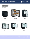
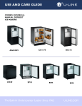
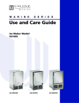
Use and Care Guide
Ice Maker Models:
BI95, BI98, SP18
BI95
BI98
SP18
1 Introduction
Congratulations on your purchase of a U-Line refrigeration product. A pioneer in the field for more than 40 years, U-Line
Corporation is the world’s number one manufacturer of built-in, under-counter, specialty refrigeration and ice making
products. U-Line dedicates 100% of its research and development to these products. The result: U-Line technology
consistently leads the market with innovation, design, depth of product line and performance.
U-Line products are making life more convenient in homes, businesses, and hotels around the world. U-Line supports its
products with a strong dealer network, and its commitment to quality even extends to environmentally safe packaging.
IMPORTANT
READ all of the instructions in this guide completely before operating the unit for the first time.
For future reference, keep this guide in a safe, accessible location. If you need additional information or assistance,
please contact U-Line Corporation directly. Contact information appears on the rear cover of this guide.
If you have a problem with the operation of this product, the SERVICE section of this guide will assist you in quickly
identifying common problems and provide information on possible causes and remedies. If your product needs service,
contact U-Line directly.
Warranty Registration
Your U-Line Corporation Limited Warranty is located on the inside rear cover of this guide. To validate your warranty, the
product and its original purchase date must be registered. A Warranty Registration Card has been included for this
purpose in the package containing this manual. Complete and mail the Warranty Registration Card, or register your
product online at www.U-LineService.com as soon as possible after purchase.
If your product registration is not on file and a request for warranty coverage is received, the date of sale to the U-Line
Selling Dealer or Distributor will be established as the first date of warranty coverage for your product.
Please Record Your Model Information
When you request additional information or service, you will be asked for your products model and serial numbers. You
can find this information on the serial plate located on the upper right or rear wall in the interior of your unit. This
information also appears on the warranty registration card.
2
1
ULIN_0023_A
Figure 1
Please record the model number (Figure 1, 1), serial number (Figure 1, 2), date of purchase, and dealer contact
information for your U-Line product below:
Model Number:
Dealer Name:
_____________________________________________________
_____________________________________________________
Serial Number:
Dealer Address:
_____________________________________________________
_____________________________________________________
Purchase Date:
Dealer Telephone:
_____________________________________________________
_____________________________________________________
2
BI95, BI98, SP18
2 Table of Contents
Introduction ...............................................................................................................................2
Warranty Registration .......................................................................................................2
Please Record Your Model Information ...........................................................................2
Table of Contents .......................................................................................................................3
Safety Precautions ......................................................................................................................5
Safety Alert Definitions .....................................................................................................5
General Precautions ...........................................................................................................5
Product Features ........................................................................................................................6
Origins Ice Maker Models BI95, BI98, SP18 .......................................................................6
Operation ...................................................................................................................................6
Initial Startup .....................................................................................................................6
Ice Harvest Control .............................................................................................................7
Ice Maker ............................................................................................................................7
Normal Operating Sounds .................................................................................................8
Outdoor, Marine and RV Usage ........................................................................................8
Storage, Vacation, Moving ................................................................................................8
Product Disposal .................................................................................................................9
Cleaning and Maintenance .......................................................................................................9
General Cleaning ...............................................................................................................9
Maintenance ....................................................................................................................10
Service .......................................................................................................................................14
Before Calling for Service ................................................................................................14
If Service is Required ........................................................................................................14
Replacement Parts ...........................................................................................................14
Troubleshooting Guide ....................................................................................................15
U-Line Corporation Limited Warranty ....................................................................................19
BI95, BI98, SP18
3
This page intentionally left blank
4
BI95, BI98, SP18
WARNING
3 Safety Precautions
IMPORTANT
PLEASE READ all instructions completely before
attempting to install, operate, or service your unit.
• Proper installation procedures must be followed
if this unit is being initially installed, or is moved
to a new location after being in service. An
INSTALLATION GUIDE for your unit, providing
complete installation information is available
from U-Line Corporation directly, and must be
consulted before any installation is begun. U-Line
contact information appears on the rear cover of
this guide.
• This unit requires connection to a grounded
(three-prong), polarized receptacle that has been
placed by a qualified electrician in accordance
with applicable electrical codes.
Safety Alert Definitions
Safety items throughout this guide are labeled with a
Danger, Warning or Caution based on the risk type:
DANGER
Danger means that failure to follow this safety
statement will result in severe personal injury or
death.
WARNING
Warning means that failure to follow this safety
statement could result in serious personal injury
or death.
CAUTION
Caution means that failure to follow this safety
statement may result in minor or moderate
personal injury, property or equipment damage.
General Precautions
Use this appliance for its intended purpose only and
follow these general precautions along with those listed
throughout this guide:
SHOCK HAZARD - Electrical Grounding Required.
• Never attempt to repair or perform
maintenance on the unit until the electricity
has been disconnected.
• Never remove the round grounding prong from
the plug and never use a two-prong grounding
adapter.
• Altering, cutting of power cord, removal of
power cord, removal of power plug, or direct
wiring can cause serious injury, fire and/or loss
of property and/or life, and will void the
warranty.
• Never use an extension cord to connect power
to the unit.
• Always keep your working area dry.
CAUTION
• Use care when moving and handling the unit. Use
gloves to prevent personal injury from sharp
edges.
• If your model requires defrosting, DO NOT use any
type of heater to defrost. Using a heater to speed
up defrosting can cause personal injury and
damage to the inner lining.
IMPORTANT
• Do not lift unit by door handle.
• Never install or operate the unit behind closed
doors. Be sure front grille is free of obstruction.
Obstructing free air flow can cause the unit to
malfunction and may void the warranty.
• Failure to clean the condenser every three months
can cause the unit to malfunction. This could void
the warranty.
• Allow unit temperature to stabilize for 24 hours
before use.
• If your model requires defrosting, never use an
ice pick or other sharp instrument to help speed
up defrosting. These instruments can puncture
the inner lining or damage the cooling unit.
• Use only genuine U-Line replacement parts.
Imitation parts can damage the unit, affect its
operation or performance and may void the
warranty.
DANGER
RISK OF CHILD ENTRAPMENT. Before you throw away
your old refrigerator or freezer, take off the doors
and leave shelves in place so that children may not
easily climb inside.
BI95, BI98, SP18
5
4 Product Features
5 Operation
Origins Ice Maker
Models BI95, BI98, SP18
1
2
All Origins Ice Makers provide high daily ice production
and storage capabilities, and conserve on water, using
only 2-3/4 gallons (10.4 L) to produce approximately 22 lbs
(10 kg) of ice.
• Model 95 produces up to 23 lbs (10.4 kg) of ice per day
and will store 12 lbs (5.4 kg).
• Model 98 produces up to 25 lbs (11.3 kg) of ice per day
and will store 25 lbs (11.3 kg).
ULIN_0027_A
• Model SP18 produces up to 20 lbs (9 kg) of ice per day
and stores 12 lbs (5.4 kg).
Figure 2
Additional Origins Features
IMPORTANT
• All models feature a clear, removable ice bucket.
• Occasional manual defrosting will be required.
• Models 95 and 98 doors feature an integrated handle,
and will accommodate a custom flat or raised panel to
match surrounding cabinets.
• The Model SP18 door features stainless steel hinges
and fasteners to prevent corrosion, is field-reversible,
and includes a travel pin to keep the door securely
closed.
• All models feature black or white vinyl clad steel
cabinets that provide a rich textured look, and resist
scratching, peeling, and flaking.
Features and specifications are subject to change without
notice.
Proper air flow (Figure 2 - Model 95 and 98 shown)
is required for your unit to operate at its highest
efficiently. A grille, located in the base of the unit,
must not be blocked at any time, or your unit will
not perform as expected.
Initial Startup
All U-Line units are shipped with controls that are preset.
No initial adjustments are required.
IMPORTANT
It is possible that dirt or scale will dislodge in the
water line. Always throw away all ice cubes made
during the first two to three hours of operation.
Model 95 and 98
ON
OFF
The power switch is located behind the front grille. A
small opening in the top of the grille (Figure 2, 2) is
provided to access the switch.
ULIN_0129_A
Figure 3
Depress the ON/OFF switch (Figure 3) as required to turn
the unit on or off.
6
BI95, BI98, SP18
Model SP18
Ice Maker
To turn the unit on or off, press the rocker switch (Figure
3) located in the center of the lower grille.
When the ice bucket is full, the ice making mechanism will
shut off. However, the refrigeration system will continue
to cool and maintain the cube supply.
Ice Harvest Control
Adjustments are not normally needed. The control is
preset at the factory.
IMPORTANT
Do not place cans or bottles in the ice compartment
because they will freeze.
IMPORTANT
Making adjustments may affect the daily ice
production of the unit.
1
2
ULIN_0087_A
Figure 6
ULIN_0027_A
Ice production may be interrupted by raising the bin arm
into an upright and locked position (Figure 6). The unit
will maintain temperature for ice storage.
Figure 4
Models 95 and 98
IMPORTANT
To adjust the Ice Harvest Control:
1. Remove the front grille (one screw) (Figure 4, 1).
C
OL
If you are not intending to use the ice maker and
turn the supply valve off, it is imperative to raise
the bin arm of the ice maker (Figure 6). Failure to
raise the bin arm may result in damage to the water
valve.
Certain sounds are normal during the unit’s operation.
You may hear the compressor or fan motor, the water
valve, or ice dropping into the ice bucket.
DE R
WARNING
ULIN_0131_A
Figure 5
2. Turn the adjusting screw (Figure 5) using a flat tip
screwdriver in a small increment clockwise for a COLDER
setting (slower ice production) or counterclockwise for
a WARMER setting (faster ice production).
3. Replace the front grille (one screw).
Model SP18
Model SP18 has a factory preset Ice Harvest Control that is
optimized for ice production, and is not adjustable.
NEVER use an ice pick, knife or other sharp
instrument to separate cubes. Shake the ice
bucket instead.
During periods of limited usage or high ambient
temperatures, it is common for cubes to fuse together.
Shake the bucket to break apart cubes. If the ice maker is
not used regularly, the ice bucket should be emptied
periodically to ensure fresh cubes.
It is normal for cubes to appear cloudy. This is caused by
air being trapped in the water due to fast freezing. It has
nothing to do with the health, taste or chemical make-up
of the water. It is the same air that is in every glass of
water you drink.
The ice bucket can be removed for emptying and
cleaning. To remove the ice bucket, raise the bin arm and
remove the bucket from the ice compartment. Use the ice
bucket for ice storage only.
BI95, BI98, SP18
7
Normal Operating Sounds
Storage, Vacation, Moving
All models incorporate rigid foam insulated cabinets to
provide high thermal efficiency and maximum sound
reduction for its internal working components. In spite of
this technology, your model may make sounds that are
unfamiliar.
If the unit will not be used for an extended period, or
otherwise stored, follow these steps completely:
Normal operating sounds may be more noticeable
because of the unit’s environment. Hard surfaces such as
cabinets, wood/vinyl/tiled floors and paneled walls have a
tendency to reflect normal appliance operating noises.
Electrical Shock Hazard. Disconnect power before
servicing. Before operating, replace all panels.
Failure to do so may result in death or electrical
shock.
Common refrigeration components, and a brief
description of the normal operating sounds they make,
are listed below. NOTE: Your product may not contain all
of the components listed.
1. Remove all consumable contents from the unit.
WARNING
2. Disconnect power to the unit.
3. Shut off water supply to the unit at the main water
source.
• Compressor: The compressor makes a hum or pulsing
sound that may be heard when it operates.
• Evaporator: Refrigerant flowing through an evaporator
may sound like boiling liquid.
• Condenser Fan: Air moving through a condenser may be
heard.
• Automatic Defrost/Drain Pan: Water may be heard
dripping or running into the drain pan when the unit is in
the defrost cycle.
• Ice dropping into ice bucket.
Outdoor, Marine and RV Usage
Some U-Line models are designed to operate in outdoor,
marine and RV environments. For best performance, keep
the unit out of direct sunlight.
• If the unit will be shut off for five days or more, prop
door open to allow for air circulation and prevent mold
and mildew.
IMPORTANT
If the ambient temperature is expected to drop
below 45°F, turn off and unplug unit, and drain all
water from the unit to prevent freezing damage not
covered by the warranty.
• High ambient temperatures (110°F or higher) may
reduce ice production.
8
IMPORTANT
• If the ambient temperature is expected to drop
below 45°F, turn off and unplug unit, and drain all
water from the unit to prevent freezing damage
not covered by the warranty.
• The use of anti-freeze or other products of this
nature is not necessary and is not recommended.
4. Disconnect the water valve inlet and outlet lines, and
allow them to drain completely.
5. Reconnect power to the unit, and allow it to run for
one hour (minimum) until any remaining ice has been
ejected from the ice maker assembly.
6. Disconnect power to the unit, dry any remaining water
from the ice maker assembly, and reconnect any lines
removed from the water supply valve.
7. Disconnect the power cord from its outlet, and leave it
disconnected until the unit is returned to service.
8. Clean and dry the interior of the cabinet (See CLEANING
AND MAINTENANCE: GENERAL CLEANING).
9. During periods of non-use, the cabinet must remain
open to prevent the formation of mold and mildew.
Open door a minimum of 2" (5 cm) to provide the
necessary ventilation.
BI95, BI98, SP18
Product Disposal
6 Cleaning and Maintenance
If the unit is being removed from service for disposal,
check and obey all Federal, State and/or Local regulations
regarding the disposal and recycling of refrigeration
appliances, and follow these steps completely:
General Cleaning
1. Disconnect power to the unit and unplug the power
cord from its outlet.
Black and White Models:
2. Shut off water supply to the unit at the main water
source and disconnect the supply line to the unit’s water
valve.
DANGER
Exterior Cleaning (As Required)
• Surfaces may be cleaned with a mild detergent and
warm water solution. Do not use solvent-based or
abrasive cleaners. Use a soft sponge and rinse with
clean water. Wipe with a soft, clean towel to prevent
water spotting.
Interior Cleaning (As Required)
RISK OF CHILD ENTRAPEMENT. Before you throw
away your old refrigerator or freezer, take off the
doors and leave shelves in place so that children
may not easily climb inside.
3. Remove the cabinet door if equipped and secure all
interior shelves to the interior of the cabinet using a
heavy duty cloth or package sealing tape.
• Turn unit off. Clean the interior and all removed
components using a mild non-abrasive detergent and
warm water solution applied with a soft sponge or
non-abrasive cloth. Rinse the interior using a soft
sponge and clean water.
• Do not use any solvent-based or abrasive
cleaners. These types of cleaners may transmit
taste to the interior products and damage or
discolor the interior.
BI95, BI98, SP18
9
Maintenance
Proper maintenance of your U-Line product will ensure
efficiency, top performance and long life. The
maintenance intervals listed are based on normal
conditions. You may want to shorten the intervals if you
have pets or other special considerations.
Defrosting
7. Dampen a soft sponge or non-abrasive cloth in clean
water and wipe down the cabinet interior and ice
bucket to remove any detergent residue. Rinse the
sponge or cloth in clean water and repeat as necessary
until the cabinet and ice bucket are clean.
IMPORTANT
DO NOT place ice bucket in dishwasher. Dishwasher
will warp/discolor ice bucket and render it useless.
Manual Defrost Models - Every Two Months
(Minimum)
Condenser Cleaning
WARNING
DO NOT use any type of electrical heating device,
ice pick, knife or other sharp instrument to
defrost; this could damage the inner lining or
refrigeration system and void the warranty.
Interval - Every Three Months
To maintain operational efficiency, keep the front grille
free of dust and lint, and clean the condenser every three
months. Depending on environmental conditions, more
or less frequent cleaning may be necessary.
WARNING
Disconnect electric power to the unit before
cleaning the condenser.
To remove and replace the grille for access to the
condenser fins, follow this procedure:
1
ULIN_0238_A
Figure 8
ULIN_0239_A
1. Disconnect electrical power to the unit.
Figure 7
To defrost:
2. With a standard blade screwdriver or 1/4" nut driver,
remove the grille screw (Figure 8, 1).
1. Turn unit off.
3. Remove the grille.
2. Remove ice bucket and discard ice.
WARNING
3. Place a towel or other absorbent material on bottom of
unit.
4. If you would like, place warm water inside ice bucket.
Then place ice bucket back into unit and close door.
DO NOT touch the condenser fins. The condenser
fins are SHARP and can be easily damaged.
IMPORTANT
5. After approximately one hour, remove ice bucket and
discard water.
DO NOT use any type of cleaner on the condenser
unit.
6. Allow the frost to completely melt naturally. Clean the
interior and ice bucket using a mild non-abrasive
detergent and warm water solution applied with a soft
sponge or non-abrasive cloth. NOTE: DO NOT use any
solvent-based or abrasive cleaners. They will discolor or
damage the interior.
4. Clean the condenser coil using a soft brush with a
“combing” action or vacuum cleaner. Do not touch the
condenser coil.
10
5. Place the two hook-hinges (located on the rear bottom
side of the grille) on the front lip of the unit base.
Swing the grille up into position, aligning the grille and
cabinet screw hole.
BI95, BI98, SP18
6. Insert the grille screw (Figure 8, 1) and tighten. Do not
over-tighten.
7. Reconnect power to the unit.
6. DO NOT remove the inlet screen from the water
solenoid valve. Use a toothbrush to gently clean any
sediment from the inlet screen.
Inlet Screen
7. Re-connect the water supply hose connector (Figure
10, 1) to the water solenoid valve (Figure 10, 2).
Tighten the connector securely.
Interval - Every Twelve Months
The solenoid valve inlet screen must be cleaned at least
once each year as follows:
8. Open the water main supply valve and check for leaks
at the water hose connection. Ensure that the water
supply line is not kinked.
Ice Maker Maintenance
9. Place the two hook-hinges (located on the rear bottom
side of the grille) on the front lip of the unit base.
Swing the grille up into position, aligning the grille and
cabinet screw hole.
WARNING
Disconnect electrical power to the unit before
cleaning the solenoid valve.
Models 95 and 98
10. Insert the grille screw (Figure 9, 1) and tighten. Do not
over-tighten.
1. Disconnect electrical power to the unit.
11. Reconnect power to the unit.
2. Shut off the water at the main supply valve.
Model SP18
1. Disconnect electrical power to the unit.
2. Shut off the water at the main supply valve.
1
3. Pull the unit out to access the back panel.
2
ULIN_0238_A
Figure 9
1
ULIN_0065_A
3. With a standard blade screwdriver or 1/4" nut driver,
remove the grille screw (Figure 9, 1).
4. Remove the grille.
Figure 11
4. Disconnect the hose connector (Figure 11, 1) from the
water solenoid valve (Figure 11, 2).
WARNING
DO NOT touch the condenser fins. The condenser
fins are SHARP and can be easily damaged.
5. DO NOT remove the inlet screen from the water
solenoid valve. Use a toothbrush to gently clean any
sediment from the inlet screen.
6. Re-connect the water supply hose connector (Figure
11, 1) to the water solenoid valve (Figure 11, 2).
Tighten the connector securely.
2
7. Open the water main supply valve and check for leaks
at the water hose connection. Ensure that the water
supply line is not kinked.
8. Reconnect power to the unit before re-installing.
1
ULIN_0064_A
Figure 10
5. Disconnect the hose connector (Figure 10, 1) from the
water solenoid valve (Figure 10, 2).
BI95, BI98, SP18
11
Leveling
Ice Cube Thickness Adjustment
Interval - As Required
The ice cube size may be adjusted by changing the
amount of water injected into the ice maker assembly as
follows:
IMPORTANT
It is extremely important that the unit sits on a
level surface, as it does not have feet levelers. If it
is not level, the ice mold will not fill evenly.
Use a level to check the levelness of the unit from front to
back and from side to side. Level should be placed along
top edge and side edge as shown (Figure 15, 1).
ULIN_0237_A
Figure 12
1. Remove the ice maker assembly cover (Figure 12).
1
ULIN_0309_A
Figure 14
ULIN_0056_A
Figure 13
2. Locate the adjusting screw on the ice maker assembly
control box. The adjusting screw is just below the minus
(-) and plus (+) signs on the control box (Figure 13).
NOTE: Make adjustments in small increments. Too
large of an adjustment could cause the unit to
malfunction.
3. Turn the adjusting screw toward the minus (-) sign
(clockwise) for smaller cubes or toward the plus (+) sign
(counterclockwise) for larger cubes.
4. Install the ice maker assembly cover.
IMPORTANT
Use only genuine U-Line replacement parts. U-Line
ice maker parts are not the same as standard FSP
Whirlpool parts. Using non U-Line parts can reduce
ice rate, cause water to overflow from ice maker
mold, damage the unit and may void the warranty.
12
BI95, BI98, SP18
Door Alignment Check and Adjustment
IMPORTANT
Properly aligned, the door’s gasket should be firmly
in contact with the cabinet all the way around the
door (no gaps). Carefully examine the door’s gasket
to assure that it is firmly in contact with the
cabinet. Also make sure the door gasket is not
pinched on the hinge side of the door.
ULIN_0293_A
Figure 17
2. Remove top hinge from cabinet (three screws) (Figure
17). Hold door to keep it from falling.
3. Lift the door off the bottom hinge.
ULIN_0293_A
Figure 15
1. Loosen (do not remove) top (Figure 15) and bottom
hinge screws.
2. Align door squarely with cabinet.
3. Make sure gasket is firmly in contact with cabinet all
the way around the door (no gaps).
4. Tighten bottom hinge screws.
5. Tighten top hinge screws.
Door Reversal
Figure 18
Depending upon the location of the unit, it may be
desirable to change the side on which the door is
mounted.
4. Remove bottom hinge from cabinet (two screws)
(Figure 18).
To reverse the door mounting, perform the following:
1
ULIN_0137_A
Figure 16
ULIN_0122_A
1. Remove grille (one screw) (Figure 16, 1).
Figure 19
BI95, BI98, SP18
13
5. Remove screws on opposite side of cabinet (Figure 19).
Note that there may be a nut behind one or both
screws on either side.
8. Remove plastic hole plug (Figure 22) from door handle
and relocate on opposite side.
9. Remove pivot screw from top hinge, invert screw and
reinstall pivot screw in top hinge.
ULIN_0144_A
ULIN_0123_A
Figure 23
Figure 20
6. Install hinge on opposite side, bottom of cabinet
(Figure 20). Replace nut on back side where installed.
Align hinge outer edge with cabinet before tightening
screws.
10. Remove three plastic screw plugs (Figure 23) from
hinge holes, top of cabinet, opposite side. Be careful
not to scratch cabinet.
11. Place door on lower hinge pin. Invert and install upper
hinge on door.
1
ULIN_0109_A
ULIN_0145_A
Figure 21
Figure 24
7. Relocate plastic spacer/bushing (Figure 21) on bottom
of door to opposite side, and place door on bottom
hinge pin. Clean out bushing hole in door bottom with
a screwdriver if necessary.
Hinge
Plastic
Plug Hole
Plastic
Plug Hole
12. Fasten upper hinge to unit (three screws) (Figure 24).
Partially tighten screws.
13. Adjust door to assure proper seal. Tighten upper and
lower hinge screws securely.
14. Replace three plastic plugs removed in Step 10 into
holes on top of unit. Replace screws in holes in bottom
of unit on opposite side.
15. Replace the grille.
Screw
Right Side
Door Swing
Left Side
Door Swing
Right Side
Hinge
Invert
Screw
Invert
Hinge
ULIN_0142_A
Figure 22
14
BI95, BI98, SP18
7 Service
Before Calling for Service
If your U-Line product appears to be malfunctioning, read
through the OPERATION section of this guide to ensure
that the function of all controls are clearly understood. If
the malfunction persists, the TROUBLESHOOTING GUIDE
in this guide will assist you in quickly identifying common
problems, and provide information on possible causes and
remedies. Most often, this will resolve the problem
without the need to call for service.
If Service is Required
If you do not understand a troubleshooting remedy, or
your product needs service, contact U-Line Corporation
directly. Contact information appears on the rear cover of
this guide.
You will be asked for your product Model and Serial
Numbers. This information should be recorded inside the
front cover of this guide, following the products original
purchase. It also appears on the Model and Serial number
plate located on the upper right or rear wall of the
interior of your product.
Replacement Parts
When you need replacement parts, always request that
genuine U-Line replacements be used. U-Line products
have been designed and engineered using components
that work efficiently, and provide superior service life and
performance. The use of aftermarket parts or components
may affect the safety, operation, performance or
durability of your product, and may also void its warranty.
BI95, BI98, SP18
15
Troubleshooting Guide
DANGER
ELECTROCUTION HAZARD
Never attempt to repair or perform maintenance on
the unit until the main electrical power has been
disconnected.
Troubleshooting - What to check when problems occur:
PROBLEM
POSSIBLE CAUSE
REMEDY
The unit frosts up.
Unit is manual defrost model.
Models SP18, 95, 98, CO29 and CO75 are manual defrost
(See MAINTENANCE; DEFROSTING).
Door gasket not sealing properly
Adjust door (See MAINTENANCE; DOOR ALIGN, ADJUST,
REVERSE).
High ambient temperatures or
humidity
Defrost unit manually (See MAINTENANCE;
DEFROSTING).
Door left open
Make sure door is closed.
Water is leaking out the back of the
unit.
Water supply connection leaking
Tighten fitting as required.
Ice cubes sticking together
Door gasket not sealing properly
Adjust door (See MAINTENANCE; DOOR ALIGN, ADJUST,
REVERSE).
Infrequent use of cubes
Break apart cubes.
Copper water supply tubing
contacting internal components
Carefully bend tubing away from cabinet and
components.
Certain sounds are normal.
Soft sounds from the fan and water/dropping sounds
from the ice maker will be heard.
Fan blade touching obstruction
(wiring, foam insulation, etc.)
Remove obstruction.
Bin arm locked in upright position
Lower bin arm.
Noise during operation
No ice
Not enough ice
Water leaks into ice bucket.
16
No water to unit
Turn on water or contact plumber.
Control set too cold
Adjust control to a warmer setting (See OPERATION).
Ice cube size too large
Set cube size smaller (See MAINTENANCE; ICE MAKER;
ICE CUBE THICKNESS ADJUST).
Dirty condenser coils
Clean condenser (See MAINTENANCE; CONDENSER
CLEANING).
Water level set too high
Set cube size smaller (See MAINTENANCE; ICE MAKER;
ICE CUBE THICKNESS ADJUST).
BI95, BI98, SP18
This page intentionally left blank
BI95, BI98, SP18
17
This page intentionally left blank
18
BI95, BI98, SP18
U-Line Corporation Limited Warranty
U-Line Corporation warrants each U-Line product to be free from defects in materials and workmanship for a period of
one year from the date of purchase; and warrants the sealed system (consisting of the compressor, the condenser, the
evaporator, the hot gas bypass valve, the dryer and the connecting tubing) in each U-Line product to be free from
defects in materials and workmanship for a period of five years from the date of purchase. During the initial one-year
warranty period for all U-Line products U-Line shall: (1) at U-Lines option, repair any product or replace any part of a
product that breaches this warranty; and (2) for all Marine, RV and Domestic U-Line products sold and serviced in the
United States (including Alaska and Hawaii) and Canada, U-Line shall cover the labor costs incurred in connection with
the replacement of any defective part. During years two through five of the warranty period for the sealed system, ULine shall: (1) repair or replace any part of the sealed system that breaches this warranty; and (2) for all Marine, RV and
Domestic U-Line products sold and serviced in the United States (including Alaska and Hawaii) and Canada, U-Line shall
cover the labor costs incurred in connection with the replacement of any defective part of the sealed system. All other
charges, including transportation charges for replacements under this warranty and labor costs not specifically covered
by this warranty, shall be borne by you. This warranty is extended only to the original purchaser of the U-Line product.
The Registration Card included with the product should be promptly completed by you and mailed back to U-Line or you
can register on-line at www.U-LineService.com.
The following are excluded from this limited warranty: installation charges; damages caused by disasters or acts of God,
such as fire, floods, wind and lightening; damages incurred or resulting from shipping, improper installation,
unauthorized modification, or misuse/abuse of the product; customer education calls; food loss/spoilage; door and water
level adjustments (except during the first 90 days from the date of purchase); defrosting the product; adjusting the
controls; door reversal; or cleaning the condenser.
If a product defect is discovered during the applicable warranty period, you must promptly notify either the dealer from
whom you purchased the product or U-Line at P.O. Box 245040, Milwaukee, Wisconsin 53224 or at 414-354-0300. In no
event shall such notification be received later than 30 days after the expiration of the applicable warranty period. U-Line
may require that defective parts be returned, at your expense, to U-Lines factory in Milwaukee, Wisconsin, for
inspection. Any action by you for breach of warranty must be commenced within one year after the expiration of the
applicable warranty period.
This limited warranty is in lieu of any other warranty, express or implied, including, but not limited to any
implied warranty of merchantability or fitness for a particular purpose; provided however, that to the
extent required by law, implied warranties are included but do not extend beyond the duration of the
express warranty first set forth above. U-Lines sole liability and your exclusive remedy under this warranty
is set forth in the initial paragraph above. U-Line shall have no liability whatsoever for any incidental,
consequential or special damages arising from the sale, use or installation of the product or from any other
cause whatsoever, whether based on warranty (express or implied) or otherwise based on contract, tort or
any other theory of liability.
Some states do not allow limitations on how long an implied warranty lasts or the exclusion or limitation of incidental or
consequential damages, so the above limitations may not apply to you. This warranty gives you specific legal rights, and
you may also have other rights which vary from state to state.
BI95, BI98, SP18
19
For General Inquiries:
P.O. Box 245040
Milwaukee, Wisconsin
53224-9540 U.S.A.
Phone (800) 779-2547
FAX (414) 354-5696
www.U-Line.com
For Service and Parts
Assistance:
Phone (800) 779-2547
(414) 354-0300
FAX (414) 354-5696
Email:
[email protected]
www.U-LineService.com
E-mail:
[email protected]
For more than four decades, U-Line has distinguished itself as the
leader in built-in under-counter ice making, refrigeration and
wine storage appliances.
An INSTALLATION MANUAL for your unit, providing complete
installation information, is available for download at
www.U-Line.com. Information for custom panel inserts per model,
including panel size, and instructions are available by visiting
www.U-Line.com.
When you need replacement parts, always request genuine U-Line
replacements be used. Visit www.U-Line.com to locate a parts
distributor in your area.
U-Line Corporation, located in Milwaukee, WI, is a family operated manufacturer of built-in
undercounter ice makers, Combo® ice maker/refrigerators, Wine Captain® wine storage units,
refrigerators, refrigerated drawers and refrigerator/freezers.
©2006 U-Line Corporation
Publication No. 30098
01/2006 Rev. A