1
 400 Watt
Portable Power Source
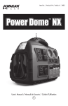
Power Dome
USER’S MANUAL
Compact Generator
KEEP THIS MANUAL FOR FUTURE REFERENCE
Power Dome 400W
USER’S MANUAL - Please read before using this equipment.
Thank you for purchasing the Power Dome 400W Compact Generator by Wagan Tech. With minimal care and proper treatment it will provide years of reliable use. FRONT VIEW
Figure 1 shows the locations of the Compressor, DC Power Outlets, Battery Status/Charging and Work Light
IMPORTANT INFORMATION
BEFORE POWER DOME USE, READ AND UNDERSTAND ALL WARNINGS, CAUTIONS AND NOTES INCLUDED IN THIS MANUAL. FOLLOW INSTRUCTIONS PROVIDED BY YOUR VEHICLE MANUFACTURER AND MANUFACTURER OF DEVICES INTENDED TO BE USED WITH THIS UNIT. KEEP THESE INSTRUCTIONS FOR FUTURE REFERENCE.
MAKE SURE THE POWER DOME IS FULLY CHARGED BEFORE FIRST USE.
MAJOR FEATURES:
1. 600 Amp Jumpstarter with heavy duty cable and clamps.
2. 260 PSI High Flow Air Compressor for inflating tires and accessories
3. Easy-Read analog Pressure Gauge 4. 400 Watt Power Inverter – 1000 watts peak – Two Outlets 115 Volts AC
5. Two 12 Volt Accessory Outlets for powering DC appliance loads to 18 Amps.
6. 1 USB power port
7. Bright Area light – LED type for long battery life.
8. AC Recharging Adapter
9. DC Recharging Adapter (fused)
10. Easy-Read analog voltmeter for checking Battery Status.
11. Jumpstart cable polarity indicator for safety.
2
(fig. 1) BATTERY STATUS
Battery Status provides the user with a current state of charge on the internal battery. It is the user’s responsibility to periodically monitor the battery charge and to recharge the battery after each use. Recharge every three months even if the Power Dome is not used.
• Press and Hold the BATTERY STATUS Button
• The Battery Status Meter (DC Voltmeter) will display the battery voltage.
• Battery status (voltage) is read with charging adapters disconnected.
12.6 VDC and above – Battery is ready for use
12.0 VDC and below – battery needs some charging
Below 10.5 VDC – battery is discharged - charge immediately
3
USER’S MANUAL - Please read before using this equipment.
CHARGING THE POWER DOME
AC Charging
Make sure the supplied AC Charging Adapter is to be powered by the correct voltage. (i.e. 110 VAC or 220 VAC). Only use the AC charging adapter supplied with this unit.
1. Make sure all Power Dome switches are set to OFF.
2. Open the dust cover on the Charging Jack.
3. Make sure all Power Dome switches are set to OFF.
4. Connect the AC Charging Adapter to the AC outlet.
5. Plug the Charging Adapter’s cord into the Power Dome’s Charging Jack.
6. The Charging Indicator will light during the charging process.
7. Initial AC charge can take up to 34 hours.
8. Do not charge for more than 48 hours. 9. After charging the battery, disconnect the adapter from the AC outlet first, then from the charging jack.
10. Replace the dust cover on the charging jack.
NOTE: The Charging Indicator light indicates charging. Press the Charge Status Button for the Voltmeter to show battery voltage and charge status.
DC POWER PORT
DC POWER PORTS (accessory sockets) are located under the Pressure Gauge and the Battery Status Meter (voltmeter). The ports can power a DC load of up to 11 Amps. Overloading the port will result in “tripping” a self-resetting circuit breaker. Removing the overload automatically restores power to the DC Power Ports.
1. Uncover the dust cover from the Power Port.
2. Insert the 12 VDC accessory plug into the Power Port
3. Operate the appliance as usual.
4. After use, disconnect the accessory plug from the Power Port.
5. Replace the Power Port’s dust cover.
6. Recharge the Power Dome as soon as convenient.
WORK LIGHT The Work Light is a cluster of bright LEDs 1. Turn the work light switch (on front panel) to ON position 2. The light will illuminate. 3. Turn OFF the work Light when not in use.
DC Charging in your Vehicle or Boat
USING THE AIR COMPRESSOR
Only use the DC charging adapter supplied with this unit.
NOTE: that the engine must be operating while charging Power Dome.
The Air Compressor Gauge and ON/OFF Switch are located on the front of the Power Dome, The Compressor Air Hose Compartment is located on the rear of the Power Dome.
1. 2. 3. 4. 5. 6. 7. 8. CAUTIONS: Make sure all Power Dome switches are set to OFF.
Open the dust cover on the Charging Jack.
Plug the Charging Adapter’s cord into the Power Dome’s Charging Jack.
Plug the DC Charging Adapter into an accessory outlet (cigarette lighter).
The Charging Indicator will light during the charging process.
Do not charge more than 14 hours using the DC method.
After charging the battery, disconnect the adapter from the accessory socket first, then from the charging jack.
Replace the dust cover on the charging jack.
4
• • Never connect or disconnect the nozzle with the compressor operating.
Before any tire inflation, look for the recommended inflation pressure information on the sidewall of the tire.
INFLATION PROCEDURE
1. 2. 3. 4. 5. Open the Air Hose Compartment door at the rear of the Power Dome and extend the air hose. Position the Power Dome so that you see the front panel.
Make sure nozzle lever is positioned UP (away from the nozzle opening)
Remove the valve cap from the valve stem.
Attach the nozzle to the tire’s valve stem. 5
Power Dome 400W
USER’S MANUAL - Please read before using this equipment.
6. Move the nozzle lever Down to secure the nozzle to the valve stem.
7. Turn compressor switch on to ON position. 8. Monitor the pressure gauge while inflating the tire.
9. When recommended tire pressure has been reached, turn the Compressor OFF.
10. Disconnect hose and replace valve cap.
11. Store the hose in the Air hose Compartment
12. Recharge the Power Dome as soon as convenient.
Figure 2 POWER DOME Rear View
This figure shows the Fuse, Power Inverter’s ON/OFF Switch, two AC Outlets, Jumper Safety Switch and the Compressor Hose Compartment.
DC TO AC POWER INVERTER
The Power Dome’s inverter can operate most AC appliances or a combination of appliances up to 400 watts. Operating time is dependant on the AC load (watts) and the charge and condition of Power Dome’s internal battery. Reduced AC loads and full charge on the battery will result in longer operating time. Be sure to turn off or disconnect any AC appliance not in use. There is a user replaceable 40 amp automotive type fuse to the left of the inverter ON/OFF Switch. This fuse protects the inverter from an unlikely excessive input current. Ordinary overloads will cause the inverter to automatically shut down. Reduce the load and restart the inverter.
USING THE POWER INVERTER
1. 2. 3. 4. 5. 6. 7. 8. 9. Open the AC outlet dust cover.
Connect the AC appliance or appliances to either AC outlet.
Turn on the Inverter using the Inverter’s ON/OFF switch.
If the Inverter Power Indicator LED lights green, the inverter is operating.
Turn on one AC appliance and observe the Power Indicator. If the LED remains green, then turn on the second appliance. If the Power Indicator remains green, then both appliances are operating properly.
After use, remove the appliance plug and close the dust cover.
Recharge Power Dome as soon as convenient.
NOTES: If the Power indicator LED is not lit, then reduce the AC load. If the inverter is still not operating, refer to the troubleshooting table at the end of this User’s Manual. CAUTION: (fig.2)
Some rechargeable devices are equipped with a separate AC charger. These devices will likely operate properly with this inverter. Rechargeable devices that have built-in chargers (see device owner’s manual), may not be operate properly with this type of inverter. The motors of some motorized devices may operate at excessive motor temperature. Abnormally elevated temperature of the motor is an indication that they should not be used with this inverter. Some Televisions and other electronics with sensitive components should be checked to see if they are compatible with modified sine wave (non-sinusoidal) inverters. Check with the appliance manufacturer.
6
7
USER’S MANUAL - Please read before using this equipment.
JUMPSTART WARNINGS
• • • • • • • • • • • • Lead-acid batteries can release explosive gasses. Failure to follow instructions may cause property damage, explosion hazard, and/or personal injury.
Do not smoke while jump starting.
Jumpstart a vehicle or boat in a well ventilated area.
Power Dome is for use with 12 volt systems.
Do not attempt to jumpstart a frozen battery.
Do not wear vinyl clothing when jumpstarting - friction can cause static electricity sparks.
Remove all metal jewelry - this can cause short circuits. Always use safety glasses when jump starting battery acid can cause blindness and/or severe burns.
Never touch red and black clamps together - this can cause, power arcing, and/or explosion.
Do not attempt to jumpstart a frozen battery
After use as jump starter, turn OFF Power Safety Switch. Keep out of reach of children.
Excessive engine cranking can damage the vehicle ‘s starter motor. If the engine fails to start after the recommended number of attempts, discontinue jumpstart procedure and look for other problems that may need to be corrected.
If vehicle to be started has a Positive Grounded System (positive battery terminal is connected to chassis): • Connect negative (-) black clamp to vehicle battery ‘s negative terminal.
• Connect positive (+) red clamp to vehicle chassis or a solid, non-moving, metal vehicle component or body part. DO NOT clamp directly to positive battery terminal or moving part.
JUMPSTARTING
1. 2. 3. 4. 5. 6. 7. Review the Jumpstart Warnings
Make sure all vehicle appliances, lights, radio, etc. are turned OFF.
Make sure the vehicle’s brake is set and the transmission is in “Park”
Make sure all Power Dome switches are OFF.
Securely connect the Red (+) cable Clamp to the vehicle’s Positive (+) battery terminal.
Connect the Black (-) cable Clamp to a non-moving part on the vehicle.
Observe the color of the REVERSE POLARITY LED that is located between the Battery Status and Work Light Switches.
8
8. If the LED is RED – DO NOT TURN ON THE CABLE JUMPER SWITCH • Cable Clamps need to be reversed. • Disconnect the Black Clamp first and then the RED Cable Clamp. • Reconnect and observe the LED. • If the LED is green, turn ON the Jumper Safety Switch.
9. Inside the vehicle, turn on the ignition switch and attempt to start the engine. 10. Crank a maximum of three seconds. If the engine does not start, wait three minutes before the next attempt.
11. After the engine starts, turn OFF the Jumper Safety Switch.
12. Disconnect the Black Clamp first, and then disconnect the Red Clamp.
13. Be sure that the cables and clamps are securely stored. 14. Recharge the Power Dome as soon as convenient.
NOTE: If the engine does not start, there may be a problem other than a discharged battery. Call for service.
USB POWER PORT
Set On/Off safety switch to the “USB port” position. A USB Power Port located underneath the charging jack can power/charge devices that require 5Volts at up to 500mA through the use of a user-supplied cord.
EXTENDING RUN TIME
Extending the run time of Power Dome’s inverter or compressor can be accomplished by powering these functions from a charged external 12 volt automotive-type battery. 1. Follow the procedure for jumpstarting an engine as far as connecting the cables checking for correct battery polarity and turning on the Cable Switch. 2. Now the compressor or inverter can operate for an extended time. • The low voltage protection feature will shut off the inverter when the external and internal batteries discharge to 10 volts.
• The compressor does not have a low battery shut-down feature so the user must check the Battery Status meter on the Power Dome. 3. After The Power Dome is used in an extended run time configuration, turn off the compressor or inverter. 4. Turn off the Cable Switch and store the cables and clamps. 5. Recharge the Power Dome and external battery as soon as possible.
9
Power Dome 400W
USER’S MANUAL - Please read before using this equipment.
TROUBLESHOOTING GUIDE - INVERTER
Trouble Lack of power output
SPECIFICATIONS
Cause Remedy
Sealed Lead Acid Battery - Rechargeable
12-Volt, 18 Amp Hour
Power Dome battery voltage below
10 volts.
Recharge the Power Dome immediately.
Work Light with On/Off Switch
5x LED’s
Compressor
260 PSI Analog Gauge
Excessive current drawn by
appliance being operated.
Reduce load to maximum of 400 watts.
Inverter Output – Modified Sine Wave - Two AC outlets
115 Volts AC 60Hz
Maximum Inverter Output Power
Peak Power
400 Watts – 1000 Watts peak
For a max of 0.3 sec
12V Accessory Outlet
12-volt 11 Amps max
Max AC Charging Time from discharge
34 hours
Max DC Charging Time (engine operating)
14 hours
JumpStart Cables and Clamps
6 Gauge, heavy duty clamps.
42 in length.
1. Turn OFF the device and inverter.
2. Disconnect device.
3. Turn the inverter ON and leave
running for a minimum of 2 minutes.
4. Turn OFF inverter, quickly plug in
device to inverter making sure device
is OFF prior to connection.
5. Turn ON the inverter and the device.
Inverter fuse blown.
Check and replace if necessary. Be sure
any replacement fuse is the same type
and rating.
Excessive voltage drop.
Check Power Dome and recharge
if voltage drops below 10 volts.
Dimensions (LxWxH)
10-3/4 x 8.5 x 12-5/8 in.)
(27.3 x 21.6 x 32.1 cm)
Inverter is overloaded.
Reduce load to maximum of 400 watts.
Weight
17 lbs 13.5 oz (8.1 kg)
Television/Power Tool
will not start
High surge wattage requirement
to start-up.
Toggle the On/Off switch in quick
succession a total of five times. If the
device does not start the device is not
going to work with this type of inverter.
Television Interference
Picture breaking up (snow).
Place the Power Dome as far as possible
from TV, the antenna and the coaxial
cable.
Inverter Power Indicator
is not lit.
TV station may be out or range.
Static/Noise interference
in audio system
Sound system has weak alternating
current shielding.
Do not use inverter with low quality
audio AC filtering system.
Replace audio system with high quality
noise filtering.
10
11
Power Dome 400W
WAGAN Corp. Limited Warranty Registration Form
All WAGAN Corporation products are warranted to the original purchaser of this product.
Warranty Duration: This product is warranted to the original purchaser for a period of one (1) Year from the original purchase date, to be free of defects in material and workmanship. WAGAN Corporation disclaims any liability for consequential damages. In no event will WAGAN Corporation be responsible for any amount of damages beyond the amount paid for the product at retail. In the event of a defective item, please ship the item, prepaid, with a complete explanation of the problem, your name, address and daytime phone number. WAGAN Corporation will, at its option, replaces or repair the defective part. This warranty is void if the product has been damaged by accident, in shipment, unreasonable use, misuse, neglect, improper service, commercial use, repairs by unauthorized personnel or other causes not arising out of defects in materials or workmanship. This warranty is effective only if the product is purchased and operated in the USA and Canada and does not extend to any units which have been used in violation of written instructions furnished.
Warranty Disclaimers: This warranty is in-lieu of all warranties expressed or implied and no representative or person is authorized to assume any other liability in connection with the sale of our products. There shall be no claims for defects or failure of performance or product failure under any theory of tort, contract or commercial law including, but not limited to negligence, gross negligence, strict liability, breach of warranty and breach of contract.
Warranty Performance: During the above one (1) Year warranty period, a product with a defect will be replaced with a comparable model when the product is returned to WAGAN Corporation with an original store receipt. The replacement product will be in warranty for the balance of the one (1) Year warranty period.
• Please activate my limited warranty for WAGAN Corp.
• Enclosed copy of original sales receipt.
Name
Mail Address
Add’l Address
City
State
Zip Code
Item Purchased
Store Name
Date of Purchase
Signature
Date
All WAGAN Corporation Products must be registered within (30) days of purchased to activate
this warranty.
Mail the complete registration form, along with a copy of the original receipt to:
12