1
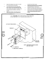
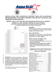
INSTALLATION AND OPERATING INSTRUCTIONS
FOR AQ-1 POWER VENT KIT
DESIGNED FOR
BOSCH 425 HN WATER HEATERS
AQUASTAR 125B WATER HEATERS
INCLUDING AQUASTAR MODELS: 125HX • 125BS • 125X • 125BL
TABLE OF CONTENTS
contents with an AQ-1 power vent
mounting gas pressure switch
mounting linear spillage switch
common setup
locating vent hood (clearances)
mounting power vent motor (clearances)
troubleshooting and maintenance
safety interlock test
AQ-1 wiring diagram
vent hood template
p.1
p.2
p.4
p.6
p.7
p.7
p.9
p.10
p.11
p.12
BTC 719003301 A
AQ-1 Power vent kit
Parts included:
Spillage Switch Kit
1.
2.
3.
185º F linear spillage switch mounted on an
angled bracket and equipped with 36 inch
cables connected to one eyelet terminal
and one 1/4" quick connect terminal
Spillage switch mounting screw
Push on male spade connector, replaces
eyelet terminal from 36 inch spill switch cable.
Vent Hood Kit
1.
2.
3.
4.
4" vent hood: VH1-4
Plastic wall anchors (4)
Sheet metal screws (4)
5" to 4" vent reducer pipe
Vibration Mount Packet
1.
2.
Vibration mounts (2) with nuts and washers
Brackets (2) with nuts and washers
Gas Pressure Switch Packet
1.
2.
3.
4.
Gas pressure switch
Self-tapping mounting screws (4)
Manifold pressure tap fitting with 1/4" compression nut and sleeve
1/4" by 40" aluminum tubing (2)
Power Vent Kit
1.
2.
Power venter (HSUL-1 Series containing
integrated 24v control circuit) including 25
foot control cable with 1/4" quick connect
ends and an HPN 6 foot power cord
Nylon ties
1
Before beginning installation review
required clearances for Water Heater,
Power Vent Motor and Vent Hood
IMPORTANT: FREEZE PREVENTION TO HEATER
Power Vent Kit
In cold climates, ensure the proper closure of the
backdraft flapper when the heater is not running.
If the backdraft flapper does not close properly, cold
air can enter the vent pipe and freeze the heater’s
heat exchanger when not in use. Such damage is not
covered under the water heater's warranty.
CAUTION
1.
Failure to install, maintain and/or operate the
Power Venter in accordance with
manufacturer's instruction may result in
conditions which can produce bodily injury and
property damage.
2.
The Power Venter must be installed by a
qualified installer in accordance with all local
codes or, in their absence, in accordance with
the National Fuel Gas Code (ANSI
Z223.1NFPA #54), the National Electric Code
and The Occupational Health and Safety Act
(OSHA) as applicable.
3.
The Power venter motor shaft must be
mounted horizontally to prevent motor bearing
wear.
4.
Disconnect power supply when making wiring
connections or when working around the fan
blade and motor. Failure to do so may result
in severe personal injury and equipment
damage.
5.
Make certain the power source is adequate for
the fan motor requirements. Do not add the
power venter to a circuit where the total load
is unknown.
AQ-1 Motor is 200 watts- 1.66 amps @ 120vac
Gas Pressure Switch
Remove the gas pressure switch from the bag in the
carton and the brass 1/4" compression nut fitting which
is meant for the burner manifold tap on the heater, not
the inlet tap on the heater's gas inlet pipe (see p. 3,
Fig B). Also remove the four self-tapping screws and
the two sections of 1/4" diameter aluminum tubing from
the master carton.
The gas pressure switch must be mounted in such a
way that the diaphragm is oriented vertically and the
aluminum tubing pieces can easily reach the manifold
pressure test nipple and the burner respectively.
It must not be mounted inside the heater. See
Figure E p.6
When mounting the Gas Pressure Switch: We
recommend mounting the gas pressure switch vertically
against a wall on the lower left side of the water heater.
See Figure E p.6. Because the cabinet cover is three
sided we do not recommend screwing the gas pressure
switch to the left side of it. Instead, mount the gas
pressure switch vertically against a wall on the lower left
side of the water heater. Installed in this manner all
necessary connections will be within reach and there
will be minimal interference when servicing.
Bosch-Aquastar
1.
Follow installation and operating instructions
manual supplied with the water heater.
2.
Before mounting water heater to wall, check
its minimum clearance requirements.
3.
When using an AQ-1 the maximum
horizontal distance from the water heater to the
power vent motor is 100 feet. Subtract 10 feet
for each added elbow. Install power vent
motor as close to the termination as
possible to maintain the water heater's
optimal efficiency.
2
FIGURE B
ROUTE TUBING TO PRESSURE
TAP PORT ON THE
HEATER'S BURNER MANIFOLD
ROUTE TUBING TO BURNER
125B MODEL SHOWN
AREA OR ATMOSPHERIC VENT
FIGURE A
MANIFOLD TAP
PRESSURE TAP-GAUGE PORT
(WHERE HEATER'S BURNER
MANIFOLD PRESSURE CAN BE
MEASURED)
INSTRUCTIONS (SEE DIAGRAMS ABOVE)
1.
Mount gas pressure switch by securing it to
the chosen location with a screw in each one
of the four mounting holes.
a. Remove the brass pressure tap fitting from
the burner manifold of the water heater. This
fitting will not be required for reuse.
2.
Use a tube cutter to make a clean cut (not
crimped) at each end of the two lengths of the
1/4" aluminum tubing. One tube must be long
enough to reach from the fitting marked
"connect to gas valve" to the pressure tap port
on the heater's burner manifold (Not to the
inlet gas pressure port of the water heater
since there will be constant gas pressure
there). The tube must be long enough to enter
the bottom of the water heater front cover and
attach to the burner manifold without difficulty
(See Figure B). The second tube must be long
enough to reach from the gas pressure switch
to the burner area, but not in the pilot flame
area. Allow enough slack for very gradual
bends.
(See Figure A for gas pressure switch ports).
b. Bend one 1/4" aluminum tubing so that it
will run from the gas pressure switch to where
the fitting attaches to the burner manifold.
Make gradual bends - do not crimp the tube.
3.
c. Do not connect to burner manifold, first
assemble the 1/8" NPT male by 1/4"
compression fitting with nut and sleeve to
this end of the aluminum tube. Tighten the
fitting and nut with two wrenches.
d. Separate the joint just made in step 3.c.
ATTENTION - Failure to follow the next series
of instructions may result in breaking a part.
3
Linear Spillage Sensing Switch
e. Hand thread the pressure tap fitting into
the heater's burner manifold. Use a small
amount of an appropriate thread sealant on the
male end of the fitting. Over tightening of
the fitting will break it.
This switch provides a means for safety shut down of the
water heater in the event of flue blockage or power venter
failure. If hot flue gasses spill from the draft hood diverter,
the draft spillage sensing switch will open the pilot safety
circuit and shut off all gas to the water heater. The switch
is normally closed and opens at temperatures greater
than 185º F. It has a manual reset button.
f. Guide the end of the tube into the compression fitting. While using one wrench to
hold back the pressure tap fitting, gently snugup the compression nut with a second wrench.
INSTRUCTIONS
4.
Bend the second piece of aluminum tubing
(from step 2) so that it will reach from the gas
pressure switch through the underneath of the
heater to an area below the burners.
Connect one end of the tube to the fitting
marked "warning" on the gas pressure switch.
The other end of the tubing should now
extend to burner area close to pilot,
position it just below the stainless steel
burners. This tube should not discharge into
the flame nor should it extend above the upper
edge of the burners. This tube vents gas to the
combustion chamber for ignition in case of a
diaphragm failure in the gas pressure switch.
NOTE: The gas pressure switch has a built in
pressure tap marked "gauge port". Use this
tap instead of the heater's manifold tap when
checking manifold pressure. (See Figure A)
1.
The entire length of the copper capillary
sensing tube is heat sensitive. The idea is to
suspend the tube within close proximity of the
heater's draft hood diverter. Note: do not
cut the copper capillary sensing tube.
2.
The linear spill switch should mount in a
location where the tube can extend across the
top of the draft diverters while allowing the
switch cables to reach the ECO.
(See Figure C, page 5)
3.
Route the cables to the ECO switch inside the
water heater keeping the cables out of contact
with hot surfaces.
SAFETY CIRCUIT
The linear spill switch, when wired in series with the
Thermocouple or Pilot Flame Sensor and ECO(s) of the
water heater, form the Safety Circuit.
4
1.
The ECO is mounted on the lower left
outlet water pipe. (See figure C)
a. Remove one lead connecting to ECO
terminal, it does not matter which one is
disconnected.
b. Attach 1/4" quick connect terminal end of
linear spill switch cable to now exposed
terminal of the ECO.
c. Remove the eyelet ended terminal from
the other spill switch cable. Affix the push on
male spade connector, which is provided with
the AQ1, to this spill switch cable.
d. Connect this male spade connector to the
removed lead wire from step 3.a.
FIGURE C
The linear spill switch should be attached to the upper
right-hand side on the draft hood diverter (see figure D),
on the Model 425HN and 125HX the linear spill switch
should be attached to the upper left-hand side of the
draft hood diverter. There are two holes provided for
attachment on this diverter and only the front most hole
should need to be used. With the provided #12 self
tapping sheet metal screw securely mount the spill
switch bracket to the diverter. For ease of access
position it so the reset button faces outward and then
bend the bracket so the switch can stand vertically.
HOT WATER PIPE
ECO
ECO
DISCONNECT EITHER WIRE FROM ECO
TERMINALS ON HOT WATER PIPE. PUSH ON
The copper capillary sensing tube should then be directed to the opposite end of the draft hood diverter, by
laying it in front of the 5" diameter vent pipe opening, and
down the other side of the draft hood diverter.
ONE SPILL SWITCH LEAD CABLE TO ECO
AND OTHER (RETROFIT FIRST) INTO
EITHER WIRE THAT WAS REMOVED.
FIGURE D
CAPILLARY SENSING TUBE
RESET BUTTON
SPILL SWITCH
CABLES
NOTE: ON THE MODEL 425HN AND 125HX, REVERSE THE
DIRECTION OF THE CAPILLARY SENSING TUBE SO THE RESET
BUTTON ASSEMBLY IS ATTACHED TO THE UPPER LEFT-HAND SIDE OF
THE DRAFT HOOD DIVERTER.
5
COMMON SETUP
4" single wall pipe* (galvanized or
stainless steel) or 4" B-type vent*.
5" to 4" vent
reducer pipe
* Single wall vent pipe requires a 6" clearance to
combustibles. B-type vent (double wall) requires a 1"
clearance to combustibles. Use of B-type vent is not
permissible downstream outlet side of the fan motor.
Any additional vent pipe used between the fan motor
and the vent hood must be positive pressure rated with
all seams sealed to prevent leakage. Single wall
galvanized or stainless steel pipe is best.
Vent Hood (see freeze prevention
information on page 2)
Power vent motor
FIGURE E
125B Model shown
Mount gas pressure
switch against wall
See Figure D, page 5 for location of Linear Spillage Switch
6
NOTE: FOLLOW REQUIREMENTS IN FIGURES F & G ON THIS PAGE BEFORE
INSTALLING VENT HOOD, THEN USE TEMPLATE ON PAGE 13 TO CUT HOLE.
"The exit terminals of mechanical vent system shall be
located not less than 7 feet above grade when located
adjacent to a public walkway. The venting system shall
terminate at least 3 feet above any forced air inlet within 10
feet. The venting system shall terminate at least 4 feet
below, 4 feet horizontally from or 1 foot above any door,
window or gravity air inlet into any building."
Also, "The vent terminal shall also not be installed closer
than 3 feet from the inside corner of an L-shaped structure,
or less than 1 foot above grade."
CAUTION
Failure to follow these installation
instructions may violate applicable
national and/or local codes
The vent system must terminate so that proper
clearances are maintained as cited in the National Fuel
Gas Code, ANSI Z223.1
FIGURE F
POWER VENT FAN AND MOTOR
2.
Power venter must be mounted with motor
shaft horizontal to prevent motor bearing
wear.
3.
Power venter housing is single walled. A 6"
clearance from combustible material must be
maintained. (See Figure G)
4.
Position the 5" to 4" reducer pipe on top of the
heater first and then connect a 4" 90º elbow
to begin the horizontal run. Observing this
guideline will help to establish a proper draft.
Code Requirements
Power vent installation must be in accordance with the
following requirements of the National Fuel Gas Code:
Provisions shall be made to interlock the
appliance(s) to prevent the flow of gas to the
main burners when the draft system is not
performing so as to satisfy the operating
requirements of the equipment for safe
performance. (Linear spillage switch: p.4)
FIGURE G
Power vent motor should be installed as close
to the termination of the vent system as
possible to obtain optimal appliance efficiency
and to prevent flue gas leakage.
7
6"
v
6"
v
v
Installation Restrictions
1.
6"
v
v
•
All portions of the vent system under positive
pressure during operation (on the downstream
outlet side of the fan motor) shall use galvanized or stainless steel single wall vent pipe
and be sealed to prevent leakage of flue gases.
v
•
INSTRUCTIONS
(DO NOT BEGIN THESE PROCEDURES
UNTIL VENT HOOD HAS BEEN
INSTALLED)
1.
Remove vibration mounts, nuts and washers
from parts bag. Install on power venter as
shown in (Figure H).
2.
To prevent vibration, securely support power
venter from ceiling or joist using a plumber's
strap or wire fastened to the vibration mounts.
As an alternative means of support, a wall
bracket may be used to support the underside
of the motor. (NOTE: Plumbers strap, wire or
wall bracket must be supplied by installer.)
3.
Connect the power venter outlet to the inner
sleeve of the vent hood. (See page 6 for vent
piping requirements). Use the 4 pre-punched
holes in the outlet collar of the power venter as
a guide to drill 1/8" diameter holes into the vent
pipe. Fasten power venter outlet to the vent
hood inlet (or single wall pipe, depending on if
additional piping is being used between the
venter and the hood) using sheet metal screws.
4.
Any vent pipe connections used after the power
venter (between it and the vent hood) will be
under positive pressure during operation. The
vent pipe must be galvanized or stainless steel
single wall vent pipe. The connections must be
sealed with high temperature silicone sealant or
aluminum vent pipe tape supplied by the
installer.
5.
6.
Support the vent pipe in accordance with vent
manufacturer's instructions. Vent pipe is not
supplied in the power venter package, except
for the 5" to 4" reducer vent pipe in the AQ-1.
Observe the clearances associated with the
class of vent pipe used.
FIGURE H
Installation - Electrical
Install properly sized vent pipe connections
from the power venter inlet to the water heater's
outlet, avoiding elbows wherever possible.
Position the 5" to 4" reducer pipe on top of the
water heater first and then connect a 4" 90º
elbow to begin the horizontal run. Observing
this guideline will help to establish a proper
draft. When using an AQ-1 the maximum
horizontal distance from the water heater to the
power vent motor is 100 feet. Subtract 10 feet
for each added elbow.
8
1.
Route the control cable from the power venter
fan along the ceiling or joists down to the gas
pressure switch, taking care not to come
closer than 6" to the vent pipe or any other
potentially hot surface. In many cases, the
gas supply piping can be used as a routing
path from the ceiling down to the controls,
using the supplied nylon ties to secure the
cable.
2.
Connect the BLUE wire from the jacketed
power vent cable onto the normally open
terminal of the gas pressure switch.
(See Figure I)
FIGURE I
3.
Connect the RED wire from the jacketed cable
onto the common terminal of the gas pressure
switch. (See Figure I)
NOTE: If the distance between the power
venter and the gas pressure switch is
greater than the length of the cable, splice
a section of 2 conductor, PVC sheathed,
105º C thermostat cable to the supplied
cable. Make sure that the colored leads
remain consistent.
TROUBLE-SHOOTING, MAINTENANCE
AND TEST PROCEDURES
5.
Combustion Air Test
1.
Close all doors and windows of the building.
If the water heater is installed in a utility room
or closet, close the entrance door to this room.
Close fireplace dampers.
Vent System Maintenance
The vent system must be inspected at regular 3 month
intervals. Points of inspection are as follows:
1.
2.
Screened opening of the vent hood should be
free from foreign material and cleaned as
necessary.
Check all vent system connections for leakage and reseal where needed. If any vent
pipe shows signs of deterioration, replace
immediately and check new connections for
possible leaks. Reseal using RTV Red HiTemp
Silicone Sealer or equivalent.
Inspect proper closure of the back draft flapper
and correct if it does not close properly after
use.
Gas Pressure Switch Test
1.
Follow the water heater operating instructions
to light the pilot / operate the heater.
2.
Open a hot water outlet. This should energize
the power vent system. Next close the hot
water outlet to de-energize the venter.
3.
Repeat step 2 to assure proper operation.
4.
If power venter does not energize, check that
the gas pressure switch tubes are properly
connected and that the tube ends are not
pinched closed.
Make sure pressure switch is mounted in such
a way that the diaphragm is oriented vertically.
9
2.
Turn on any clothes dryers. Turn on all
exhaust fans, such as a range hood, bath
room exhaust fans and whole house fans, to
maximum speeds. (Do not turn on any fans
used strictly for summer exhausting).
3.
Open a hot water tap to full flow.
4.
Allow all fans and the water heater to operate
for five (5) minutes.
5.
Tripping of the spillage switch circuit (resulting
in shut down of the heater) during the 5 minute
operation indicates an unsafe operating condition. Turn off gas supply to water heater and
DO NOT OPERATE UNTIL UNSAFE VENTING
CONDITION IS INVESTIGATED BY A
PROFESSIONAL CONTRACTOR OR UTILITY
SERVICE PERSONNEL.
6.
Return all windows, doors and fans to their
previous condition of use.
SAFETY INTERLOCK TEST
1.
Open the gas supply to the water heater.
5.
2.
Remove the vent pipe from the vent connector on the top of the water heater.
TROUBLESHOOTING THE POWER VENTER
3.
Block the vent connector with sheet metal or
other noncombustible material.
4.
Turn on the hot water supply to allow the
burner to activate. Hot flue gasses will spill
from the draft diverter momentarily. In less
than three (3) minutes, the linear spillage
switch should trip, opening the electric circuit
to the electromagnet valve and halting the
flow of gas to the burner.
NOTE: If spillage switch does not shut off the
gas, check that you have made the proper
safety circuit connections. If the switch still
does not trip, contact Bosch Water Heating
at 800 642 3111. NOTE: Models
with built in flue gas sensors (mounted on draft
diverter) may cut out operation of the heater
before the spillage switch does. This is not an
error of the spillage switch.
5.
After the burners shut off, turn off hot water
supply and wait 2-3 minutes...then push the
reset button on the linear spillage switch.
6.
Light pilot or operate heater and repeat Safety
Interlock Test, (Step 1-5)
7.
Reconnect the vent pipe to the venting
system when complete.
2.
Verify that there is 115V power provided to the
Power Venter. This can be done by checking
the circuit breaker and electrical connections.
3.
Visually verify that all the connections of the
control cord circuit are intact.
4.
Follow heater installation and operating
instructions for relighting the heater.
Fan Motor runs all the time: Make sure the
pressure tube that connects to the heater is
properly connected to the burner manifold, not
the inlet gas pressure tap at the bottom of the
unit. See Figure B on page 3.
2.
Pilot will not hold when manually lit or
spark automatically with hot water flow:
Check the linear spill switch reset button. If
this corrects the symptom, then either there
was a power outage in the home while the
heater was operating or the heater's flue gases
are not being properly discharged through the
power vent (see CAUTION box below).
CAUTION: If for any reason the system
has shut down during operation, the cause
of the system failure should be investigated
and corrected before resetting the safety
switches and lighting the pilot.
If you have any questions with regard to this installation, please call Bosch Water Heating at 800 642 3111.
In the Event of Pilot/Burner Outage
Push the reset button located in the center of
the linear spillage sensing switch.
1.
If resetting the linear spill switch did not correct
the problem then reference this symptom in the
troubleshooting section of the water heater
manual.
CAUTION: Metal vent pipe and vent
blockage metal will be hot.
1.
Perform the operation circuit test and safety
circuit check. (See Safety Interlock Test)
IMPORTANT: FREEZE PREVENTION TO HEATER
In cold climates, ensure the proper closure of the
backdraft flapper when the heater is not running.
If the backdraft flapper does not close properly, cold
air can enter the vent pipe and freeze the heater’s
heat exchanger when not in use. Such damage is not
covered under the water heater's warranty.
10
S A F E TY I N T E R L O C K D I A G R A M
LINEAR LIMIT
SPILLAGE SENSING
HEATER
SWITCH
ECO
BLACK
185º
MANUAL
RESET
11
1.
2.
3.
Attach this template to the interior of the wall
the Vent Hood will be penetrating.
Insure that proposed vent termination clearances are met before cutting opening through
wall. Using a 1/2" drill bit, drill two pilot holes
where noted on this template. The drill bit must
be long enough to penetrate to the building
exterior.
Attach this template to the building exterior
aligning the pilot holes on the template with
4.
5.
6.
the pilot holes drilled in step 2.
Using a reciprocating saw, cut a hole through
the building siding, wall board, etc., following
the appropriate lines of this template.
Slide the vent hood through the opening and
fasten to exterior wall using provided screws.
Once Power Venter is completely installed and
secured, apply a bead of exterior rated caulk
between Vent Hood flange and exterior of
building.
VH1-4 (SQUARE) VENT HOOD INSTALLATION TEMPLATE
ACTUAL HOOD SIZE 7½" X 7½" (ROUGH IN SHOULD BE 8" X 8")
CUT HOLE THROUGH WALL
TEMPLATE
PILOT
HOLE
PILOT
HOLE
BUILDING
EXTERIOR
NOTE: HARDWARE SHOWN INCLUDED
WITH VENT HOOD
WASHER (4)
SHEET METAL SCREW (4)
12