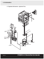
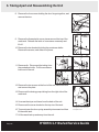
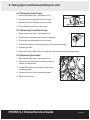
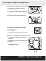
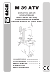
1
®
&
P0
P1
P2
P3
P4
®
Rinse and hold
Regular wash
Regular wash and dry
Heavy duty wash
Heavy duty wash and dry
• Service Guide
• Manuel maintenance
Website:
• Wartungsanleitung
www.yourCEBA.com
Customer
Service: di manutenzione
• Manuale
Phone: 1-916-335-6113
Email: [email protected]
Product Information and Technical Support:
Phone: 509-747-5027
email: [email protected]
www.scican.com
HYDRIM L110wd / HYDRIM L110w Service Guide 96-108019 Rev 3.0
Copyright 2005 SciCan. All rights reserved.
Contents
1. Introduction . . . . . . . . . . . . . . . . . . . . . . 5
1.1
1.2
1.3
1.4
1.5
1.6
Overview . . . . . . . . . . . . . . . . . . . . . . . . . . . . . . . . . . .5
Specifications . . . . . . . . . . . . . . . . . . . . . . . . . . . . . .8
Safety Information . . . . . . . . . . . . . . . . . . . . . . . . . .9
Hardware Specifications . . . . . . . . . . . . . . . . . .11
Shipping Instructions . . . . . . . . . . . . . . . . . . . . . .11
Contact Information . . . . . . . . . . . . . . . . . . . . . . . .11
2. Installation . . . . . . . . . . . . . . . . . . . . . . 12
2.1
2.2
2.3
2.4
2.5
2.6
2.7
2.8
Suggested Installation Configurations . . . . . .12
Water Connections . . . . . . . . . . . . . . . . . . . . . . . . .12
Water Softener . . . . . . . . . . . . . . . . . . . . . . . . . . . .13
Drainage . . . . . . . . . . . . . . . . . . . . . . . . . . . . . . . . . .14
Printer . . . . . . . . . . . . . . . . . . . . . . . . . . . . . . . . . . . .14
Set up and Installation Tips . . . . . . . . . . . . . . . . .15
Optional Installation Configurations . . . . . . . . .16
Controller Software Functions . . . . . . . . . . .17
3. Routine Maintenance . . . . . . . . . . . . . .19
6. Taking Apart and
Reassembling the Unit . . . . . . . . . . . . .27
6.1
6.2
6.3
6.4
6.5
6.6
6.7
6.8
6.9
6.10
Removing the Cleaning Solution . . . . . . . . . . . .27
Removing the Back Cover . . . . . . . . . . . . . . . . . .27
Removing the Top Cover . . . . . . . . . . . . . . . . . . .27
Removing the Kick Plate . . . . . . . . . . . . . . . . . . .28
Removing the Left Side Panel . . . . . . . . . . . . . .28
Removing the Right Side Panel . . . . . . . . . . . . .28
Removing Door Panel . . . . . . . . . . . . . . . . . . . . .28
Removing the Dosing Pump . . . . . . . . . . . . . . . .28
Removing the Dryer . . . . . . . . . . . . . . . . . . . . . . .29
6.9.1 Removing Air Filter . . . . . . . . . . . . . . . . . . .29
6.9.2 Removing Dryer Blower Brushes . . . . . .29
Removing the Control Panel Fascia . . . . . . . .29
6.10.1 Removing the On / Off Switch . . . . . . . .30
6.10.2 Removing the Door Lock . . . . . . . . . . . .30
6.10.3 Removing the Master Controller . . . . .30
Removing the Slave Controller . . . . . . . . . . . . .30
Removing Wash Tank . . . . . . . . . . . . . . . . . . . . . .31
Removing Drain Pump . . . . . . . . . . . . . . . . . . . . .33
Removing Circulation Pump . . . . . . . . . . . . . . . .33
Removing the Heater . . . . . . . . . . . . . . . . . .33
Removing the Hot and Cold Inlet Valve . . . . . .34
Removing the Temperature Sensor . . . . . . .34
Removing the Condenser . . . . . . . . . . . . . .34
4.1 Hydraulic Schematic . . . . . . . . . . . . . . . . . . . . . . .21
4.2 Electrical . . . . . . . . . . . . . . . . . . . . . . . . . . . . . . . . . .23
6.11
6.12
6.13
6.14
6.15
6.16
6.17
6.18
5. Troubleshooting . . . . . . . . . . . . . . . . . .24
7. Parts . . . . . . . . . . . . . . . . . . . . . . . . . . .35
3.1
3.2
3.3
3.4
Filters . . . . . . . . . . . . . . . . . . . . . . . . . . . . . . . . . . . . .19
Leveling the unit . . . . . . . . . . . . . . . . . . . . . . . . . . .19
Wash Arms . . . . . . . . . . . . . . . . . . . . . . . . . . . . . . .19
Hoses . . . . . . . . . . . . . . . . . . . . . . . . . . . . . . . . . . . .20
4. Schematics . . . . . . . . . . . . . . . . . . . . . .21
5.1
5.2
5.3
5.4
5.5
Primary Assessment . . . . . . . . . . . . . . . . . . . . . . .24
Power On Problems . . . . . . . . . . . . . . . . . . . . . . .24
Controller Problems . . . . . . . . . . . . . . . . . . . . . . .24
Fault Codes . . . . . . . . . . . . . . . . . . . . . . . . . . . . . . .25
Hydraulic Overview . . . . . . . . . . . . . . . . . . . . . . . .26
Hydrim L110wd
Copyright 2005 SciCan. All rights reserved.
HYDRIM is a registered trademark of SciCan, Division of Lux and
Zwingenberger.
Hydrim L110w
Manufactured by:
SciCan
Distributed by:
SciCan, Division of Lux and Zwingenberger
Toronto, Ontario, Canada
Phone: (416) 445-1600
Fax : (416) 446-2727
1440 Don Mills Road,Toronto,
ON M3B 3P9 CANADA
Phone:
(416) 445-1600
Fax:
(416) 445-2727
Toll free:
1-800-667-7733
Manufactured by / EU Representative
BHT Hygienetechnik GmbH
Messerschmittstr. 11,
D-86368 Gersthofen
GERMANY
Phone:
49-0821-278-930
Fax:
49-0821-78-40-99
SciCan Inc.
SciCan Medtech
For all service and repair inquiries:
In Canada:
1-800-870-7777
In The United States:
1-800-572-1211
Alpenstrasse 16, 2300 Zug, Switzerland
Phone: (41-41) 727-70-27
Fax:
(41-41) 727-70-29
500 Business Center Drive,Pittsburgh, PA 15205 USA
Phone:
(412) 494-0181
Fax:
(412) 494-4794
Toll free:
1-800-572-1211
Email (Service and Repair): [email protected]
Email: [email protected]
HYDRIM L110w/wd Service Guide
Page 1
Sommaire
1. Introduction . . . . . . . . . . . . . . . . . . . . . 38
1.1
1.2
1.3
1.4
1.5
1.6
Généralités . . . . . . . . . . . . . . . . . . . . . . . . . . . . . . .38
Spécifications . . . . . . . . . . . . . . . . . . . . . . . . . . . . .42
Informations de sécurité . . . . . . . . . . . . . . . . . . .42
Eléments de fixation . . . . . . . . . . . . . . . . . . . . . .44
Instructions d’expédition . . . . . . . . . . . . . . . . . . .44
Contacts . . . . . . . . . . . . . . . . . . . . . . . . . . . . . . . . . .44
2. Installation . . . . . . . . . . . . . . . . . . . . . . 45
2.1 Suggestions de configurations
d’installation . . . . . . . . . . . . . . . . . . . . . . . . . . . . . . .45
2.2 Prise d’eau . . . . . . . . . . . . . . . . . . . . . . . . . . . . . . . .45
2.3 Adoucisseur d’eau . . . . . . . . . . . . . . . . . . . . . . . . .46
2.4 Vidange . . . . . . . . . . . . . . . . . . . . . . . . . . . . . . . . . . .47
2.5 Imprimante . . . . . . . . . . . . . . . . . . . . . . . . . . . . . . . .47
2.6 Conseils pour le montage et l’installation . . . .48
2.7 Autres configurations d’installation . . . . . . . . .49
2.8 Fonctions du logiciel de commande . . . . . . .50
3. Entretien de routine . . . . . . . . . . . . . . .53
3.1
3.2
3.3
3.4
Filtres . . . . . . . . . . . . . . . . . . . . . . . . . . . . . . . . . . . . .53
Mise de niveau de l’appareil . . . . . . . . . . . . . . . .53
Bras de lavage . . . . . . . . . . . . . . . . . . . . . . . . . . . . .53
Flexibles . . . . . . . . . . . . . . . . . . . . . . . . . . . . . . . . . .54
4. Schémas . . . . . . . . . . . . . . . . . . . . . . . .55
4.1 Système hydraulique . . . . . . . . . . . . . . . . . . . . . .55
4.2 Système électrique . . . . . . . . . . . . . . . . . . . . . . . .57
5. Dépannage . . . . . . . . . . . . . . . . . . . . . .58
5.1
5.2
5.3
5.4
5.5
Premières mesures . . . . . . . . . . . . . . . . . . . . . . . .58
Problèmes de mise en marche . . . . . . . . . . . . .58
Problèmes de commande . . . . . . . . . . . . . . . . . .58
Codes de défaut . . . . . . . . . . . . . . . . . . . . . . . . . . .59
Système hydraulique . . . . . . . . . . . . . . . . . . . . . .60
Hydrim L110wd
Distributed by:
SciCan, Division of Lux and Zwingenberger
Toronto, Ontario, M3B 3P9 Canada
Phone: (416) 445-1600
Fax : (416) 446-2727
Manufactured by / EU Representative
BHT Hygienetechnik GmbH
Messerschmittstr. 11,
D-86368 Gersthofen
GERMANY
Phone:
49-0821-278-930
Fax:
49-0821-78-40-99
SciCan Medtech
Alpenstrasse 16, 2300 Zug, Switzerland
Phone: (41-41) 727-70-27
Fax:
(41-41) 727-70-29
Page 2
6. Démontage et remontage
de l’appareil . . . . . . . . . . . . . . . . . . . . .61
6.1 Démonter le réservoir de
solution de lavage . . . . . . . . . . . . . . . . . . . . . . . . .61
6.2 Démonter le panneau arrière . . . . . . . . . . . . . . .61
6.3 Démonter le panneau supérieur . . . . . . . . . . . .61
6.4 Démonter la plinthe . . . . . . . . . . . . . . . . . . . . . . . .62
6.5 Démonter le panneau latéral gauche . . . . . . .62
6.6 Démonter le panneau latéral droite . . . . . . . . .62
6.7 Démonter le panneau de la porte . . . . . . . . . . .62
6.8 Démonter la pompe de dosage . . . . . . . . . . . . .62
6.9 Démonter le sécheur . . . . . . . . . . . . . . . . . . . . . . .63
6.9.1 Démonter le filtre à air . . . . . . . . . . . . . . . . .63
6.9.2 Démonter les brosses de
la soufflante du sécheur . . . . . . . . . . . . . . .63
6.10 Démonter le revêtement du panneau
de commande . . . . . . . . . . . . . . . . . . . . . . . . . . . . .63
6.10.1 Démonter l’interrupteur principal . . . . .63
6.10.2 Démonter le verrouillage de
la porte . . . . . . . . . . . . . . . . . . . . . . . . . . . . .64
6.10.3 Démonter la commande principale . . .64
6.11 Démonter la commande secondaire . . . . . . . .64
6.12 Démonter la chambre de lavage . . . . . . . . . . . .65
6.13 Démonter la pompe de vidange . . . . . . . . . . . .67
6.14 Démonter la pompe de circulation . . . . . . . . . .67
6.15 Démonter le chauffage . . . . . . . . . . . . . . . .67
6.16 Démonter les valves d’entrée d’eau
froide et d’eau chaude . . . . . . . . . . . . . . . . .68
6.17 Démonter le capteur de température . . . . . .68
6.18 Démonter le condenseur . . . . . . . . . . . . . . .68
7. Pièces . . . . . . . . . . . . . . . . . . . . . . . . . .69
Copyright 2005 SciCan. Tous droits réservés.
HYDRIM est une marque déposée de SciCan, Division of Lux and
Zwingenberger.
Hydrim L110w
Manufactured by:
SciCan
1440 Don Mills Road,Toronto,
ON M3B 3P9 CANADA
Phone:
(416) 445-1600
Fax:
(416) 445-2727
Toll free:
1-800-667-7733
SciCan Inc.
500 Business Center Drive,Pittsburgh, PA 15205 USA
Phone:
(412) 494-0181
Fax:
(412) 494-4794
Toll free:
1-800-572-1211
Email (Service and Repair): [email protected]
Email: [email protected]
For all service and repair inquiries:
In Canada:
1-800-870-7777
In The United States:
1-800-572-1211
HYDRIM L110w/wd Service Guide
Inhaltsverzeichnis
1. Einleitung . . . . . . . . . . . . . . . . . . . . . . . . .72
1.1 Überblick . . . . . . . . . . . . . . . . . . . . . . . . . . . .72
1.2 Technische Daten . . . . . . . . . . . . . . . . . . . . .75
1.3 Sicherheitsmaßnahmen . . . . . . . . . . . . . . . . .76
1.4 Angaben zu Verbindungselementen . . . . . . .78
1.5 Transporthinweise . . . . . . . . . . . . . . . . . . . . .78
1.6 Ansprechpartner . . . . . . . . . . . . . . . . . . . . . .78
2. Installation . . . . . . . . . . . . . . . . . . . . . . . .79
2.1 Vorschläge für die Einbaukonfiguration . . . . .79
2.2 Wasseranschluss . . . . . . . . . . . . . . . . . . . . . .79
2.3 Wasserenthärter . . . . . . . . . . . . . . . . . . . . . .80
2.4 Wasserablauf . . . . . . . . . . . . . . . . . . . . . . . . .81
2.5 Drucker . . . . . . . . . . . . . . . . . . . . . . . . . . . . .81
2.6 Aufstell- und Installationshinweise . . . . . . . . .82
2.7 Aufstellungsmöglichkeiten . . . . . . . . . . . . . . .83
2.8 Funktionen der Steuerungs-Software . . . . . .84
3. Routinewartung . . . . . . . . . . . . . . . . . . .87
3.1 Siebe . . . . . . . . . . . . . . . . . . . . . . . . . . . . . . .87
3.2 Justieren des Geräts . . . . . . . . . . . . . . . . . . .87
3.3 Sprüharme . . . . . . . . . . . . . . . . . . . . . . . . . . .87
3.4 Schläuche . . . . . . . . . . . . . . . . . . . . . . . . . . .88
4. Schematische Darstellungen . . . . . . . . .89
4.1 Schematische Darstellung Wasserkreislauf . .89
4.2 Schaltbild . . . . . . . . . . . . . . . . . . . . . . . . . . . .91
5. Fehlersuche . . . . . . . . . . . . . . . . . . . . . . .92
5.1 Als Erstes durchzuführende Prüfungen . . . . .92
5.2 Probleme beim Einschalten . . . . . . . . . . . . . .92
5.3 Probleme mit der Steuerung . . . . . . . . . . . . .92
5.4 Fehlercodes . . . . . . . . . . . . . . . . . . . . . . . . . .93
5.5 Übersicht Wasserkreislauf . . . . . . . . . . . . . . .94
6. Demontage und Wiederzusammenbau
des Geräts . . . . . . . . . . . . . . . . . . . . . . . .95
6.1 Reinigungslösung herausnehmen . . . . . . . . .95
6.2 Rückwand abnehmen . . . . . . . . . . . . . . . . . .95
6.3 Obere Abdeckung abnehmen . . . . . . . . . . . .95
6.4 Fußleiste abnehmen . . . . . . . . . . . . . . . . . . .96
6.5 Linke Seitenwand abnehmen . . . . . . . . . . . . .96
6.6 Rechte Seitenwand abnehmen . . . . . . . . . . .96
6.7 Türverkleidung abnehmen . . . . . . . . . . . . . . .96
6.8 Dosierpumpe ausbauen . . . . . . . . . . . . . . . . .96
6.9 Trockner ausbauen . . . . . . . . . . . . . . . . . . . .97
6.9.1 Luftfilter ausbauen . . . . . . . . . . . . . . .97
6.9.2 Bürsten des Trocknergebläses
herausnehmen . . . . . . . . . . . . . . . . . .97
6.10 Verkleidung des Bedienfeldes entfernen . . .97
6.10.1 Ein- / Aus-Schalter ausbauen . . . . . .98
6.10.2 Türverriegelung ausbauen . . . . . . . .98
6.10.3 Hauptsteuergerät ausbauen . . . . . . .98
6.11 Nebensteuergerät ausbauen . . . . . . . . . . . .98
6.12 Spülkammer ausbauen . . . . . . . . . . . . . . . .99
6.13 Entwässerungspumpe ausbauen . . . . . . .101
6.14 Umwälzpumpe ausbauen . . . . . . . . . . . . .101
6.15 Heizung ausbauen . . . . . . . . . . . . . . . . . . .101
6.16 Einlassventile für Kaltwasser
und Warmwasser ausbauen . . . . . . . . . . .102
6.17 Temperaturfühler ausbauen . . . . . . . . . . . .102
6.18 Kondensator ausbauen (Hydrim L110wd) .102
7. Teile . . . . . . . . . . . . . . . . . . . . . . . . . . . .103
Copyright 2005 SciCan. Alle Rechte vorbehalten.
HYDRIM ist ein eingetragenes Warenzeichen von SciCan, Division of
Lux and Zwingenberger.
Hydrim L110wd
Distributed by:
SciCan, Division of Lux and Zwingenberger
Toronto, Ontario, Canada
Phone: (416) 445-1600
Fax : (416) 446-2727
Manufactured by / EU Representative
BHT Hygienetechnik GmbH
Messerschmittstr. 11,
D-86368 Gersthofen
GERMANY
Phone:
49-0821-278-930
Fax:
49-0821-78-40-99
SciCan Medtech
Alpenstrasse 16, 2300 Zug, Switzerland
Phone: (41-41) 727-70-27
Fax:
(41-41) 727-70-29
HYDRIM L110w/wd Service Guide
Page 3
Indice
1. Introduzione . . . . . . . . . . . . . . . . . . . . .106
1.1 Sommario . . . . . . . . . . . . . . . . . . . . . . . . . .106
1.2 Caratteristiche tecniche . . . . . . . . . . . . . . . .109
1.3 Misure di sicurezza . . . . . . . . . . . . . . . . . . . .110
1.4 Specifica degli elementi di collegamento . . .112
1.5 Istruzioni sulla spedizione . . . . . . . . . . . . . .112
1.6 Interlocutori . . . . . . . . . . . . . . . . . . . . . . . . .112
2. Installazione . . . . . . . . . . . . . . . . . . . . .113
2.1 Configurazioni d’installazione consigliate . . .113
2.2 Allacciamento dell’acqua . . . . . . . . . . . . . . .113
2.3 Addolcitore d’acqua . . . . . . . . . . . . . . . . . . .114
2.4 Scarico dell’acqua . . . . . . . . . . . . . . . . . . . .115
2.5 Stampante . . . . . . . . . . . . . . . . . . . . . . . . . .115
2.6 Indicazioni per l’installazione . . . . . . . . . . . .116
2.7 Possibilità di installazione . . . . . . . . . . . . . . .117
2.8 Funzioni del software di controllo . . . . . . . . .118
3. Manutenzione ordinaria . . . . . . . . . . . .121
3.1 Filtri . . . . . . . . . . . . . . . . . . . . . . . . . . . . . . .121
3.2 Livellamento della lavastrumenti . . . . . . . . .121
3.3 Bracci di lavaggio . . . . . . . . . . . . . . . . . . . . .121
3.4 Tubi flessibili . . . . . . . . . . . . . . . . . . . . . . . .122
4. Schemi . . . . . . . . . . . . . . . . . . . . . . . . . .123
4.1 Schema della circolazione d’acqua –
Hydrim L110wd . . . . . . . . . . . . . . . . . . . . . .124
4.2 Schema elettrico . . . . . . . . . . . . . . . . . . . . .125
5. Eliminazione dei guasti . . . . . . . . . . . . .126
5.1 Primi controlli da eseguire . . . . . . . . . . . . . .126
5.2 Problemi all’accensione . . . . . . . . . . . . . . . .126
5.3 Problemi del dispositivo di controllo . . . . . . .126
5.4 Codici di guasto . . . . . . . . . . . . . . . . . . . . . .127
5.5 Panoramica della circolazione d’acqua . . . .128
6. Smontaggio e riassemblaggio
della lavastrumenti . . . . . . . . . . . . . . . .129
6.1 Estrarre la soluzione detergente . . . . . . . . .129
6.2 Rimuovere la copertura posteriore . . . . . . . .129
6.3 Rimuovere la copertura superiore . . . . . . . .129
6.4 Rimuovere lo zoccolo . . . . . . . . . . . . . . . . . .130
6.5 Rimuovere il pannello laterale sinistro . . . . .130
6.6 Rimuovere il pannello laterale destro . . . . . .130
6.7 Rimuovere il pannello dello sportello . . . . . .130
6.8 Smontare la pompa di dosaggio . . . . . . . . . .130
6.9 Smontare l’asciugatrice . . . . . . . . . . . . . . . .131
6.9.1 Smontare il filtro dell’aria . . . . . . . . . .131
6.9.2 Rimuovere le spazzole del soffiante
dell’asciugatrice . . . . . . . . . . . . . . . .131
6.10 Rimuovere la copertura del pannello
di comando . . . . . . . . . . . . . . . . . . . . . . . .131
6.10.1 Smontare l’interruttore On / Off . . . .132
6.10.2 Smontare il dispositivo di chiusura
dello sportello . . . . . . . . . . . . . . . . .132
6.10.3 Smontare il dispositivo di controllo
principale (Master) . . . . . . . . . . . . .132
6.11 Smontare il dispositivo di controllo
ausiliario (Slave) . . . . . . . . . . . . . . . . . . . .132
6.12 Smontare la camera di lavaggio . . . . . . . . .133
6.13 Smontare la pompa di scarico . . . . . . . . . . .133
6.14 Smontare la pompa di circolazione . . . . . . .133
6.15 Smontare il riscaldamento . . . . . . . . . . . . .133
6.16 Smontare le valvole di aspirazione
per l’acqua fredda e calda . . . . . . . . . . . . .136
6.17 Smontare la sonda termica . . . . . . . . . . . .136
6.18 Smontare il condensatore
(Hydrim L110wd) . . . . . . . . . . . . . . . . . . . .136
7. Componenti . . . . . . . . . . . . . . . . . . . . . .137
Hydrim L110wd
Distributed by:
SciCan, Division of Lux and Zwingenberger
Toronto, Ontario, Canada
Phone: (416) 445-1600
Fax : (416) 446-2727
Manufactured by / EU Representative
BHT Hygienetechnik GmbH
Messerschmittstr. 11,
D-86368 Gersthofen
GERMANY
Phone:
49-0821-278-930
Fax:
49-0821-78-40-99
SciCan Medtech
Alpenstrasse 16, 2300 Zug, Switzerland
Phone: (41-41) 727-70-27
Fax:
(41-41) 727-70-29
Page 4
HYDRIM L110w/wd Service Guide
1. Introduction
P0
P1
P2
P3
P4
Rinse and
hold
Regular wash
Regular wash
Heavy duty
Heavy duty
and dry
wash
wash and dry
Figure 1
1.1 Overview
This guide provides instructions for the servicing and repair of the HYDRIM ® L110wd
washer disinfector and the HYDRIM ® L110w instrument washer. Every attempt has been
made to provide accurate, detailed instructions.
All servicing of the Hydrim L110wd and Hydrim L110w should be done by certified
personnel only. All local, provincial, state, and national regulations regarding the servicing
of the class of device and safety requirements must be observed.
Do not permit any person other than certified personnel to supply parts for, service,
or maintain a Hydrim L110wd or Hydrim L110w. SciCan shall not be liable for incidental,
special, or consequential damages caused by any maintenance or services performed on
the Hydrim L110wd or Hydrim L110w by a third party, including lost profits, any
commercial loss, economic loss, or loss arising from personal injury.
Pay close attention to the symbols that appear in the margins.
The following symbols indicate:
a potential hazard to the operator.
a situation or circumstance which may lead to a mechanical failure.
important information.
HYDRIM L110w/wd Service Guide
Page 5
1. Introduction
The Hydrim L110wd and Hydrim L110w are designed to complement the STATIM family of
autoclaves by quickly and hygienically preparing soiled instruments for sterilization.
The Hydrim L110wd and Hydrim L110w work like most domestic dishwashers. The
operator loads the instruments, closes the door, and selects the wash cycle. Both the
Hydrim L110wd and Hydrim L110w automatically dispense cleaning solution via a dosing
mechanism. The operator is responsible for adding water softening salt, adding rinse aid
(if necessary), cleaning the filters, and replacing the cleaning solution container
when necessary.
Hydrim L110wd washer disinfector:
The program duration and consumption details are shown in the chart below:
Program
Wash
Temperature
30˚C / 5 min.
Rinse / Disinfection
Temperature
–
Total Time*
Water Usage
8 minutes
4L
65˚C / 3 min
38 minutes
19 L
P3 Wash with 80˚C
rinse
50˚C / 5 min.
80˚C / 10 min.
64 minutes
19 L
P4 Wash with 93˚C
disinfection
50˚C / 5 min.
93˚C / 10 min
69 minutes
19 L
–
10 minutes
–
P1 Pre-wash
P2 Wash with 65˚C
rinse
50˚C / 5 min.
Air Drying
–
* Actual cycle time will vary depending on incoming water temperature and pressure
NOTE: For ophthalmology use, an additional rinse is required which lengthens P2, P3,
and P4 by 11 minutes, and increases water consumption by 8 litres. See section 2.8 for
instructions how to program the additional rinse.
Page 6
HYDRIM L110w/wd Service Guide
1. Introduction
The Hydrim L110w instrument washer:
The program duration and consumption details are shown in the chart below:
Program
Wash
Temperature
Time*
Water Usage
P0 - Rinse and
Hold
P1 - Regular wash
P2 - Regular wash
with dry
P3 - Heavy duty
wash
P4 - Heavy duty
wash with dry
30˚C / 86˚F
8 minutes
4 L / 1 gallon
50˚C / 122˚F
50˚C / 122˚F
20 minutes
30 minutes
16L / 4 gallons
16L / 4 gallons
50˚C / 122˚F
30 minutes
19L / 5 gallons
50˚C / 122˚F
40 minutes
19L / 5 gallons
* Actual cycle time will vary depending on incoming water temperature and pressure
Website:
www.yourCEBA.com
Customer Service:
Phone: 1-916-335-6113
Email: [email protected]
Product Information and Technical Support:
Phone: 509-747-5027
email: [email protected]
HYDRIM L110w/wd Service Guide
Page 7
1. Introduction
1.2 Specifications
Hydrim L110wd washer disinfector:
Dimensions:
Height (free-standing)
Height (built-in)
Width
Depth
Depth with Door Open
Weight
Running Noise
Cold Water Connection
Pressure
Waste Water connection
Page 8
Wash Temperature
Cold Rinse
Thermal Disinfection
850 mm
810 mm
600 mm
600 mm
1143 mm
85 kg
58 dB wash 78 dB dry
3/4" - 14 NPSM
0.3 - 10 bar (gauge)
direct connection to drain according
to local code requirements
50 - 60˚C
< 30˚C
93˚C
Electrical Consumption:
Europe
North America
Rated Load
220 - 240 V 50 Hz 10-16 A
220 - 240 V 60 Hz 15A
2.5 kW
Other:
Equipment Pollution Degree
Equipment Installation Category
Maximum relative humidity
Maximum altitude
Maximum ambient temperature
IP
2
II
20 - 80 %
1600 m
30˚C
XO
HYDRIM L110w/wd Service Guide
1. Introduction
1.2 Specifications
Hydrim L110w instrument washer:
Dimensions:
Height (free-standing)
Height (built-in)
Width
Depth
Depth with Door Open
Weight
Running Noise
Hot Water Connection
Rinse aid dispenser
Water softener
Filling system
Wash Temperature
Rinse and hold
850 mm / 33.5"
810 mm / 32"
600 mm / 23.75"
600 mm / 23.75"
1143 mm / 45"
85 kg / 187 lbs
58 dB wash
78 dB dry
60˚C max / 158˚F
120 ml / 4.3 U.S. fl. oz. capacity
1.0 kg / 2.2 lbs salt capacity
4.5 L / 135 U.S. fl. oz. capacity
50˚C / 122˚F
30˚C / 86˚F
Electrical Consumption:
North America
Rated Load
208 - 240 V 60 Hz 15 A
2.5 kW
Other:
Equipment Pollution Degree
Equipment Installation Category
Maximum relative humidity
Mains supply
Operating mode
2
II
80 % for temp. up to 31˚C / 88˚F
50 % for temp. up to 40˚C / 104˚F
+ / - 10 % of nominal
Free-standing or Built in
1.3 Safety Information
Safe operation
The following applies to both operators and service technicians:
•
If you open the door prior to completion of a cycle, hot steam may be released.
•
Exercise caution and seek assistance when lifting or carrying the unit.
•
Cleaning solutions may irritate. Avoid contact with eyes and mouth.
•
Never lean on the open door. The unit may tip forward causing injury.
HYDRIM L110w/wd Service Guide
Page 9
1. Introduction
•
Always turn the unit OFF before adding softener salt or solutions. Before
performing routine maintenance or servicing the unit, turn the unit OFF, and unplug
the power cord from the power source.
•
The operator should never remove the cover of the unit, or insert objects through
holes or openings in the cabinetry. Doing so may damage the unit and/or create a
hazard for the operator.
Safe servicing
•
The Hydrim L110wd and Hydrim L110w units should only be installed and serviced
by a qualified contractor, as these are Installation Category II devices. SciCan will
not be liable for incidental, special, or consequential damages including lost profits,
any commercial loss, economic loss, or loss arising from personal injury caused by
any maintenance or services performed on the Hydrim L110wd or Hydrim L110w
by a third party, nor will it be liable for damage arising from the use of equipment or
parts manufactured by a third party.
•
All local, regional, state and national regulations regarding the servicing of this
class of device and safety requirements must be observed.
Exercise caution when the cover is removed:
•
Hazardous voltages are accessible. Disconnect the power cord before removing
the cover.
•
Sharp metal edges are exposed. Be careful, and wear long sleeves and gloves.
Power main
A dielectric strength test (hi-pot) must be performed on the unit if parts associated with the
power main are serviced or replaced.
Ground
A protective bonding impedance test (ground continuity) must be performed on the unit if
components of the protective earthing system are changed or if connections are broken
and remade.
Reporting
It is vital for SciCan to learn of any problem in the field. This information will help SciCan
solve the problem quickly and improve product reliability in new units. Section 9 of this
service manual contains a service report form that should be completed and returned to
SciCan’s Toronto office.
Biological waste
Waste water in the unit may contain biological contaminants. Use a mechanical means to
siphon the contents. Wear disposable rubber gloves. Dispose of absorbent material
according to biological waste disposal regulations.
Page 10
HYDRIM L110w/wd Service Guide
1. Introduction
1.4 Hardware Specifications
This unit contains the following types of hardware:
•
Phillips pan head self-tapping metal screws
•
Phillips flat head stainless steel machine screws
•
Torx pan head machine screws
•
Torx pan head plastite screws
As you remove a screw or nut, be sure to remember where it goes. When you reinsert a
plastite screw, tighten the screw until it is snug.
1.5 Shipping Instructions
The unit should be serviced on site. If it is necessary to send the unit back to SciCan,
follow these instructions. Before shipping the unit, run the Rinse and Hold cycle to remove
most of the water from the system. If there is standing water in the chamber, siphon or
ladle as much water as possible and use an absorbent cloth to remove the rest.
Disconnect and remove the cleaning solution container and then drain the
dosing reservoir. Screw in completely the leveling legs found underneath the unit.
Specify upright, heated, and insured shipping.
1.6 Contact Information
For further information or questions about the Hydrim L110wd and Hydrim L110w, contact
your authorized dealer or:
SciCan
SciCan Inc.
1440 Don Mills Road
Toronto ON M3B 3P9
CANADA
Phone:
(416) 445-1600
Fax:
(416) 445-2727
Toll free:
1-800-667-7733
500 Business Center Drive
Pittsburgh PA 15205
Phone:
(412) 494-0181
Fax:
(412) 494-4794
Toll Free:
1-800-572-1211
SciCan Medtech
EU Representative:
BHT Hygienetechnik GmbH
Alpenstrasse 16, 6300 Zug
SWITZERLAND
Messerschmittstr. 11
D-86368 Gersthofen
GERMANY
For all Service and Repair inquiries:
Canada:
United States:
International:
Email:
1-800-870-7777
1-800-572-1211
(416) 446-4500
[email protected]
www.scican.com
HYDRIM L110w/wd Service Guide
Page 11
2. Installation
2.1 Suggested Installation Configurations
Both the Hydrim L110wd and Hydrim L110w units should only be installed and
serviced by a SciCan qualified contractor as these are Installation Category II devices.
The contractor should be experienced in installing equipment that requires electrical
hook-up as well as plumbing.
These machines must be installed correctly for the units to function as described.
All electrical work must be carried out by a qualified electrician and in compliance with
all local and national electrical codes.
Before making any connections, check that the voltage shown on the serial number label
corresponds to your power supply. Both models require only a single-phase power supply
and are fitted with power supply cords 1.8 m / 6 ft long with a cross section of AWG 16 - 3.
The cord should be connected to the main power supply according to the information
below.
Voltage:
Frequency:
Rated load:
Circuit breaker:
Electrical Connection
North America
208 - 240 V
60 Hz
2.5 kW
15 A per phase
Europe
220 - 240 V
50 Hz
2.5 kW
10-16 A per phase
This appliance must be correctly grounded! The manufacturer cannot be held responsible
for damage or injury caused by incorrect or missing grounding.
2.2 Water Connections
The unit must be connected to the water supply in accordance with local and national
plumbing codes. SciCan recommends a hard plumbing installation within 1.5 m / 5 ft. of
the unit. If additional distance is necessary, commercial grade plumbing hose, similar to
washing machine installation, must be used to minimize possible leaks.
Connect the inlet hose to a water tap using the enclosed parts and in accordance with the
installation instructions.
Water Connection
Water Pressure:
Water Temperature:
Page 12
• 7 - 145 psi / 0.5 - 10 bar
• Cold Water < 86˚F / 30˚C
• Hot Water up to 140˚F / 60˚C
HYDRIM L110w/wd Service Guide
2. Installation
2.3 Water Softener
The Hydrim has an integrated water softening system and is shipped with the softening
salt setting at 0. If you are in an area where the water hardness is higher than normal,
the use of water softening salts may improve the cleaning results.
To use the water softening system, you will first need to determine the hardness
of your local tap water. Please use the enclosed water test strips or contact your local
water utility. Once you are aware of the hardness, you can identify the setting from
the following table:
ppm
qpq
0 - 110
0 - 6.5
120 - 140
7-8
150 - 180
8.5 - 10.5
190 - 210
11 - 12
220 - 290 12.5 - 17
300 - 370 17.5 - 21.5
380 - 540
22 - 31.5
550 - 890
32 - 52
˚dH
˚fH
˚Clarke
mmol / l
Hydrim setting
0-6
7-8
9 - 10
11 - 12
13 - 16
17 - 21
22 - 30
31 - 50
0 - 11
12 - 15
16 - 17
18 - 21
22 - 29
30 - 37
38 - 54
55 - 89
0-8
9 - 10
11 - 12
13 - 15
16 - 20
21 - 26
27 - 38
39 - 62
0 - 1.1
1.2 - 1.4
1.5 - 1.8
1.9 - 2.1
2.2 - 2.9
3.0 - 3.7
3.8 - 5.4
5.5 - 8.9
0
1
2
3
4
5
6
7
To change the water softener setting, follow these steps:
1. Press and hold the second and third buttons simultaneously.
2. Turn the power button ON, before releasing the second and third buttons.
The display will show the actual water softener setting value.
3. Adjust by pressing the first button for down and the second button for up.
Default value is 0.
4. Set the power button to OFF. The new setting is stored in the unit memory.
In areas with hardness greater than 890 ppm, additional water treatment may be required.
Contact a local water treatment company to advise on how to install an external water
softening system.
NOTE: Do not pour cleaning solution into the container for salt. This will destroy
the water softener.
HYDRIM L110w/wd Service Guide
Page 13
2. Installation
If you have set the water softener to any setting above 0, the SALT indicator flashes when
you need to refill the salt container.
salt container lid
To add water softening salts, follow these steps:
1. Unscrew the salt container lid.
2. If empty pour approximately 1 litre (1 quart) of water
into the salt container.
3. Fill the salt container to the top
(maximum of 1kg / 2.2 lbs.)
4. Close the salt container lid.
After the salt has been added to the unit, the softening salt indicator will initially remain lit.
The indicator will turn off when the salt solution has become sufficiently concentrated.
2.4 Drainage
The unit is supplied with a 1.5 m / 5 ft. flexible drain hose with an inner diameter of 2 cm /
3/4". The hose should not be shortened or attached to any fittings that would cause a
reduction in water flow. The drain system is equipped with a non-return valve that
prevents dirty water from flowing back into the unit.
The drain hose should not be further than 1.5 m / 5 ft. from a hard plumbing drain.
If this is not possible, then commercial grade plumbing hose must be used to minimize
possible leaks.
The hose can be attached to an existing drain line with a 3.5 cm / 11/2" or larger stand
pipe / P-trap combination. Alternatively, the hose can be connected directly to the existing
drain lines, provided any fittings or adapters used do not reduce the water flow. The drain
hose should not exceed 3.3 m / 13 ft. in length, or be attached to the main drain at a point
higher than 35 cm / 14" above the floor.
2.5 Printer
Printer model number STAR SP200-2 is optional. Note that the printer should be powered
on prior to powering on the Hydrim. Please refer to the printer manual for instructions for
use.
Page 14
HYDRIM L110w/wd Service Guide
2. Installation
2.6 Setup and Installation Tips
1
The Hydrim L110wd instrument washer-disinfector functions properly to a maximum altitude of 1600 m
(5249 ft) above sea level. The Hydrim L110w does not have altitude restrictions.
2
Obtain the hardness of water from the local water utility or by checking it with the enclosed water
test strips. You need this information to adjust the water softener dial in the unit according to the
operator’s manual, maintenance section.
3
The installation site needs to be inspected and prepared in advance. An electrician and / or a plumber
may be required for this.
a) A level, water resistant floor or undercounter location, preferably close to the sink for easy access
to the hot and cold water and the drain, is recommended for installation site.
b) Holes may need to be drilled into the cabinetry to route the hot and cold water hoses, drain tube
and power cord to the supplies.
c) The water hoses provided with the unit are 2 m / 6.5 ft long with 3/4" NPT female fittings (Hydrim
L110WD) or 3/4" garden hose female fittings (Hydrim L110W). The hot and cold water lines must
have taps with corresponding male fittings. A water pressure of 7 - 145 psi / 0.5 - 10 bar (gauge) is
required. Make sure that the hot and cold water hoses are connected to their respective inlet
connectors (not reversed) at the back of the unit. Note: The Hydrim L110wd has only a cold water
inlet.
d) The drain tube provided with the unit is 1.5 m / 5 ft long with an inner diameter of 2 cm / 3/4".
It should be connected to a drain point no more than 35 cm / 14" above the floor.
e) If the unit cannot be installed close to the sink, the water hoses and the drain may need to be
extended. Any additional tube, connector and fitting should be procured prior to installation.
Please note that the drain tube should not exceed 3.3 m / 13 ft. Make sure that the extension hoses
for cold and hot water can withstand the water line pressure.
f)
The Hydrim is constructed with air gap / anti-siphoning device on cold and hot water inlet hoses as
well as the drain hose. No additional air gap/anti-siphoning device is necessary.
g) A power outlet of 208 - 240 V, 60 Hz, 15 A single phase for North America and 220 - 240 V, 50 Hz,
10-16 A single phase for Europe with proper grounding is required for the unit. A power cord of the
unit is 1.8 m / 6 ft long.
4
The Hydrim is very heavy. Seek assistance if moving it.
5
When connecting the water hoses, the connector with the elbow connects to the back of the unit.
The washer with the screen goes into the connector in the other end of the hose.
6
Make sure that the voltage and frequency of the power outlet are the same as indicated on
the label of the unit.
7
Make sure that Hydrim cleaning solution is used with Hydrim L110w in North America.
The Hydrim L110wd uses Neodisher cleaner and neutraliser. For both models, see operator’s manual
for more information on water softening and rinse aid.
8
Once installed, turn the water taps to the open position, ensure the unit is plugged in to the power
supply, and run a program. Check the water and drain connections at both ends for leaks.1
HYDRIM L110w/wd Service Guide
Page 15
2. Installation
2.7 Optional Installation Configurations
Option 1. Free Standing
.75"
m / 23
850 mm / 33
.5"
600 m
600
mm
/ 23
.75
"
Option 2. Under Counter
/
mm
+ 3025"
m
.
m
1
600 .75" +
23
hold
wash
wash and
dry
wash
wash and
dry
max. 35 cm / 14"
above the floor
Rinse and
Regular
Regular
Heavy duty
Heavy duty
850 mm / 33.5"
(810 mm / 23.75" without top)
P0
P1
P2
P3
P4
600 m
m+
23.75" 50 mm /
+ 2"
Page 16
HYDRIM L110w/wd Service Guide
2. Installation
2.8 Controller Software Functions
NOTE: When making modifications to the factory settings there can be variations in wash
and disinfection results. The default settings are included in the information listed below
wherever applicable.
If in doubt about any of the settings, please contact the SciCan Technical Service
department.
By pressing various combinations of buttons, it is possible to enter special cycles.
To use these cycles, hold the two buttons indicated and power the machine ON.
1. Buttons 1 and 2 - “verify mode”. This mode is used in conjunction with the verification
fixture to test the controller.
2. Buttons 2 and 3 - “regeneration level set”. The display shows “L” on the first digit and
the actual value of the regeneration level (“regeneration level”). Adjustment from 0 to 7
can be made with button 1 (down) and button 2 (up).
3. Buttons 1 and 3 - “reset drying cycle counter”. The display shows “c” on the first digit
and the actual drying cycles counter. Pressing button 4 will reset the counter to “0”.
Reset after 600 cycle filter check.
4. Buttons 3 and 4 - “device test cycle”. The unit starts filling the chamber then dosing
pumps (M4 for 20sec. and after that M5 for 20sec.) and rinse aid valve. During this
time whenever button 4 is pressed regeneration valve and salt indicator LED will be
‘ON’ for 10 seconds. See Electrical schematic (4.2) for M4 and M5.
5. Buttons 1 and 4 - “unit set”. The display shows “tI”, by pressing button 4 the user can
select between setting the wash time or setting the wash temperature:
a) “set wash time”. The display shows “tI” followed by the actual value of the wash
time. Adjustment from 5 to 99 minutes can be made with button 1 (down) and
button 2 (up).
*Factory preset time to 5 minutes.
b) “set wash temperature”. The display shows “tE” followed by the actual value of the
wash temperature. Adjustment from 15 to 99˚C can be made with button 1 (down)
and button 2 (up).
*Factory preset temperature to 50˚C
c) “set drying time.” The display shows “dt” followed by the actual value of the drying
time. Adjustment from 10-20 minutes can be made with PO (down) and P1 (up).
Exit this mode by powering off the unit after making all necessary changes.
6. Buttons 1 and 5 – “set number of rinses”. The display shows “nr” followed
by the actual number of rinses. Adjustment from 1 to 99 can be made with button 1
(down) and button 2 (up).
*Factory preset to 0 for Hydrim L110wd-D02 and L110w-M01 and to 2 for L110wd-M02
HYDRIM L110w/wd Service Guide
Page 17
2. Installation
7. Buttons 2 and 4 – “set dosing time”. The display shows “ch”, by pressing button 4 the
user can select between setting the detergent(chemical) dosing time or setting
neutralizer dosing time:
a) “set chemical dosing time”. The display shows “ch” followed by the actual value
of the dosing time. Adjustment from 1 to 99 seconds can be made with button 1
(down) and button 2 (up).
*Factory preset time is 21 seconds for L110w and 5 seconds for L110wd
b) “set neutralizer dosing time” (Hydrim L110wd only). The display shows “nE”
followed by the actual value of the neutralizer dosing time. Adjustment from 1 to 99
seconds can be made with button 1 (down) and button 2 (up).
* Factory preset time is 3 seconds.
Exit this mode by powering off the unit after making all necessary changes.
8. Buttons 2 and 5 – “printer set-up”. The display shows “Ln”, by pressing button 4 the
user can select between the following printer settings:
a) “set language”. The display shows “Ln” followed by the actual value of the
language. Adjustment from 0 to 2 can be made with button 1 (down) and button 2
(up). 0 stands for English, 1 for German, 2 for French.
b) “set baud rate”. The display shows “br” followed by the actual value of the baud
rate. Adjustment can be made with button 1 (down) and button 2 (up) as follows:
12 – 1200 bps
48 – 4800 bps
24 – 2400 bps
96 – 9600 bps
c) “set unit number”. The display shows “un” followed by the actual value of the unit
number. Adjustment from 1 to 99 can be made with button 1 (down) and button
2 (up). This number will identify the unit in a set up with more than one Hydrim
L110 unit.
Exit this mode by powering off the unit after making all necessary changes.
9. Buttons 4 and 5 - “software revision”. The display shows “r” in the first digit followed by
the first digit of the revision number and then the last two digits. (For example, if the
revision is 1.02 then will display r1 followed by 02).
10. Pressing a combination of button 3 and button 5 together is used if an error occurs
during a cycle as an error reset. The first digit of the display shows “E” while the
second digit shows the error number. The user will have to reset the unit in order to run
another cycle.
11. For Hydrim L110wd a combination of buttons 3 and button 5 pressed together is also
used after a power down occurrence, as a reset. The unit will indicate error 7 “E7” and
the previous selected program LED will be flashing after powering the unit up, as an
indication of cycle interrupted. The user will have to reset the unit in order to run
another cycle.
Page 18
HYDRIM L110w/wd Service Guide
3. Routine Maintenance
These steps should be performed prior to inspecting the unit.
3.1 Filters
Inspect the coarse and fine filters as follows:
1. Open the unit’s door and remove the wash trolleys.
2. Grasp the handle in the center of the coarse filter
and turn it 90˚ counter-clockwise. (To reinsert the
coarse filter, turn the handle clockwise.)
3. Remove the coarse filter.
4. Remove the fine filter.
5. Clean both filters by rinsing them with water.
6. Return both filters to the unit.
3.2 Leveling Unit
To keep the unit from moving while in use, it will need to
be correctly leveled. To level the unit, adjust the legs
underneath the unit.
3.3 Wash Arms
Inspect the upper and lower wash arms as follows:
1. Open the door.
2. Turn the upper washer arm collar 90˚ and pull down.
3. Remove the upper wash arm.
4. Using two hands, grasp both ends of the lower
wash arm on the underside.
5. Pull the lower wash arm upwards.
6. Inspect both sides of the wash arms for debris in
the nozzles. Remove any debris, if discovered.
7. Rinse both wash arms with water.
8. Reassemble the wash arms.
HYDRIM L110w/wd Service Guide
Page 19
3. Routine Maintenance
3.4 Hoses
1. Disconnect the cold water inlet hose, hot water inlet hose,
and drain hose from the back of the unit.
2. Make sure that the hoses are clean, free of debris, and not kinked.
3. Make sure that the inlet valves are free of debris.
4. Return the hoses to the unit or replace them if there
is a problem.
Hydrim L110wd
power cord
intake hose
drain
power cord
intake hoses
drain
Hydrim L110w
Page 20
HYDRIM L110w/wd Service Guide
4. Schematics
4.1 Hydraulic Schematic – Hydrim L110wd
st
au
Ex ut
p
in
air
D
Drye
rye r
cold water
valve
input
Le
ve
ls
er
ns
de
n
Co
air
st
au
Ex tput
ou
wi
tch
h
itc
sw
e
r
tu
kW
era
.15
mp
e
r2
T 0˚C
e
t
a
10
He
R1
res
erv
Condenser
water
output
Condensation
oir
Y2
e
alv
lt v
Circulating pump Q
P
Ch
am
be
Drain hose
D2
D1
Sa
rf
ull
Q
Dosing pump
D1= Cleaner
D2= Neutraliser
Temperature
sensors
Drain pump
HYDRIM L110w/wd Service Guide
Page 21
4. Schematics
4.1 Hydraulic Schematic – Hydrim L110w
Drye r
Le
ve
ls
wi
tch
h
itc
hotwater
coldwater valve
valve
e
tur
sw
W
k
era
.15
mp
r2
Te ˚C
e
t
a
85
He
R1
res
erv
oir
Y2
e
Mixing tap
alv
temperature alt v
S
sensor
D1
Circulating pump Q
P
Ch
am
be
rf
Drain hose
ull
Dosing pump
D1=Cleaner
Temperature sensor
Drain pump
Page 22
HYDRIM L110w/wd Service Guide
B2
Y1
5
X4
B1
4
M1
3
2
1
M2
B12
2
1
X6
2
X2
B10
B8
R1
Y8
1
2
X7
1
2
X1
1
B15
7
6
B16
5
3
2
(if available)
B11
4
X5
Y1 - Cold water valve (Fullventil)
Y2 - Salt valve (Reg. ventil)
Y6 - Heat-exchange valve (Warmetauscher)
Y7 - Hot water valve (wires from PTC oberkorb - white connector not connected in Bosch unit - Hydrim L110w only)
Y8 - Rinse aid actuator (PTC Zugabenauslosung)
M1 - Circulation pump (Umwalzpumpe)
M2 - Waste pump (Laugenpumpe)
M3 - Dryer motor
M4 - Dosing pump 1
M5 - Dosing pump 2 (Hydrim L110wd only)
B1 - Chamber full switch (Fullniveau)
B2 - Chamber overflow switch (Uberlaufniveau)
B6 - Low level chemical 1 switch (if B6 and/or B7 are not used connect X6-1 directly to X6-2 on Slave Controller)
Oberhub
Y6 Y2
6
X9
Red
White
Blue
T2
1
2
3
4
Buzzer
White
Red
Blue
8
2
3
4
7
X9
6
ER
M4
5
X4
4
3
2
C
1
B7
B6
2
1
X6
M5
2
X2
BOSCH 2 (Slave)
1
M3
2
X7
1
2
1
7
6
5
Neutral X1-2
Line X1-1
4
3
1
T1
X5
Hydrim L110wd unit
X1
2
2
X2
3
1
Opto232
New controller with
extra needed devices
B7 - Low level chemical 2 switch (Hydrim L110wd only)
B8 - Pressure switch
B10 - Temperature cut-off switch
B11 - Low salt switch
B12 - Low rinse-aid switch
B15 - Chemical Flow switch
B16 - Neutralizer Flow switch (Hydrim L110wd only)
R1 - Chamber heater (Heizung)
T1 - Chamber temperature sensor (thermistor 3000 ohm at 25∫C interchangeable +/- 0.2∫C in stainless steel housing)
T2 - (thermistor 3000 ohm at 25∫C interchangeable +/- 0.2∫C in stainless steel housing)
- Hydrim L110w - Water inlet temperature sensor
- Hydrim L110wd - Second chamber temperature sensor
ER - External relay
RC1, RC2 - RC Network RCF22-220/220 Murrelektronic (RC2 - Hydrim L110w only)
C - External capacitor
In order to avoid electromagnetic interference cut the wire X5-1at the "Master" controller end
GN
4
To serial printer
Hydrim L110wd / Hydrim L110w
L1
N
Chassis
Y7
7
Original controller with
unchanged harness
4.2 Electrical
Power
Switch
Ground
RC1
RC2
8
BOSCH 1(Master)
Hydrim L110WD / Hydrim L110W
4. Schematics
HYDRIM L110w/wd Service Guide
Page 23
5. Troubleshooting
5.1 Primary Assessment
1. Check the water connections both on the back of the unit and from the water source.
2. Check the power connection from both the unit and from the source.
3. Check the drainage.
4. Check if there are any leaks coming from the unit or if the water pressure
has dropped significantly.
5.2 Power on Problems
1. Check the circuit breaker.
2. Check the plug.
3. Check the fuse values.
4. Check if there are sufficient fuses in the fuse box.
5.3 Controller Problems
1. Check if the unit is turned ON and the door is properly closed.
2. Check the primary wiring.
Website:
www.yourCEBA.com
Customer Service:
Phone: 1-916-335-6113
Email: [email protected]
Product Information and Technical Support:
Phone: 509-747-5027
email: [email protected]
Page 24
HYDRIM L110w/wd Service Guide
5. Troubleshooting
5.4 Fault Codes
Fault #
Fault
Result
Detected by
Subassembly
E1
Water heating
failure
Improper wash,
cycle aborted
Water temperature < set point after
timeout during “Circulation and heating”
phase
Washing chamber
E2
Filling failure
Improper wash,
cycle aborted
Timeout on filling up the heat exchanger
Water inlet
E3
Chamber
temperature
reading failure
Improper wash,
cycle aborted
Chamber temperature reading outside
range
Washing chamber
E4
Water evacuation
failure
Cycle interrupted
Timeout on water evacuation from the
chamber
Exhaust
E5
Disinfection failure
(Hydrim L110wd)
or
Disinfection
timer error
(Hydrim L110wd)
Disinfection failure
Water temperature less then disinfection
temperature during disinfection cycle
Washing chamber
Disinfection failure
The timer maintained by the master
controller is different with more than 5 %
than the timer maintained by the slave
controller.
Washing chamber
E6
Serial transmission Unit functionality
failure
failure, cycle
aborted.
Timeout on receiving data on serial port
Serial interface
E7
Cycle aborted
(Hydrim L110wd)
Improper wash
Power down occurrence during a cycle
User interface
E8
Water inlet
temperature
reading failure
(Hydrim L110w)
Improper wash,
cycle aborted.
Water inlet temperature reading outside
range
Water inlet
E9
Program timeout.
Improper wash,
cycle aborted
Timeout on finalising the cycle.
Heater
Heat exchanger
filling failure – full
chamber sensor
blocked into ON
position
Improper wash,
cycle aborted
Timeout on filling the heat exchanger
Water inlet
Ed
Dosing system
failure
Improper wash,
cycle aborted
Timeout on dosing
Dosing system
(Replace / refill
cleaning solution)
Ef
Flow error
Cycle won’t start
Detergent or neutraliser flow
metre defective
Flow metre
(detergent
or neutraliser)
En
Neutralising
system failure
Improper wash
cycle aborted.
Time out on neutralising
Et
Temperature out
of range.
Improper wash
cycle aborted.
Second temperature sensor reading is ±5˚C from target temperature
during wash cycle and –2/+4˚C from target temperature during
disinfection.
E0
HYDRIM L110w/wd Service Guide
Page 25
5. Troubleshooting
5.5 Hydraulic Overview
Shower top
Open air channel
Exhaust valve
Overflow channel
Upper wash
arm
Regeneration
chamber
Heat exchanger
Water inlet
Lower wash
arm
Regeneration
valve
Drain valve
To the pot
Float in the
ground tube
Salt container
Pot
Heat
exchange
Pressure
switch
Electrical
switch
From overflow
channel
Float level switch
Float
Air Chamber
To pot
Floater
Bottom panel
Page 26
HYDRIM L110w/wd Service Guide
6. Taking Apart and Reassembling the Unit
When the various covers are removed from the unit:
•
Hazardous voltages are accessible. Disconnect the power cord
before removing the covers.
•
Sharp metal edges are exposed. Be careful, and wear long sleeves.
6.1 Removing the Cleaning Solution
For Hydrim L110wd
Hydrim L110wd
1. Open the cleaning solution drawer by pulling it from
the bottom.
2. Unscrew the cap and remove the level sensor assembly.
3. Remove the empty bottles and replace with full ones.
For Hydrim L110w
Hydrim L110w
1. Open the cleaning solution drawer.
2. Unscrew the cap.
3. Remove the solution box and replace with a new one.
6.2 Removing the Back Cover
1. Remove the screws in each corner of the panel.
2. Remove the panel.
6.3 Removing the Top Cover
1. Using a flat screwdriver, release the latch located
at the back right of the unit.
2. Pull the cover back about 1 cm / 1/2 ".
3. Lift the cover off.
HYDRIM L110w/wd Service Guide
Page 27
6. Taking Apart and Reassembling the Unit
6.4 Removing the Kick Plate
1. Remove the screws on both ends of the kick plate.
2. Remove the kick plate.
6.5 Removing the Left Side Panel
1. Open the door of the unit.
2. Remove the two screws from behind the door frame.
3. Remove the screws from the back panel.
4. Remove panel.
6.6 Removing the Right Side Panel
1. Open the cleaning solution drawer. (EU version shown)
2
4
2. Remove the screw holding the panel in place.
4
3. Pry off the front panel (above the cleaning solution drawer).
3
4
4. Remove the screws holding the panel in place.
5. Remove the panel.
4
6.7 Removing Door Panel
4
1
1. Open the door of the unit.
2. Remove the three screws on each side of the door
on the inside.
2
2
2
3. Close the door.
4. Remove the panel.
6.8 Removing the Dosing Pump
2
1. Remove the side panel.
2
top view
2. Detach electrical wires.
3
3. Detach detergent tubes.
2
4
4. Unscrew two screw on the bracket holding the pump
to the vertical wall and remove the pump.
5. Repeat the same for the second pump.
Page 28
2
4
3
2
HYDRIM L110w/wd Service Guide
6. Taking Apart and Reassembling the Unit
6.9 Removing the Dryer
1. Remove top cover. (see section 6.3)
4
2. Remove the side panel. (see section 6.6)
dryer
3. Disconnect the hose.
4. Remove the two screws holding the bracket
at the top of the unit.
5. Disconnect the wire connector.
6. Remove the dryer from the unit.
6.9.1 Removing Air Filter
4
2
3
1. Remove the dryer from the unit. (see section 6.9)
2. Unscrew the top screws on both sides of the dryer.
3. Remove the outlet connector assembly.
2
4. Remove the filter.
Note: Remember to replace the filter based on the proper air flow direction as marked on the filter.
6
6.9.2 Removing Dryer Blower Brushes
1. Remove the Dryer. (see section 6.9)
6
2. Remove the Air Filter. (see section 6.9.1)
3. Unscrew the bottom screws on both sides of the dryer.
4. Disconnect the two power wires.
5. Remove the motor from the assembly.
6. Pull back the springs holding the brushes in place and remove the brushes.
6.10 Removing the Control Panel Fascia
4
1. Remove the door panel. (see section 6.7)
4 4
4
5
2. Disconnect the controller and main switch wires.
5
3. Open the door of the unit.
4. Unscrew the four screws along the top inside edge of the door.
5. Unscrew the two screws on both sides of the door that are
holding the controller panel in place.
6. To take the fascia out of the frame gently part the clips.
HYDRIM L110w/wd Service Guide
Page 29
6. Taking Apart and Reassembling the Unit
6.10.1 Removing the On / Off Switch
2
1. Remove the control panel fascia. (see section 6.10)
2. Flatten the metal tab holding the switch in place.
3. When bending tabs back slide the switch up and
out of place.
6.10.2 Removing the Door Lock
2
2
1. Remove the control panel fascia. (see section 6.10)
2. Flatten the two metal tabs holding the lock in place.
3. Flip the panel and then disconnect the auto
shut-off rod.
4. Remove the door lock.
3
6.10.3 Removing the Master Controller
1. Remove the control panel fascia. (see section 6.10)
3
2. Release the latch on the front of the panel holding
the controller in place.
3. Push the controller out of the door frame.
2
6.11 Removing the Slave Controller
3
1. Remove the top cover. (see section 6.3)
2. Slide out the chemical door.
5
3. Remove the top screw.
4. Pop out the front panel.
5
5. Remove the two screws.
6. Release the two latches that hold the controller in the bracket
and remove the controller from the bracket.
Page 30
HYDRIM L110w/wd Service Guide
6. Taking Apart and Reassembling the Unit
6.12 Removing Wash Tank
1. Follow the directions for removing the following parts
from the unit:
•
Back cover (see section 6.2)
•
Top cover (see section 6.3)
•
Kick plate (see section 6.4)
•
Left and right side panels (see section 6.5)
2. Unscrew the two screws in the metal plate under the
door, and remove the plate.
3. Open the door.
4. Remove the following from inside the
wash tank:
•
Baskets
•
Wash arms
•
Filters
•
Salt chamber cap, and second
cap beneath
•
Four screws from around base
of tank
•
Water conduit (release
two latches)
Lid for
Water
Softener
Lower wash arm
Large
Filter
Water Channel
Salt Chamber
Cap
Fine
Filter
Coarse
Filter
Pot
Wash Chamber
Micro
Filter
Bottom view of wash tank
5. Unscrew the two screws holding the rubber seal on the right side
of the door and remove it.
5
6. Close the door.
5
7. Release the door springs located beneath the white cover.
There is one on each side of the door near its hinges.
Cover
Springs
HYDRIM L110w/wd Service Guide
Page 31
6. Taking Apart and Reassembling the Unit
8. Remove the four screws holding the door hinges together, and
remove the door.
8
8
9. Remove the three plastic corner pieces around the top of the
wash tank. Release the latch or unscrew as necessary and
lift off.
10. Remove the two brackets holding the condenser bottle.
Remove the screws, and slide out of place.
11. Remove clip. Disconnect the tubing from
the condenser bottle. Pull the condenser
bottle out of the unit.
10
11-1
11-2
11-3
11-4
12. Remove the two screws at the front of the unit, below the door
and remove the plate.
13. Disconnect the dosing pump tubing from the right side of the
wash tank.
14. Unscrew the dryer and frame from the back of the unit.
15. Disconnect the screw located on the top rim of the tank.
16. Turn and press the door spring assembly downward and then
lift the wash tank.
NOTE: There are two tubes for
the Hydrim L110wd, and one for
the Hydrim L110w.
17. Lift the wash tank up and away from the unit.
Page 32
HYDRIM L110w/wd Service Guide
6. Taking Apart and Reassembling the Unit
6.13 Removing Drain Pump
1. Remove the wash tank. (see section 6.12)
2
2. Disconnect the wires attached to the pump.
3
3. Release the latch holding the pump in place.
4
4. Turn clockwise and remove the pump.
6.14 Removing Circulation Pump
1. Remove the wash tank. (see section 6.12)
2. Remove the cleaning solution frame if necessary.
3. Disconnect the wires attached to the pump.
4. Loosen the clamp connecting the pump to the heater assembly.
5. Release the latch.
6. Remove the two rubber latches holding the pump in place and remove the pump.
6.15 Removing the Heater
2
1. Remove the wash tank. (see section 6.12)
3
2. Disconnect the wires from the heater, pressure
switch, and thermostat.
2
3. Loosen the clamp connecting the heater to the
circulation pump.
2
4. Release the latch from the wash tank base.
5. Remove the heater.
HYDRIM L110w/wd Service Guide
Page 33
6. Taking Apart and Reassembling the Unit
6.16 Removing the Hot and Cold Inlet Valves
1. Remove wires connected to the valve units.
2. Disconnect the tubing.
3. Unscrew the four screws holding the valve units in
place (two screws for the hot valve and two screws
for the cold valve).
Mixing tap - Hydrim L110w
4. Detach the connector and lift the valve unit out
of place.
Single valve - Hydrim L110wd
6.17 Removing the Temperature Sensor
1. Remove the wash tank.
2. Unscrew the bolt.
3. Detach the wire and pull the sensor out of the hole.
outside view
6.18 Removing the Condenser (Hydrim L110wd)
1. Disconnect two air inlet tubes from the top of the
condenser.
1
1
2. Disconnect two air outlet tubes from the bottom of the
condenser.
3
3. Disconnect water input and output hose from the
right side of the condenser.
3
4. Detach condenser from the machine frame and
remove from the unit.
2
Page 34
2
HYDRIM L110w/wd Service Guide
7. Parts
(subject to change: refer to my.scican.com/ for updates.)
Description
Part Number Note
1.
2.
3.
4.
5.
6.
7.
8.
9.
10.
11.
12.
13.
14.
15.
16.
17.
18.
19.
Switch
O-ring
Box power-in
Power switch
Handle
Micro switch
O-ring
Bushing
Tension f. spring
Float
Wheel
Wheel
Foot
Seal
Actuator
Seal
Valve-drain
Valve-regn.
Contact
13488.00
16939.00
13454.00
13459.00
16945.00
16944.00
16938.00
13613.00
13460.00
13495.00
13422.01
13422.00
13599.00
13599.01
16671.00
13610.00
13614.00
13615.00
13616.00
20.
21.
22.
23.
24.
O-ring
Cover
Double clamp
Screw
Cap
13530.00
13461.00
13457.00
13631.00
13617.00
25.
26.
Sieve
Seal
13465.00
13450.00
27.
28.
29.
30.
31.
32.
33.
34.
35.
36.
37.
38.
39.
40.
41.
42.
Hose band
Seal
Support
Pole
Cover
Spring
Button
Button
Lid
Cover
Capacitor
PTC Circulation pump
Door-inner
Inlet with heat exchanger
Seal
Seal
13632.00
16937.00
13619.00
13620.00
13621.00
13464.00
13471.01
13471.02
13638.00
13639.00
13640.00
13641.00
13611.00
13462.00
13456.00
13521.00
HYDRIM L110w/wd Service Guide
flow heater
temperature switch
door lock
Chamber level / control unit
flow heater outlet
bushing - hinge
with traction rope
top
bottom
front
O-ring seal, drain hose
drain clean. sol. / rinse aid
feed device, complete
reed contact for low salt
level indicator
for softener inlet / outlet
stainless steel for handle flap
drain hose at heat exchanger
Torx-Nitro 4x16 pump lid / pump pot
rubber guide for pump pot /
bottom pan
sieve set, double sieve stage
soft bearing, circ. pump
pressure hose
clamping range 28-39, width 5
for nut at salt container
for drain hose
for control sys. / selector
for hardness range adjusting dev.
for door hinge
ON / OFF, silver
program, silver
for salt container
circ. pump aspiration hole
stainless steel
peripheral door seal
pump pot / vessel
Page 35
7. Parts
Description
43.
44.
45.
46.
47.
48.
49.
50.
51.
52.
53.
54.
55.
56.
57.
58.
59.
60.
61.
62.
63.
64.
65.
66.
67.
68.
69.
70.
71.
72.
73.
74.
75.
76.
77.
78.
79.
80.
81.
82.
83.
84.
85.
86.
87.
88.
Page 36
Left Door hinge lever
Right door hinge lever
Pipe
Actuating Lever
Rinse aid compartment
Cover
Guide
Drain tube
Hinge
Hinge
Seal
Rotating arm
Pipe
Guide
Rotating arm
Sieve
Housing
Emitter housing
Salt container
Motor
Drain pump
Heat exchanger
Tube
Ring
Safety switch heater
Safety switch heater
Dosing pump
Master
Slave
Circulator pump
Fascia L110wd
Fascia L110w
Temperature sensor
Sound insulation
Seal
Front plate
Bag panel
Chemical drawer
Slave drawer
Membrane
Right face
Left face
Mix tab
High-capacity air turbine
Tube for exhaust air
Neoprene Seal washer
Part Number Note
13623.00
13623.01
13624.00
13625.00
13604.00
13626.00
13627.00
13455.00
13628.00
13628.01
16942.00
13492.00
13629.00
13630.00
13481.00
13622.00
13642.00
13447.01
13643.00
13644.00
13645.00
13646.00
13647.00
13648.00
13489.00
13423.02
13010.04
13475.01
13475.02
13549.00
13790.04
13790.06
13794.00
16437.00
16442.00
16648.01
16656.00
16662.06
16663.06
16689.01
16695.00
16696.00
17007.01
18466.00
21027.00
21172.00
door lever, left
door lever, right
bottom pan safety switch
for float, bottom pan
cleaner - rinse aid
for heat exchanger
top basket guide, compl.
rinsing machine to syphon
bottom pan support, left
bottom pan support, right
inner door, bottom
top, complete
water feed rotating arm
attachment for heat exchanger
bottom
fine, for pump pot
for circulator pump
for water level regulator
for circulator pump
Heater 2150 W
pump pot / level emitter
retaining ring with soft bearing
Heater, Hydrim L110w
Heater, Hydrim L110wd
controller
controller
pump sump
air turbine
cladding
cladding
cladding
cladding
for inlet
cladding
cladding
Hydrim L110w
HYDRIM L110w/wd Service Guide
7. Parts
Description
89.
90.
91.
92.
93.
94.
95.
96.
97.
98.
99.
100.
101.
102.
103.
104.
105.
106.
Plate ring seal
O-ring
Spare hose
Union
Hose band
Single solenoid valve
Alarm emitter
Dosing pump, front
Carbon for blower motor
Top face
Inlet hose
Air micro filter
Air filter
Flow switch
Flow Switch
Capacitor
Relay
Plexiglass door
Part Number Note
21406.00
21527.01
21970.00
22050.00
22051.00
22089.01
23063.15
26511.00
26668.01
50750.10
51005.03A
13319.00
13319.10
17137.00
17137.01
22930.10
23126.01
13611.05
HYDRIM L110w/wd Service Guide
seal
manifold
dosing pump
dosing pump
dosing pump
230 V
cladding
for Hydrim L110wd only
for Hydrim L110w only
for Hydrim L110wd only
for Hydrim L110w only
Page 37