1
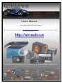
(044)361-05-06
ICQ:495-089-192
(067)469-02-12
ICQ:613-211-859
(099)048-99-03
(093)672-77-76
User's Manual
Car amplifier Alpine PDX-F4 4-channel
In the online store Winauto you also can buy auto amplifier Alpine PDX-F4 . Delivery in Kiev and throughout Ukraine
with payment upon receipt!
http://winauto.ua
Car Receivers - Facia Plates - Head Units - TV and Monitors - Car Antennas - Car Audio - Car DVRs - GPS Navigation - Trip Computers - Security
Systems - Mechanical Locking - Car Park Systems - Cameras - Optic and Light - Car Tuning - Car Heating - Marine Audio and Electronics - Car
Accessories - Car Isolation - Car Installation Components - Car Batteries - Liquid and Oil -
Car audio and car goods internet store Winauto
FOR CAR USE ONLY/POUR APPLICATION AUTOMOBILE UNIQUEMENT/PARA USO EN AUTOMÓVILES
Introduction:
Please read this OWNER'S MANUAL thoroughly
ALPINE hope that your new PDX-F6/F4 will give
In case of problems when installing your PDX-F6
CAUTION: These controls are for tuning your
adjustment.
PDX-F6
PDX-F4
ALPINE ELECTRONICS OF AMERICA, INC.
19145 Gramercy Place, Torrance,
California 90501, U.S.A.
Phone 1-800-ALPINE-1 (1-800-257-4631)
ALPINE ELECTRONICS OF CANADA, INC.
777 Supertest Road, Toronto,
Ontario M3J 2M9, Canada
Phone 1-800-ALPINE-1 (1-800-257-4631)
Qingdao Dongli Xinhaiyuan
Printing Co., Ltd.
No.17, jiushuidong road,
Qingdao, China
ALPINE ELECTRONICS OF AUSTRALIA PTY. LTD.
161-165 Princes Highway, Hallam
Victoria 3803, Australia
Phone 03-8787-1200
ALPINE ITALIA S.p.A.
Viale C. Colombo 8, 20090
Trezzano Sul Naviglio (MI), Italy
Phone 02-484781
ALPINE ELECTRONICS GmbH
Wilhelm-Wagenfeld-Str. 1-3,
80807 München, Germany
Phone 089-32 42 640
ALPINE ELECTRONICS DE ESPAÑA, S.A.
Portal de Gamarra 36,
Pabellón, 32
01013 Vitoria (Alava) - APDO
133, Spain
Phone 945-283588
w
ALPINE ELECTRONICS MARKETING, INC.
1-1-8 Nishi Gotanda,
Shinagawa-ku,
Tokyo 141-0031, Japan
Phone 03-5496-8231
in
au
to
.u
• OWNER'S MANUAL
Please read this manual to maximize your enjoyment
of the outstanding performance and feature capabilities
of the equipment, then retain the manual for future
reference.
• MODE D'EMPLOI
Veuillez lire ce mode d'emploi pour tirer pleinement
profit des excellentes performances et fonctions de cet
appareil, et conservez-le pour toute référence future.
• MANUAL DE OPERACION
Lea este manual, por favor, para disfrutar al máximo
de las excepcionales prestaciones y posibilidades
funcionales que ofrece el equipo, luego guarde el manual
para usarlo como referencia en el futuro.
a
4 CHANNEL POWER AMPLIFIER
ALPINE ELECTRONICS OF U.K. LTD.
Alpine House
Fletchamstead Highway,
Coventry CV4 9TW, U.K.
Phone 0870-33 33 763
ALPINE ELECTRONICS FRANCE S.A.R.L.
(RCS PONTOISE B 338 101 280)
98, Rue de la Belle Etoile,
Z.I. Paris Nord II, B.P. 50016,
95945 Roissy Charles de Gaulle
Cedex, France
Phone 01-48638989
ALPINE ELECTRONICS (BENELUX) GmbH
Leuvensesteenweg 510-B6,
1930 Zaventem, Belgium
Phone 02-725-13 15
WARNING
This symbol means importa
Failure to heed them can res
CAUTION
This symbol means importa
Failure to heed them can res
• DO NOT OPERATE ANY FUNCTION THAT TA
YOUR VEHICLE. Any function that requires your
complete stop. Always stop the vehicle in a safe loc
an accident.
• KEEP THE VOLUME AT A LEVEL WHERE YO
Excessive volume levels that obscure sounds such a
etc.) can be dangerous and may result in an acciden
CAUSE HEARING DAMAGE.
• DO NOT DISASSEMBLE OR ALTER. Doing s
• USE THIS PRODUCT FOR MOBILE 12V APP
result in fire, electric shock or other injury.
• USE THE CORRECT AMPERE RATING WHE
electric shock.
• DO NOT BLOCK VENTS OR RADIATOR PAN
in fire.
• MAKE THE CORRECT CONNECTIONS. Failu
damage.
• USE ONLY IN CARS WITH A 12 VOLT NEGAT
Failure to do so may result in fire, etc.
• BEFORE WIRING, DISCONNECT THE CABLE
so may result in electric shock or injury due to e
• DO NOT ALLOW CABLES TO BECOME ENTA
cables in compliance with the manual to preven
hang up on places such as the steering wheel,
• DO NOT SPLICE INTO ELECTRICAL CABLE
equipment. Doing so will exceed the current ca
• DO NOT DAMAGE PIPE OR WIRING WHEN D
installation, take precautions so as not to conta
wiring. Failure to take such precautions may re
• DO NOT USE BOLTS OR NUTS IN THE BRAK
CONNECTIONS. Bolts or nuts used for the bra
tanks should NEVER be used for installations o
the vehicle and cause fire etc.
• KEEP SMALL OBJECTS SUCH AS BOLTS O
them may result in serious injury. If swallowed,
68-13530Z50-A
M3514414010
Printed in China (Y)
• HALT USE IMMEDIATELY IF A PROBLEM AP
to the product. Return it to your authorized Alpi
• HAVE THE WIRING AND INSTALLATION DON
special technical skill and experience. To ensur
product to have the work done.
• USE SPECIFIED ACCESSORY PARTS AND I
accessory parts. Use of other than designated
the unit in place. This may cause parts to becom
• ARRANGE THE WIRING SO IT IS NOT CRIMP
cables and wiring away from moving parts (like
crimping and damage to the wiring. If wiring pa
the wire’s insulation from being cut by the meta
• DO NOT INSTALL IN LOCATIONS WITH HIGH
with high incidence of moisture or dust. Moistur
failure.
SERVICE CARE
A Top Cover/
Couvercle
supérieur/
Tapa superior
◆ IMPORTANT NOTICE
This Amplifier has been type tested and found to
comply with the limits for a Class B computing de
accordance with the specifications in Subpart J o
15 of FCC Rules. This equipment generates and
radio frequency energy, and it must be installed a
used properly in accordance with the manufactur
instructions.
◆ For European Customers
Should you have any questions about warranty, p
Car audio and car goods internet store Winauto
CONNECTIONS (Fig. 5 - Fig. 8)
Before making connections, be sure to turn the power o
audio components. Connect the yellow battery lead from
amp directly to the positive (+) terminal of the vehicle's
Do not connect this lead to the fuse block.
30
30
CAUTION
◆ Caution on connection terminals/part
•
Keep electrically conductive objects away from the u
terminals/parts (power terminals, fuses, speaker ou
terminals, RCA connectors, etc.). Doing so prevents
possible short circuit and damage to the unit.
To prevent external noise from entering the audio sy
• Locate the unit and route the leads at least 10 cm (3
15/16") away from the car harness.
• Keep the battery power leads as far away from othe
as possible.
• Connect the ground lead securely to a bare metal sp
(remove any paint or grease if necessary) of the car
chassis.
• If you add an optional noise suppressor, connect it a
far away from the unit as possible. Your Alpine deale
carries various noise suppressors, contact them for
information.
• Your Alpine dealer knows best about noise preventio
measures so consult your dealer for further informat
Fig. 5
b Fuse (30A x 2)
• USE ONLY THE CORRECT AMPERE RATING WH
REPLACING FUSES.
Failure to do so may result in fire or electric shock.
a
Wire/Conducteur/Conductor 7-10 mm (9/32" -3/8")
to
.u
Wire Terminal/Borne de conducteur/
Terminal del conductor
Fig. 6
A Battery Connector/Connecteur de la
batterie/Conector de batería
B Hexagon screw (Large)/Vis à six pans
(grande)/Tornillo hexagonal (grande)
C Hexagon screw (Small)/Vis à six pans
(petite)/Tornillo hexagonal (pequeña)
D Ground lead/Conducteur de mise à la
terre/Cable de tierra
E Remote turn-on lead/Conducteur de
mise sous tension télécommandée/
Cable para encendido remoto
F Battery lead/Conducteur de la batterie/
Cable de la batería
in
au
w
a Power Supply Terminal
Fig. 7
A Speaker connector/Connecteur du hautparleur/Conector de altavoz
B Hex screw hole/Orifice de la vis à six
pans/Agujero de tornillo hexagonal
C Negative lead terminal hole/Orifice de la
borne du conducteur négatif/Agujero del
terminal del conductor negativo
D Speaker wire (negative)/Câble du
haut-parleur (négatif)/Cable del altavoz
(negativo)
E Positive lead terminal hole/Orifice de la
borne du conducteur positif/Agujero del
terminal del conductor positivo
F Speaker wire (positive)/Câble du
haut-parleur (positif)/Cable del altavoz
(positivo)
Fig. 8
c Speaker Output Terminals
Referring to “Cautions on speaker wire connections”, in
the speaker wire into the speaker connector, which is th
inserted in the speaker output terminal.
Notes:
• Fully insert the speaker connector to avoid poor connect
the wire coming loose due to vehicle vibration, etc.
• The speaker connector can be connected either way, rega
of polarity indication.
• Do not connect speaker leads together or to chassis grou
d RCA Input Jacks
Connect these jacks to the line out leads on your head
using RCA extension cables (sold separately).
e Battery Connector
Make the Battery, Remote Turn-on and Ground lead
connections (as shown) to the Battery Connector. Inser
to Terminal 1.
f Battery Lead (Yellow, sold separately)
Be sure to add a a fuse as close as possible to the batte
positive (+) terminal. This fuse will protect your vehicle's
electrical system in case of a short circuit. If you need to
extend this lead, only use 4AWG-6AWG/13 mm2 - 21 m
wire gauge) for this connection.
g Remote Turn-On Lead (Blue/White, sold separate
Connect this lead to the remote turn-on or power antenn
(positive trigger, (+) 12V only) lead of your head unit.
h Ground Lead (Black, sold separately)
Connect this lead securely to a clean, bare metal spot o
the vehicle's chassis. Verify this point to be a true groun
checking for continuity between that point and the nega
(–) terminal of the vehicle's battery. Ground all your aud
components to the same point on the chassis to preven
ground loops.
SWITCH SETTINGS (Fig. 9)
When making adjustments 10-15 below, remove the he
screw (indicated by ★ in the illustration) using the hexag
wrench (small, supplied), and then open the control cov
i Power Indicator
Lights up when power is on.
Is off when power is off.
j, m Input Gain Adjustment Control
Set the PDX-F6/F4 input gain to the minimum (4V) posi
Using a dynamic CD as a source, increase the head un
volume until the output distorts. Then, reduce the volum
step (or until the output is no longer distorted). Now, inc
the amplifier gain until the sound from the speakers bec
distorted. Reduce the gain slightly so the sound is no lo
distorted to achieve the optimum gain setting.
p Status Indicator
Indication color
Blue
Status
Amplifier circuit is normal.
Amplifier circuit is abnormal. An
electrical short has occurred, or
supply current is too high.
Red
Ambient temperature is too high.