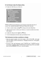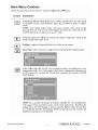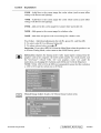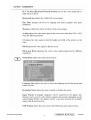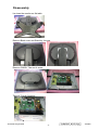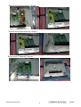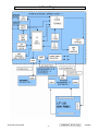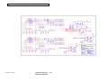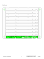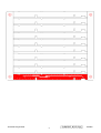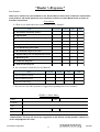
1
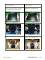
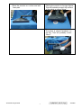
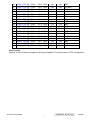
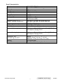
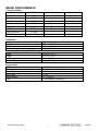
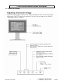
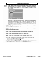
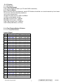
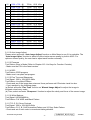
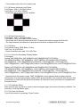
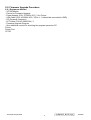
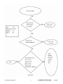
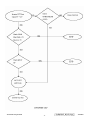
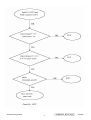
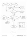
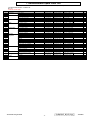
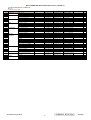
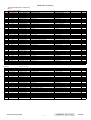
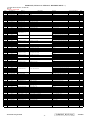
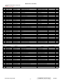
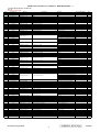
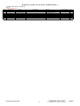
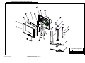
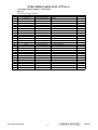
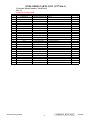
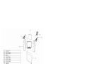
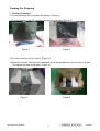
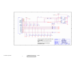
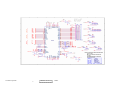
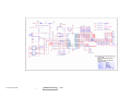
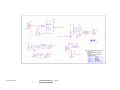
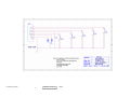
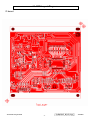
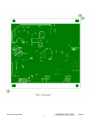
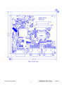
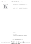
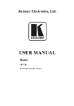
Service Manual ViewSonic VP730/b Model No. VS10726 17” Color TFT LCD Display (VP730/b_SM Rev. 1a Oct. 2005) ViewSonic 381 Brea Canyon Road, Walnut, California 91789 USA - (800) 888-8583 Copyright Copyright ¤ 2005 by ViewSonic Corporation. All rights reserved. No part of this publication may be reproduced, transmitted, transcribed, stored in a retrieval system, or translated into any language or computer language, in any form or by any means, electronic, mechanical, magnetic, optical, chemical, manual or otherwise, without the prior written permission of ViewSonic Corporation. Disclaimer ViewSonic makes no representations or warranties, either expressed or implied, with respect to the contents hereof and specifically disclaims any warranty of merchantability or fitness for any particular purpose. Further, ViewSonic reserves the right to revise this publication and to make changes from time to time in the contents hereof without obligation of ViewSonic to notify any person of such revision or changes. Trademarks Optiquest is a registered trademark of ViewSonic Corporation. ViewSonic is a registered trademark of ViewSonic Corporation. All other trademarks used within this document are the property of their respective owners. Revision History Revision SM Editing Date 1a 10/17/05 Description of Changes ECR Number Editor G. Han Initial Release Confidential - Do Not Copy ViewSonic Corporation i VP730/b TABLE OF CONTENTS 1. Precautions and Safety Notices 1 2. Specification 5 3. Front Panel Function Control Description 10 4. Circuit Description 17 5. Adjustment Procedure 18 6. Troubleshooting Flow Chart 30 7. Recommended Spare Parts List 35 8. Exploded Diagram and Exploded Parts List 43 9. Block Diagram 50 10. Schematic Diagrams 51 11. PCB Layout Diagrams 57 Confidential - Do Not Copy ViewSonic Corporation ii VP730/b 1. Precautions and Safety Notices 1. Appropriate Operation (1) (2) (3) (4) (5) (6) (7) (8) (9) (10) Turn off the product before cleaning. Use only a dry soft cloth when cleaning the LCD panel surface. Use a soft cloth soaked with mild detergent to clean the display housing. Use only a high quality, safety approved AC/DC power cord. Disconnect the power plug from the AC outlet if the product will not be used for a long period of time. If smoke, abnormal noise, or strange odor is present, immediately switch the LCD display off. Do not touch the LCD panel surface with sharp or hard objects. Do not place heavy objects on the LCD display, video cable, or power cord. Do not use abrasive cleaners, waxes or solvents for your cleaning. Do not operate the product under the following conditions: - Extremely hot, cold or humid environment. - Areas containing excessive dust and dirt. - Near any appliance generating a strong magnetic field. - In direct sunlight. 2. Caution No modification of any circuit should be attempted. Service work should only be performed after you are thoroughly familiar with all of the following safety checks and servicing guidelines. 3. Safety Check Care should be taken while servicing this LCD display. Because of the high voltage used in the inverter circuit, the voltage is exposed in such areas as the associated transformer circuits. 4. LCD Module Handling Precautions 4.1 Handling Precautions (1) Since front polarizer is easily damaged, pay attention not to scratch it. (2) Be sure to turn off power supply when connecting or disconnecting input connector. (3) Wipe off water drops immediately. Long contact with water may cause discoloration or spots. (4) When the panel surface is soiled, wipe it with absorbent cotton or other soft cloth. (5) Since the panel is made of glass, it may break or crack if dropped or bumped on hard surface. (6) Since CMOS LSI is used in this module, take care of static electricity and ensure human earth when handling. (7) Do not open or modify the Module Assembly. (8) Do not press the reflector sheet at the back of the module in any direction. (9) In the event that a Module must be put back into the packing container slot after it was taken out of the container, do not press the center of the CCFL Reflector edge. Instead, press at the far ends of the CFL Reflector edge softly. Otherwise the TFT Module may be damaged. (10) At the insertion or removal of the Signal Interface Connector, be sure not to rotate or tilt the Interface Connector of the TFT Module. Confidential Do Not Copy ViewSonic Corporation 1 VP730/b (11) After installation of the TFT Module into an enclosure (LCD monitor housing, for example), do not twist or bend the TFT Module even momentarily. When designing the enclosure, it should be taken into consideration that no bending/twisting forces may be applied to the TFT Module from outside. Otherwise the TFT Module may be damaged. (12) The cold cathode fluorescent lamp in the LCD contains a small amount of mercury. Please follow local ordinances or regulations for disposal. (13) The LCD module contains a small amount of materials having no flammability grade. The LCD module should be supplied with power that complies with the requirements of Limited Power Source (IEC60950 or UL1950), or an exemption should be applied for. (14) The LCD module is designed so that the CCFL in it is supplied by a Limited Current Circuit (IEC60950 or UL1950). Do not connect the CCFL to a Hazardous Voltage Circuit. Confidential Do Not Copy ViewSonic Corporation 2 VP730/b Incorrect Methods: Correct Methods: Only touch the metal frame of the LCD panel or the front cover of the monitor.Do not touch the surface of the polarizer. Take out the monitor with cushions Surface of the LCD panel is pressed by fingers and that will probably cause “Mura”. Taking out the monitor by grasping the LCD panel.That will probably cause “Mura”. Confidential Do Not Copy ViewSonic Corporation 3 VP730/b Place the monitor on a clean and soft foam pad. Placing the monitor on foreign objects. That will probably scratch the surface of the panel or cause “Mura.” The panel is placed facedown on the lap. That will probably cause “Mura.” Confidential Do Not Copy ViewSonic Corporation 4 VP730/b 2.SPECIFICATIONS GENERAL specification Test Resolution & Frequency Test Image Size Contrast and Brightness Controls 1280x1024 @ 60Hz Full Size Factory Default: Contrast = 70%, Brightness = 100% VIDEO INTERFACE Input Connector D-SUB1= DB-15(Analog) D-SUB2= DB-15(Analog) DVI= DVI-D(Digital) Default Input Connector Defaults to the first detected input Equal to twice the weight of the monitor for Video Cable Strain Relief five minutes Video Cable Connector DB-15 Pin Compliant DDC 2B out Video RGB (Analog) Video Signals Separate Sync / Composite Sync / SOG TMDS (Digital) Video Impedance 75 Ohms (Analog), 100 Ohms (Digital) Maximum PC Video Signal 950 mV with no damage to monitor Maximum Mac Video Signal 1250 mV with no damage to monitor Sync Signals TTL DDC/CI Compliant with Revision 1.0 Separate Sync / Composite Sync / SOG Sync Compatibility Video Compatibility Resolution Compatibility Exclusions Shall be compatible with all PC type computers, Macintosh computers, and after market video cards 640 x 350, 640 x 400, 640 x 480, 640 x 870, 720 x 400, 720 x 480, 720 x 576, 800 x 600, 832 x 624, 1024 x 768, 1152 x 864, 1152 x 870, 1280 x 720, 1280 x 768, 1280 x 960, 1280 x 1024 Not compatible with interlaced video Horizontal / Vertical Frequency Horizontal Frequency 24 – 82 kHz Vertical Refresh Rate 50 – 85 Hz Maximum Pixel Clock Sync Polarity 135 MHz Independent of sync polarity Confidential Do Not Copy ViewSonic Corporation 5 VP730/b Table : 15 pin D-sub connector pin assignment Pin Number 1 2 3 4 5 6 7 8 9 10 11 12 13 14 15 Pin Function Red video input Green video input Blue video input No Connection Ground Red video ground Green video ground Blue video ground +5V Ground No connection (SDA) Horizontal sync (Composite sync) Vertical sync (SCL) Timing Table Item 1 2 3 4 5 6 7 8 9 10 11 12 13 14 15 16 17 18 19 20 21 22 23 24 25 640 x 350 640 x 400 640 x 400 640 x 480 640 x 480 640 x 480 640 x 480 640 x 480 640 x 480 640 x 870 720 x 400 720 x 400 720 x 480 720 x 576 800 x 600 800 x 600 800 x 600 800 x 600 800 x 600 800 x 600 832 x 624 1024 x 768 1024 x 768 1024 x 768 1024 x 768 Timing @ 70 Hz, @ 60 Hz, @ 70 Hz, @ 50 Hz, @ 60 Hz, @ 67 Hz, @ 72 Hz, @ 75 Hz, @ 85 Hz, @ 75 Hz, @ 70 Hz, @ 85 Hz, @ 60 Hz, @ 50 Hz, @ 50 Hz, @ 56 Hz, @ 60 Hz, @ 72 Hz, @ 75 Hz, @ 85 Hz, @ 75 Hz, @ 50 Hz, @ 60 Hz, @ 70 Hz, @ 72 Hz, 31.5 31.5 31.5 24.7 31.5 35.0 37.9 37.5 43.3 68.9 31.5 37.9 31.5 31.3 24.7 35.1 37.9 48.1 46.9 53.7 49.7 39.6 48.4 56.5 58.1 KHz KHz KHz KHz KHz KHz KHz KHz KHz KHz KHz KHz KHz KHz KHz KHz KHz KHz KHz KHz KHz KHz KHz KHz KHz Analog Yes Yes Yes Yes Yes Yes Yes Yes Yes Yes Yes Yes Yes Yes Yes Yes Yes Yes Yes Yes Yes Yes Yes Yes Yes Digital Yes Yes Yes Yes Yes Yes Yes Yes Yes Yes Yes Yes Yes Yes Yes Yes Yes Yes Yes Yes Yes Yes Yes Yes Yes Remark DMT DMT DMT DMT DMT For MAC DMT DMT DMT MAC DMT DMT 480p 576p DMT DMT DMT DMT DMT DMT MAC DMT DMT DMT DMT Confidential Do Not Copy ViewSonic Corporation 6 VP730/b 26 1024 x 768 27 1024 x 768 28 1024 x 768 29 1152 x 864 30 1152 x 870 31 1280 x 720 32 1280 x 720 33 1280 x 768 34 1280 x 768 35 1280 x 768 36 1280 x 768 37 1280 x 768 38 1280 x 960 39 1280 x 960 40 1280 x 960 41 1280 x 1024 42 1280 x 1024 43 1280 x 1024 @ @ @ @ @ @ @ @ @ @ @ @ @ @ @ @ @ @ 75 Hz, 75 Hz, 85 Hz, 75 Hz, 75 Hz, 50 Hz, 60 Hz, 50 Hz, 60 Hz, 60 Hz, 75 Hz, 85 Hz, 50 Hz, 60 Hz, 75 Hz, 50 Hz, 60 Hz, 75 Hz, 60.0 60.2 68.7 67.5 68.7 37.5 45.0 39.6 47.4 47.8 60.3 68.6 49.4 59.7 75.2 52.7 64.0 80.0 KHz KHz KHz KHz KHz KHz KHz KHz KHz KHz KHz KHz KHz KHz KHz KHz KHz KHz Yes Yes Yes Yes Yes Yes Yes Yes Yes Yes Yes Yes Yes Yes Yes Yes Yes Yes Yes Yes Yes Yes Yes Yes Yes Yes Yes Yes Yes Yes Yes Yes Yes Yes Yes Yes DMT For MAC DMT DMT For MAC 720p 720p DMT DMT DMT DMT DMT DMT DMT DMT DMT DMT DMT User Presets Number of User Presets (recognized timings) Available: 10 presets total in FIFO configuration Confidential Do Not Copy ViewSonic Corporation 7 VP730/b Panel Characteristics Model number Type Active Size Pixel Arrangement Pixel Pitch Glass Treatment # of Backlights Backlight Life Luminance (Center)– CT = 6500K, Contrast / Brightness = Brightness Uniformity Contrast Ratio Color Depth Horizontal Viewing Angle Vertical Viewing Angle Response Time 10%-90% @ Ta=25°C Mercury Panel Defects AUO M170eG01 V.8 Active Matrix TFT, 0 technology 17” RGB Vertical Stripe 0.264 mm Anti Glare 4 CCFL 50,000 Hours (Typ) 30,000 Hours (Min) 300 cd/m2 (Typ after 30 minute warm up) 240 cd/m2 (Min after 30 minute warm up) 80%(Typ) / 75%(Min) 500:1 (Typ), 300:1 (Min) 16.7 million colors (8 bit panel) 140 degress (Typ) / 120 degrees (Min) @ CR>10 160 degress (Typ) @ CR>5 130degress (Typ) / 110 degrees (Min) @ CR>10 160 degress (Typ) @ CR>5 On/Off Typical= 8 ms (Tr= 6 ms, Tf = 2 ms) Maximun =13 ms (Tr= 9 ms, Tf = 4 ms) 3.0 mg per lamp Please see Panel Quality Specifications. Confidential Do Not Copy ViewSonic Corporation 8 VP730/b IMAGE PERFORMANCE Factory Defaults Item Contrast Brightness Color Temperature Sharpness OSD H. Position OSD V. Position OSD Time Out OSD Background Defaults 70% 100% 6500K 100% 50% 50% 15 Sec Enabled Dimension Width Height Depth Monitor Weight Dimension (Head Only / Wall Mount) Width Height Depth Monitor Weight Ergonomics Tilt Up Tilt Down Swivel Right Swivel Left Height Adjust Pivot Item 720x400/640x400 Resolution Notice Volume Balance Treble Bass Defaults 720x400 Enabled N/A N/A N/A N/A 372 mm (14.6 “) 477 mm (18.8”) 279 mm (11”) 5.7 kg (12.6 lbs) 308 mm (12.1”) 372 mm (14.6”) 56 mm (2.2”) 3.4 kg (7.5 lbs) ≧20º From 0º down to -3º ~ -5 º ≧135º ≧135º 0 ≧ 135 mm 0~90 degress (clockwise) Confidential Do Not Copy ViewSonic Corporation 9 VP730/b 3. Front Panel Function Control Description 3.1 Location of Controls Confidential Do Not Copy ViewSonic Corporation 10 VP730/b Confidential Do Not Copy ViewSonic Corporation 11 VP730/b Confidential Do Not Copy ViewSonic Corporation 12 VP730/b Confidential Do Not Copy ViewSonic Corporation 13 VP730/b Confidential Do Not Copy ViewSonic Corporation 14 VP730/b Confidential Do Not Copy ViewSonic Corporation 15 VP730/b Hot Key for Function Controls Buttons: [1] [2] [Up] or [Dn] [Up] + [Dn] [1] + [2] Functions: Main menu Input Select To immediately activate Contrast menu. It should be change to Brightness OSD by push button [2] Recall both of Contrast and Brightness to default Toggle 720x400 and 640x400 mode when input 720x400 or 640x400 mode. Auto White Balance.(Not shown on user’s guide) Power Lock OSD Lock Didable Theft Defence function All reset [1] + [Up] + [Dn] [1] + [Dn] [1] + [Up] [1] + [Dn] + [2] [Up] + [PW] + Main Power On No signal + [PW] +[2] + Burning mode Main Power on Signal + [PW] +[2] + Main Factory Mode Power on Remark : All the short cuts function are only available while OSD off Confidential Do Not Copy ViewSonic Corporation 16 VP730/b 4. Circuit Description 1. WORKING THEOREM A. Scaler The TSU66AJ is total solution graphics processing IC for LCD monitors with panel resolutions up to SXGA. It is configured with a high-speed integrated triple-ADC/PLL, an integrated DVI receiver, a high quality display processing engine, and an integrated output display interface that can support LVDS panel interface format. To further reduce system costs, the TSU66AJ also integrates intelligent power management control capability for green-mode requirements and spread-spectrum support for EMI management. The TSU66AJ incorporates the world’s first coherent oversampled RGB graphics ADC in a monitor controller system1. The oversampling ADC samples the input RGB signals at a frequency that is much higher than the signal source pixel rate. This can preserve details in the video signal that ordinarily would be lost due to input signal jitter or bandwidth limitations in non-oversampled systems. The TSU66AJ also incorporates a new Dynamic Frame Rate (DFR) generator2 for the digital output video to the display panel that preserves the advantages of a fixed output clock rate, while eliminating the output end of frame short-line. ? B. MCU: The MTV416M micro-controller is an 8051 CPU core embedded device targeted for LCD Monitor or LCD TV application. It includes an 8051 CPU core, a 128K-byte internal program Flash-ROM, a 768-byte SRAM, 4 channels of PWM DAC, 4 channels of 6-bit ADC, and a built-in sync-processor. It also includes two IIC Slave B ports, supporting VESA DDC/CI for both D-sub and DVI interfaces, and a Boot-Code-Free ISP (In System Programming). Confidential Do Not Copy ViewSonic Corporation 17 VP730/b 5. Adjusting Procedure Confidential Do Not Copy ViewSonic Corporation 18 VP730/b 5-1.1 Product 17” LCD Monitor 5-1.2 Test Equipment Color Video Signal & Pattern (or PC with SXGA resolution) 5-1.3 Test Condition Before function test and alignment, each LCD Monitor should be run-in and warmed up for at least 30 minutes with the following conditions: (a) In room temperature, (b) With full-white screen, RGB, and Black (c) With cycled display modes, 640*480 (H=43.27 kHz, V=85Hz) 800*600 (H=53.7 kHz, V=85Hz) 1024*768 (H=68.67 kHz, V=85Hz) 1280*1024(H=80.0KHz, V=75Hz) 5-1.4 Test Display Modes & Pattern 5-1.4.1 Compatible Modes Analog Digital Item 1 640 x 350 2 640 x 400 3 640 x 400 4 640 x 480 5 640 x 480 6 640 x 480 7 640 x 480 8 640 x 480 9 640 x 480 10 640 x 870 11 720 x 400 12 720 x 400 13 720 x 480 14 720 x 576 15 800 x 600 16 800 x 600 17 800 x 600 18 800 x 600 19 800 x 600 20 800 x 600 21 832 x 624 22 1024 x 768 23 1024 x 768 24 1024 x 768 25 1024 x 768 Timing @ 70 Hz, @ 60 Hz, @ 70 Hz, @ 50 Hz, @ 60 Hz, @ 67 Hz, @ 72 Hz, @ 75 Hz, @ 85 Hz, @ 75 Hz, @ 70 Hz, @ 85 Hz, @ 60 Hz, @ 50 Hz, @ 50 Hz, @ 56 Hz, @ 60 Hz, @ 72 Hz, @ 75 Hz, @ 85 Hz, @ 75 Hz, @ 50 Hz, @ 60 Hz, @ 70 Hz, @ 72 Hz, 31.5 31.5 31.5 24.7 31.5 35.0 37.9 37.5 43.3 68.9 31.5 37.9 31.5 31.3 24.7 35.1 37.9 48.1 46.9 53.7 49.7 39.6 48.4 56.5 58.1 KHz KHz KHz KHz KHz KHz KHz KHz KHz KHz KHz KHz KHz KHz KHz KHz KHz KHz KHz KHz KHz KHz KHz KHz KHz Confidential Do Not Copy ViewSonic Corporation 19 VP730/b 26 27 28 29 30 31 32 33 34 35 36 37 38 39 40 41 42 43 1024 x 768 1024 x 768 1024 x 768 1152 x 864 1152 x 870 1280 x 720 1280 x 720 1280 x 768 1280 x 768 1280 x 768 1280 x 768 1280 x 768 1280 x 960 1280 x 960 1280 x 960 1280 x 1024 1280 x 1024 1280 x 1024 @ @ @ @ @ @ @ @ @ @ @ @ @ @ @ @ @ @ 75 Hz, 75 Hz, 85 Hz, 75 Hz, 75 Hz, 50 Hz, 60 Hz, 50 Hz, 60 Hz, 60 Hz, 75 Hz, 85 Hz, 50 Hz, 60 Hz, 75 Hz, 50 Hz, 60 Hz, 75 Hz, 60.0 60.2 68.7 67.5 68.7 37.5 45.0 39.6 47.4 47.8 60.3 68.6 49.4 59.7 75.2 52.7 64.0 80.0 KHz KHz KHz KHz KHz KHz KHz KHz KHz KHz KHz KHz KHz KHz KHz KHz KHz KHz 5-1.5.2 Auto Image Adjust Please select and enter “Auto Image Adjust” function on Main Menu to see if it is workable. The “Auto Image Adjust” function is aimed to offer a better screen quality by built-in ASIC. For optimum screen quality, the user has to adjust each function manually. 5-1.5.3 Firmware Test Pattern: Burn in Mode (Refer to Chapter III-3. Hot Keys for Function Controls) - Make sure the F/W is the latest version. 5-1.5.4 DDC Test Pattern: EDID program - Make sure it can pass test program. 5-1.5.5 Fine Tune and Sharpness Test Signal: 1280 x 1024 @ 60.0kHz Test Pattern: Line Moiré Pattern - Check and see if the image has noise and focus performs well. Eliminate visual line bar. - If not, readjust by the following steps: (a) Select and enter “Fine Tune” function on “Manual Image Adjust” to adjust the image to eliminate visual wavy noise. (b) Then, select and enter “Sharpness” function to adjust the clarity and focus of the screen image. 5-1.5.6 White Balance Test Signal: 640*480@60Hz Test Pattern: Full White and Black Pattern 5-1.5.7 R, G, B, Colors Contrast Test Signal: 1280 x 1024 @ 60.0kHz Test Pattern: R, G, B, Color Intensities Pattern and 16 Gray Scale Pattern - Check and see if each color is normal and distinguishable. Confidential Do Not Copy ViewSonic Corporation 20 VP730/b - If not, please return the unit to repair area. 5-1.5.8 Screen Uniformity and Flicker Test Signal: 1280 x 1024 @ 60.0kHz Test Pattern: Full White Pattern - Check and see if it is in normal condition. 5-1.5.9 Dead Pixel and Line Test Signal: 1280 x 1024 @ 60.0kHz Test Pattern: Dark and White Screen Pattern - Check and see if there are dead pixels on LCD panel with shadow gauge and filter film. - The total numbers and distance of dead pixels should be compliant with the spec. 5-1.5.10 Mura Test Pattern: White, RGB, Black, & Grey Test Tool: 10 % ND Filter - Check if the Mura can pass 10 % ND Filter. 5-1.5.11 Check for Secondary Display Modes Test Signal: Analog: 640*350@70Hz; 640*400@60Hz;640*480@50/60/67/72/75/85Hz; 720*400@70Hz/85Hz; 720*480@60Hz; 720*576@50Hz; 800*600@56/60/72/75/85Hz; 832*624@75Hz, 1024*768@50/60/70/72/75/85Hz; 1152*864@75Hz; 1152*870@75Hz; 1280*720@50/60Hz; 1280*768@50/60/75/85Hz; 1280*960@50/60/75Hz; 1280*1024@50/60/75Hz Digital: 640*350@70Hz; 640*400@60Hz;640*480@50/60/67/72/75/85Hz; 720*400@70Hz/85Hz; 720*480@60Hz; 720*576@50Hz; 800*600@56/60/72/75/85Hz; 832*624@75Hz, 1024*768@50/60/70/72/75/85Hz; 1152*864@75Hz; 1152*870@75Hz; 1280*720@50/60Hz; 1280*768@50/60/75/85Hz; 1280*960@50/60/75Hz; 1280*1024@50/60/75Hz - Normally when the primary mode 1280*1024@60Hz is well adjusted and compliant with the specification, the secondary display modes will be great possible to be compliant with the spec. But we still have to check with the general test pattern to make sure every secondary is compliant with the specification. 5-1.5.12 All Modes Reset After final QC step, we have to erase all saved changes again and restore the factory defaults. You should do “All Mode Reset” again. 5-1.5.13 Power off Monitor Turn off the monitor by pressing “Power” button. Confidential Do Not Copy ViewSonic Corporation 21 VP730/b 5-2. Firmware Upgrade Procedure 5-2.1 Equipment Needed - VP730 Monitor - Fixture for Firmware Upgrade - Power Adapter (P/N: 47.58201.001) *1 for Fixture - VGA Cable (P/N: 42.59901.003) *1(Pin 4, 11 should be connected to GND) - PC (Personal Computer) - LPT Cable (P/N: 42.59906.001) *1 - Firmware Upgrade Program - One additional monitor for checking the program execution PC Fixture Printer Port VP730 Confidential Do Not Copy ViewSonic Corporation 22 VP730/b 5.3 . EDID Procedure DDC User’s manual 1. Hardware installation A. The EDID cable has equipped 2 different terminals; one is male 25 pin printer connector and another side is male 15 pin D-sub connecter. B. Connect the EDID cable from PC Printer port to monitor D-sub connector. C. Make sure the monitor was working under power saving mode and keep it at “Power Saving state” during DDC process. EDID-Kit Cable PC printer port 25pin connector D-Sub of Monitor 15pin VGA Confidential Do Not Copy ViewSonic Corporation 23 VP730/b 2. Programming procedure A. Normally, you received a EDID zip file of new model. You need to unzipped it. B. There will need the following files for DDC program: (VP730 is an example) 1. DPS.EXE 2. VP730.BAT 3. VP730.DDC 4. VP730.CFG 5. VP730.DPS C. Execute the VP730.BAT (for VP730 monitor only) from Programming PC. Below screen will display. Fig-DDC1 Refer to Fig-DDC1; you have to select the required item if the display data was not you want. Press 1: For year, the cursor will move to the column behind “Edit Year” than you can key in the data you want after that press enter to exit and return. (It needs 4 numbers for this data) Press 2: For week, the cursor will move to the column behind “Edit Week” than you can key in the data you want after that press enter to exit and return. (This data is within 1 ~ 53.) Press 3: For S/N,, the cursor will move to the column behind “Edit S/N” than you can key in the data you want after that press enter to exit and return. (This data is within 0 ~ 99999, 5 numbers max.) Confidential Do Not Copy ViewSonic Corporation 24 VP730/b D. Press “ESC” or “Enter” key to return main menu, the Fig-DDC2 will be displayed and the correct serial number will show on right corner of screen. Fig-DDC2 Display updated serial number. Under Fig-DDC2, you could change the “Week” data by press “*” key and the “S/N” data by press ““ key. Press 3 “DDC Writer/Check Data”: The Kit will start to program new data of EDID into monitor, all DDC data will display on the screen after programming. Please refer to Fig-DDC3 below, the DDC process is finished. Fig-DDC3 Confidential Do Not Copy ViewSonic Corporation 25 VP730/b The message (E2PROM Acknowledge Not Echo) will display on the screen if there is any error detected by Programming PC. If error message is happened, please re-check the connection of cable and return to first step. Please refer to the Viewsonic EDID data format that was printing on ID label. PPPYYWWxxxxx PPP = Viewsonic Regional Product ID Code, EX. VE500 is “910”, VE700 is “A10” and VG900 is “A1C ”. YY= 2 digits of Manufacturing year. (range 1996-2015). WW = 2 digits of Manufacturing week (range 01-54). xxxxx = 5 digits of Sequence number. (range 00001-99999). Confidential Do Not Copy ViewSonic Corporation 26 VP730/b 5.4 . ISP procedure Connection of ISP Kit: Using ISP cable connect PC Print port Using VGA cable connect monitor (destination). Confidential Do Not Copy ViewSonic Corporation 27 VP730/b Setting of ISP program on PC 1. 2. 3. 4. Setup MYSON ISP program, Execute ISP program to get the window below Select “MTV416M128” MCU type, Select CPU=5 MHz MTV Type CPU=5 Type 5. Click “Load MCU file” and then find the updated firmware code. 6. Click “Create Security File” going to next window MCU File Type Create Security File 7. Select Command No=4 Confidential Do Not Copy ViewSonic Corporation 28 VP730/b 8. Put ISP Slave Add=94 ; Slave B Add=94 ; Command 1=ac ; Command 2=ca Command 3=53 9. Click “OK” to start ISP function and update the firmware into Monitor. 2.Input Value 1.Command No 3. OK 10. Firmware update is finished when the display backed to the window below. Confidential Do Not Copy ViewSonic Corporation 29 VP730/b 6.TROUBLE SHOOTING FLOW CHART Trouble Shooting Confidential Do Not Copy ViewSonic Corporation 30 VP730/b Confidential Do Not Copy ViewSonic Corporation 31 VP730/b Confidential Do Not Copy ViewSonic Corporation 32 VP730/b Confidential Do Not Copy ViewSonic Corporation 33 VP730/b Confidential Do Not Copy ViewSonic Corporation 34 VP730/b 7. Recommended Spare Parts List RECOMMENDED SPARE PARTS LIST (VP730-1) ViewSonic Model Number: VS10726-1W Rev: 1a Serial No. Prefix: PQB Item 1 3 6 7 8 9 10 11 12 13 14 2 15 16 17 4 5 18 19 20 21 22 23 24 25 26 27 28 29 30 31 32 33 34 35 36 37 Description VGA CABLE POWER CORD PC Board Assembly: I/F BOARD ASS'Y INVERTER BOARD OSD-SW BOARD ASS'Y BACK COVER Cabinets: CAB-A CAB-B FFC CABLE (30 PIN) Cables: INVERTER WIRE OSD-SW WIRE DVI CABLE 8ms STICKER LABEL Documentation: ID LABEL Quick Start Guide CD Wizard (CD-ROM) CD Wizard (CD-ROM) 30 PIN CONNECTOR Electronic AUO PANEL(19") Components: D-SUB CONNECTOR DVI CONNECTOR EEPROM FUSE 4A MCU OSCILLATOR (14.318MHZ) OSCILLATOR (22.1184MHZ) SCALER MST HINGE ASSEMBLY Hardware: KENSINGTON BRACKET METAL FOR PANEL MAIN METAL Miscellaneous: BOSS FOR D-SUB AND DVI Packing Material: CARTON PACKING KNOB Plastics: LENS LOGO PLATE (BIRDS LOGO) Accessories: ECR/ECN ViewSonic P/N A-VC-0101-0271 A-PC-0106-0180 B-00004101 B-00004102 B-00004103 C-00004126 C-00004127 C-00004128 CB-00004107 CB-00004108 CB-00004109 CB-00004110 DC-00004111 DC-00003634 DC-00004112 DC-00004113 DC-00004114 M-FC-0809-0828 E-00004115 E-00001059 E-00001060 E-IC-0401-2286 E-FS-0410-0099 E-00004116 E-00004117 E-X-0415-0138 E-00004118 HW-00004129 M-BK-0805-0057 HW-00004120 HW-00004121 M-MS-0808-5840 P-00003857 P-00004122 PL-00004130 PL-00004124 PL-00004125 Ref. P/N Location Universal number# QCODS1584D8D--- SIGNAL CABLE QACC-1126D8D--- AC POWER CORD DPWBN5718T8V--- I/F BOARD RUNTP5663T8---- INVERTER BOARD DPWBN5722T8---- KEY BOARD GCOVD2626T8F--- BACK COVER GCABA2368T8F--- CAB-A GCABB1882T8F--- CAB-B QCODP1231T8---- AUO FFC CABLE (EN03) QCNWS0906T8038- INVERTER WIRE QCODP1230T8---- KEY WIRE QCODS1641D8D--A DVI CABLE (BLACK 1.8M) TLAB-5703T8---- 8ms STICKER LABEL TLABM4488T8---A ID LABEL TINSE3194T8---A USER'S MANUAL DDSKC0060T8---- CD INF-FILE DEVICE DDSKC0062T8---- DDC/CI CD-DRIVER QCNCP2129D8---- CON3 VVLM170EG01V8-- 17" AUO PANEL (EG01V8) QCNCD1173T8---A CON1 CON2 QCNCD1161T8---A CN1 VSI24LC16B----- U7A QFS-Z402F-81UAA F1 VSIMTV416GMV-GS U6 RCRSL1270TG---- Y1.(14.318MHZ) RCRSL1257T8---- Y2.(22.1184MHZ) VSITSU66AJ---GA U5 GSTN-2956T8K--- STAND BASE (VP730) LANGF2063D8---B KENSINGTON LANGF2228T8---- METAL FOR PANEL L/R LANGF2227T8---- METAL BRACKET LBOSM1069D8---SPAKC3722T8---C SPAKA6621T8---JKNBP2392T8F--HDECP2012T8F--HBDGE1393T8---- BOSS FOR D-SUB/DVI CARTON PACKING FOAM POWER KNOB LENS LOGO PLATE (BIRDS MARK) Confidential Do Not Copy ViewSonic Corporation 35 Q'ty 1 1 1 1 1 1 1 1 1 1 1 1 2 1 1 1 1 1 1 2 1 1 1 1 1 1 1 1 1 2 1 4 1 1 1 1 1 VP730/b RECOMMENDED SPARE PARTS LIST (VP730b-1) ViewSonic Model Number: VS10726-1W Rev: 1a Serial No. Prefix: PQ9 Item 1 3 6 7 8 9 10 11 12 13 14 2 15 16 17 4 5 18 19 20 21 22 23 24 25 26 27 28 29 30 31 32 33 34 35 36 37 Description VGA CABLE POWER CORD PC Board Assembly: I/F BOARD ASS'Y INVERTER BOARD OSD-SW BOARD ASS'Y BACK COVER Cabinets: CAB-A CAB-B FFC CABLE (30 PIN) Cables: INVERTER WIRE OSD-SW WIRE DVI CABLE 8ms STICKER LABEL Documentation: ID LABEL Quick Start Guide CD Wizard (CD-ROM) CD Wizard (CD-ROM) 30 PIN CONNECTOR Electronic AUO PANEL(19") Components: D-SUB CONNECTOR DVI CONNECTOR EEPROM FUSE 4A MCU OSCILLATOR (14.318MHZ) OSCILLATOR (22.1184MHZ) SCALER MST HINGE ASSEMBLY Hardware: KENSINGTON BRACKET METAL FOR PANEL MAIN METAL Miscellaneous: BOSS FOR D-SUB AND DVI Packing Material: CARTON PACKING KNOB Plastics: LENS LOGO PLATE (BIRDS LOGO) Accessories: ECR/ECN ViewSonic P/N A-VC-0101-0271 A-PC-0106-0180 B-00004101 B-00004102 B-00004103 C-00004104 C-00004105 C-00004106 CB-00004107 CB-00004108 CB-00004109 CB-00004110 DC-00004111 DC-00003634 DC-00004112 DC-00004113 DC-00004114 M-FC-0809-0828 E-00004115 E-00001059 E-00001060 E-IC-0401-2286 E-FS-0410-0099 E-00004116 E-00004117 E-X-0415-0138 E-00004118 HW-00004119 M-BK-0805-0057 HW-00004120 HW-00004121 M-MS-0808-5840 P-00003857 P-00004122 PL-00004123 PL-00004124 PL-00004125 Ref. P/N Location Universal number# QCODS1584D8D--- SIGNAL CABLE QACC-1126D8D--- AC POWER CORD DPWBN5718T8V--- I/F BOARD RUNTP5663T8---- INVERTER BOARD DPWBN5722T8---- KEY BOARD GCOVD2626T8F--B BACK COVER GCABA2368T8F--B CAB-A GCABB1882T8F--B CAB-B QCODP1231T8---- AUO FFC CABLE (EN03) QCNWS0906T8038- INVERTER WIRE QCODP1230T8---- KEY WIRE QCODS1641D8D--A DVI CABLE (BLACK 1.8M) TLAB-5703T8---- 8ms STICKER LABEL TLABM4488T8---A ID LABEL TINSE3194T8---A USER'S MANUAL DDSKC0060T8---- CD INF-FILE DEVICE DDSKC0062T8---- DDC/CI CD-DRIVER QCNCP2129D8---- CON3 VVLM170EG01V8-- 17" AUO PANEL (EG01V8) QCNCD1173T8---A CON1 CON2 QCNCD1161T8---A CN1 VSI24LC16B----- U7A QFS-Z402F-81UAA F1 VSIMTV416GMV-GS U6 RCRSL1270TG---- Y1.(14.318MHZ) RCRSL1257T8---- Y2.(22.1184MHZ) VSITSU66AJ---GA U5 GSTN-2956T8K--B STAND BASE (VP730B) LANGF2063D8---B KENSINGTON LANGF2228T8---- METAL FOR PANEL L/R LANGF2227T8---- METAL BRACKET LBOSM1069D8---SPAKC3722T8---C SPAKA6621T8---JKNBP2392T8F--B HDECP2012T8F--HBDGE1393T8---- BOSS FOR D-SUB/DVI CARTON PACKING FOAM POWER KNOB LENS LOGO PLATE (BIRDS MARK) Confidential Do Not Copy ViewSonic Corporation 36 Q'ty 1 1 1 1 1 1 1 1 1 1 1 1 2 1 1 1 1 1 1 2 1 1 1 1 1 1 1 1 1 2 1 4 1 1 1 1 1 VP730/b BOM LIST (VP730-1) ViewSonic Model Number: VS10726-1W Rev: 1a Serial No. Prefix: PQB Item 1 2 3 4 5 6 7 8 9 10 11 12 13 14 15 16 17 18 19 20 21 22 23 24 25 26 27 28 29 30 31 32 33 34 35 36 37 38 39 40 41 42 ViewSonic P/N HW-00004129 #N/A C-00004127 C-00004128 C-00004126 #N/A PL-00004124 #N/A PL-00004125 #N/A M-MS-0808-5840 #N/A #N/A #N/A #N/A DC-00003633 #N/A #N/A A-VC-0101-0271 CB-00004110 A-PC-0106-0180 #N/A #N/A M-MS-0808-8402 M-MS-0808-9180 #N/A P-00004122 P-00003857 M-LB-0813-0527 #N/A #N/A #N/A #N/A M-MS-0808-5875 #N/A #N/A #N/A #N/A DC-00004114 M-BK-0805-0057 #N/A #N/A BOM LIST Item ViewSonic P/N 1 E-00004115 2 B-00004101 3 B-00004103 4 HW-00004121 5 HW-00004120 6 #N/A 7 #N/A 8 B-00004102 9 #N/A 10 CB-00004107 11 CB-00004109 12 #N/A 13 CB-00004108 14 #N/A 15 #N/A 16 M-SCW-0824-6741 17 #N/A 18 #N/A 19 HW-00001050 20 #N/A 21 #N/A 22 #N/A 23 #N/A 24 #N/A Ref.P/N GSTN-2956T8K--XBPSN40P10JS0-GCABA2368T8F--GCABB1882T8F--GCOVD2626T8F--JKNBP2392T8F--HDECP2012T8F--LANGF2194T8---A HBDGE1393T8---XBMSD30P05000-LBOSM1069D8---PCUS-1443T8---PCUSS1588T8---TLAB-5523D8---TLAB-5532D8---TLABM4486T8---TINSE3194T8---DDSKC0059T8---QCODS1584D8D--QCODS1641D8D--A QACC-1126D8D--ZTAPEY030G045-ZTAPEY010G060-PISL-1246D8---SSAKH1356D8-T-SSAKD0010-1-T-SPAKA6621T8---SPAKC3722T8---TLABZ3903D8---ZTAPEQ019T040-ZTAPEQ050Y062-SPAKW1262T8---SPAKK6354D8---A SPAKK1703T8Z--SPAKK6338D8---SPAKK6381T8---ZTIE-P155Y1800ZSHETVR02X510-DDSKC0062T8---LANGF2063D8---B ZTAPEN010D030UTLAB-5657T8---- CPWB-V730T8AU01 Ref.P/N VVLM170EG01V8-DPWBN5718T8V--DPWBN5722T8---LANGF2227T8---LANGF2228T8---RUNTP5654T8---RUNTP5656T8----2nd RUNTP5663T8---RUNTP5655T8----2nd QCODP1231T8---QCODP1230T8---QCNWS0907T8021QCNWS0906T8038PISLV0262T8---TLABZ4916T8---LX-BZ1687D8---XBBSN30P04000-XBMSB30P05000-XHISE40P08TV0-ZTAPEL050S030-ZTAPEP019D020DZTAPEN018D030UZTAPEN030D030UPCUSS1395D8---- Description Location Universal number# STAND BASE (VP730) STAND BASE (VP730) SCREW FOR HINGE STAND SCREW FOR HINGE STAND CAB-A CAB-A CAB-B CAB-B BACK COVER BACK COVER POWER KNOB POWER KNOB LENS LENS VESA-FIX VESA-FIX LOGO PLATE (BIRDS MARK) LOGO PLATE (BIRDS MARK) SCREW FOR CAB-B*4 SCREW FOR CAB-B*4 BOSS FOR D-SUB/DVI BOSS FOR D-SUB/DVI VESA METAL USE(TCO) VESA METAL USE(TCO) SPONGE FOR VESA METAL(TCO) SPONGE FOR VESA METAL(TCO) S/N LABEL S/N LABEL MODEL LABEL MODEL LABEL ID LABEL ID LABEL USER'S MANUAL USER'S MANUAL CD INF-FILE DEVICE CD INF-FILE DEVICE SIGNAL CABLE SIGNAL CABLE DVI CABLE (BLACK 1.8M) DVI CABLE (BLACK 1.8M) AC POWER CORD AC POWER CORD GREEN TAPE FOR BEZEL(40*2),S/W POWER(20*1)GREEN TAPE FOR BEZEL(40*2),S/W POWER(20*1) GREEN TAPE FOR SHEET 20MM*4 GREEN TAPE FOR SHEET 20MM*4 PROTECT SHEET PROTECT SHEET MONITOR BAG MONITOR BAG MANUAL BAG MANUAL BAG PACKING FOAM PACKING FOAM CARTON CARTON UPC LABEL UPC LABEL TAPE FOR BAG TAPE FOR BAG TAPE FOR BOX SECURITY TAPE FOR BOX SECURITY PALLET PALLET CORNER PAPER (SIDE) CORNER PAPER (SIDE) CORNER PAPER (TOP-H) CORNER PAPER (TOP-H) CORNER PAPER (TOP-V) CORNER PAPER (TOP-V) ELAT PAPER ELAT PAPER TAPE FOR PALLET TAPE FOR PALLET PVC PROTECTIVE FILM PVC PROTECTIVE FILM DDC/CI CD-DRIVE DDC/CI CD-DRIVE KENSINGTON KENSINGTON CG TAPE FOR KEY BOARD CG TAPE FOR KEY BOARD HI POT LABEL HI POT LABEL Description 17" AUO PANEL (EG01V8) I/F BOARD ASS'Y KEY BOARD ASS'Y METAL BRACKET METAL FOR PANEL L/R POWER BOARD Location 17" AUO PANEL (EG01V8) I/F BOARD ASS'Y KEY BOARD ASS'Y METAL BRACKET METAL FOR PANEL L/R POWER BOARD Q'ty 1 4 1 1 1 1 1 4 1 4 6 1 1 1 1 1 1 1 1 1 1 100 80 1 1 1 1 1 1 0.05 0.97 0.035 0.14 0.14 0.035 0.035 0.82 1.5 1 1 125 1 Universal number# Q'ty 1 1 1 1 2 1 1 INVERTER BOARD (EPS) INVERTER BOARD (EPS) 1 1 AUO FFC CABLE (EN03) AUO FFC CABLE (EN03) 1 KEY WIRE KEY WIRE 1 POWER WIRE POWER WIRE 1 INVERTER WIRE INVERTER WIRE 1 DECORATION MYLAR DECORATION MYLAR 1 HIGH VOLTAGE LABEL HIGH VOLTAGE LABEL 1 SCREW FOR PANEL METAL SCREW FOR PANEL METAL 4 SCREW FOR MAIN METAL SCREW FOR MAIN METAL 4 SCREW FOR PCBA SCREW FOR PCBA 7 SCREW FOR GND SCREW FOR GND 1 ALU-TAPE FOR METAL/PANEL*50MM,AND INVERTER ALU-TAPE WIRE*30MM*2 FOR METAL/PANEL*50MM,AND INVERTER WIRE*30MM*2 110 CG-TAPE FOR INVERTER WIRE CG-TAPE FOR INVERTER WIRE 20 CG TAPE FOR PANEL CONNECTER 0.05*2 CG TAPE FOR PANEL CONNECTER 0.05*2 0.1 CG TAPE FOR KENSINGTON AREA CG TAPE FOR KENSINGTON AREA 30 10*10*10 SPONGE FOR MCU AND SCALER 10*10*10 SPONGE FOR MCU AND SCALER 2 Confidential Do Not Copy ViewSonic Corporation 37 VP730/b BOM LIST (VP730-1 for I/F Board - DPWBN5718T8V---) ViewSonic Model Number: VS10726-1W Rev: 1a Serial No. Prefix: PQB Item 1 2 3 4 5 6 7 8 9 10 11 12 13 14 15 16 17 18 19 20 21 22 23 24 25 26 27 28 29 30 31 32 33 34 35 36 37 38 39 40 41 42 43 44 45 46 47 48 49 50 51 52 53 54 55 56 57 58 59 60 61 62 63 64 65 66 67 68 69 70 71 72 73 74 75 76 77 78 79 80 ViewSonic P/N #N/A #N/A E-D-0403-0531 #N/A #N/A #N/A #N/A #N/A E-00004118 #N/A #N/A #N/A #N/A #N/A #N/A #N/A #N/A #N/A #N/A #N/A #N/A #N/A #N/A #N/A #N/A #N/A #N/A #N/A #N/A #N/A #N/A #N/A #N/A E-00002880 #N/A #N/A #N/A #N/A #N/A E-D-0403-1723 #N/A #N/A #N/A #N/A #N/A E-C-0404-4947 #N/A #N/A #N/A #N/A #N/A #N/A E-L-0407-1559 #N/A M-FC-0809-0828 #N/A #N/A E-FS-0410-0099 #N/A #N/A #N/A #N/A #N/A #N/A #N/A E-00004116 E-IC-0401-2286 E-00004117 #N/A #N/A E-X-0415-0138 #N/A E-00001060 #N/A E-00001059 #N/A #N/A #N/A #N/A #N/A Ref.P/N Description QPWB-5718T8---I/F BOARD VSDAN202UT106-A DIODE VSD1N4148-----A DIODE VSDDL4001-----A DIODE VSICEM9435----A IC VSISDM9435A---A 2nd IC VSI74HC4052DT-A IC VSIAT24C02N---A EEPROM IC (24C02N) VSITSU66AJ---GA Mstar Scaler IC (MST) VSIAIC1084-33CE IC VSIAP1117D33A-A 2nd IC VSIAZ1117D-18GA IC VSIAP1117D18A-A 2nd IC VST2N3906-----A TRANSISTOR (NPN) VST2N3904-----A TRANSISTOR (NPN) VSTMMBT3904T-MA 2ndTRANSISTOR (NPN) Location Universal number# I/F BOARD D1 D2 D3 D4 D5 Q8 Q8 (2nd) U1 U2 U3 U4 U5 U8 U8 (2nd) U9 U9 (2nd) Q1 Q2 Q3 Q4 Q5 Q10 Q11 Q6 Q7 Q9 Q10 Q11 Q6 Q7 Q9 (2nd) E1 E10 E11 E12 E13 E14 E15 E16 E17 E18 E19 E2 E20 E21 E22 E23 E24 E25 E26 E27 E28 E3 E4 E5 E6 E7 E8 E9 FB15 FB16 FB17 FB18 FB19 FB5 FB6 FB7 R105 R14 R17 R42 R43 R44 R45 R46 R47 R48 R49 R57 R58 R59 R63 R66 R75 R83 R15 R27 R28 R32 R33 R35 R40 R41 R60 R85 R92 R93 R94 R103 R108 R109 R13 R16 R34 R36 R104 R110 R111 R112 R19 R38 R39 R61 R68 R72 R82 R88 R78 R69 R81 FB4 FB8 R18 R37 R1 R2 R20 R21 R22 R3 R23 R4 R53 R67 R74 R100 R101 R102 R107 R11 R113 R114 R12 R70 R73 R76 R79 R80 R84 R90 R96 R97 R98 R99 R71 R10 R24 R25 R26 R29 R30 R31 R5 R6 R7 R8 R9 FB21 FB22 C1 C10 C14 C15 C17 C2 C22 C23 C24 C3 C8 C9 C18 C4 C54 C59 C62 C63 C13 C27 C12 C26 C11 C30 C31 C32 C33 C35 C36 C37 C38 C39 C40 C41 C43 C45 C46 C47 C48 C52 C53 C55 C57 C58 C61 C65 C66 C67 C68 C69 C70 C71 C76 C77 C78 C79 C80 C83 C85 C87 C89 C91 C16 C25 C28 C64 C72 C73 FB10 FB11 FB12 FB13 FB14 FB9 RP1 RP2 RP7 RP8 CON3 CON4 CON4 (2nd) F1.(4A) C93 C94 C95 C96 C97 C98 D6 FB1 FB2 FB3 C29 C34 C42 C44 C51 C56 C60 C74 C75 C82 C84 C88 C90 C81 C86 C81 C86 (2nd) U6 U7A Y1.(14.318MHZ) Y1.(14.318MHZ) (2nd) Y1.(14.318MHZ) (2nd) Y2.(22.1184MHZ) Y2.(22.1184MHZ) (2nd) CN1 CN1 (2nd) CON1 CON2 CON1 CON2 (2nd) CON6 CON7 SW1.(ROLLING BALL TILT) SW1.(ROLLING BALL TILT) (2nd) VSZML0603E11--A VRMDNVG--000J-A SMT 0O ±5% 1/16W VRMDNVG--101J-A SMT 100O ±5% 1/16W VRMDNVG--102J-A SMT 1KO ±5% 1/16W VRMDNVG--103J-A SMT 10KO ±5% 1/16W VRMDNVG--104J-A VRMDNVG--105J-A VRMDNVG--151J-A VRMDNVG--222J-A VRMDNVG--330J-A VRMDNVG--391J-A SMT 100KO ±5% 1/16W SMT 1MO ±5% 1/16W SMT 150O ±5% 1/16W SMT 2.2KO ±5% 1/16W SMT 33O ±5% 1/16W SMT 390O ±5% 1/16W VRMDNVG--472J-A SMT 4.7KO ±5% 1/16W VRMDNVG--473J-A SMT 47KO ±5% 1/16W VRMDNVG--750J-A SMT 75O ±5% 1/16W VRMBNV4--0R0J-A SMT 0O ±5% 1/4W VCIRHN1EH473K-A C 470PF ±10% 50V VCIRHN1HG102K-A VCICHN1HH220J-A VCICHN1HH221J-A VCICHN1HH330J-A C 1000PF ±10% 50V C 22PF ±5% 50V VCLFHN1HG104Z-A C 0.1UF +80%-20% 50V VCLFHN1CG105Z-A RFIL-5232T8300A RNWRB1618T8472A QCNCP2129D8---QCNCS1973T8---A QCNCS1973T8---- 2nd QFS-Z402F-81UAA VCICHN1HH101J-A VSZGLZ3.9B----A RFIL-5235T8400A C 1UF +80%-20% 16V C 33PF ±5% 50V RP 4.7K 8PIN FFC 30 PIN CONNECTOR CONNECTOR 8 PIN CONNECTOR 8 PIN FUSE 4A 125V C 100PF ±5% 50V ZENER DIODE 3.9V VCEATU1CH476M5C 47UF ±20% 16V VCEATU1CH477M-P C 470UF ±20% 16V VCEATU1CH477M7- 2nd C 470UF ±20% 16V VSIMTV416GMV-GS MCU IC (MTV416GMV) VSI24LC16B----EEPROM IC (24LC16) RCRSL1270TG---OSCILLATOR (14.318MHZ) RCRSL1255T8---- 2nd OSCILLATOR (14.318MHZ) RCRSL1258T8---- 2nd OSCILLATOR (14.318MHZ) RCRSL1257T8---OSCILLATOR (22.1184MHZ) RCRSL1256T8---- 2nd OSCILLATOR (22.1184MHZ) QCNCD1161T8---A CONNECTOR DVI QCNCD1161T8---- 2nd CONNECTOR DVI QCNCD1173T8---A VGA CONNECTOR QCNCD1173T8---- 2nd VGA CONNECTOR VCNCP0906REJSTCONNECTOR 6 PIN VCNCP0907REJSTCONNECTOR 7 PIN QSW-A1236T8---SWITCH QSW-A1234T8---- 2nd SWITCH Confidential Do Not Copy ViewSonic Corporation 38 Q'ty 1 2 2 1 1 1 1 3 1 1 1 1 1 5 5 5 28 26 13 7 12 1 2 2 2 6 5 19 1 12 2 12 2 4 2 2 40 6 6 4 1 1 1 1 6 1 3 13 2 2 1 1 1 1 1 1 1 1 1 2 2 1 1 1 1 VP730/b BOM LIST (VP730-1 for Key Board - DPWBN5722T8----) ViewSonic Model Number: VS10726-1W Rev: 1a Serial No. Prefix: PQB Item 1 2 3 4 5 6 7 8 ViewSonic P/N #N/A #N/A #N/A #N/A #N/A #N/A #N/A #N/A Ref.P/N QPWB-5722T8--1VSPLT8B02-32--A VSP-260YL3YG3-A QSW-A1215D8---QCNCS1973T8---A QCNCS1973T8---VCICHN1HG472K-A TLAB-3547T8---- Description Location KEY BOARD LED1.(SMD,4PIN) LED1.(SMD,4PIN) (2nd) SW1 SW2 SW3 SW4 SW5 J1 J1 (2nd) C191 C192 C193 C194 C195 LABEL KEY BOARD LED LED SWITCH CONNECTOR 8 PIN CONNECTOR 8 PIN C .47uF ±10% 50V PWB LABEL Universal number# Confidential Do Not Copy ViewSonic Corporation 39 Q'ty 1 1 1 5 1 1 5 1 VP730/b BOM LIST (VP730b-1) ViewSonic Model Number: VS10726-1W Rev: 1a Serial No. Prefix: PQ9 Item 1 2 3 4 5 6 7 8 9 10 11 12 13 14 15 16 17 18 19 20 21 22 23 24 25 26 27 28 29 30 31 32 33 34 35 36 37 38 39 40 41 42 ViewSonic P/N HW-00004119 #N/A #N/A C-00004105 C-00004104 PL-00004123 PL-00004124 #N/A PL-00004125 #N/A M-MS-0808-5840 #N/A #N/A #N/A #N/A DC-00003634 #N/A #N/A A-VC-0101-0271 CB-00004110 A-PC-0106-0180 #N/A #N/A M-MS-0808-8402 M-MS-0808-9180 #N/A P-00004122 P-00003858 M-LB-0813-0527 #N/A #N/A #N/A #N/A M-MS-0808-5875 #N/A #N/A #N/A #N/A DC-00004114 M-BK-0805-0057 #N/A #N/A BOM LIST Item ViewSonic P/N 1 E-00004115 2 B-00004101 3 B-00004103 4 HW-00004121 5 HW-00004120 6 #N/A 7 #N/A 8 B-00004102 9 #N/A 10 CB-00004107 11 CB-00004109 12 #N/A 13 CB-00004108 14 #N/A 15 #N/A 16 M-SCW-0824-6741 17 #N/A 18 #N/A 19 HW-00001050 20 #N/A 21 #N/A 22 #N/A 23 #N/A 24 #N/A Ref.P/N GSTN-2956T8K--B XBPSN40P10JS0-GCABA2368T8F--B GCABB1882T8F--B GCOVD2626T8F--B JKNBP2392T8F--B HDECP2012T8F--LANGF2194T8---A HBDGE1393T8---XBMSD30P05000-LBOSM1069D8---PCUS-1443T8---PCUSS1588T8---TLAB-5523D8---TLAB-5532D8---TLABM4488T8---TINSE3194T8---DDSKC0059T8---QCODS1584D8D--QCODS1641D8D--A QACC-1126D8D--ZTAPEY030G045-ZTAPEY010G060-PISL-1246D8---SSAKH1356D8-T-SSAKD0010-1-T-SPAKA6621T8---SPAKC3722T8---B TLABZ3903D8---ZTAPEQ019T040-ZTAPEQ050Y062-SPAKW1262T8---SPAKK6354D8---A SPAKK1703T8Z--SPAKK6338D8---SPAKK6381T8---ZTIE-P155Y1800ZSHETVR02X510-DDSKC0062T8---LANGF2063D8---B ZTAPEN010D030UTLAB-5657T8---- CPWB-V730T8AU01 Ref. P/N VVLM170EG01V8-DPWBN5718T8V--DPWBN5722T8---LANGF2227T8---LANGF2228T8---RUNTP5654T8---RUNTP5656T8---- 2nd RUNTP5663T8---RUNTP5655T8---- 2nd QCODP1231T8---QCODP1230T8---QCNWS0907T8021QCNWS0906T8038PISLV0262T8---TLABZ4916T8---LX-BZ1687D8---XBBSN30P04000-XBMSB30P05000-XHISE40P08TV0-ZTAPEL050S030-ZTAPEP019D020DZTAPEN018D030UZTAPEN030D030UPCUSS1395D8---- Description Location Universal number# STAND BASE (VP730B) STAND BASE (VP730B) SCREW FOR HINGE STAND SCREW FOR HINGE STAND CAB-A CAB-A CAB-B CAB-B BACK COVER BACK COVER POWER KNOB POWER KNOB LENS LENS VESA-FIX VESA-FIX LOGO PLATE (BIRDS MARK) LOGO PLATE (BIRDS MARK) SCREW FOR CAB-B*4 SCREW FOR CAB-B*4 BOSS FOR D-SUB/DVI BOSS FOR D-SUB/DVI VESA METAL USE(TCO) VESA METAL USE(TCO) SPONGE FOR VESA METAL(TCO) SPONGE FOR VESA METAL(TCO) S/N LABEL S/N LABEL MODEL LABEL MODEL LABEL ID LABEL ID LABEL USER'S MANUAL USER'S MANUAL CD INF-FILE DEVICE CD INF-FILE DEVICE SIGNAL CABLE SIGNAL CABLE DVI CABLE (BLACK 1.8M) DVI CABLE (BLACK 1.8M) AC POWER CORD AC POWER CORD GREEN TAPE FOR BEZEL(40*2),S/W POWER(20*1)GREEN TAPE FOR BEZEL(40*2),S/W POWER(20*1) GREEN TAPE FOR SHEET 20MM*4 GREEN TAPE FOR SHEET 20MM*4 PROTECT SHEET PROTECT SHEET MONITOR BAG MONITOR BAG MANUAL BAG MANUAL BAG PACKING FOAM PACKING FOAM CARTON CARTON UPC LABEL UPC LABEL TAPE FOR BAG TAPE FOR BAG TAPE FOR BOX SECURITY TAPE FOR BOX SECURITY PALLET PALLET CORNER PAPER (SIDE) CORNER PAPER (SIDE) CORNER PAPER (TOP-H) CORNER PAPER (TOP-H) CORNER PAPER (TOP-V) CORNER PAPER (TOP-V) ELAT PAPER ELAT PAPER TAPE FOR PALLET TAPE FOR PALLET PVC PROTECTIVE FILM PVC PROTECTIVE FILM DDC/CI CD-DRIVER DDC/CI CD-DRIVER KENSINGTON KENSINGTON CG TAPE FOR KEY BOARD CG TAPE FOR KEY BOARD HI POT LABEL HI POT LABEL Q'ty Description 17" AUO PANEL (EG01V8) I/F BOARD ASS'Y KEY BOARD ASS'Y METAL BRACKET METAL FOR PANEL L/R POWER BOARD Q'ty Location 17" AUO PANEL (EG01V8) I/F BOARD ASS'Y KEY BOARD ASS'Y METAL BRACKET METAL FOR PANEL L/R POWER BOARD Universal number# 1 4 1 1 1 1 1 4 1 4 6 1 1 1 1 1 1 1 1 1 1 100 80 1 1 1 1 1 1 0.05 0.97 0.035 0.14 0.14 0.035 0.035 0.82 1.5 1 1 125 1 1 1 1 1 2 1 1 INVERTER BOARD (EPS) INVERTER BOARD (EPS) 1 1 AUO FFC CABLE (EN03) AUO FFC CABLE (EN03) 1 KEY WIRE KEY WIRE 1 POWER WIRE POWER WIRE 1 INVERTER WIRE INVERTER WIRE 1 DECORATION MYLAR DECORATION MYLAR 1 HIGH VOLTAGE LABEL HIGH VOLTAGE LABEL 1 SCREW FOR PANEL METAL SCREW FOR PANEL METAL 4 SCREW FOR MAIN METAL SCREW FOR MAIN METAL 4 SCREW FOR PCBA SCREW FOR PCBA 7 SCREW FOR GND SCREW FOR GND 1 ALU-TAPE FOR METAL/PANEL*50MM,AND INVERTER ALU-TAPE WIRE*30MM*2 FOR METAL/PANEL*50MM,AND INVERTER WIRE*30MM*2 110 CG-TAPE FOR INVERTER WIRE CG-TAPE FOR INVERTER WIRE 20 CG TAPE FOR PANEL CONNECTER 0.05*2 CG TAPE FOR PANEL CONNECTER 0.05*2 0.1 CG TAPE FOR KENSINGTON AREA CG TAPE FOR KENSINGTON AREA 30 10*10*10 SPONGE FOR MCU AND SCALER 10*10*10 SPONGE FOR MCU AND SCALER 2 Confidential Do Not Copy ViewSonic Corporation 40 VP730/b BOM LIST (VP730b-1 for I/F Board - DPWBN5718T8V---) ViewSonic Model Number: VS10726-1W Rev: 1a Serial No. Prefix: PQB Item 1 2 3 4 5 6 7 8 9 10 11 12 13 14 15 16 17 18 19 20 21 22 23 24 25 26 27 28 29 30 31 32 33 34 35 36 37 38 39 40 41 42 43 44 45 46 47 48 49 50 51 52 53 54 55 56 57 58 59 60 61 62 63 64 65 66 67 68 69 70 71 72 73 74 75 76 77 78 79 80 ViewSonic P/N #N/A #N/A E-D-0403-0531 #N/A #N/A #N/A #N/A #N/A E-00004118 #N/A #N/A #N/A #N/A #N/A #N/A #N/A #N/A #N/A #N/A #N/A #N/A #N/A #N/A #N/A #N/A #N/A #N/A #N/A #N/A #N/A #N/A #N/A #N/A E-00002880 #N/A #N/A #N/A #N/A #N/A E-D-0403-1723 #N/A #N/A #N/A #N/A #N/A E-C-0404-4947 #N/A #N/A #N/A #N/A #N/A #N/A E-L-0407-1559 #N/A M-FC-0809-0828 #N/A #N/A E-FS-0410-0099 #N/A #N/A #N/A #N/A #N/A #N/A #N/A E-00004116 E-IC-0401-2286 E-00004117 #N/A #N/A E-X-0415-0138 #N/A E-00001060 #N/A E-00001059 #N/A #N/A #N/A #N/A #N/A Ref.P/N Description QPWB-5718T8---I/F BOARD VSDAN202UT106-A DIODE VSD1N4148-----A DIODE VSDDL4001-----A DIODE VSICEM9435----A IC VSISDM9435A---A 2nd IC VSI74HC4052DT-A IC VSIAT24C02N---A EEPROM IC (24C02N) VSITSU66AJ---GA Mstar Scaler IC (MST) VSIAIC1084-33CE IC VSIAP1117D33A-A 2nd IC VSIAZ1117D-18GA IC VSIAP1117D18A-A 2nd IC VST2N3906-----A TRANSISTOR (NPN) VST2N3904-----A TRANSISTOR (NPN) VSTMMBT3904T-MA 2ndTRANSISTOR (NPN) Location Universal number# I/F BOARD D1 D2 D3 D4 D5 Q8 Q8 (2nd) U1 U2 U3 U4 U5 U8 U8 (2nd) U9 U9 (2nd) Q1 Q2 Q3 Q4 Q5 Q10 Q11 Q6 Q7 Q9 Q10 Q11 Q6 Q7 Q9 (2nd) E1 E10 E11 E12 E13 E14 E15 E16 E17 E18 E19 E2 E20 E21 E22 E23 E24 E25 E26 E27 E28 E3 E4 E5 E6 E7 E8 E9 FB15 FB16 FB17 FB18 FB19 FB5 FB6 FB7 R105 R14 R17 R42 R43 R44 R45 R46 R47 R48 R49 R57 R58 R59 R63 R66 R75 R83 R15 R27 R28 R32 R33 R35 R40 R41 R60 R85 R92 R93 R94 R103 R108 R109 R13 R16 R34 R36 R104 R110 R111 R112 R19 R38 R39 R61 R68 R72 R82 R88 R78 R69 R81 FB4 FB8 R18 R37 R1 R2 R20 R21 R22 R3 R23 R4 R53 R67 R74 R100 R101 R102 R107 R11 R113 R114 R12 R70 R73 R76 R79 R80 R84 R90 R96 R97 R98 R99 R71 R10 R24 R25 R26 R29 R30 R31 R5 R6 R7 R8 R9 FB21 FB22 C1 C10 C14 C15 C17 C2 C22 C23 C24 C3 C8 C9 C18 C4 C54 C59 C62 C63 C13 C27 C12 C26 C11 C30 C31 C32 C33 C35 C36 C37 C38 C39 C40 C41 C43 C45 C46 C47 C48 C52 C53 C55 C57 C58 C61 C65 C66 C67 C68 C69 C70 C71 C76 C77 C78 C79 C80 C83 C85 C87 C89 C91 C16 C25 C28 C64 C72 C73 FB10 FB11 FB12 FB13 FB14 FB9 RP1 RP2 RP7 RP8 CON3 CON4 CON4 (2nd) F1.(4A) C93 C94 C95 C96 C97 C98 D6 FB1 FB2 FB3 C29 C34 C42 C44 C51 C56 C60 C74 C75 C82 C84 C88 C90 C81 C86 C81 C86 (2nd) U6 U7A Y1.(14.318MHZ) Y1.(14.318MHZ) (2nd) Y1.(14.318MHZ) (2nd) Y2.(22.1184MHZ) Y2.(22.1184MHZ) (2nd) CN1 CN1 (2nd) CON1 CON2 CON1 CON2 (2nd) CON6 CON7 SW1.(ROLLING BALL TILT) SW1.(ROLLING BALL TILT) (2nd) VSZML0603E11--A VRMDNVG--000J-A SMT 0O ±5% 1/16W VRMDNVG--101J-A SMT 100O ±5% 1/16W VRMDNVG--102J-A SMT 1KO ±5% 1/16W VRMDNVG--103J-A SMT 10KO ±5% 1/16W VRMDNVG--104J-A VRMDNVG--105J-A VRMDNVG--151J-A VRMDNVG--222J-A VRMDNVG--330J-A VRMDNVG--391J-A SMT 100KO ±5% 1/16W SMT 1MO ±5% 1/16W SMT 150O ±5% 1/16W SMT 2.2KO ±5% 1/16W SMT 33O ±5% 1/16W SMT 390O ±5% 1/16W VRMDNVG--472J-A SMT 4.7KO ±5% 1/16W VRMDNVG--473J-A SMT 47KO ±5% 1/16W VRMDNVG--750J-A SMT 75O ±5% 1/16W VRMBNV4--0R0J-A SMT 0O ±5% 1/4W VCIRHN1EH473K-A C 470PF ±10% 50V VCIRHN1HG102K-A VCICHN1HH220J-A VCICHN1HH221J-A VCICHN1HH330J-A C 1000PF ±10% 50V C 22PF ±5% 50V VCLFHN1HG104Z-A C 0.1UF +80%-20% 50V VCLFHN1CG105Z-A RFIL-5232T8300A RNWRB1618T8472A QCNCP2129D8---QCNCS1973T8---A QCNCS1973T8---- 2nd QFS-Z402F-81UAA VCICHN1HH101J-A VSZGLZ3.9B----A RFIL-5235T8400A C 1UF +80%-20% 16V C 33PF ±5% 50V RP 4.7K 8PIN FFC 30 PIN CONNECTOR CONNECTOR 8 PIN CONNECTOR 8 PIN FUSE 4A 125V C 100PF ±5% 50V ZENER DIODE 3.9V VCEATU1CH476M5C 47UF ±20% 16V VCEATU1CH477M-P C 470UF ±20% 16V VCEATU1CH477M7- 2nd C 470UF ±20% 16V VSIMTV416GMV-GS MCU IC (MTV416GMV) VSI24LC16B----EEPROM IC (24LC16) RCRSL1270TG---OSCILLATOR (14.318MHZ) RCRSL1255T8---- 2nd OSCILLATOR (14.318MHZ) RCRSL1258T8---- 2nd OSCILLATOR (14.318MHZ) RCRSL1257T8---OSCILLATOR (22.1184MHZ) RCRSL1256T8---- 2nd OSCILLATOR (22.1184MHZ) QCNCD1161T8---A CONNECTOR DVI QCNCD1161T8---- 2nd CONNECTOR DVI QCNCD1173T8---A VGA CONNECTOR QCNCD1173T8---- 2nd VGA CONNECTOR VCNCP0906REJSTCONNECTOR 6 PIN VCNCP0907REJSTCONNECTOR 7 PIN QSW-A1236T8---SWITCH QSW-A1234T8---- 2nd SWITCH Confidential Do Not Copy ViewSonic Corporation 41 Q'ty 1 2 2 1 1 1 1 3 1 1 1 1 1 5 5 5 28 26 13 7 12 1 2 2 2 6 5 19 1 12 2 12 2 4 2 2 40 6 6 4 1 1 1 1 6 1 3 13 2 2 1 1 1 1 1 1 1 1 1 2 2 1 1 1 1 VP730/b BOM LIST (VP730b-1 for Key Board - DPWBN5722T8----) ViewSonic Model Number: VS10726-1W Rev: 1a Serial No. Prefix: PQB Item 1 2 3 4 5 6 7 8 ViewSonic P/N #N/A #N/A #N/A #N/A #N/A #N/A #N/A #N/A Ref.P/N QPWB-5722T8--1VSPLT8B02-32--A VSP-260YL3YG3-A QSW-A1215D8---QCNCS1973T8---A QCNCS1973T8---VCICHN1HG472K-A TLAB-3547T8---- Description Location KEY BOARD LED1.(SMD,4PIN) LED1.(SMD,4PIN) (2nd) SW1 SW2 SW3 SW4 SW5 J1 J1 (2nd) C191 C192 C193 C194 C195 LABEL KEY BOARD LED LED SWITCH CONNECTOR 8 PIN CONNECTOR 8 PIN C .47uF ±10% 50V PWB LABEL Universal number# Confidential Do Not Copy ViewSonic Corporation 42 Q'ty 1 1 1 5 1 1 5 1 VP730/b 8.Exploded Diagram And Spare Parts List 11 12 14 8 7 10 6 23 5 24 25 1 27 21 22 17 16 9 26 18 19 7 2 3 4 20 13 15 ViewSonic Corporation Model Title Date ViewSonic Corporation 43 Confidential - Do Not Copy VP730/b Rev: EXPLODED PARTS LIST (VP730-1) ViewSonic Model Number: VS10726-1W Rev: 1a Serial No. Prefix: PQB Item 1 2 3 4 5 6 7 8 9 10 11 12 13 14 15 16 17 18 19 20 21 22 23 24 25 26 27 ViewSonic P/N C-00004127 #N/A PL-00004124 B-00004103 PL-00004125 E-00004115 HW-00004120 HW-00004121 #N/A #N/A C-00004128 #N/A #N/A C-00004126 #N/A B-00004101 #N/A B-00004102 #N/A #N/A #N/A #N/A #N/A #N/A #N/A #N/A #N/A Ref. P/N GCABA2368T8F--JKNBP2392T8F--HDECP2012T8F--DPWBN5722T8---HBDGE1393T8---VVLM170EG01V8-LANGF2228T8---LANGF2227T8---GCOVD2634T8F--RUNTP5654T8---GCABB1882T8F--LANGF2194T8---A GSTN-2951T8F--GCOVD2626T8F--LANGF2230T8---DPWBN5718T8V--PCUSG1651T8---RUNTP5663T8---PISLV0262T8---PCUSG1395D8---PCUS-1443T8---A PCUSS1588T8---GCOVD2632T8F--GCOVD2633T8F--MHNGM0067T8---GCOVD2630T8F--GCOVD2631T8F--- Description CAB-A KNOB LENS KEY BOARD LOGO PLATE 17” AUO PANEL METAL FOR PANEL METAL BRACKET CABLE FIED POWER BOARD CAB-B VESA-FIX 17”BASE BACK COVER 17” BASE-METAL I/F BOARD BUBBER INVERTER BOARD DECORATION MYLAR SPONGE VESA METAL USE SPONGE HINGE COVER HINGE COVER HINGE BODAY NECK FRONT NECK BACK Confidential Do Not Copy ViewSonic Corporation 44 Q'ty 1 1 1 1 1 1 2 1 3 1 1 4 1 1 1 1 1 1 1 3 1 1 1 1 1 1 1 VP730/b EXPLODED PARTS LIST (VP730b-1) ViewSonic Model Number: VS10726-1W Rev: 1a Serial No. Prefix: PQB Item 1 2 3 4 5 6 7 8 9 10 11 12 13 14 15 16 17 18 19 20 21 22 23 24 25 26 27 ViewSonic P/N C-00004106 PL-00004123 PL-00004124 B-00004103 PL-00004125 E-00004115 HW-00004120 HW-00004121 #N/A #N/A C-00004106 #N/A #N/A C-00004104 #N/A B-00004101 #N/A B-00004102 #N/A #N/A #N/A #N/A #N/A #N/A #N/A #N/A #N/A Ref. P/N GCABA2368T8F--B JKNBP2392T8F--B HDECP2012T8F--DPWBN5722T8---HBDGE1393T8---VVLM170EG01V8-LANGF2228T8---LANGF2227T8---GCOVD2634T8F--RUNTP5654T8---GCABB1882T8F--B LANGF2194T8---A GSTN-2951T8F--B GCOVD2626T8F--B LANGF2230T8---DPWBN5718T8V--PCUSG1651T8---RUNTP5663T8---PISLV0262T8---PCUSG1395D8---PCUS-1443T8---A PCUSS1588T8---GCOVD2632T8F--B GCOVD2633T8F--B MHNGM0067T8---GCOVD2630T8F--B GCOVD2631T8F--B Description CAB-A KNOB LENS KEY BOARD LOGO PLATE 17” AUO PANEL METAL FOR PANEL METAL BRACKET CABLE FIED POWER BOARD CAB-B VESA-FIX 17”BASE BACK COVER 17” BASE-METAL I/F BOARD BUBBER INVERTER BOARD DECORATION MYLAR SPONGE VESA METAL USE SPONGE HINGE COVER HINGE COVER HINGE BODAY NECK FRONT NECK BACK Confidential Do Not Copy ViewSonic Corporation 45 Q'ty 1 1 1 1 1 1 2 1 3 1 1 4 1 1 1 1 1 1 1 3 1 1 1 1 1 1 1 VP730/b Confidential Do Not Copy ViewSonic Corporation 46 VP730/b Packing For Shipping 1. Packing Procedure 1.1 Paste protecting film to protect the monitor. (Figure 1) 1.2 Put the montor in the PE bag and seal the bag with tape. (Figure 2) Figure 1 Figure 2 1.3 Put the cushions on the monitor. (Figure 3) 1.4 Place the monitor into the carton and then put all the accessories into the carton. At last, The carton and seal it with tape. (Figure 4) Figure 3 Figure 4 Confidential Do Not Copy ViewSonic Corporation 47 VP730/b Disassembly Lie down the monitor on flat table Remove Back cover and Stand by 4 screw Remove CAB-B: Take out 4 screw Take off D-sub 6 screws Confidential Do Not Copy ViewSonic Corporation 48 VP730/b Remove the power board by 3 screws Remove the Inverter board by 2 screws Remove the I/F board by 2 screws Confidential Do Not Copy ViewSonic Corporation 49 VP730/b 9. Block Diagram Confidential Do Not Copy ViewSonic Corporation 50 VP730/b 10.Schematic Diagram Confidential - Do Not Copy ViewSonic Corporation 51 VP730/b Confidential - Do Not Copy ViewSonic Corporation 52 VP730/b Confidential - Do Not Copy ViewSonic Corporation 53 VP730/b Confidential - Do Not Copy ViewSonic Corporation 54 VP730/b Confidential - Do Not Copy ViewSonic Corporation 55 VP730/b Confidential - Do Not Copy ViewSonic Corporation 56 VP730/b 11. PCB Layout Diagrams IF-board Confidential Do Not Copy ViewSonic Corporation 57 VP730/b Confidential Do Not Copy ViewSonic Corporation 58 VP730/b Confidential Do Not Copy ViewSonic Corporation 59 VP730/b Key board Confidential Do Not Copy ViewSonic Corporation 60 VP730/b Confidential Do Not Copy ViewSonic Corporation 61 VP730/b *Readers Response* Dear Readers: Thank you in advance for your feedback on our Service Manual, which allows continuous improvement of our products. We would appreciate your completion of the Assessment Matrix below, for return to ViewSonic Corporation. Assessment A. What do you think about the content of this Service Manual? U nit Ex cellent Fair G ood Bad 1. Precautions and Safety Notices 2. Specification 3. Front Panel Function Control Description 4. Circuit Description 5. Adjustment Procedure 6. Troubleshooting Flow Chart 7. Recommended Spare Parts List 8. Exploded Diagram and Exploded Parts List 9. Block Diagram 10. Schematic Diagrams 11. PCB Layout Diagrams B. Are you satisfied with this Service Manual? It em Ex cellent G ood Fair Bad 1. Service Manual Content 2. Service Manual Layout 3. The form and listing C. Do you have any other opinions or suggestions regarding this service manual? Readers basic data: Name: Title: Company: Add.: Fax: Tel: E-mail: After completing this form, please return it to ViewSonic Quality Assurance in the USA at facsimile 1-909-839-7943. You may also e-mail any suggestions to the Director, Quality Systems & Processes ([email protected]) Confidential - Do Not Copy ViewSonic Corporation 62 VP730/b