1
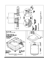
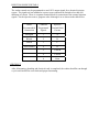
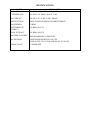
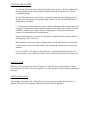
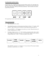
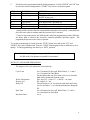
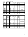
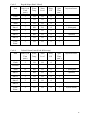
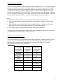
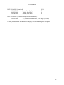
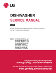
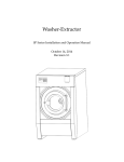
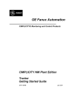
P/N 8514-081-001,
75LB CAPACITY
COMPUTER CONTROL
OPL WASHER
THE
DEXTER
COMPANY
OWNER'S BOOKLET
INSTALLATION & OPERATION
INSTRUCTIONS
Please read this information and retain for reference.
WARNING - THIS WASHER IS EQUIPPED WITH DEVICES AND FEATURES RELATING TO ITS SAFE
OPERATION. TO AVOID INJURY OR ELECTRICAL SHOCK, DO NOT PERFORM ANY SERVICING
UNLESS QUALIFIED TO DO SO.
IT IS THE RESPONSIBILITY OF THE OWNER TO CHECK THIS EQUIPMENT ON A FREQUENT
BASIS TO ASSURE ITS SAFE OPERATION.
A machine should not be allowed to operate if any of the following occur:
- Excessively high water level.
- If machine is not connected to a properly grounded circuit.
- If the door does not remain securely locked during the entire cycle.
- Vibration or shaking from an inadequate mounting or foundation.
WARNING - FOR SAFETY
1.
2.
3.
4.
5.
6.
Always shut off power and water supply before servicing.
Do not overload the washer.
Do not open door when cylinder is in motion or it contains water.
Do not bypass any safety devices of this washer.
Do not use volatile or flammable substances in or near this washer.
Keep all panels in place. They protect against shock and injury and add rigidity to the washer.
PREVENTIVE MAINTENANCE REQUIREMENTS
DAILY
- Check that the loading door remains securely locked and cannot be opened during the entire cycle.
- Check the water connections for leaks.
- Clean the top and sides of the cabinet to remove residue.
- Clean the soap dispenser and lid.
- Check the drain valve for leaking and that it opens properly.
- Check the loading door for leaks. Clean the door seal of all foreign matter.
- Leave the loading door open to aerate the washer when not in use.
QUARTERLY
- Make sure the washer is inoperative by switching off the main power supply.
- Check the V-belts for wear and proper tension.
- Clean lint and other foreign matter from around motor.
- Check all water connections for leaks.
- Wipe and clean the inside of the washer and check that all electrical components are free of moisture and dust.
- Remove and clean water inlet hose filters. Replace if necessary.
- Check anchor bolts - retighten if necessary
IMPORTANT: Replace any and all panels that were removed to perform daily and/or quarterly maintenance.
THE
DEXTER
COMPANY
INSTALLATION INSTRUCTIONS
All washers must be installed in accordance with all local, state and national building,
electrical, plumbing and other codes in effect in the area.
WARNING - THESE INSTALLATION AND SERVICING INSTRUCTIONS
ARE FOR USE BY QUALIFIED PERSONNEL ONLY. TO AVOID INJURY
AND ELECTRICAL SHOCK DO NOT PERFORM ANY SERVICING
OTHER THAN THAT CONTAINED IN THE OPERATING
INSTRUCTIONS, UNLESS QUALIFIED.
FOUNDATION REQUIREMENTS
This machine is designed for use on or over bare concrete floor - not to be used above
combustible flooring. The washer must be securely bolted and grouted to a substantial concrete
floor, or mounted and grouted upon a suitable base that is securely bolted and grouted to a
substantial concrete floor. CARE MUST BE STRESSED WITH ALL FOUNDATION WORK
TO INSURE A STABLE UNIT INSTALLATION, ELIMINATING POSSIBILITIES OF
EXCESSIVE VIBRATION. All installations must be made on sound concrete floors, 8 inches
(200 mm) or thicker. Anchor bolts or expansion anchors must be of a quality grade and a
minimum of 3/4-inch (19 mm) diameter. Six bolts are required to mount the washer to the steel
base or concrete pad.
MOUNTING
A concrete pedestal or steel-mounting base that elevates the machine approximately 4 inches
(100 mm) above the floor level is recommended to provide easy access to the loading door.
Allow a minimum of 24 inches (600mm) of clearance behind the rear of the machine, to provide
access for motor removal. Refer to Fig. 1-1 and 1-2 for machine bolt-down dimensions.
If an elevated concrete pedestal is desired, it should be embedded into the existing floor. Anchor
bolts should be 3/4" x 8" (19 mm x 200 mm), grade 8 or better, headed by a 4 inch (10 cm)
square fish plate and should protrude 2 1/2” (64 mm) above the finished surface of the pedestal.
EXPANSION ANCHORS ARE NOT RECOMMENDED FOR USE IN CONCRETE
PEDESTALS, BECAUSE THE ANCHORS ARE TOO CLOSE TO AN EDGE, CAUSING IT
TO BREAK OUT. (See Fig. 1-1 and 1-3.)
FLOOR OUTLINE
Figure 1-1
Figure 1-2
Figure 1-3
MACHINE MOUNTING DETAIL
CONCRETE PEDESTAL MOUNTING
PLUMBING
Water supply hoses are furnished with each machine. The threaded connections on the hoses are ¾11 ½ NHT.
Separate hot and cold water lines must be provided, maintaining 30 psi to 120 psi (207 kPa to 818
kPa) water flow pressure. A 140F (60C) degree hot water supply is recommended for best washing
results.
DRAIN
The drain outlet tube at the rear of the machine is 3 inches (76 mm) in diameter. A flexible hose
material (Pt. #9242-417-003) is available to extend this draining system. Any drain hose used must
be lower than the drain valve to assure proper draining.
ELECTRICAL
WARNING
SHUT OFF POWER AND WATER BEFORE OPENING ANY SERVICE PANELS.
Dexter single/three-phase 208-240VAC 60 Hz washing machines are intended to be permanently
installed appliances. No power cord is provided. The machine should be connected to an individual
branch circuit not shared by lighting or other equipment. The connection should be sheathed in
liquid tight flexible conduit, or equivalent, with conductors of the proper size and insulation. A
qualified technician should make such connections in accordance with the wiring diagram. (Suggest
a minimum wire size of 12 ga.) (Suggest a minimum wire size of 10 ga.for Single Phase operation)
TO MAKE ELECTRICAL CONNECTIONS: Disconnect all power to the washer. Remove screw
and lift out the cover located in the upper left corner of the machine (as viewed from the back).
¾ If power is 208-240-3PH-60Hz, connect L1, L2, L3 and ground. If there is a high leg it must
be connected to L3.
¾ If power is 208-240-1PH-60Hz, connect L1, L2 and Ground.
NOTE: It is important that the grounding screw next to the power terminal block TB-1 be
connected to a good external ground.
FUSING REQUIREMENTS:
SINGLE- 25 AMP TIME-DELAY (DUAL ELEMENT) FUSE (or equivalent circuit breaker)
THREE PHASE - 20AMP TIME-DELAY (DUAL ELEMENT) FUSE (or equivalent circuit breaker)
CONTROLS TRANSFORMER: The controls transformer is located inside the control trough and
steps a range of 208 to 240 volts down to 115 volts. There are two terminals on the controls
transformer for the primary (incoming) power. Use the terminal marked “208V” for power supplies
between 208 and 220 volts. Use the terminal marked “230V” for power supplies between 221 and
240 volts.
INJECTION SOURCE DETAILS
The washer control may be programmed to send 120V output signals for a chemical injection
system. The signals are not intended as a power source and must be limited to less than 100
milliamps of current. There is a separate terminal block for connection of the external injection
signals. For the injection sources, program codes 0 through 6 are as shown in the table below.
Dexter
Recommended
Connections
Controller
Programmed
Signals
Injection
Terminal Block
Circuits
Detergent
1
A
Bleach
2
B
Starch
3
C
Sour/Softener
4
D
5
A and B
6
C and D
0
None
CHECKOUT
After all mounting, plumbing and electrical work is completed, the washer should be run through
a cycle and checked for water leaks and proper functioning.
SPECIFICATIONS
MODEL
CAPACITY
75LB WASHER
75LBS/11.5 CUBIC FT. (34.1 kg/325 l)
CYLINDER SIZE
30” DIA X 28” DEEP (76cm X 71cm)
ELECTRICAL
208-240 VAC, 60 HZ, 1 OR 3 PHASE
DRIVE SYSTEM
SOFT START REVERSING INVERTER DRIVE
WASH SPEED
43 RPM
INTERMEDIATE
EXTRACT
412 RPM (60 G’S)
FINAL EXTRACT
485 RPM (100 G’S)
MACHINE CONTROL
PROGRAMMABLE COMPUTER
WATER INLET
4 SOLENOID OPERATED VALVES
FLOW RATE: 9 TO 12 GAL/MIN EACH, 30-120 PSI
DRAIN VALVE
3” DIAMETER
STARTING THE WASHER
A. Load the clothes into the cylinder and latch the door securely. Be sure clothing does
not get caught between the door gasket and tub front when closing the door. Do not
overload the washer.
B. Select the appropriate cycle number (1 through 6) using for the load being washed.
See the cycle descriptions in the programming section. Use the UP and DOWN keys to
change the cycle number.
C. If not using a chemical injection system, add low-sudsing powdered detergent into the
“detergent” compartment of the automatic dispenser on the top of the washer. If desired
add fabric softener to the “fabric softener” compartment. Use the amount of fabric
softener as recommended by the manufacturer.
If liquid wash products are used in the “detergent” compartment, they must be added at
the beginning of the wash cycle.
If the machine is set for pre-wash, washing products can be added to the round opening
of the dispenser or put in with the clothes when loading the cylinder before starting the
machine.
D. Press START. The display will go blank for a moment and then display the cycle
time in minutes. The clothes door will lock and remain locked until the end of the cycle.
END OF CYCLE
When the cycle is complete the time will display “0” until the door is opened and a 5-second
tone will sound. The door can now be opened. Leave the clothes door open when the machine is
not in use.
SAFETY DOOR LOCK
This machine is equipped with a Safety Door Lock that prevents opening the door for 2 to 3
minutes if the power is interrupted. This safety feature cannot be bypassed.
PROGRAMMING INSTRUCTIONS:
Programming can be accomplished manually using the machine controls or by connecting to the
machine control using a PDA (personal digital assistant). For instructions on using a PDA with
this washer control, please contact your local Dexter distributor. Please read below for manual
programming instructions.
The keypad layout for the washer control is shown above.
Wash Cycle Programming
1.
Turn on the power to the washer.
2.
Turn the Run/Program key to the Program position. Display will show “C O” and the “ADD
BLEACH” light will blink and will continue to blink during the programming mode.
3.
Press the “DOWN” or “UP” buttons to select which cycle to alter. When the desired cycle
number is displayed, press “START”.
4.
The display should now show a “b”. The “b” and the cycle indicator lights indicate which
bath is being selected to alter. Press the “UP” and “DOWN” buttons to select a bath to
change and then press “START”. The indicator lights are shown below.
FLUSH
PRE
WASH
WASH
RINSE
FINAL
RINSE
SPIN
When “RINSE” is selected, “b r1” through “b r4” may be selected. There may be multiple
rinses that are indicated by r1, r2, r3 and r4.
10
5.
Each bath can be programmed with the following options. Use the “DOWN” and “UP” keys
to select the desired setting and the “START” key to move to the next option.
DISPLAY
Ct **
t **
FUNCTION
Tumble Time
Water Temperature
L **
dF *
S **
IS *
Water Level
Type of Fill
Spin Time
Injection Source
OPTIONS
Two-digit amount of time in minutes.
HH for hot, CH for warm, CC for cold
and EE for no water.
Lo for low, Hl for high.
d for delayed fill, t for timed fill.1
Two-digit amount of time in minutes.
Single digit code indicating injector signal(s).2
1
A delayed fill will pause the time count until the selected level is reached. A timed fill will
allow the time count to continue until the selected level is reached.
2
Codes for injections sources are defined at the end of the programming section. When the
No Water bath is selected, the electronic controller prohibits injection signals. The
programmed injection source value is ignored.
To exit the programming of a bath, press the “STOP” button once and use the “UP” and
“DOWN” keys select another bath. Press the “STOP” button again to select a different cycle to
change. To end programming, turn the key to “RUN” position
Note: The Wash Cycle programming mode will automatically exit and return to
the Idle mode if no buttons are pushed for one minute.
WASH CYCLE PARAMETER RANGES
The range of each cycle parameter is shown below:
Cycle Time
Water Temperature
Water Level
Delay Fill
Spin Time
Injection Source
0 to 15 minutes for Prewash, Wash, Rinse1, 2, 3 and 4
1 to 15 minutes for Final Rinse
For the bathes that can, if the time is set to zero, then the
bath will be eliminated from the cycle.
HH – hot, CH – warm, CC – cold, EE – no water
HI – high, LO – low
The selections are “d” for delay the bath time until water
level is reached or “t” to count down bath time during the
fill.
0 to 10 minutes for Prewash, Wash, Rinse, 2, 3 and 4
1 to 10 minutes for Final Spin
0 to 6
11
Cycle 1
Sheets & Pillowcases (Health Care)
Bath
Bath Cycle
Time
(min.)
Water
Temp.
Water
Level
Delay
Fill
Spin
Time
(min.)
Injection Source
Flush
3
CH
HI
d
Prewash
2
CH
HI
d
Wash
7
HH
LO
d
1 (Detergent)
Rinse 1
7
HH
LO
d
2 (Bleach)
Rinse 2
2
CH
HI
d
Rinse 3
2
CH
HI
d
4
CH
LO
d
4
4 (Sour/Soft)
Spin
Time
(min.)
Injection Source
1
Rinse 4
Final
Rinse
Cycle 2
Towels / Pads / Diapers (Health Care)
Bath
Bath Cycle
Time
(min.)
Water
Temp.
Water
Level
Delay
Fill
Flush
3
CH
HI
d
Prewash
2
CH
HI
d
Wash
7
HH
LO
d
Rinse 1
1
HH
HI
d
Rinse 2
7
HH
LO
d
Rinse 3
2
CH
HI
d
Rinse 4
2
CH
HI
d
Final
Rinse
4
CH
LO
d
1 (Detergent)
2 (Bleach)
1
5
4 (Sour/Soft)
12
Cycle 3
Bath
White Towels (Hotel / Motel)
Bath Cycle
Time
(min.)
Water
Temp.
Water
Level
Delay
Fill
Wash
7
HH
LO
d
Rinse 1
1
HH
HI
d
Rinse 2
7
HH
LO
d
Rinse 3
2
CH
HI
d
Rinse 4
2
CH
HI
d
Final
Rinse
4
CH
LO
d
Spin
Time
(min.)
Injection Source
Flush
Prewash
Cycle 4
1 (Detergent)
2 (Bleach)
1
5
4 (Sour/Soft)
Spin
Time
(min.)
Injection Source
Guest Laundry (Hotel / Motel or Health Care)
Bath
Bath Cycle
Time
(min.)
Water
Temp.
Water
Level
Delay
Fill
Flush
3
CH
HI
d
Wash
7
HH
LO
d
Rinse 1
2
HH
HI
d
Rinse 2
2
CH
HI
d
Rinse 3
2
CH
HI
d
4
CH
LO
d
Prewash
5
(Detergent/Bleach)
Rinse 4
Final
Rinse
4
4 (Sour/Soft)
13
Cycle 5
Rags & Mops (Hotel / Motel)
Bath
Bath Cycle
Time
(min.)
Water
Temp.
Water
Level
Delay
Fill
Flush
3
CH
HI
d
Prewash
2
CH
HI
d
Wash
2
CH
HI
d
Rinse 1
7
HH
LO
d
Rinse 2
2
HH
HI
d
Rinse 3
7
HH
LO
d
Rinse 4
2
CH
HI
d
1
Final
Rinse
2
CH
LO
d
5
Cycle 6
Spin
Time
(min.)
Injection Source
1 (Detergent)
2 (Bleach)
Colored Cotton Linen (Food & Beverage)
Bath
Bath Cycle
Time
(min.)
Water
Temp.
Water
Level
Delay
Fill
Spin
Time
(min.)
Injection Source
Flush
2
CH
HI
d
Wash
10
HH
LO
d
1 (Detergent)
Rinse 1
7
HH
LO
d
2 (Bleach)
Rinse 2
2
CH
HI
d
Rinse 3
2
CH
HI
d
4
CH
LO
d
Prewash
1
Rinse 4
Final
Rinse
4
6 (Sour/Starch)
14
RAPID ADVANCE MODE
To enter the Rapid Advance mode, turn the key counter-clockwise (CCW). The Rapid Advance
setting is not marked next to the key, but turning the key CCW until it stops selects this mode.
The Rapid Advance mode can be entered from either the Idle mode or during the cycle. If the
cycle has not yet started, press the “START” button. To rapid advance to the next step in the
wash cycle, push both the “UP” and “START” buttons at the same time. The display will show
an “Ad” (advance) in the display. The washer will advance to the next bath segment. The water
will drain before the advance will occur and the time displayed may not be accurate.
Notes:
• The indicator lights will show to which segment the cycle has been advanced.
• The cycle will continue in rapid advance mode even if the key is turned to “RUN” and/or
removed.
• Rapid advance cannot skip the final 1-minute tumble of the cycle, and the door lock may
remain activated for a couple minutes after the cycle has been completed.
• The chemical injection signals will not operate in Rapid Advance mode.
To end the cycle and exit the Rapid Advance mode without waiting for the time to count down,
push and hold the STOP button for 5 seconds or more.
INJECTION SOURCE DETAILS
The washer control may be programmed to send output signals for a chemical injection system.
There is a separate terminal block for connection of the external injection signals. For the
injection sources, program codes 0 through 6 are as shown in the table below. See the
ELECTRICAL section for more information.
Dexter
Recommended
Connections
Controller
Programmed
Signals
Injection
Terminal Block
Circuits
Detergent
1
A
Bleach
2
B
Starch
3
C
Sour/Softener
4
D
5
A and B
6
C and D
0
None
15
ACCESSORIES
INSTALLATION: (Furnished)
9990-027-011
Hose, Water Supply
8641-242-000
Washer, Inlet Hose
9565-003-001
Strainer, Inlet Hose
QTY.
4
4
8
INSTALLATION: (Available through Dexter Distributor):
9242-417-003
3” (76 mm) Flex Drain Hose, 10 ft. length (3 meters)
Contact your distributor or The Dexter Company if a steel-mounting base is required.
16