1
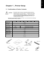
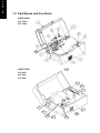
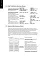
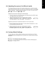
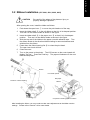
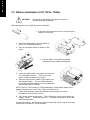
E
N
G
L
I
S
H
User’s Manual
CLP 1001, 2001
CLP 6001, 6002, 6401
CLP 7201e, 7202e
E
N
G
L
I
S
H
"DESIGNED AND MANUFACTURED TO BE EQUIVALENT TO EUROPEAN STANDARD FOR ITE,
EN60950."
CE marking shows conformity to the following criteria and provisions:
Low Voltage Directive (73/23/EEC)/EN60950
EMC Directive (89/336/EEC)/EN55022 & EN50082-1
The following symbols are used in this manual.
WARNING
Indicates a situation which, if not observed and handled
CAUTION
Indicates a situation which, if not observed and handled
properly, could result in death or serious injury.
properly, could result in injury.
For the safe operation of your printer, please read the following
important operation and safety instructions carefully:
1.
Read all of these instructions and save them for later reference.
2.
Follow all warnings and instructions marked on the product.
3.
Unplug this product from the wall outlet before cleaning. Do not use liquid or aerosol
cleaners, thinner, trichloroethylene, benzine, ketone or similar chemicals. Instead use a
damp cloth for cleaning, when the printer is disconnected from the mains supply.
4.
Do not use this product near water or where a chemical reaction can occur such as in a
laboratory or where there is a lot of oil, dust, salt or iron particles.
5.
Do not place this product on an unstable cart, stand or table. The product may fall,
causing serious damage to the product and people around it.
6.
Slots and openings on the cabinet and the back or bottom are provided for ventilation.
7.
To ensure reliable operation of the product and to protect it from overheating, do not
block or cover these openings. The openings should never be blocked by placing the
product on a bed, sofa, rug or other similar surface. This product should never be
placed near or over a radiator or heat source. This product should not be placed in a
built-in installation unless proper ventilation is provided.
8.
This product should be operated from the type of power source indicated on the marking
label. If you are not sure of the type of power available, consult your dealer or local
power company.
9.
This product is equipped with a three-pronged plug, a plug having a third grounding pin.
This plug will only fit into a grounding-type power outlet. This is a safety feature. If you
are unable to insert the plug into the outlet, contact your electrician to replace your
obsolete outlet. Do not defeat the safety purpose of the grounding-type plug.
10. Do not allow anything to rest on the power cord. Do not locate this product where the
cord will be walked on. Do not pull on the power cord or data cables or keep them under
tension.
11. If an extension cord is used with this product, make sure that the total of the ampere
ratings on the products plugged into the extension cord do not exceed the extension cord
ampere rating. Also, make sure that the total of all products plugged into the wall outlet
does not exceed 7.5 amperes for 220-240V outlet.
12. Never push objects of any kind into this product through cabinet slots as they may touch
dangerous voltage points or short out parts that could result in a risk of fire or electric
shock. Never spill liquid of any kind on the product.
- i-
E
N
G
L
I
S
H
E
N
G
L
I
S
H
13. Except as explained elsewhere in this manual, don't attempt to service or disassemble
this product yourself. Opening and removing those covers that are marked "Do Not
Remove" may expose you to dangerous voltage points or other risks. Refer all servicing
on those compartments to service personnel.
14. The mains plug on this equipment must be used to disconnect mains power. Please
ensure that the socket outlet is installed near the equipment and shall be easily
accessible.
15. Unplug this product from the wall outlet and refer servicing to qualified service personnel
under the following conditions:
a.
When the power cord or plug is damaged or frayed.
b.
If liquid, aerosol chemicals or other chemicals have been spilled into the product.
c.
If the product has been exposed to rain or water or excessive humidity.
d.
If the product does not operate normally when the operating instructions are
followed. Adjust only those controls that are covered by the operating
instructions since improper adjustment of other controls may result in damage and
will often require extensive work by a qualified technician to restore the product to
normal operation.
e.
If the product has been dropped or knocked or the cabinet has been damaged.
f.
If the product exhibits a distinct change in performance, indicating a need for
service.
16. Discard or safely store the plastic packing bag. This bag should be kept away from children.
If the bag is pulled over child’s head, it may cause suffocation.
17. Make sure if you open the top cover, it is opened all the way. If only partially open, the
cover could slam shut, possibly causing injury.
18. When the cover is open, be careful of the corners of cover. They could cause injury.
19. Do not open the printer during printing.
20. Operate the control panel properly. A careless, rough handling may cause problems or
malfunction. Do not use such sharp-edged tool as a ballpoint for operation.
21. If a problem occurs during printing, stop the printer immediately and unplug the power
cord from the outlet.
22. The contents of this manual may be changed without prior notice.
23. Reproduction, transfer, or transmission of the contents of this manual without prior
consent is strictly prohibited.
24. We are not liable for any damage resulting from the use of the information contained
herein, regardless of errors, omissions, or misprints.
25. We are not liable for any problems resulting from the use of optional products and
consumable supplies other than the designated products contained herein.
26. We are not liable for any damage caused by user's erroneous use of the printer and
inadequate environment.
27. Data residing in the printer is temporary. Therefore, all data will be lost if power is
lost. We are not liable for any damage or loss of profits caused by data loss due to
failures, repairs, inspections, etc.
28. Please contact us if there are any mistakes or ambiguities within this manual.
29. If there are missing or incorrectly collated pages in this manual, contact us to obtain
a new manual.
30. Trademarks or registered trademarks of other companies and products are included
in this manual. Citizen acknowledges all trademarks.
E
N
G
L
I
S
H
Table of Contents
Chapter 1 – Printer Setup ...................................................................................................................... 1
1.1
Confirmation of Carton Contents ........................................................................ 1
1.2
Part Names and Functions ................................................................................. 2
1.3
Connection to Power .......................................................................................... 5
1.4
Connection to a Computer.................................................................................. 5
Chapter 2 – The Control Panel.............................................................................................................. 6
2.1
Control Panel ..................................................................................................... 6
2.2
Normal Operating Mode ..................................................................................... 6
2.3
Printer Setup Mode ............................................................................................ 6
2.4
Self-Test Mode And Hex Dump........................................................................... 8
2.5
System Maintenance Mode ................................................................................ 8
2.6
Adjusting the sensors for different media............................................................ 9
2.6
Factory Default Settings ..................................................................................... 9
Chapter 3 – Paper & Ribbon................................................................................................................10
3.1
Media Installation ..............................................................................................10
3.2
Ribbon Installation (CLP 2001, 6001, 6002, 6401).............................................11
3.3
Ribbon Installation (CLP 7201e, 7202e) ............................................................12
3.4
Media Thickness Adjustments ...........................................................................13
3.5
Media Width Adjustments ..................................................................................14
3.6
Ribbon Tension Adjustments (CLP 2001, 6001, 6002, 6401) .............................15
3.7
Ribbon Tension Adjustments (CLP 7201e, 7202e).............................................16
3.8
Adjustable Media Sensor...................................................................................17
Chapter 4 – Troubleshooting ..............................................................................................................18
4.1
Error Messages .................................................................................................18
4.2
Print Troubleshooting.........................................................................................19
4.5
Interface Troubleshooting ..................................................................................20
- iii -
E
N
G
L
I
S
H
Chapter 1 – Printer Setup
1.1 Confirmation of Carton Contents
CAUTION
Be careful when moving or carrying the printer and when
taking the printer out of the carton. The printer may cause
injury or property damage if dropped. Be sure to grip the
printer housing tightly when taking it out of the carton. Do
not grip the foam or cardboard packaging that may break,
causing the printer to drop.
Depending on the version of printer you have, you should check the following
items are present with your printer:
CLP Model
1001
2001
6001
6002
Power Cord
1 unit
Roll Holder
1 unit
Roll Guide
Paper Holder
Mounting Screws
7201e
7202e
1 unit
1 pair
Not required, not included
4 screws
Not required, not included
Paper Core
1 unit
User Manuals
1 set
Sample Media
1 pack
Sample Ribbon
1 roll
Cleaning Pen
1 pen
CD ROM
6401
Optional – a CD with additional drivers and manuals may be included in
the box
Paper core
User’s manual
Power cord
Paper Holder & Screws
Sample Media
Ribbon
Paper Core
Cleaning Pen
Roll guide
E
N
G
L
I
S
H
1.2 Part Names and Functions
INSIDE VIEW:
CLP 7201e
CLP 7202e
14
1
INSIDE VIEW:
CLP 6001
CLP 6002
CLP 6401
5
6
7
2
3
4
13
14
8
9
E
N
G
L
I
S
H
INSIDE VIEW:
1
CLP 1001
CLP 2001
4
3
7
5
6
n
2
14
8
9
(1)
Cover: Opens to allow loading of the
media and ribbon.
(2)
Control panel: To set the printer
configuration settings.
(3)
Ribbon holder: To attach the source or
unused ribbon (not on CLP 1001)
(4)
Ribbon winder: To wind the ribbon after
printing (not on CLP 1001)
(5)
Roll holder: Holds the roll of media.
(6)
Roll guide: Guides the roll of media. This
is adjusted according to the width of the
media.
(7)
(8)
Media holder: Holds the roll holder and
media. External bracket on 1001 and
2001.
Open lever: To swing the printhead out of
the way when loading the media or
cleaning the printhead.
(9)
13
Media Width adjustment knob
Allows you to adjust for different media
widths using the window. See 14
(10) Media arm
Holds down the media. The adjustable,
movable media sensor inside (CLP 6001,
6401, 7201e) detects the media position.
(11) Media arm open lever
Releases the media arm (not on 1001)
(12) High resolution front sensors
Fixed media sensor (6401,7201e, 7202e)
(13) Offset check window
Allows you to see the printhead pressure
adjustment (see 9 above)
(14) Media width adjustment window
Allows you to see the media with
adjustment (see 9 above)
E
N
G
L
I
S
H
FRONT VIEW
n Control panel
The printer has two LED indicator lights and an LCD screen that
displays printer messages.
1. LEDs : One LED is the power indicator and
the other is the error indicator.
Hinge
LCD
2. LCD: Displays the current printer status,
configuration settings, or an error message.
LEDs
3. Control keys: The Pause, Feed and Stop keys
are arranged from left to right and are used to
facilitate printer operation. (For details, see
Chapter 2 Control Panel.)
4. Cover hinges: The cover hinges are used to
hold the cover as far as you have opened it.
Control keys
CONNECTOR LOCATIONS
5
4
PCMCIA memory card cover
1
3
6
CLP 1001, 2001, 6001, 6002, 6401
CLP 7201e, 7202e
(1)
RS232C serial interface
(4)
Power switch
(2)
USB interface (CLP 7201e, 7202e only)
(5)
AC power inlet (for mains power cord)
(3)
Parallel Interface
(6)
PCMCIA memory card cover
E
N
G
L
I
S
H
1.3 Connection to Power
CAUTION
Always use an AC outlet that accepts a
three-pronged plug. Otherwise, static electricity
may be generated and there will be danger of
electric shock.
Connect to an AC outlet as follows:
1
Check that the power switch on the printer is set to OFF.
2
Connect the connector of the power cord to the power inlet on the printer.
3
Insert the plug of the power cord in the AC outlet.
1.4 Connection to a Computer
An interface cable is necessary for connecting the printer to a computer.
To connect them, proceed as follows:
1
Turn off both power switches of the printer and the computer.
2
Connect the connector of one end of the interface cable to the interface
connector at the lower side of the printer and secure it correctly.
3
Connect the connector of the other end of the interface cable to the interface
connector on the computer and secure it correctly.
Serial interface
Serial interface
USB interface
Parallel interface
Parallel interface
CLP 1001, 2001, 6001, 6002, 6401
CLP 7201e, 7202e
E
N
G
L
I
S
H
Chapter 2 – The Control Panel
2.1 Control Panel
The control panel on the front of the printer consists of three control keys
(Pause, Feed and Stop), two LED indicator lights (Power, Error) and a LCD
message screen. On the left side of the control panel there are three
adjustment controls (paper gap, black line and LCD contrast).
(1) LCD: Displays the current printer status,
configuration settings, or an error message.
(2) LEDs: The green LED indicator shows that
the power is turned on. The red LED lights
when there is an error.
(3) PAUSE key: Temporarily pauses printing.
(4) FEED key: Feeds the media.
(5) STOP key: Stops the printer operating.
(6) Media gap adjustment control: To adjust
the media gap sensor sensitivity.
See
section 2.6.
(7) Black mark adjustment control: To adjust
the black mark sensor sensitivity.
See
section 2.6.
(8) LCD contrast adjustment control: To
adjust the LCD contrast if this is faint.
2.2 Normal Operating Mode
When the power is turned on, the printer enters normal operating mode.
control keys function as follows:
The
n
Pause key: Temporarily pauses printing. "Pause" is displayed on the LCD
screen. If pressed during printing, printing will stop after the current label is
printed. Press the Pause key again to resume printing.
n
Feed key: Advance to the top of the next label. When using continuous
paper, make sure the Sensor selection is set to ContinuP or a Paper error will
result.
n
Stop key
With this key, the operator can stop and cancel the current print job.
Pressing the Stop key during printing stops the printing immediately.
Pressing the Stop key again cancels the print job.
2.3 Printer Setup Mode
The print setup mode allows you to change printer operations such as direct
thermal or thermal transfer printing, tear mode, etc.
To enter the printer setup mode, press and hold down the Pause key then press
the Feed key and release both keys. The functions of the control keys are
described below.
Changes to the printer configuration are stored in “nonvolatile memory”. This
guarantees that the printer configuration is maintained even after the power is
turned off.
n Pause key:
Selects the mode.
n Feed key:
Selects the mode item.
n Stop key:
Saves the selection contents and returns the printer to the
normal operating mode.
The functions indicated by an ♦ character work on the CLP 1001, 2001, 6001, 6002
and 6401 printers. Those with a ● character work on the CLP 7201e and 7202e
printers
LCD Indication
Function Description
♦●
Transfer
DirectTM
Direct thermal or thermal transfer
printing
♦
Peel OFF
Peel ON
Enable or disable peeler function
♦
Cut OFF
Cut ON
Enable or disable cutter function
♦
Tear OFF
Tear ON
AfterPrt
PeelWait
AutoCut
TearBar
NoAction
Edge
Reflect
ContinuP
●
HeadHeat
Heat 01
Heat 30
Set the printhead temperature
●
PrintSpd
PSpeed 2
PSpeed 7
Set the print speed in inches/second
●
Feed Spd
FSpeed 2
FSpeed 7
Set the feed speed in inches/second
●
Back Spd
BSpeed 2
BSpeed 7
Set the back feed speed in inch/sec
●
Vert Adj
V-2.00in
V+2.00in
Vertical label position adjustment.
●
HorizAdj
H-2.00in
H+2.00in
Horizontal label position adjustment.
●
StopPos
S-2.00in
S+2.00in
Stop position adjustment
●
SetLckOF
SetLckON
●
♦●
Enable or disable tear-off function
“AfterPrint” functions. Set the
operation of the printer after the
label has been printed.
Select media gap detection method
either “edge” (label gap), reflective
or continuous media
Settings Lock Off/On. When “on”,
causes the printer to ignore
commands changing the above
values set on the control panel.
E
N
G
L
I
S
H
E
N
G
L
I
S
H
2.4 Self-Test Mode And Hex Dump
The printer enters the self-test
mode when the Feed key is
pressed and held down while
turning the printer on.
If the Feed key is held down
for more than four seconds,
the printer assumes
continuous media is installed.
The printer performs a
two-page self-test print then
enters the Hex Dump or Data
Dump mode (prints out the
communication data by ASCII
code).
The printer returns to the
normal operating mode only
when the power is turned off.
2.5 System Maintenance Mode
The printer enters the system maintenance mode when the Pause, Feed and
Stop keys are pressed and held down simultaneously while turning the printer on.
The printer enters the communication parameter setting, system setups and
paper gap and black line sensor sensitivity adjusting mode.
The mode is selected with the Pause key and the mode item is selected with the
Feed key. Changing of the contents is executed as soon as they are displayed
on the screen. Pressing the Stop key returns the printer to the normal operating
mode.
LCD Indication
Function Description
38400bps
Select baud rate between 38,400
bps down to 300 bps.
9600bps
19200bps
8 bits
7 bits
Select 8 or 7 data bits
NativeOF
NativeON
Select Native Off or Native On
mode.
fVirtual
fReal
Select distance of media sensor
relative to the printhead position.
Cmnd STD
Cmnd AS4
AjSensOF
AjSensOn
Select between fixed media and
adjustable sensor when installed.
PE x.xxV
BL x.xxV
See through or black line sensor
checking mode. See Section 2.6
Cmnd RST
Select between standard command
set, AS400 mode or raster mode.
E
N
G
L
I
S
H
2.6 Adjusting the sensors for different media
The voltage setting mode, part of the system setting mode, is used to correctly
adjust the see-through or black line sensors for the particular type of media being
used in the printer. The ideal voltage is between 3.0v and 3.3v for both the PE
(paper end or gap) and BL (black line) modes.
Adjustment procedure for label paper (with label gap):
1
Remove a label from the backing paper (liner) and set the liner ONLY under
the media sensor (see section 3.4).
2
Adjust the paper gap value on the control panel to a value
between 3.0 volts and 3.3 volts. Adjustment is made using
the upper adjuster on the control panel. See section 2.1
PE 3.05v
Adjustment procedure for media with a black line on the reverse side:
1
Set the unmarked part of the media – the area without the black line - under
the media sensor (see section 3.4).
2
Adjust the black line value on the control panel to a value
between 3.0 volts and 3.3 volts. Adjustment is made using
the middle adjuster on the control panel. See section 2.1
BL 3.05v
2.6 Factory Default Settings
To return the print to Factory Default settings, press and hold down the Pause,
Feed and Stop keys simultaneously for more than four seconds whilst turning on
the power.
S Maint
The display will first show “S Maint”
S/I Init
You must keep the buttons held down until the LCD displays the
message “S/I Init”
E
N
G
L
I
S
H
Chapter 3 – Paper & Ribbon
3.1 Media Installation
CAUTION
Take care not to trap lose clothing in the mechanism of the
printer when it is closed!
The printer is designed for easy loading of paper and ribbon.
detailed guide for first-time users:
1
2
3
Push down the open lever ①
to release the print head and
lift it out of the way
However, here is a
②
⑩
Roll
①
Push down the sensor arm
lever ③ to move the sensor
arm ② out of the way (not
present on the CLP 1001)
⑤
Slide the black plastic media
guide ⑤ over the media
support bar ④ and insert the
support bar through the roll of
media being installed.
④
⑥
4
Rest the media support bar in
③
to the paper holder ⑥ and
slide the roll guide ⑤ to the
width of the roll paper. The
paper roll should be pushed
against the side nearest the top cover hinges ⑥*, but should still be free to
move easily.
5
Place the media on the main printer chassis, with the left side of the media
against the fixed paper guide ⑧. Slide the small moving paper guide ⑦ to
maintain the correct media width slightly in
Roll paper
contact the right edge of the media so that
⑤
the paper does not skew.
6
Push down the sensor arm ② until the lever
hook is locked (not CLP 1001).
7
Roughly align the leading edge of the paper
with the tear-off plate ⑨.
8
Close the top mechanism by pressing down
the ribbon bearing flat ⑩ to close the print
head. The mechanism will lock closed.
9
Close the cover.
10 Turn on the power to the printer. The LCD
screen on the control panel will display "On
line." Press the Feed key. The paper will
advance to the next label and stop there.
④
⑥
⑥
③
⑦
⑧
⑨
Notch
alignment
for
3.2 Ribbon Installation (CLP 2001, 6001, 6002, 6401)
CAUTION
Be careful of the edges of the plates so injury or
property damage is possible.
After opening the cover, install the ribbon as follows:
1
Push down the open lever ① to move the print head out of the way.
2
Insert the ribbon shaft ⑪ in the roll ribbon so that it is in its deepest position.
Then set it in the ribbon holder as shown in the figure.
3
Insert the ribbon shaft ⑫ in the paper core ⑬ so that it is in its deepest
position. Then set it in the ribbon winder as shown in the figure.
4
Stick the top end of the ribbon to the paper core with adhesive tape. Turn
the ribbon winder in the direction ribbon winding to remove slackness and
wrinkles from the ribbon.
5
Press down the ribbon bearing flat ⑩ to close the print head.
The open lever hook will lock.
6
Close the cover.
7
Turn on the power to the printer. The LCD screen on the control panel will
display "On line." Press the Feed key. The paper will advance to the next
label and stop there.
⑪
⑫
Ribbon
⑬
Print head opened
Roll paper
Direction of ribbon winding
Ribbon
①
Completion of setting paper and ribbon
After installing the ribbon, you may need to make some adjustments to the ribbon tension
settings. Please refer to section 3.6 for more details.
E
N
G
L
I
S
H
E
N
G
L
I
S
H
3.3 Ribbon Installation (CLP 7201e, 7202e)
CAUTION
Be careful of the edges of the plates so injury or
property damage is possible.
After opening the cover, install the ribbon as follows:
1
Push down the head open lever to move the print
head out of the way.
2
Insert the ribbon shaft in the roll ribbon so
that it is in its deepest position.
3
Set it in the ribbon holder as shown in the
figure.
4
Pull the ribbon from under the transfer
mechanism to the ribbon winding side.
5
Insert the ribbon shaft in the paper core so that it
is in its deepest position. Then set it in the
ribbon winder as shown in the figure.
6
Stick the top end of the ribbon to the paper core
with adhesive tape. Turn the ribbon winder in
the direction ribbon winding to remove slackness
and wrinkles from the ribbon.
NOTE: the CLP 7201e and CLP 7202e destination (used) ribbon winds in the
opposite direction to the CLP 1001, 2001 and 6000 series.
7
Close the mechanism and press down the green plastic to lock the
mechanism, then close the cover.
8
Turn on the power to the printer. The LCD screen on the control panel will
display "On line." Press the Feed key. The paper will advance to the next
label and stop there.
For specialist ribbons, adjustments to the auto-tensioning system may be necessary.
Please refer to section 3.7 for more details.
E
N
G
L
I
S
H
3.4 Media Thickness Adjustments
CAUTION
Ensure the print head adjustments are made correctly
according to the type of media (thickness & width).
Incorrect adjustments can cause failure of the print
head.
The offset adjustment screw allows you to adjust the printer depending on the
thickness of media being used.
Offset adjustment screw (M3)
Offset verification window
The relationship between the offset adjustment screw and the print head
heating element is shown below:
a) Print head position for labels (regular media)
Offset adjustment
screw
Offset verification window
a
Heating element
b) Print head position for tags or card (thicker media)
Offset adjustment
screw
Heating element
Offset verification window
b
E
N
G
L
I
S
H
3.5 Media Width Adjustments
CAUTION
Ensure the print head adjustments are made correctly
according to the type of media (thickness & width).
Incorrect adjustments can cause failure of the print
head.
Adjustments may be needed if paper with different width is used. Print
darkness is affected by the amount of pressure on the print head so it must
be adjusted with the head pressure adjustment screw if necessary.
The pressure on the right side of the print head, viewed from the front panel,
is adjusted by turning the head pressure adjustment screw. Turning the
screw clockwise decreases the pressure, and turning the screw
counterclockwise increases the pressure.
Normally, the pressure on the left and right sides of the print head has
already been adjusted to equal loads at the factory. The check marks are
located under the upper frame window.
Adjustments are needed in the following cases:
1)
When print on the left side is too light, turn the head pressure adjustment
screw clockwise.
2)
When print on the right side is too light, turn the head pressure
adjustment screw counterclockwise.
3)
When paper of smaller width is used:
In this case, the contact between the print head and the platen becomes
large, so the motor will have a heavy load and the print head may scrape
the platen. To avoid this, turn the head pressure adjustment screw
clockwise to decrease the pressure on the right side of the print head.
Verification
window
Paper width
Right head
pressure
1 inch
0 kgf
2 inches
0.5 kgf
3 inches
1 kgf
4 inches
2.4 kgf
Upper frame window
Head pressure adjust-screw
Used for adjustments when
ribbon wrinkles or skews with
paper width of 4 inches
Factory setting
Note:
These values are just for reference.
E
N
G
L
I
S
H
3.6 Ribbon Tension Adjustments (CLP 2001, 6001, 6002, 6401)
When the ribbon slips or wrinkles during printing, adjust the ribbon tension. The
printer has already been factory set with the ribbon width of 114 mm. When
using ribbon with a different width, adjust it according to the following procedure:
a)
Hold the ribbon roll with one hand so that it does not turn.
b)
Slightly push the knob toward the ribbon roll with the other hand and rotate
the knob until the stopper comes to the desired position.
c)
Gradually release the knob so that the stopper fits in the groove on the knob.
Set values to each ribbon width:
Ribbon width
Adjustment when ribbon slips
25.4 mm (1 in)
50.8 mm (2 in)
76.2 mm (3 in)
101.6 mm (4 in): factory setting
d)
Ribbon winding
section
5
4
3
2
1
After printing, check for ribbon wrinkle or slippage.
further according to the following procedure:
Ribbon feed
section
5
4
3
2
1
If it occurs, adjust it
(1)
When the ribbon wrinkles, the tension on the ribbon winding section
should be increased.
(2)
When the ribbon slips, the tension on the ribbon feed section should
be decreased. If the problem is not resolved even when the tension
on the ribbon feed section is set to 3, the tension on the ribbon
winding section should be increased.
If ribbon problems are not resolved, consult our service personnel.
Ribbon feed section
Ribbon winding section
Variable knob
Mild
Strong
Strong
Mild
Tension
Mild
Strong
E
N
G
L
I
S
H
3.7 Ribbon Tension Adjustments (CLP 7201e, 7202e)
The CLP 7201e and 7202e feature an automatic ribbon tensioning system to keep
even tension during a print run.
If you receive a “Ribbon
Out” error message during
normal operation, you may
need to adjust the
tensioning system.
With some specialist
ribbons and occasionally
with narrow width ribbons,
the base level of the ribbon
tensioning system may
need to be adjusted.
Easy-to-slip ribbon and media
Set the feeding section tension adjuster to the
LOW position.
Especially-easy-to-slip ribbon and media
Should the “Ribbon Out” error still occur, set the
feeding section adjuster to the SUPER LOW
position.
When ribbon is broken during printing
The ribbon may be broken if it is narrow in width
and printhead heat temperature is high. In that
case, set the mark on the feeding section to
SUPER LOW and set the mark on the winding
section to LOW by turning the adjust-knob and
adjust-screw respectively.
Note: If the problem is still not resolved, please
contact our service personnel.
E
N
G
L
I
S
H
3.8 Adjustable Media Sensor
The adjustable media sensor is standard on the CLP 6001, 6401 and 7201e
models. It can be fitted as an option to all other models.
If the printer has both a fixed sensor and an adjustable sensor installed,
remember to select the “AjSensON” setting in the control panel. See section 2.5
for more details.
Adjust-knob
70.6
192.4
Guide rail upper
37.7
Mark (Yellow)
The location of the media sensor is shown by the yellow position mark. This can
be moved from left to right using the adjustment knob. Moving the adjustment
knob will cause a click for each position change.
Remember to set the voltage levels for the new type of media as described
elsewhere in this manual.
If the printer has both a fixed sensor and an adjustable sensor installed,
remember to select the “AjSensON” setting in the control panel. See section 2.5
for more details.
E
N
G
L
I
S
H
Chapter 4 – Troubleshooting
4.1 Error Messages
When there is a problem with the printer, a buzzer sounds, and the error lamp on
the control panel lights and an error message is displayed on the LCD screen.
Some of the most common errors and corrective actions are shown below.
LCD Message
Description
Corrective actions
Head Err
Abnormal head
resistance value
The head has been damaged - contact Citizen’s
service department for a replacement printhead.
Perform a self-test to see where the head is
damage. You can cancel this error by pressing
the STOP key although printing is affected.
OverFlow
Serial Interface
Problem
Check the details and clear with the Stop key.
S/I Err
HostBusy
You may need to change your cable or
computer settings to match those of the printer.
This generally requires someone with good
technical knowledge of communication systems
T.D.Full
Pause
Pause key pressed or
pause command
received.
Press the Pause key once again to resume
printing. If the Stop key is pressed, the stored
printing contents will be lost and "on line" will
turn on.
HeadOpen
Mechanism head
open
Close the mechanism head.
PaperEnd
Paper out or paper
end or a problem with
feeding the media
such as the printer
cannot detect the end
of the media.
Install the paper or check for mis-feed.
PaperErr
M Comand
Correct the faulty setting of the paper detection
(paper gap, black line, continuous paper).
Correct the faulty parameter for paper (max.
length, continuous paper).
Some settings can be adjusted on the printer
but it is more likely the changes must be made
on the host computer.
RibonOut
Ribbon end or
incorrect tension
adjustments
Install the ribbon and check it is winding in the
correct direction.
On a 7201e and 7202e, check for the correct
base ribbon tension adjustment (section 3.7)
In direct-thermal, ensure the ribbon is disabled.
Cut Err
Auto-cutter
abnormality (such as
poor engagement)
Very carefully check and clear a jam in the
autocutter option. If this can't be cleared, turn
off the power and remove foreign matter from
the auto-cutter.
If this recurs, contact Citizen service persons.
E
N
G
L
I
S
H
4.2 Print Troubleshooting
Switch on the printer whilst holding down the FEED key until “PrntTest” is displayed.
sample output is printed on page 2.
Problem
A
Cause and remedy
Missing lines
(vertical lines)
Print head is damaged.
Contact the Citizen service
personal to obtain a replacement
and install as required.
Dropouts (light
patches)
Print head is dirty.
Check the print head
heat-generation body for dirt. If
it's dirty, wipe the surface of the
print head elements with the head
cleaning pen provided.
Platen roller is dirty.
Remove dirt or label or tape scraps
stuck to the platen roller. If they
cannot be removed, contact our
service personnel.
Printing is too
light or too dark
on one side of
the self-test
Media width adjustment
is not set correctly.
Refer to section 3.5 for more
details about adjusting the
media width settings.
Print is too light
or too dark
overall
Incorrect head pressure
adjustments
Change to the recommended type
after checking the ink ribbon and
paper maker and identification
number.
Ink ribbon and paper are
not the recommended
type.
Obtain matched ink and ribbon and
adjust printer parameters
accordingly.
Incorrect head heat
setting
Check the heat level in the
software and adjust it as
necessary.
Incorrect direct-thermal
or thermal transfer
setting.
Check whether the printer is set for
direct-thermal or thermal-transfer
printing and change it as
necessary.
E
N
G
L
I
S
H
4.3 Interface Troubleshooting
Any interfacing problems can generally be fixed by simply double checking that the
interface connectors are in the correct sockets and securely fastened.
However, for serial interfaces, we recommend the use of Citizen’s standard RS232C
serial cable for correct operation of your printer.
In case of interface errors, initially
you should replace the interface cable with a known good cable before contacting our
service personnel.
Details of Citizen’s recommended serial cables are shown below: