1
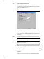
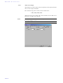
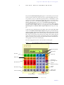
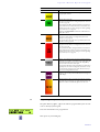
MAGIC
ISDN Standard/Triple
Telephone Hybrid
Hardware/Software Manual
.
MAGIC
ISDN
Standard/Triple
Telephone
Hybrid
Hardware/Software
Manual
.
A Publication of
AVT Audio Video Technologies GmbH
Nordostpark 12
D-90411 Nürnberg
Telephone +49-911-5271-0
Telefax +49-911-5271-100
Internet: http://www.avt-nbg.de
Email: [email protected]
Printed in Germany, April 2003
© AVT Audio Video Technologies GmbH
All rights reserved. Reproduction in
whole or in parts is prohibited without the
written consent of the copyright owner.
The information contained in this
publication is accurate to the best of AVT’
knowledge. However, AVT disclaims any
liability resulting from the use of this
information and reserves the right to
make changes without notice.
Release Date: Juli 2004
.
Content
1
CONSTRUCTION
15
2
SYSTEM DESCRIPTION
2.1
Functionality
3
PUTTING THE SYSTEM INTO OPERATION 19
3.1
Mounting
3.2
Connection to the mains supply 19
3.3
Alarm indication LEDs 20
3.4
Controls on the front side 20
3.5
Changing the fuse 20
3.6
Connecting the system
4
WINDOWS PC SOFTWARE
4.1
Hardware requirements
4.2
Connection to the PC
4.3
Operation of the system
4.4
Control elements of the windows PC software
4.5
Menu Configuration -> COM-Port
4.6
Menu File -> Exit
4.7
4.7.1
4.7.2
Menu Administration 28
Submenu System Panel 28
Submenu Software Download 28
4.8
Menu Help -> About Telephone Hybrid
4.9
4.9.1
4.9.2
Menu Configuration -> System 31
System configuration without keypad 32
System Configuration with Keypad 43
5
OPTION: MAGIC HYBRID KEYPAD 51
5.1
Working with the MAGIC Hybrid Keypad
5.2
LCD-Display
5.3
Function of the keypad.
5.4
Programming of the quick dial keys
5.5
Programming of the forwarding
A1
AUIDIO-INTERFACE ASSIGNMENT 57
A1.1
Assignment with an analogue input
A1.2
Assignment with a digital input
17
17
19
21
23
23
23
24
26
27
30
52
54
55
56
59
58
52
24
A2
INTERFACES 61
A2.1
S0 Interface 62
A2.2
RS232C-Interface 63
A2.3
TTL USER I/O Interface 63
A2.4
LSD (Keypad) Interface 64
A2.5
HSD (Relay) Interface 64
A2.6
Audio Interface 65
A2.7
A2.7.1
A2.7.2
Audio Interfaces on the optional AES/EBU/Analogue Module 65
AES/EBU Audio Interface 65
Analogue Audio Interfaces 66
A2.8
Receiver 66
A2.9
Extension Bus (internal data bus and control bus) 67
A3
TECHNICAL DATA
A4
TECHNICAL DATA MAGIC HYBRID KEYPAD 71
A4.1
Keypad 71
A4.2
LCD Display 72
A4.3
Mains power supply unit: 72
A5
GENERAL FACTS 73
A5.1
Ordering numbers
A5.2
Included in delivery 73
A5.3
Declaration of Conformity 73
69
73
INTRODUCTION
The MAGIC ISDN Telephone Hybrid system enables the forwarding of telephone calls to analogue or optional digital AES/EBU audio-interfaces. Since
the system is based on a modular construction it is possible to expand it as desired. The Basic system supports the simultaneous Hybrid-function up to
three or four callers, as well as call forwarding to a selected number.
In contrast to previous systems, great emphasis was put on using as little external wiring as possible. The system is able to realise functions such as digital
mixing of callers, digital Mix Minus, Echo-Cancelling, AGCs etc.
System configuration is carried using a simple Windows Application. The operation can either be done by this software or by the optional MAGIC Hybrid
Keypad.
PAGE 9
PAGE 10
SAFETY
Introduction
The unit described is designed to the latest technical parameters and complies
with all national and international safety requirements. It operates with a high
level of operational safety resulting from long development experience and
stringent quality control in our company.
In normal operation this equipment is safe.
There are, however, some potential sources of danger that cannot be completely eliminated.
This Operator Manual therefore contains basic safety instructions that must
be observed during system configuration and operation. The Operator Manual must be read before the system is used and the current version of the document must always be kept close to the equipment.
All safety instructions have a unifom appearance. This appearance is described in detail in the following CHAPTER.
General safety requirements
In order to keep the technically unavoidable residual risk to a minimum it is
imperative to observe the following rules:
– Transport, storage and operation of the unit/system must be under the permissible conditions only.
– Installation, configuration and disassembly must be carried out only by
trained personnel and with reference to the respective documentation.
– The system must be operated by knowledgeable and authorised users only.
– The system must not be operated unless it is in good working order.
– Any conversions or alterations to the system or parts of the system (including the software) must be carried out by qualified personnel from the
manufacturer or by expert personnel authorised by our company.
All alterations carried out by other persons lead to a complete exemption
from liability.
– The removal or disabling of safety measures, the correction of faults and
errors, and the maintenance of equipment must be carried out by specially
qualified personnel only.
– Non-system software is used at one’s own rsik. The use/installation of
non-system software can adversely affect the normal functioning of the
system.
– Only use tested and virus-free data carriers!
PAGE 11
Appereance of the safety instructions
All safety instructions include a signal word that classfies the danger and a
text block that contains descriptions of the type and cause of the danger, the
consequences of ignoring the safety instruction and the measures that can be
taken to minimise the danger. In some safety instructions, a warning symbol
is placed underneath the signal word (see TAB. 2, page 12)
Signal word
Type and cause of danger
Possible consequences of ignoring the safety instruction
Measures to minimise the danger.
Classification of danger
There are five classes of safety instructions: "danger“, "warning“, "caution“,
"notice“ and "important“. The classification is shown in the following table.
SIGNAL WORDS AND EFFECTS WHEN IGNORING THE SAFETY INSTRUCTIONS
possible
likely
definite
possible
likely
possible
likely
definite
definite
Material damage a Fault b
Minor
injury
possible
likely
definite
Serious
injury
possible
signal word
Death
likely
result
definite
TAB. 1
DANGERc
WARNING
CAUTION
NOTICE
IMPORTANT
a
damage to product or product environment
b
considerable impairment to operation
c
this danger class is not required for MAGIC ISDN Telephone Hybrid
The signal word "Note“ is also used in the Operator Manual. Text passages
marked in this way do not describe a danger, but rather contain reminders,
tips and general information to ensure optimum operation of the system.
Symbols
The following symbols are used:
TAB. 2
WARNING SYMBOL
Symbol
common usage
General warning about a danger
Important advice
!
PAGE 12
TAB. 2
Symbol
WARNING SYMBOL
common usage
Warning about a dangerous electrical voltage
The safety instructions classified as „danger“, „warning“ and „caution“ always include a warning symbol. „Notice“ and „important“ safety instructions sometimes include a warning symbol.
PAGE 13
PAGE 14
C o n s t r u c t i o n
1
CONSTRUCTION
The functions of the MAGIC ISDN Telephone Hybrid are included in a single
unit. The system has a 19" rack (1 HE).
The system can be expanded with the AES/EBU/Analogue Module when required. This module provides two additional analogue inputs/outputs as
well as two digital inputs/outputs (physically: one digital AES/EBU interface).
FIG. 1
MAGIC
FRONT VIEW: MAGIC ISDN TELEPHONE HYBRID
ISDN TELEPHONE HYBRID
HANDSET
POWER
CONNECT
ALARM
Made in Germany
Control LEDs
Handset socket
PAGE 15
C o n s t r u c t i o n
PAGE 16
S y s t e m
2
SYSTEM
D e s c r i p t i o n
DESCRIPTION
The block diagram of the system is shown in Fig. 2.
FIG. 2
THE BLOCK DIAGRAM OF THE MAGIC ISDN TELEPHONE HYBRID
RS232C
Lineinterfaces
basic-construction
TTL USER I/O
ISDN Module
HSD (Relay)
LSD (Keypad)
Line 1
AES/EBU
Line 2
Analogue
Line 2
AES/EBU
ANALOGUE
Module
Line 1
(Optional)
Audio codec
- Analogue Audio
- G.711 Codec
2 x S0
DSP
- Echo Canceller
- N-1, AGC
- Digital mixing
Standard
Audiointerfaces
Handset
Audio (CMD)
2.1
Functionality
Via the Telephone Hybrid system three or four callers pre selected can go On
Air simultaneously. Additionally there is a call forwarding function to fixed
numbers. The signal receivedby the caller can either be from the analogue audio interface or from the handset. The caller’s signal is always available at the
handset or and simultaneously at the audio-interface.
For each of the maximum of four callers, a digital Echo Canceller is available.
This Echo Canceller is necessary to suppress disturbing echo when normal
analogue telephones are used by the caller.
Likewise, the Automatic Gain Control (AGC) can be turned on for each caller.
To suppress disturbing noise of callers who are currently not speaking, the
Expander can be activated.
In the conference mode there is the possibility of mixing all callers digitally
and connecting the mixed signal to one interface. The callers get the digitally
generated Mix Minus signal.
Three relays (HSD interface) are available for external signalling. The following conditions can be displayed:
– at least one caller is ON AIR
– at least one caller is in PRE TALK
PAGE 17
S y s t e m
D e s c r i p t i o n
– at least one B-Channel has an incoming call
The configuration is realised by the included Windows Software. Control can
also be carried out by this software. In parallel to the operating software the
MAGIC Hybrid Keypad can be connected as an option. This keypad with an
illuminated display, makes easy operation of the system possible. The recording level for each caller shown on the display, provides immediate information about the volume of the incoming signals.
An optional AES/EBU/Analogue Module is available which expands the system by two further analogue or two digital AES/EBU inputs/outputs (switchable). Then for example, the PRE TALK and ON AIR functions can be used
simultaneously.
PAGE 18
P u t t i n g
t h e
s y s t e m
i n t o
o p e r a t i o n
3
PUTTING THE SYSTEM INTO OPERATION
3.1
Mounting
With its dimensions (W × H × D) of 439 mm × 44,5 mm (1 HE) × 300 mm the
MAGIC ISDN Telephone Hybrid can be operated as a table-top device or be
inserted into 19’’ racks. Additionally, mounting brackets are provided for the
installation into an ETSI rack.
During the installation care should be taken to ensure that the bending radius
of the cables is always greater than the minimum allowed value.
If the MAGIC ISDN Telephone Hybrid is installed in a rack, it should be ensured that sufficient ventilation is provided. It is recommended that approx.
3 cm clearance is left next to the openings. As a rule, the ambient temperature
of the system should not lie outside the range +5° C to +40° C. These limits are
of particular importance if the system is inserted in a rack.
During operation, the humidity must lie between 5% and 85%.
NOTICE
!
3.2
Incorrect ambient temperature and humidity can lead to equipment failure.
Operation of the unit outside the above limits invalidates the warranty.
The operation of the system must therefore lie within the specified limits.
Connection to the mains supply
The system can be operated with a system voltage between 90 V and 253 V
and a mains frequency between 45 Hz and 65 Hz. The power consumption
has a maximum value of approximately 35 W. In accordance with safety regulations, the housing must be earthed (grounded). This earthing is usually realised via the protective (earth or ground) conductor of the mains cable. If the
mains cable does not have a protective conductor, however, the device must
be earthed via the earthing bolt.
WARNING
Dangerous voltage in case of wrong earthing!
If the earthing is defective or lacking, hazardous voltages can be present on
the housing in the event of a fault.
Do not use extension cable without an earthing contact!
In case of doubt provide additional earthing!
After switching the system on, the green POWER LED should light up. An internal reset is then triggered. When the ALARM LED stops blinking the system is ready for operation (approx. 45 seconds).
PAGE 19
P u t t i n g
t h e
s y s t e m
i n t o
3.3
o p e r a t i o n
Alarm indication LEDs
The MAGIC ISDN Telephone Hybrid has three LEDs for signalling.
3.4
(1)
POWER
green
Lights up when system is ready for operation (only +5V).
(2)
CONNECT
green
Lights up if at least one telephone connection is established.
(3)
ALARM
red
Lights up if a fault has occurred in the unit. The Windows PC software
provides more detailed information about the error (see page 25).
Controls on the front side
The system has no controls on the front side; there is only a socket for the
handset (not included in the delivery).
3.5
Changing the fuse
The mains system is protected with help of a fuse, which is soldered into the
power supply. Only expert personnel are allowed to change the fuse.
WARNING
PAGE 20
Dangerous voltage when the equipment is opened!
The unit should only be repaired by experienced technicians or our expert
personnel.
P u t t i n g
3.6
t h e
s y s t e m
i n t o
o p e r a t i o n
Connecting the system
The following diagram shows how the system is connected.
If an AES/EBU/Analogue Module is equipped, the audio interfaces can be configured by the user.
FIG. 3
CONNECTING THE SYSTEM WITHOUT AES/EBU/ANALOGUE MOD-
PC with
Software
Handset
PRE TALK or ON AIR
PRE TALK or ON AIR
ULE
POWER 115/230V
S0 1
1
USER I/O
0 I
RS232C
LSD
HSD
Relay
ON AIR
Relay
caller
So
2
EXTENSION BUS
OUTPUT CMD
Mains Connection
S0 2
INPUT
Relay
PRE TALK
Option: MAGIC Hybrid Keypad
Handset
PRE TALK
PC with
Software
PRE TALK
CONNECTING THE SYSTEM WITH AES/EBU/ANALOGUE MODULE
ON AIR
HOLD or PRE TALK
ON AIR
HOLD or PRE TALK
ON AIR
HOLD or PRE TALK
ON AIR
HOLD or PRE TALK
FIG. 4
S0 2
{
{
S0 1
POWER 115/230V
0 I
USER I/O
RS232C
AES/EBU
ANALOGUE
LSD
HSD
1
OUTPUT CMD
Relay
ON AIR
Mains Connection
Relay
caller
So
2
EXTENSION BUS
INPUT
Relay
PRE TALK
Option: MAGIC Hybrid Keypad
PAGE 21
i n t o
o p e r a t i o n
FIG. 5
CONNECTING THE SYSTEM IN ALTERNATIVE LINE MODE
Digital
ON AIR Line 1
ON AIR Line 2
ON AIR Line 1
ON AIR Line 2
PC with
Software
Handset
Analogue
ON AIR Line 3
s y s t e m
ON AIR Line 3
t h e
ON AIR Line 1
ON AIR Line 2
ON AIR Line 1
ON AIR Line 2
P u t t i n g
S0 2
{
{
S0 1
POWER 115/230V
USER I/O
0 I
RS232C
AES/EBU
ANALOGUE
LSD
HSD
1
OUTPUT CMD
Relay
ON AIR
Mains Connection
Relay
caller
So
2
EXTENSION BUS
INPUT
Relay
PRE TALK
Option: MAGIC Hybrid Keypad
FIG. 6
CONNECTING OF MASTER AND SLAVE SYSTEMS
POWER 115/230V
MASTER
0 I
1
USER I/O
RS232C
LSD
HSD
So
2
EXTENSION BUS
OUTPUT CMD
INPUT
no Dongle
Mains Connection
POWER 115/230V
SLAVE 1
0 I
1
USER I/O
RS232C
LSD
HSD
OUTPUT CMD
Mains Connection
0 I
RS232C
LSD
HSD
0 I
PAGE 22
2
INPUT
Dongle: Slave 2
1
USER I/O
RS232C
LSD
HSD
Dongle: Slave 3
So
EXTENSION BUS
OUTPUT CMD
Mains Connection
So
EXTENSION BUS
POWER 115/230V
SLAVE 3
INPUT
1
USER I/O
OUTPUT CMD
Mains Connection
2
Dongle: Slave 1
POWER 115/230V
SLAVE 2
So
EXTENSION BUS
INPUT
2
Extension Bus
Cable
W i n d o w s
4
WINDOWS
PC
P C
S o f t w a r e
SOFTWARE
The configuration of the system is done by the Windows PC software included in the delivery.
4.1
Hardware requirements
The PC must fulfil the following minimum requirements:
– IBM PC AT, IBM PS/2 or 100% compatible
– Pentium Processor (> 133 MHz) recommended
– Windows 95B/98/ME/2000/XP operating system
– approx. 600-kByte available conventional memory
– 2-MB available hard disk memory
– screen resolution of 800 x 600 pixels
– at least one available RS-232 serial interface
– Microsoft, IBM PS/2 or 100% software compatible mouse
4.2
Connection to the PC
Place the included disk in the disk drive and press the START button on Windows 95B/98/ME/2000. Select the sub menu item Run...and insert into the
command line
<drive name:>setup.exe
(e.g. A:setup.exe).
Follow the instructions of the installation program.
Start the software after the installation, by clicking the TELEPHONE HYBRID symbol.
Connect the PC via a null modem cable (pin 2 and pin 3 are crossed, pin 5 =
GND) with the system.
Turn the system on.
The red blinking ALARM LED signals that the system is booting. After approx. 45 seconds the LED stops blinking. The system is ready for operation.
PAGE 23
W i n d o w s
P C
S o f t w a r e
4.3
Operation of the system
The MAGIC ISDN Telephone Hybrid can either be operated with the simple
windows PC software in a slightly limited way or it can be operated with the
more user friendly MAGIC Hybrid Keypad option. Which operation is used
depends on the type of application.
4.4
Control elements of the windows PC software
After starting the software the main menu of the MAGIC ISDN Telephone Hybrid application is displayed.
FIG. 7
MAIN MENU OF THE OPERATING SOFTWARE
The number is entered by the
the PC can also be used.
...
Key
deletes the complete entry, key
the entry.
keys. Alternatively, the keypad of
deletes only the last character of
These six
keys represent the programmable quick dial numbers that
can be programmed by the system configuration (see CHAPTER 4.9.2.6, page
49).
8 keys show the respective mode of the four B channels:
The
key establishes a connection.
An existing connection is represented by
.
If there is an incoming call, a message appears on the display. Now the call
can be accepted or rejected.
With the
PAGE 24
key a connection can be dropped.
W i n d o w s
P C
S o f t w a r e
If the optional handset is available, it is possible to talk to the caller via this
handset. The switchover is made by the
key (handset activated) or by the
key (audio input activated).
NOTE
Please note that the callers signal is also audible on the audio output and on
the handset simultaneously. The switch operates only on the input.
PAGE 25
W i n d o w s
P C
S o f t w a r e
4.5
Menu Configuration -> COM-Port
To enable the system to be configured the serial connection between the PC
and the system has to be established.
In case of a faulty connection between PC and system the following error message appears after a short time:
FIG. 8
ERROR MESSAGE WHEN COMMUNICATION IS INTERRUPTED
To rectify the fault, the correct interface has to be chosen.
From the configuration menu select the COM Port sub menu.
Set the Port on your PC to which the system is connected . After pressing the
OK button, the error message should disappear. If the message does not disappear check the cable.
ATTENTION
!
Windows NT4.0/2000
Only an „Administrator“ is able to set the COM Ports when using Windows
NT. Otherwise, the setting can be changed but it will not be stored.
For configuration always log on as an Administrator.
FIG. 9
PAGE 26
SETTING OF RS232 PARAMETERS
W i n d o w s
4.6
P C
S o f t w a r e
Menu File -> Exit
Choosing File -> Exit, exists the application.
PAGE 27
W i n d o w s
P C
S o f t w a r e
4.7
Menu Administration
4.7.1
Submenu System Panel
Clicking Administration -> System Panel opens the System Panel. This is
only for service purposes. Entries should only be made here by a technician.
ATTENTION
!
Faulty entries can lead to a system failure.
Only insert commands when asked to do so.
FIG. 10
4.7.2
SYSTEM PANEL
Submenu Software Download
With Administration -> Software Download open the window to load new
Firmware on the system.
ATTENTION
New software downloaded, for example, from our internet website always
includes the Windows PC Software and the Firmware for the System.
!
When making an update both the PC Software and the Firmware must be updated.
NOTE
The latest software can be found on
http://www.avt-nbg.de
Then switch to Service and Software Registration.
The software has the Ident.No. 430144
PAGE 28
W i n d o w s
FIG. 11
P C
S o f t w a r e
SOFTWARE DOWNLOAD
To download new firmware, choose the file IFE_HYBR with help of the
Browse button.Then press the Start button to start the download. This procedure takes approximately 5 min. Afterwards, a reset of the system is done.
Close the window with the Close button. After booting the system, the new
functions are available.
PAGE 29
W i n d o w s
P C
S o f t w a r e
4.8
Menu Help -> About Telephone Hybrid
Selecting Menu -> About Telephone Hybrid displays the information on the
software and firmware versions.
For questions or remarks, the contact address is also shown.
The OK button closes the window.
FIG. 12
PAGE 30
ABOUT TELEPHONE HYBRID
W i n d o w s
4.9
P C
S o f t w a r e
Menu Configuration -> System
With the Configuration -> System menu an experienced user is able to set the
configuration via the Standard submenu. Each tab is selectable.
For inexperienced users, configuration with the help of the Wizard is recommended since it shows the configuration step by step.
The following configuration description is divided into
– without MAGIC Hybrid Keypad
and
– with MAGIC Hybrid Keypad,
since there are significant differences when operating the system.
See CHAPTER 4.9.1. for more about the use without keypad.
When using a keypad (and additional PC Software) see CHAPTER 4.9.2.
PAGE 31
W i n d o w s
P C
S o f t w a r e
4.9.1
System configuration without keypad
Clicking Configuration -> System opnes system configuration window.
The configurations are summarized under different tabs. They are described
in detail for use without the keypad.
4.9.1.1
General Settings
FIG. 13
GENERAL SETTINGS
Keypad available
When using the MAGIC without the Hybrid Keypad this option must not be
set. This setting provides further functionalities as well as assignment of audio interfaces.
NOTE
The audio interface assignment table without keypad can be found in
CHAPTER A1, page 57.
Use Individual ON AIR Lines Mode
NOTE
This function is only relevant for systems equipped with AES/EBU Analogue
Modules (see Fig. 5, page 22)
With this option the hybrid can be switched to individual mode. All callers
are then routed to their own audio interface. Now the hybrid can be used as
triple ISDN Telephone Hybrid.
NOTE
The audio interface assignment table for this configuration can be found in
CHAPTER A1, page 57.
S0 Protocol
Choose the correct S0 protocol. In most cases it is the EDSS1 (Euro ISDN).
PAGE 32
W i n d o w s
P C
S o f t w a r e
In some cases in a PABX, the old 1TR6 German national protocol can be
found.
Number of max. Incoming Calls
The MAGIC ISDN Telephone Hybrid has a maximum of four B channels that
can be called simultaneously. This equipment permits a telephone conference
with four participants.
When a single S0 line is connected, enter 2 here. If the second S0 line is also
connected, enter 4. To prevent more than one caller dialling in simultaneously
a 1 must be entered.
NOTE
If the individual mode is set, a maximum of 3 callers can dial in simultaneously.
Auto Answer Call
If there is an incoming call, the system can accept the call automatically. For
this, set the appropriate check mark.
To prevent calls being auto answered do not set the check mark.
In the case of an incoming call, a relevant message appears on the PC.
Incoming Call Signalling (Relay 1 Behaviour)
The system has three relays one of which is used for external call signalling
(Relay 1, see CHAPTER A2.5).
The combination field permits the following settings:
– always open: The relay is always open.
– always closed: The relay is always closed.
– System controlled: If there is an incoming call on any channel the relay is
closed.
Enable System Buzzer
Incorrect operations or cautions can be signalled in the system by a buzzer. To
turn on the warning signal, set the appropriate check mark.
PAGE 33
W i n d o w s
P C
S o f t w a r e
4.9.1.2
ATTENTION
!
MSN Settings (Multiple Subscriber Number)
MSN usage
MSN is used for addressing a particular unit on the ISDN Bus, which allows
the operation of up to 8 units in parallel.
If only one unit is connected the entry of MSN is normally not necessary.
FIG. 14
SYSTEM CONFIGURATION TAP MSN SETTINGS
If an MSN has to be used, enter it in the MSN-1 field. Per S0 connection, two
MSNs can be entered.
NOTE
With MSN the B channel of an ISDN connection cannot be addressed.
Use of the field MSN-2 is intended for a redundant system. For security aspects many radio stations have a second studio that is completely identical to
the first one. In case of a fault, calls can be switched immediately to the second
studio. In general the switching to another ISDN number is quite difficult, but
the Hybrid offers the possibility of choosing another MSN via a TTL operating
signal.
For this, in principal two Hybrids are operated on the same ISDN Bus. Therefore without an MSN entry, both Hybrids would signal one caller. To always
make sure that only one Hybrid is active, both systems must have a vaild
number in MSN-1. In MSN-2 in both systems, enter an invalid number (e.g.
1111111). On both systems, connect pins 1 and 5 of the USER IO interface as
shown in Fig. 15. When switching over, one system now gets the valid MSN-1
block and the other one gets the invalid MSN-2 block. Thus always, only one
system is active.
PAGE 34
W i n d o w s
FIG. 15
P C
S o f t w a r e
REDUNDANT OPERATION VIA MSN-BLOCK SWITCHING
ISDN BUS
1
POWER 115/230V
0 I
USER I/O
RS232C
LSD
HSD
So
2
1
POWER 115/230V
EXTENSION BUS
0 I
USER I/O
RS232C
OUT CMD IN
LSD
HSD
So
2
EXTENSION BUS
OUT CMD IN
Pin 1 and 5 open: active
Pin 1 and 5 closed: inactive
PIN 1
PIN 5: MASS
TAB. 3
S0 1
S0 2
EXAMPLE FOR MSN-ENTRIES (VALID FOR BOTH SYSTEMS)
MSN-1
MSN-2
5271189
1111111
5271189
1111111
5271219
1111111
5271219
1111111
PAGE 35
W i n d o w s
P C
S o f t w a r e
4.9.1.3
Audio Level Settings
The nominal level of the system can be set separately for the input, Level In as
well as for the output, Level Out.
One of the following values can be set as the nominal level.
0 dBu, 3 dBu, 6 dBu, 9 dBu
The head room is always 6 dB so that, with a nominal level of 9 dBu a maximum level of 15 dBu can be achieved.
NOTE
If the nominal Level In level is raised at the input, the level at the receiver will
be correspondingly lowered.
FIG. 16
PAGE 36
SETTING OF THE AUDIO LEVEL
W i n d o w s
4.9.1.4
P C
S o f t w a r e
Quick Dial Settings
In the Stored on PC panel up to six different quick dial keys can be programmed. These quick dial keys are shown in the main menu of the user interface. Insert the corresponding name in the Name field against the number
entered in the Number field.
FIG. 17
CONFIGURATION OF THE QUICK DIALS
PAGE 37
W i n d o w s
P C
S o f t w a r e
4.9.1.5
Audio Line Settings
Under Audio Line Settings, the audio interfaces of the system can be configured.
NOTE
See CHAPTER A1, page 57 for the table of the audio interface assignment for
different modes.
FIG. 18
CONFIGURATION OF THE AUDIO INTERFACES WITHOUT MODULE
If the AES/EBU/Analogue Module is not fitted, the system has only one analogue audio interface. The caller’s On Air signal is stored under Assignment 1.
In addition when it is desired to use the optional handset on the same interface, the Pre Talk function can be selected under Assignment 2.
The system has three relays. One of these relays is used for signalling the Pre
Talk mode (see CHAPTER A2.5, table 13). The mixer can be connected via this
relay.
NOTE
If the AES/EBU/Analogue Module is not fitted in the system, no further settings can be made.
When the optional AES/EBU/Analogue Module (CHAPTER A2.7.1, page 65)
is fitted, the system is expanded to two analogue or two digital AES/EBU audio inputs/outputs. In general these inputs and outputs can be configured as
desired.
PAGE 38
W i n d o w s
FIG. 19
P C
S o f t w a r e
CONFIGURATION OF THE AUDIO INTERFACES WITH MODULE
When using the digital AES/EBU outputs the clock which drives these interfaces should be set under Clock Source of Digital Output. The following settings are possible:
– Recovered Clock (from digital audio input)
This setting can only be used when the digital input is connected to a digital source. The digital output signal is then synchronised to the digital input signal.
– Internal Clock
The clock for the release of the digital output signal is generated internally.
In this case the sampling rate is always 48-kHz.
– External Clock
With this setting the clock, which the digital output signa is fed, must be
fed in via the BNC-socket. The sampling rate must be 48-kHz. The relevant
„word“ clock is available by the BNC-socket as an output.
Select the system Master and press the Edit key to choose the analogue input
audio-interfaces. Set analogue in the displayed panel.
Thus three analogue inputs ( the already existing audio interface of the system
+ two other interfaces on the module) and three analogue audio outputs are
available. The two analogue outputs on the module are additionally implemented in parallel on the digital output interfaces of the module. Set the clock
source in Clock Source of Digital Output to Internal Clock.
The digital 1 inputs of the module are chosen by selecting the system Master,
pressing the Edit key and then setting digital, there are one analogue and two
digital audio inputs available. Additionally the system has two digital and
one analogue output. The digital outputs of the module are also implemented
in parallel on the analogue audio interfaces of the modules. The digital in- as
1 Please note that physically this is only one AES/EBU interface.
PAGE 39
W i n d o w s
P C
S o f t w a r e
well as the output does have its own sample rate converter. Set as clock source
in Clock Source of Digital Output one of the above mentioned operating
modes (see page 39).
Audio Input/Output Interface Assignment
With this setting the function of each audio interface in the system is defined.
PAGE 40
NOTE
See CHAPTER A1, page 57 for the audio interface assignment table for different modes.
NOTE
The assignment of the function always refers to the input and output.
W i n d o w s
4.9.1.6
P C
S o f t w a r e
Signal Processing
In this dialogue, the handling of incoming telephone signals can be configured.
FIG. 20
CONFIGURATION OF THE SIGNAL PROCESSING
AGC (Automatic Gain Control)
For each of the four channels, the Automatic Gain Control can be turned on
(AGC) seperately.
Double click with the mouse on the appropriate channel to open the configuration window. To turn AGC off, choose Off, to turn it on, select On.
ATTENTION
!
Use of AGC
AGC is always useful for setting the correct level when it is not possible to
talk to the caller in advance.
But: AGC is no wizard! There is no way that the volume of quiet callers can
be turned up or the volume of very loud callers can be turned down.
AGC Settings
The correct functioning of the AGCs can be optimized using different parameters.
– Threshold: The AGC only becomes active when the signal has exceeded
the limit of the set value. The default setting is -32 dBu.
– Level : This set level meets the average expected level. Please allow enough
space for head room. The default setting is -18 dBu.
– Speed : depending on how the AGC should re-adjust the level - slow or
very fast- the setting for the speed can be made in this field. The faster the
AGC is, the clearer the level steps can be heard. If the AGC is too slow, in
general the caller is either too quiet or too loud. The default setting is
1dB/100ms.
PAGE 41
W i n d o w s
P C
S o f t w a r e
Echo Canceller
An Echo Canceller can be turned on or off for each channel.
Double click with the mouse on the appropriate channel to open the configuration window. To turn the Echo Canceller off, choose Off, to turn the echocanceller on, select On.
ATTENTION
!
Use of the Echo-Canceller
In general the use of the Echo Canceller is recommended. Always when a
caller with an analogue telephone calls to the Hybrid there is an echo on the
channel, which can interfere with the received signal. Digital telephones (e.g.
ISDN or mobiles) do not cause this kind of echo. In this case, an Echo Canceller probably impairs the incoming signal. For this reason when establishing
the connection the Hybrid sends a short test signal to the caller and measures
the level of the echo. If the set value is not exceeded the Echo Canceller will
be turned off since it is expected that the caller is using a digital telephone. If
the level of the Echo is too high the Echo-Canceller turns on automatically.
However, each Echo Canceller can only cancel echoes if the signal delay lies
within a certain range. Telephone connections via satellite have such a high
range of delay that the Echo Canceller may not operate correctly.
Expander
The Expander adjusts a caller’s signal automatically to a lower level when a
certain threshold is reached. With this devise the background noise of callers
who are not actually speaking, is completely filtered.
The Expander is turned on by setting the check mark. The threshold at which
the noise suppression should start is defined in Threshold. The default setting
is -32 dBu.
PAGE 42
W i n d o w s
4.9.2
P C
S o f t w a r e
System Configuration with Keypad
The configurations are summarised under different tabs which are now described in detail for the operation of the Hybrid with Keypad.
4.9.2.1
General Settings
When using the MAGIC Hybrid Keypad there are two different displays possible depending on the configuration of the General Settings tab. These settings depend on the configuration of Use Individual ON AIR Lines Mode.
FIG. 21
SYSTEM CONFIGURATION TAB GENERAL SETTINGS
Keypad available
To use the MAGIC Hybrid Keypad this option must be set. This setting effects
other functionalities as well as the assignments of the audio interfaces.
PAGE 43
W i n d o w s
P C
S o f t w a r e
Additionally, when the keypad is active, the choice of using the standard operating mode is also available. The standard mode is automatically set up after turning on the system. The following modes can be chosen:
– Standard Mode: if this setting is selected, only one of the caller is On Air.
All other callers hear the Hold Signal. On the display of the MAGIC Hybrid
Keypad the message Standard is shown.
– Conference Mode: all callers are automatically mixed in a conference and
are On Air simultaneously. On the display of the MAGIC Hybrid Keypad
the message Conference is displayed.
– Next Mode: the callers are automatically put on Hold. By pressing the Next
key on the MAGIC Hybrid Keypad, the first caller is put On Air. Pressing
this key once again drops this connection and the next caller is put On Air,
and so on. The MAGIC Hybrid Keypad shows Next on the display.
NOTE
The table of audio interface assignments with the keypad can be found in
CHAPTER A1, page 57.
Use Individual On Air Lines Mode
NOTE
This function is only relevant for systems equipped with AES/EBU/Analogue
Modules.
This option activates the Individual Mode of the Hybrid. All callers are routed
to their individual audio interfaces. With this function, the Hybrid can be
used as a triple ISDN Telephone Hybrid.
Enable Pre Talk
When the Individual Mode is turned on, there is additionally the possibility
to activate the Pre Talk operating mode. Please note that the Pre Talk mode
also needs an audio interface.
NOTE
The table of audio interface assignments with this configuration can be found
in CHAPTER A1, page 57.
S0 Protocol
Select here the desired S0 Protocol. In most cases it is EDSS1 (Euro ISDN).
Sometimes the old German national 1TR6 protocol can be found in PABXs.
Number of max. Incoming Calls
The MAGIC ISDN Telephone Hybrid has a maximum of four B channels into
which callers can dial in simultaneously. Therefore a telephone conference
with up to four participants can be accomplished very easily.
Enter 2 when only one S0 line is connected. Enter 4 when a second S0 Line is
connected. To prevent several callers calling in simultaneously, the value
must be set to 1.
NOTE
PAGE 44
If the individual mode is activated, a maximum of 3 callers can dial into the
system simultaneously.
W i n d o w s
P C
S o f t w a r e
Auto Answer Call
Incoming calls can be accepted by the system automatically. Set the relevant
check mark.
To prevent auto calls being answered automatically, leave the box unchecked.
If there is an incoming call the relevant message is displayed on the PC.
If the individual mode is not configured another combination field appears.
In this field it can be defined to which line the caller should be routed. The selection depends on the audio interfaces available.
Incoming Call Signalling (Relay 1 Behaviour)
The system has three relays. One relay is used for external call signalling (see
A2.5, page 64).
The combination field allows the following settings:
– always open: the relay is always open
– always closed: the relay is always closed
– System controlled: if there is an incoming call on any channel the relay is
closed
Enable System Buzzer
Faulty operations or warning signals can be signalled in the system by a
buzzer. To enable this system buzzer set the relevant check mark.
Mix caller in HOLD to PRE TALK output
NOTE
This function is only available for systems equipped with AES/EBU/Analogue Modules. Additionally, a Hold Line must be configured.
If this function is activated the signal of callers in the Hold mode of the
MAGIC Hybrid Keypad are mixed with the signal of the caller in Pre Talk.
These callers do not hear the outgoing Pre Talk signal. The purpose of this
function is so that callers in Hold can immediately attract attention.
Call Forwarding
The system supports call forwarding. The Program Presenter only has to
press one button on the MAGIC Hybrid Keypad to forward the call to the editorial department. This is quite useful for example, after a game show when
the address of the caller is to be written down. To be independent from ISDN
installations, the call forwarding is made to a B-channel on the system. The
caller is still kept in the system. Thus the Program Presenter has the possibility
get the caller back.
Number of line used for Call Forwarding
The last B channel of the last S0 line should always be entered here. For one S0
line, enter B channel 2, for two S0 lines, enter B channel 4.
PAGE 45
W i n d o w s
P C
S o f t w a r e
Call Forwarding number
When the call is to be automatically forwarded to a pre determined number,
enter this number in this field. If the field is left blank any number can be dialled.
PRE TALK relay
The system has three relays. One relay is used for signalling the Pre Talk
mode (see CHAPTER A2.5, Relay 1). As soon as a caller is in Pre Talk, the relay activates. For example, an automatic switch over to the mixer can take
place via this relay.
PRE TALK signalling combined with PRE TALK source
This function serves to activate the Pre Talk relay only when Pre Talk in addition to the audio input
and not the telephone handset
are used as
the source.
4.9.2.2
MSN Settings (Multiple Subscriber Number)
Refer to CHAPTER 4.9.1.2, page 34
4.9.2.3
Audio Level Settings
Refer to CHAPTER 4.9.1.3, page 36
4.9.2.4
Signal Processing
Refer to CHAPTER 4.9.1.6, page 41
4.9.2.5
Audio Line Settings
Refer toCHAPTER 4.9.1.5, page 38
PAGE 46
W i n d o w s
4.9.2.6
P C
S o f t w a r e
Quick Dial Settings
Depending on the mode of operation several quick dial keys can be programmed.
FIG. 22
CONFIGURATION OF QUICK DIALS
With Stored on PC, up to six different quick dial numbers can be programmed. The quick dial numbers are displayed on the main panel of the user
interface. Enter in the Name field, a clear description for the number, which
must be entered in the Number field.
If the optional MAGIC Hybrid Keypad is also available, three additional quick
dial numbers for the keys QD 1... QD 3 can be stored. Enter the desired numbers in the Number field. The Audio Line 1 selection allows the automatic assignment of the caller to a particular audio line as soon as the call is answered.
The possible audio lines depend on the configuration of the system.
1 The system has different internal logical audio-lines like e.g. Pre Talk, On Air, Hold etc. The logical audio-lines can
be routed in any way to the physical audio interfaces.
PAGE 47
W i n d o w s
P C
S o f t w a r e
4.9.2.6.1
Hold Signal Recording/Source
The Hold-signal can be configured via this dialog. Apart from the normal interface selection the possibility exists to store an individual signal of 8 seconds
duration in the system. This signal is given in cycles.
FIG. 23
CONFIGURATION OF THE HOLD-SIGNAL
General Settings
Hold Signal Source
Specify here the source from which the Hold signal should be generated. Selection can be from the audio interfaces, which are configured as On Air or
Hold (see 4.9.1.5, page 38).
However there is also the possibility of storing a particular Hold signal in the
system and to output this signal. Choose Recorded Hold Signal for this.
Pause between Repetition
When using a generated Hold signal, the pause in seconds between the repetitions can be defined.
Hold Signal Length
The length of the recorded Hold signal is displayed here.
Record Signal
Record Source
Select here the source for the recording of the Hold signal.
PAGE 48
W i n d o w s
P C
S o f t w a r e
Press the Start button to begin recording.
By pressing the Stop button recording is ended.
If the recording is acceptable it can be saved with the Save button.
ATTENTION
!
Stored Hold Signal
Please note that while making an update of the firmware, the Hold signal is
erased from the system.
After every update the Hold signal must be recorded again.
Play Signal
At any time, the recorded Hold signal can be listened to before it is saved by
pressing Save.
With the Start button, the signal is present on all audio outputs.
The Stop button stops the replay.
PAGE 49
W i n d o w s
PAGE 50
P C
S o f t w a r e
O p t i o n :
5
OPTION:
MAGIC
M A G I C
HYBRID
H y b r i d
K e y p a d
KEYPAD
The optional MAGIC Hybrid Keypad supports a comfortable operation of the
system for users who do not want to use a PC to control the Hybrid. However,
it is possible to use a PC and the keypad in parallel as a redundancy on the
system. The maximum number of incoming calls which can be displayed, is
limited to four calls at the MAGIC Hybrid Keypad 4, to seven calls at the
MAGIC Hybrid Keypad 7 and 12 calls at the MAGIC Hybrid Keypad 12.
The MAGIC Hybrid Keypad requires its own power supply and the delivery
includes a special adapter cable (see A2.4, page 64) to connect the MAGIC
Hybrid Keypad to the MAGIC ISDN Telephone Hybrid and to the power supply.
Connect the 9-pin, SUB-D plug on the adapter cable to the 9-pin SUB-D LSD
socket on the MAGIC ISDN Telephone Hybrid. Plug the 8 pin mini DIN plug
on the the adapter cable into the 8 pin mini DIN socket on the right rear of the
MAGIC Hybrid Keypad. Connect the PS-2 plug on the adapter cable into the
PS-2 socket on the cable of the mains power supply unit. Finally plug the
mains unit into the 230V AC mains. If everything is setup correctly the display
lights up. After the system 1 has been turned on and it has been booted the following graphic can be seen on the display:
The following figure shows the control elements of the keypad.
FIG. 24
KEY ASSIGNMENT ON THE MAGIC HYBRID KEYPAD
Operating Mode
---- ---- ---- ---STAnDard
A
Pre Talk
Quick Dial
Next Call
Hold Call
Blocking of
Incoming Calls
ON AIR
Switch
Handset/Analog
Disconnect Call
Global
Drop
Call Forwarding
Make a call
Call Redial
Cancel Number
Cancel last character
1 If the system was already turned on, press once either the „C“ or the „AC“ key.
PAGE 51
O p t i o n :
M A G I C
H y b r i d
5.1
K e y p a d
Working with the MAGIC Hybrid Keypad
Before operating the MAGIC Hybrid Keypad, the configurations described in
chapter 4.4 first have to be properly set.
5.2
LCD-Display
General information about the current connection status and the available B
channels is shown in the first line the 2 x 20 character LCD Display. The following displays are possible:
TAB. 4
INDICATION OVERVIEW OF THE FIRST LINE OF THE DISPLAY
Display
Meaning
>>>>
%%%%
---AIR
HOLD
PRE
--->
<--LN 1
LN 2
LN 3
LN 4
????
sent calls
incoming calls
no connection
caller is on air
caller is in hold
caller is in pre talk
caller is being forwarded
forwarding connection
caller is on audio line 1
caller is on audio line 2
caller is on audio line 3
caller is on audio line 4
undefined condition
The second line changes its function according to the mode.
The last character of the second line always shows the status of the Pre Talk
interface. This interface can be used either with the optional handset (display
H) or with the analogue/digital (display A) XLR input. The switching of the
Pre Talk source is made with this key
.
---- ---- ---- ---Standard
A
- If there is no connection, the configuration of the Hybrid is displayed.
The following operating modes are possible:
– Standard: only one caller is On Air or in Pre Talk. All other callers
are automatically in the Hold position.
– Conference: all callers in the On Air or Pre Talk modes are mixed.
– Next: the callers are automatically on Hold. By pressing the Next
key the first caller goes On Air. By pressing this key once again, the
connection with this caller will be dropped and automatically, the
next caller goes On Air.
NOTE
PAGE 52
Only when the system has the optional AES/EBU/Analogue Module Pre Talk
and On Air can be used simultaneously.
O p t i o n :
M A G I C
H y b r i d
K e y p a d
– Individual: the Hybrid uses all B channels independently. The callers are not mixed, they are routed to pre-configured audio interfaces. (see 4.9.2.5, page 46).
NOTE
---- Hold ---- ---09115271135
A
NOTE
This operating system is only available when the Hybrid is equipped with the
AES/EBU/Analogue Module and it can only be configured through the Windows PC Software (see 4.9.2.1, page 43).
– When dialling the telephone number the number dialled is displayed. The
input of the number must be made by the :
...
keys.
The last entered number may be cancelled by pressing key
The complete input can be cancelled by pressing key
AIR PRE HOLD ---A
– If there is an existing connection, the level meter is displayed. This display
has a maximum of 4 characters and 5 segments. The smallest representable
level is -34 dBu. The scale is divided into 2 dB steps. The maximum value
is +6 dBu.
PRE HOLD --B1:USer Busy
A
– If there is a faulty connection, ISDN provides a wealth of error messages.
The meaning of the messages can be looked up in the following table. The
message on the LCD Display shows the concerned B channel in first position followed by the error message.
>>>>
TAB. 5
ISDN-ERROR MESSAGES
Error Message
Description
Unass. number
The number is not recognised by the ISDN. Check your input.
No route
No route. When this message appears the ISDN is normally overloaded.
Dial again.
Normal disc.
The connection was disconnected normally.
User busy
The number called is busy.
No user resp.
User is not responding, Possibly the wrong number was dialled.
Call rejected
Call was rejected. Perhaps the person called has done this.
Number chang.
Dialled number has been changed.
Destin. error
Possibly the equipment is switched off. The called end is not operational.
Inval. number
Invalid number.
No line avai.
No B channel available.
No Network
No ISDN available. Check your ISDN connection.
Netw. failure
Temporary ISDN failure.
Congestion
ISDN network error. Possibly the wrong ISDN protocol is selected.
Bearer capab.
The wanted bearer is not available.
Bearer serv.
The wanted bearer is not implemented.
Remote disc.
Connection was disconnected by the remote end.
Procedure er.
Distant or local ISDN-procedure error.
Cannot dial
System cannot dial.
PAGE 53
O p t i o n :
M A G I C
H y b r i d
5.3
K e y p a d
Function of the keypad.
The keypad functions can be seen in the following table.
TAB. 6
Key
KEYPAD FUNCTIONS
Description
Standard operating mode: in this operating mode only one
caller is On Air, all other callers receive the Hold signal. On the
MAGIC Hybrid Keypad Standard is indicated on the display.
The operating mode can also be configured by the PC software. (see 4.9.2.1, page 43).
Note: If the Individual mode was configured by the PC, this
key is locked.
In the On Air or Pre Talk mode all callers are automatically
mixed. Conference is displayed on the MAGIC Hybrid Keypad.
This operating mode can also be configured by the PC software.
(see 4.9.2.1, page 43).
Note: If the Individual mode was configured by the PC, this
key is locked.
The callers are automatically put on Hold. By pressing the
Next key on the MAGIC Hybrid Keypad the first caller is put
On Air. Pressing this key once again disconnects the call and
the next caller is put On Air, etc. Next is displayed on the
MAGIC Hybrid Keypad.
The operating mode can also be configured by the PC software. (see 4.9.2.1, page 43).
Note: If the Individual mode was configured by the PC, this
key is locked.
By pressing this key, the last character of an input is cancelled.
This key is also used to stop a function.
Pressing this key cancels the whole input.
The keys 0...9 are for the input of the number. The connection
is established by pressing the Call/Redial, Pre Talk, Hold or
On Air key. Pressing Call/Redial uses the next free channel. By
pressing Pre Talk, Hold, On Air, the channel can be explicitly
chosen.
The quick dial keys QD 1... QD 3 are used to call a stored number directly. The number can be stored either by the PC software (see 4.9.2.6, page 47) or by the Keypad (see 5.4, page 55).
With the forwarding key the caller can be put through to any
previously stored or non-stored number. The programming of
this key (see 4.9.2.1, page 43) can be done either by the PC-software (see 4.9.2.6, page 47) or by the Keypad (see 5.5, page 56).
The caller can be forwarded at any time, even when the telephone is ringing.
With this key, a call to the last dialled number is set up automatically on the first free channel. If the line is busy the number can be redialled by pressing the key once again.
All existing connections are dropped when this key is pressed.
For confirmation the Drop all? message appears on the display. By pressing the key once again the connections are
dropped.
To cancel Global Drop press C and the connections will be
retained.
PAGE 54
O p t i o n :
TAB. 6
Key
M A G I C
H y b r i d
K e y p a d
KEYPAD FUNCTIONS
Description
This key drops the connection. There is no pre-confirmation on
the appropriate channel.
Puts the caller in Pre Talk.
The physical audio interface is configured by the PC software.
(see 4.9.2.5, page 46)
If the optional AES/EBU/Analogue Module is not fitted, the
master audio interface will be used for Pre Talk and On Air simultaneously. In this case, only a changeover of the signalling
relay is made (see A2.5, page 64).
Working in the Individual mode the Pre Talk function explicitly has to be set.
Puts the caller on hold.
The physical audio interface is configured by the PC software.(see 4.9.2.5, page 46).
The signal heard in this mode can be specified by the PC software (see 4.9.2.6.1, page 48).
Puts the caller on On Air.
The physical audio interface is configured in the PC software.
(see 4.9.2.5, page 46).
If the optional AES/EBU/Analogue Module is not fitted, the
master audio interface will be used for Pre Talk and On Air simultaneously. In this case only a changeover of the signalling
relay is made (see A2.5, page 64).
This key selects the Pre Talk source. If the optional handset is
connected, it is possible to switch between the audio input and
the handset-microphone for Pre Talk. On the display H appears for handset and A for audio input.
If the optional AES/EBU/Analogue Module is not fitted and a
digital input for Pre Talk was configured, the handset can only
be used when the analogue master audio interface of the system was also configured for Pre Talk.
This key enables the system to be blocked for incoming calls.
Outgoing calls are still possible. Locked (blocked) appears
on the display.
When the NEXT mode is activated pressing this key puts the
next caller On Air. Pressing it once again disconnects the call
and the next caller is automatically put On Air and so on.
5.4
Programming of the quick dial keys
The quick dial keys QD 1... QD 3 can either be programmed by the PC Software or directly by the keypad.
---- AIR ---- ---09115271139
A
First enter the number to be programmed.
Then press any forwarding key.
PAGE 55
O p t i o n :
M A G I C
H y b r i d
Save quickDial?
Press Pre/Hold/Air/c
K e y p a d
On the display, the question Save Quickdial? appears.
Now either Pre Talk, Hold or On Air can be pressed to get the desired mode
you want to have when the call is accepted by the called person.
To store no number press key C.
5.5
Programming of the forwarding
The forwarding can either be programmed by the PC software or directly by
the keypad.
---- AIR ---- ---09115271139
A
First enter the number to be programmed.
Then press any forwarding key.
Save Forwarding no.?
Press Forward-Key/c
On the display, the question Save Forwarding No.? appears.
By pressing it once again the number is saved.
To store no number press key
PAGE 56
A u d i o - I n t e r f a c e
A1
AUIDIO-INTERFACE
a s s i g n m e n t
ASSIGNMENT
The assignment of the audio interfaces depends on the following parameters:
– MAGIC Hybrid Keypad
– AES/EBU/Analogue Module
– Analogue or digital input
– Individual Mode
– Pre Talk
Depending on these parameters, the software configures the system automatically with a useful default audio interface assignment.
If the MAGIC Hybrid Keypad and the AES/EBU/Analogue Modul are fitted
the appropriate allocation selected is that the first two channels of the keypad
are routed to the first two channels of the module.
For Pre Talk, the analogue interface of the master system is always chosen. In
case Pre Talk is to be used through the digital interface, it can be configured
by the Audio Line Settings. If additionally, the handset is to be used, Pre Talk
must be installed for both interfaces (analogue and digital) in parallel.
NOTE
Yes in the config. column means that the configuration of the interfaces can
be changed.
PAGE 57
A u d i o - I n t e r f a c e
a s s i g n m e n t
A1.1
Assignment with an analogue input
TAB. 7
Module Individual
PAGE 58
Keypad
Pre Talk
AUDIO INTERFACE ASSIGNMENT: ANALOGUE INPUT
Interface Assignment
config.
no
no
no
no
yes
no
no
yes
yes
yes
yes
no
no
no
yes
yes
no
yes
yes
yes
yes
yes
no
no
no
yes
yes
yes
no
no
yes
yes
yes
yes
no
A u d i o - I n t e r f a c e
A1.2
a s s i g n m e n t
Assignment with a digital input
To use the digital input, the AES/EBU/Analogue Module must be fitted.
TAB. 8
Individual
Keypad
Pre Talk
AUDIO-INTERFACE ASSIGNMENT: DIGITAL INPUT
Interface Assignment
config.
no
no
no
yes
no
yes
yes
yes
yes
no
no
no
yes
yes
no
no
yes
yes
yes
no
PAGE 59
A u d i o - I n t e r f a c e
PAGE 60
a s s i g n m e n t
I n t e r f a c e s
A2
INTERFACES
The following figure shows the system interfaces of the Telephone Hybrid:
FIG. 25
REAR VIEW OF THE MAGIC ISDN TELEPHONE HYBRID
AES/EBU
POWER 115/230V
0 I
USER I/O
RS232C
LSD
ANALOGUE
1
So
2
EXTENSION BUS
HSD
OUTPUT CMD
INPUT
All interfaces are described as follows:
PAGE 61
I n t e r f a c e s
A2.1
S0 Interface
This interface supports 2 B channels in ISDN networks. The system has two
ISDN interfaces for a maximum of 4 B channels.
1
8
TAB. 9
PIN ASSIGNMENT: S0-INTERFACE
Socket: Western (8-pole) RJ45
PAGE 62
Pin
Signal
Electrical Characteristics
1
Not used
2
Not used
3
TX a
Data out a
Recommendation:I.430
Data Rate:
B-channel: 2x64 kbit/s
D-channel: 16 kbit/s
4
RX a
Data in a
5
RX b
Data in b
6
TX b
Data out b
7
Not used
8
Not used
I n t e r f a c e s
A2.2
RS232C-Interface
The RS232C interface is used for configuring and monitoring the MAGIC
ISDN Telephone Hybrid system with a PC. To connect the system to the PC a
null modem cable, in which pin 2 and pin 3 are crossed is required. Additionally, pin 5 GND, must be connected. All other pins are not essential.
5
1
6
9
TAB. 10
PIN ASSIGNMENT: RS-232-INTERFACE
Connector: RS232C (SUB-D, 9-pole, male)
Pin
Signal
1
2
RXD
Type:
Receive Data
Level:
DTE
V.24
19200 Baud
3
TXD
Transmit Data
Data Rate:
4
DTR
Data terminal ready
Transmission Range:max. 15 m
5
GND
Ground
Protocol:
6
DSR
Data set ready
7
RTS
Request to send
8
CTS
Clear to send
9
A2.3
Electrical Characteristics
Not used
1 Start bit
8 Data bits
1 Parity bit
1 Stop bit
Not used
TTL USER I/O Interface
External operating signals can be sent through this interface. Three signals are
always used to drive the relay within in the system.
1
6
5
9
TAB. 11
PIN ASSIGNMENT: USER I/O-INTERFACE
Connector: TTL USER-I/O (SUB-D, 9-pin, male)
Port
Signal
Electrical Characteristics
1
MSN switchover input
+5V: MSN-1 (level without switching)
GND: MSN-2
Level:
TTL/CMOS
Rating:
20 mA
2
Used for relay 1
3
TTL 3 IN/OUT
4
Used for relay 2
5
GND
6
TTL 5 IN/OUT
7
used for relay 3
8
TTL 7 IN/OUT
9
TTL 8 IN/OUT
PAGE 63
I n t e r f a c e s
A2.4
LSD (Keypad) Interface
Via the LSD interface the system can optionally be operated using the MAGIC
Hybrid Keypad.
1
5
6
9
A2.5
TAB. 12
PIN ASSIGNMENT: LSD INTERFACE
Socket: LSD (SUB-D, 9-pole)
Port
Signal
1
CD
Carrier Detect
Electrical Characteristics
2
RxD
Receive Data
3
TxD
Transmit Data
4
DTR
Data Terminal Ready
5
GND
Ground
6
DSR
Data Set Ready
7
RTS
Request To Send
8
CTS
Clear to Send
9
RI
Ring Indication
Level:
V.24
Transmission Range:max. 15 m
HSD (Relay) Interface
Three relays with floating outputs are available on this interface.
8
15
1
9
TAB. 13
PIN ASSIGNMENT: HSD (RELAY)-INTERFACE
Socket: HSD (SUB-D, 15-pole)
Port
Signal
1
Shield
2
3
Relay 1a
signalling incoming call a
not used
Relay 2a
ON AIR a
7
Relay 3a
PRE TALK a
8
GND
Ground
6
not used
9
10
not used
Relay 1b
11
12
14
15
signalling incoming call b
not used
Relay 2b
ON AIR b
Relay 3b
PRE TALK b
13
PAGE 64
max. Rating:
not used
4
5
Electrical Characteristics
not used
not used
100mA
I n t e r f a c e s
A2.6
Audio Interface
TAB. 14
Push
PIN ASSIGNMENT: AUDIO INTERFACE (INPUT)
Socket: input (XLR)
1
3
Port
2
Electrical Characteristics
1
Shield
Input level:
0, +3, +6, +9 dBu
2
Audio in a
Impedance:
> 15 kΩ
3
Audio in b
Head Room: 6 dB
TAB. 15
2
Signal
PIN ASSIGNMENT: AUDIO-INTERFACE (OUTPUT)
connector: output (XLR, male)
3
1
Port
Signal
1
Shield
Output level:
0, +3, +6, +9 dBu
Audio out a
Impedance:
< 20 Ω
Audio out b
Head Room: 6 dB
2
3
A2.7
Electrical Characteristics
Audio Interfaces on the optional AES/EBU/Analogue Module
There are two digital inputs/outputs or two additional analogue inputs/outputs available on the AES/EBU/Analogue Module. The configuration is
made using the Windows PC software.
NOTE
The digital and analogue audio outputs on the modules are connected in parallel. Consequently the signal can be used on both interfaces simultaneously.
A2.7.1
AES/EBU Audio Interface
The AES/EBU digital Audio Interface is implemented as a 9-pole SUB-D
socket. Therefore the ISDN Telephone Hybrid has two digital inputs/outputs
on one physical AES/EBU interface. Optionally an XLR adapter can be supplied. The input as well as the output have their own sample rate converters.
With these, a digital source of 32, 44.1 or 48-kHz can be connected directly. For
synchronisation to an external clock (only 48-kHz) the word clock input or
output may be used.This is implemented on the adapter as a BNC socket.
1
5
9
NOTE
6
TAB. 16
PIN ASSIGNMENT: AES/EBU AUDIO INTERFACE
socket: AES/EBU (SUB-D, 9-pole)
Port
Signal
Electrical Characteristics
1
AES/EBU IN a
IEC958 Professional
2
AES/EBU IN b
3
GND word clock 48-kHz
4
AES/EBU OUT a
5
AES/EBU OUT b
6
GND AES/EBU IN
7
Word clock 48-kHz IN
8
Word clock 48-kHz OUT
9
GND AES/EBU OUT
Word clock: TTL level 5V
An AES/EBU Adapter Cable SUB-D, 9-pole to XLR is available (ID:490091)
PAGE 65
I n t e r f a c e s
A2.7.2
Analogue Audio Interfaces
The additional analogue audio interfaces on the module are available at a 15pole SUB-D socket. Optionally, an adapter cable with XLR sockets or plugs is
available.
1
8
15
9
TAB. 17
PIN ASSIGNMENT: ANALOGUE AUDIO INTERFACES
Socket: HSD (SUB-D 15-pole)
Port
Signal
1
Channel 1 a
IN a
Electrical Characteristics
Input:
2
1a
IN b
Rated Level:
0, +3, +6, +9 dBu
Channel 2
b
IN a
Impedance:
> 15 kΩ
4
Channel 2
b
IN b
5
Channel 1a OUT a
Output:
6
Channel 1a OUT b
Rated level:
0, +3, +6, +9 dBu
7
Channel 2b OUT a
Impedance:
< 20 Ω
8
Channel 2b OUT b
9
GND
10
GND
11
GND
12
GND
13
GND
14
GND
15
GND
Channel
3
Head Room: 6 dB
channel 1a IN
channel 2b IN
channel 1a OUT
channel 2b OUT
a
On the AES/EBU audio interface, Channel 1 corresponds to the right channel
b
On the AES/EBU audio interface, Channel 2 corresponds to the left channel
NOTE
An Analogue Adapter Cable SUB-D, 15-pole to XLR is available (ID:490090)
A2.8
Receiver
The optional handset is connected here.
TAB. 18
PIN ASSIGNMENT: RECEIVER
RI11 Socket: handset(Western 4-pole)
1 2 3 4
PAGE 66
Port
Signal
1
Audio Out a
2
Audio In a
3
Audio In b
4
Audio Out b
Electrical Characteristics
I n t e r f a c e s
A2.9
Extension Bus (internal data bus and control bus)
The Extension Bus socket is used for the cascade connection of single MAGIC
ISDN Telephone Hybrids. This function is not used for the MAGIC Triple
ISDN Telephone Hybrid. The system can be upgraded at any time.
TAB. 19
1
13
14
25
PIN ASSIGNMENT: EXTENSION BUS-INTERFACE
connector: Extension Bus (SUB-D, 25-pole, male)
Port
Signal
1
Shield
Electrical Characteristics
2
TXa
Transmit Data
64kbit/s up to 2.048Mbit/s
3
Ca
Control
Level: V.11, symmetrical
4
RXa
Receive Data
5
CLK48a a
Clock 256×48 kHz
Protocol for RS.485:
1 Start bit
6
CLKa
Clock Receive
8
GND
Ground
9
TXb
Transmit Data
10
Cb
Control
11
RXb
Receive Data
12
CLK48b
Clock 256×48 kHz
Data Rate:
8 Data bits
1 Parity bit
7
13
CLKb
Clock Receive
14
CTa
Control RS485 Bus
15
CTb
Control RS485 Bus
16
C_DATAa
RS485 Bus
17
C_DATAb
RS485 Bus
18
RXD_Va
Receive_D_Valid
19
RXD_Vb
Receive_D_Valid
20
TXD_Va
Transmit_D_Valid
21
TXD_Vb
Transmit_D_Valid
22
FSa
Frame_Sync
23
FSb
Frame_Sync
24
CLK48a
Clock 256×48 kHz
25
CLK48b
Clock 256×48 kHz
a
1 Stop bit
Data Rate:
19200 Bd
Is only used if more than four units of a system are connected together.
PAGE 67
I n t e r f a c e s
PAGE 68
T e c h n i c a l
A3
TECHNICAL
D a t a
DATA
NETWORK INTERFACES:
– 2 x S0
I.430
– Protocols
DSS-1, 1TR6
RJ45
Additional data interfaces
– HSD:
3 x Relay
15-pin SUB-D,
female
– RS232C
V.24, 19200 Bd for PC
9-pin SUB-D
male
– USER I/O 1
Control signal TTL
9-pin SUB-D
male
– LSD:
V.24 for Keypad
9-pin SUB-D
female
User interfaces
Coding algorithms
– G.711
3.1-kHz (telephone algorithm)
Audio-interface
– electronic, balanced input
XLR, female
– electronic, balanced output
XLR, male
– Nominal level
0, +3, +6, +9 dBu (can be programmed)
– Head room
6 dB
– Impedance
Input:
Output:
> 15 kΩ
< 20 Ω
– AGC per B Channel, configurable
– Echo Canceller per B channel (128 taps, 16ms Echo cancel time)
– Expander per B channel, configurable
– Digital Mixing
– Digital Mix-Minus
POWER SUPPLY:
Alternating voltage
– 90 to 253 V (50/60 Hz)
1 is used to identify the hardware
PAGE 69
T e c h n i c a l
D a t a
Power consumption
– max. 30 VA
MEASUREMENTS:
HxWx D
– 44 x 449 x 450 mm (1U x 19" x 450 mm)
WEIGHT:
– approx. 6 kg
ADDITIONAL INFORMATION:
EMC
– VDE 0878, limit value B
Electrical safety
– EN 60950
Temperature
– +5°C to 40°C
Relative Humidity.
– 5% up to 85%
PAGE 70
T e c h n i c a l
A4
TECHNICAL
D a t a
DATA
M A G I C
MAGIC
H y b r i d
K e y p a d
HYBRID
KEYPAD
A4.1
Keypad
MAGIC Hybrid Keypad 4:
Matrix:
8x6
43 keys
MAGIC Hybrid Keypad 7:
Matrix:
8 x 12
58 keys
MAGIC Hybrid Keypad 12:
Matrix:
8 x 12
84 keys
FIG. 26
CONNECTING CABLE- MAGIC SYSTEM KEYPAD
to the mains power supply set
To the MAGIC ISDN Hybrid
To the Keypad
Protocol:
9600 Baud
no parity
Port MAGIC:
9-pole SUB-D connector, male
1
6
5
Assignment:
9
Pin 2
Pin 3
Pin 5
RXD
TXD
GND (earth)
PAGE 71
T e c h n i c a l
D a t a
M A G I C
H y b r i d
K e y p a d
Power supply connector:
6-pole PS/2 connector, male
Assignment:
3
4
5
2
6
Pin 2:
Pin 5:
1
GND
+5V
Keypad connector:
8-pole MINI DIN connector, male
5
Assignment:
1
2
4
8
3
Pin 2:
Pin 3:
Pin 5:
Pin 8:
6
7
A4.2
RX Data
GND
+5V
TX Data
LCD Display
2 x 20 characters
illuminated
A4.3
Mains power supply unit:
5V, max. 1500 mA
Connector:
6-pole PS/2 connector, female
Pin Assignment:
Pin 2:
Pin 5:
PAGE 72
GND
+5V
G e n e r a l
A5
GENERAL
A5.1
Ordering numbers
F a c t s
FACTS
MAGIC ISDN Telephone Hybrid Standard
Option: AES/EBU/ANALOGUE Module
800053
450030
MAGIC ISDN Triple Telephone Hybrid
800057
Windows PC Software Update
403144
Accessories
A5.2
Handset, light grey with holder
715012
MAGIC Hybrid Headset
490087
Analogue Adapter Cable
490090
AES/EBU Adapter Cable
490091
MAGIC Hybrid Keypad 4
800054
MAGIC Hybrid Keypad 7
800058
MAGIC Hybrid Keypad 12
800056
Included in delivery
– MAGIC ISDN Telephone Hybrid
– Windows PC Software
– Mains cable
– Self adhesive feet
– ETSI-mounting brackets
– Manual
– RS232 Control Cable
– 2 x S0 Telephone cables
A5.3
Declaration of Conformity
The Declaration of Conformity is at the end of this description.
NOTE
Please note that the MAGIC ISDN Telephone Hybrid (800053) and MAGIC
ISDN Triple Telephone Hybrid (800057) product has the hardware identification number 229711.
PAGE 73
G e n e r a l
PAGE 74
F a c t s