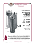
1
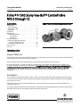
Instruction Manual V150S Slurry Vee-Ball Valve D103164X012 May 2012 Fisherr V150S Slurry Vee-Ball™ Control Valve NPS 3 through 12 Contents Introduction . . . . . . . . . . . . . . . . . . . . . . . . . . . . . . . . . 1 Scope of Manual . . . . . . . . . . . . . . . . . . . . . . . . . . . . . 1 Specification table . . . . . . . . . . . . . . . . . . . . . . . . . . . 2 Description . . . . . . . . . . . . . . . . . . . . . . . . . . . . . . . . . 2 Installation . . . . . . . . . . . . . . . . . . . . . . . . . . . . . . . . . . . . 3 Maintenance . . . . . . . . . . . . . . . . . . . . . . . . . . . . . . . . . . 6 Packing Maintenance . . . . . . . . . . . . . . . . . . . . . . . . 6 Disassembly . . . . . . . . . . . . . . . . . . . . . . . . . . . . 6 Assembly . . . . . . . . . . . . . . . . . . . . . . . . . . . . . . . 8 Actuator Mounting . . . . . . . . . . . . . . . . . . . . . . . . . . . . . 9 Determining Mounting Position for Spline Shaft/Lever Type . . . . . . . . . . . . . . . . . 10 Determining Closed Position . . . . . . . . . . . . . . . . . 10 Parts Ordering . . . . . . . . . . . . . . . . . . . . . . . . . . . . . . . . 13 Parts List . . . . . . . . . . . . . . . . . . . . . . . . . . . . . . . . . . . . . 13 Figure 1. Fisher V150S Slurry Vee-Ball Control Valve W8512 Introduction Scope of Manual This instruction manual provides installation, operation, maintenance, and parts information for Fisher Vee-Ball V150S (NPS 3 through 12) rotary control valves (see figure 1). Refer to separate manuals for information concerning the actuator, positioner and accessories. Do not install, operate, or maintain V150S valves without being fully trained and qualified in valve, actuator, and accessory installation, operation, and maintenance. To avoid personal injury or property damage, it is important to carefully read, understand, and follow all the contents of this manual, including all safety cautions and warnings. If you have any questions about these instructions, contact your Emerson Process Management sales office before proceeding. Description The V150S Slurry Vee-Ball valve shown in figure 1 mates with CL150 raised face flanges. Rugged construction, highly wear-resistant trim materials, and an unrestricted straight through flow path make the design ideal for controlling the most abrasive of slurries. A shaft with a choice of drive connections will allow a variety of power operated actuators and valve positioners or controllers to be used. The design is particularly effective in minimizing erosive damage to the adjoining pipework, thereby providing greater operational safety and service life when compared with other valve types. www.Fisher.com Instruction Manual V150S Slurry Vee-Ball Valve May 2012 D103164X012 Table 1. Specifications Valve Sizes and End Connection Styles NPS J 3, J 4, J 6, J 8, J 10, and J 12 with CL150 raised-face flanges Shutoff Classification Construction does not provide tight shutoff. Nominal gap between ball and flow ring seat is 0.035 inch for high chrome iron construction and 0.015 inch for ceramic insert construction. Construction Materials Standard Construction: See table 2 Flow Direction Reverse flow recommended (into concave face of ball, out through the flow ring) Valve Installation Shaft axis shall be horizontal Actuator Mounting Right-hand or left-hand, as viewed from upstream end of valve Maximum Ball Rotation 90 degrees Valve/Actuator Action With diaphragm or piston rotary actuator and splined shaft, the valve is field-reversible between PDTC or PDTO: J push-down-to-close (extending actuator rod closes valve) and J push-down-to-open (extending actuator rod opens valve) Table 2. Standard Construction Materials 2 Part Material Valve Body Carbon Steel ASTM A216 WCC Body Liner High Chrome Iron ASTM A532 Class III Type A V-notch Ball High Chrome Iron ASTM A532 Class III Type A Flow Ring High Chrome Iron ASTM A532 Class III Type A Flow Ring Insert type (optional) High Chrome Iron ASTM A532 Class III Type A Flow Ring Retainer Carbon Steel ASTM A105 Bearing Shroud High Chrome Iron ASTM A532 Class III Type A Bearing 440C 58Rc Drive Shaft 17-4PH Cond. H1025 Follower Shaft 17-4PH Cond. H1025 Shaft Pins Carbon Steel, zinc plated Spring Carbon Steel Gaskets Graphite SST Laminate. Packing Set PTFE, Carbon Filled Packing Set (optional) Graphite Packing Box Ring and Follower 316 SST Studs SA-193-B7 Nuts SA-194-2H Retainer Screws and Clips 316 SST Flow Ring Insert (optional) PSZ Ceramic V-notch Ball (optional) PSZ ceramic Instruction Manual V150S Slurry Vee-Ball Valve D103164X012 May 2012 Figure 2. Flange Stud Length for Seal Protector End DIMENSION SHOWN IN TABLE 3 FIRST FULL THREAD TO FIRST FULL THREAD 1A4520 Table 3. Flange Stud Lengths Required for Flow Ring End of Fisher V150S Valves V150S VALVE SIZE, NPS mm Inches 3 4 6 8 10 12 95 108 114 183 222 256 3.75 4.25 4.50 7.19 8.72 10.10 Specifications Specifications for these valves are shown in table 1 and in bulletin 51.3:V150S. Installation WARNING Safe work practices should be followed when handling the valve and actuator. Some types of ceramic trim, including PSZ, can create a spark under certain conditions when an edge of one ceramic part is struck against a second ceramic part with enough force. Do not use ceramic trim where the process fluid has volatile or combustible properties. The valve drive shaft is not necessarily grounded to the pipeline when installed. Personal injury or property damage could result from an explosion caused by a discharge of static electricity from valve components if the process fluid or the atmosphere around the valve is flammable. If the valve is installed in a hazardous area, electrically bond the drive shaft to the valve. WARNING Always wear protective gloves, clothing, and eyewear when performing any installation operations to avoid personal injury. Personal injury or equipment damage caused by sudden release of pressure may result if the valve assembly is installed where service conditions could exceed either the valve body rating or the mating pipe flange joint rating. To avoid such injury or damage, provide a relief valve for overpressure protection as required by government or accepted industry codes and good engineering practices. 3 Instruction Manual V150S Slurry Vee-Ball Valve May 2012 D103164X012 Check with your process or safety engineer for any additional measures that must be taken to protect against process media. If installing into an existing application, also refer to the WARNING at the beginning of the Maintenance section in this instruction manual. CAUTION When ordered, the valve configuration and construction materials were selected to meet particular pressure, temperature, pressure drop, and controlled fluid conditions. Responsibility for the safety of process media and compatibility of valve materials with process media rests solely with the purchaser and end-user. Because some valve/trim material combinations are limited in their pressure drop and temperature ranges, do not apply any other conditions to the valve without first contacting your Emerson Process Management sales office. Figure 3. Optional Shaft-to-Body Bonding Strap Assembly VALVE BODY E0880 VIEW A-A ACTUATOR A A 24 1. Install the valve in the direction of the flow arrow fitted to the valve body. 2. Install the valve with the shaft axis in the horizontal position. 3. If required, fit a bonding strap assembly (key 131) to the drive shaft (key 8) with the clamp, (key 130, figure 3) and connect the other end of the bonding strap assembly to the valve body with actuator mounting cap screw. 4. If the valve and actuator have been purchased separately or if the actuator has been removed, mount the actuator according to the Actuator Mounting section and the appropriate actuator instruction manual. 5. The actuator can be right- or left-hand mounted with the shaft in a horizontal orientation as shown in figure 1. If necessary, refer to the appropriate actuator instruction manual for actuator installation and adjustment procedures. 4 Instruction Manual V150S Slurry Vee-Ball Valve D103164X012 May 2012 Table 4. Fisher V150S Dimensions V150S DIMENSIONS(1) VALVE SIZE A B D G K DN M(2) N(2) S Diameter T U W mm 80 165 80.0 235 140 130 104 98.0 19.1 152 31.8 14.2 100 194 102 214 152 140 117 98.0 19.1 152 31.8 14.2 150 230 111 214 175 164 124 112 25.4 152 31.8 14.2 200 304 184 208 220 231 195 124 31.8 235 46.0 17.5 250 385 235 208 250 261 235 132 31.8 235 46.0 17.5 300 455 291 208 300 304 270 132 38.1 235 46.0 17.5 NPS Inch 3 6.49 3.15 9.26 5.51 5.12 4.11 3.86 0.75 6.00 1.25 0.56 4 7.62 4.02 8.44 5.98 5.53 4.61 3.86 0.75 6.00 1.25 0.56 6 9.06 4.38 8.44 6.89 6.45 4.90 4.40 1.00 6.00 1.25 0.56 8 11.96 7.25 8.19 8.66 9.11 7.68 4.90 1.25 9.25 1.81 0.69 10 15.16 9.26 8.18 9.84 10.26 9.25 5.19 1.25 9.25 1.81 0.69 12 17.91 11.47 8.18 11.81 11.97 10.63 5.19 1.50 9.25 1.81 0.69 1. Stud length associated with clearance dimension “M” is longer than standard length specified in ANSI B16.5. 2. Clearance necessary to remove flange bolts. Figure 4. Fisher V150S Dimensions (see table 4) U S DIAMETER T W N M B G NPS 3 THROUGH 12 D A E0875 Table 5. Fisher V150S Dimensions for Double D Shaft Drive VALVE SIZE K E S(1) FLAT LENGTH DN T U Figure 5. Fisher V150S Dimensions for Double D Shaft Drive (see table 5) W E mm 80 83 19.0 25.4 95 25 100 83 19.0 25.4 95 25 150 83 25.4 25.4 95 25 200 83 31.8 25.4 133 38 250 89 31.8 25.4 133 38 300 89 38.1 38.1 133 38 NPS FLAT SIZE FLAT LENGTH S see below T Inch 3 3.25 3/4 1.0 3.75 1.0 1/2-13 4 3.25 3/4 1.0 3.75 1.0 1/2-13 6 3.25 1 1.0 3.75 1.0 1/2-13 8 3.25 1-1/4 1.0 5.25 1.5 5/8-11 10 3.5 1-1/4 1.0 5.25 1.5 5/8-11 12 3.5 1-1/2 1.5 5.25 1.5 5/8-11 W U 38B2695-A 1. This nominal valve shaft diameter is the shaft diameter through the packing box. Use this diameter when selecting Fisher actuators. 5 V150S Slurry Vee-Ball Valve May 2012 Instruction Manual D103164X012 Maintenance WARNING The V-notch ball closes with a shearing, cutting motion, which could result in personal injury. To avoid injury, keep hands, tools, and other objects away from the V-notch ball while stroking the valve. Avoid personal injury from sudden release of process pressure. Before performing any maintenance operations: D Do not remove the actuator from the valve while the valve is still pressurized. D Disconnect any operating lines providing air pressure, electric power, or a control signal to the actuator. Be sure the actuator cannot suddenly open or close the valve. D Use bypass valves or completely shut off the process to isolate the valve from process pressure. Relieve process pressure from both sides of the valve. Drain the process media from both sides of the valve. D Vent the power actuator loading pressure and relieve any actuator spring precompression. D Use lock-out procedures to be sure that the above measures stay in effect while you work on the equipment. D Always wear protective gloves, clothing, and eyewear when performing any maintenance operations to avoid personal injury. D The valve packing area may contain process fluids that are pressurized, even when the valve has been removed from the pipeline. Process fluids may spray out under pressure when removing the packing hardware or packing rings. D Check with your process or safety engineer for any additional measures that must be taken to protect against process media. Packing Maintenance 1. It is recommended that the valve be removed from the line when replacing packing to allow correct set up of the actuator after actuator removal. 2. Remove the packing follower nuts and packing follower (keys 18 and 16). 3. Remove the packing parts (see figure 4 and keys 15 and 14) using a purposed designed packing extraction tool to avoid damaging the packing box bore and shaft surfaces. 4. Install the new packing parts using the sequence shown in figure 4. Fit the packing follower (key 16). Fit nuts (key 18). 5. Tighten the packing nuts to compress the packing to seal for operating conditions. At the same time push the ball and shroud on the drive end against the valve body inside location face to center the ball. This can be done by using a lever (wood) against the inside ball lug face and the valve body liner inlet. Disassembly WARNING Observe the steps in the WARNING at the beginning of the Maintenance section. Reference figures 9 and 10. 6 Instruction Manual V150S Slurry Vee-Ball Valve D103164X012 May 2012 Figure 6. Packing Arrangements PACKING FOLLOWER (KEY 16) PACKING FOLLOWER (KEY 16) PACKING SET (KEY 15) PACKING SET (KEY 15) 1 PACKING BOX RING (KEY 14) PTFE V-RING PACKING FOR V150S NOTE: INCLUDES ZINC WASHERS FOR 1 GRAPHITE RIBBON PACKING ONLY. PACKING BOX RING (KEY 14) GRAPHITE RIBBON PACKING FOR V150S STANDARD PACKING 28B5170 CAUTION Trim parts are made from brittle material, handle with care to avoid chipping or breakage. 1. Remove the actuator cover (where applicable). Take note of the orientation of the actuator with respect to the valve body and the lever orientation with respect to the valve drive shaft. 2. Remove the actuator. 3. Remove the flow ring retainer screws, clips and flow ring retainer (keys 22, 23, and 5). 4. Knock or press out the flow ring (key 4). 5. Position the ball to allow access to the shaft pins. Use a modified parallel pin punch (figure 7) to to knock out the shaft pins, (key 10) through the shaft and ball lugs. Note The punch dimensions should be as per table 6 to avoid damaging the ball and shaft. The hole diameter in the ball is larger than the hole in the shaft and the punch needs to be centrally located with the pin. 6. Remove packing follower (key 16). Remove plug (key 20) and spring, (key 19). 7. Knock or press each shaft (key 9) out through the ball and the bearings (key 7). 8. Remove ball (key 3) and shrouds (key 6). 9. Knock, press or pull out bearings (key 7). 10. Knock or press out body liner (key 2). 11. Remove packing (key 15). 7 V150S Slurry Vee-Ball Valve Instruction Manual May 2012 D103164X012 For service applications involving scale formation that sets up and “freezes” mating parts, supplementary recommendations for disassembly can be provided by your Emerson Process Management sales office. Assembly WARNING Observe the steps in the WARNING at the beginning of the Maintenance section. Reference figures 9 and 10. CAUTION Trim parts are made from brittle material, handle with care to avoid chipping or breakage. 1. Clean all surfaces of the parts to be used. Ensure all mating surfaces are in good condition and free from scratches and dents. Replace worn parts. Fit new gaskets (key 13 and 21) and packing (key 15). 2. Position the valve body with flow arrow uppermost. 3. Fit the valve body liner (key 2) into the valve body, aligning cross-holes with shaft bore axis. 4. Fit the bearings (key 7) through the valve body liner into the valve body. 5. Place bearing shrouds (key 6) over the bearings and through the valve body liner to contact faces in the valve body bore. 6. Orientate the ball (key 3) so that the lug with the location slot will be on the non-drive side of the valve body, that is opposite from the actuator. Place the ball on a wad of rag to rest in the bottom of the valve body with the lugs uppermost. Fit the drive shaft (key 8) through the bearing on the drive side and into the hexagon hole of the ball, aligning the holes for the shaft pins. With a splined shaft, the indicator line on the splined shaft end should be on the ball side to indicate the ball “seat location”. Fit the follower shaft (key 9). 7. Fit the shaft pins (key 10) through the ball and into the shaft using a pin punch (figure 7). Position the pins approximately centrally about the shaft axis. 8. Next install the packing. Fit the studs (key 17 ), packing box ring (key 14), packing set (key 15), packing follower (key 16), and nuts (key 18). Adjust the packing tightness for use. 9. Before fitting the flow ring, tap the end of the bearing on the drive end to ensure that the ball/shroud assembly is hard against the valve body inner recess location on the drive end. 10. Next fit the flow ring. a. For one piece High Chrome Iron flow ring (key 4), fit into the valve body and valve body liner. Fit the gasket, (key 13) and flow ring retainer (key 5). Secure with retainer screws (key 22) and clips (key 23). Check that the ball rotates freely. b. For flow ring with ceramic insert, position the valve body on the valve body liner flange face with the ball secured and facing upwards. Make sure the flow ring insert type (key 28) and flow ring insert (key 29) are clean and free of grease and oil. Apply a bead of Loctitet 620 around the smaller outside diameter of the ceramic insert and push the insert into the flow ring. Place shims on the upper ball face (recommended thickness 0.015 inch) and lower the flow ring assembly into place. Secure with retainer, screws and clips. Push the insert down onto the shims and allow the adhesive to set. 8 Instruction Manual V150S Slurry Vee-Ball Valve D103164X012 May 2012 11. Fit the spring (key 19), gasket (key 21), and plug (key 20). For service applications involving scale formation that sets up and “freezes” mating parts, supplementary recommendations for assembly can be provided by your Emerson Process Management sales office. Actuator Mounting Use the appropriate actuator instruction manual, this section of this manual, and figure 8 of this manual when mounting the actuator or changing actuator styles and positions. 1. To help ensure correct centering of the V-notch ball (key 3) on the flow ring (key 4 or 28/29), be sure the ball is closed when mounting the actuator (for applications other than Spring Return Fail-Open). Figure 7. Pin Punch D C 0.010 R 0.010 MAX B A E0878 Table 6. Pin Punch Dimensions Valve Size, NPS Ball Pin Hole Shaft Pin Hole A Min B Max C Max D Min 3 and 4 0.19 0.16 0.25 0.15 0.085 1.45 6 0.22 0.19 0.25 0.18 0.105 1.85 8 and 10 0.28 0.25 0.38 0.24 0.135 2.2 12 0.28 0.25 0.38 0.24 0.135 2.6 2. Clean the valve shaft and actuator lever splines to be sure the actuator lever will slide on easily. Only drive the lever in if absolutely necessary. 3. Carefully wedge the ball solidly against the actuator-side bearing to center the ball. 4. Keep the wedge in place while installing the lever, if necessary. Remove the wedge after you have clamped the actuator lever on the valve shaft and have connected the lever to the actuator piston rod or diaphragm rod. Determining Mounting Position for Spline Shaft/Lever Type The actuator can be either right or left-hand mounted, with the actuator on the right or left side when viewed from upstream (see figure 8). For right-hand mounting (standard), the ball will be in the top of the valve body when the valve is open and the shaft is horizontal. In this position the ball rotates CW to Close. For left-hand mounting, the ball will be in the top of the valve body when the valve is open and the shaft is horizontal. In this position the ball rotates CCW to Close. 9 Instruction Manual V150S Slurry Vee-Ball Valve May 2012 D103164X012 Figure 8. Index Marks for Actuator Lever Orientation for NPS 3 through 12 Valves ACTUATOR MOUNTING STYLE VALVE OPEN ACTUATOR POSITION 1 2 3 4 STYLE D PUSH DOWN TO CLOSE (OPTIONAL) LEFT-HAND BALL ROTATES COUNTERCLOCKWISE TO CLOSE FLOW STYLE C PUSH DOWN TO OPEN FLOW STYLE B PUSH DOWN TO CLOSE (STANDARD) RIGHT-HAND BALL ROTATES CLOCKWISE TO CLOSE FLOW STYLE A PUSH DOWN TO OPEN FLOW NOTE: 1. ARROW ON LEVER INDICATES DIRECTION OF ACTUATOR THRUST TO CLOSE VALVE. E0881-1 Determining Closed Position 1. The valve must be removed from the line to check the position of the ball. WARNING The V-notch ball closes with a shearing, cutting motion. To avoid personal injury, keep hands, tools, and other objects away from the ball while stroking the valve. 2. Rotate the ball to the closed position. 3. Position the ball in the proper location. 4. The ball is in its closed position when the Vee plane of the ball, (opposite the convex side) is parallel to the liner end flange face of the valve body. Measure to check. Adjust the actuator linkage or travel stops to position. CAUTION To extend operating life of the V-notch ball, always ensure the V-notch ball rotates into the top of the valve body to open. 10 Instruction Manual V150S Slurry Vee-Ball Valve D103164X012 May 2012 Figure 9. Exploded View, Fisher V150S NPS 3 through 12 (Including Alternative Ceramic Insert Construction, Keys 28 and 29) 2 20 29 1 19 9 28 7 21 10 14 15 17 18 23 24 3 22 8 6 16 4 13 5 W8513 11 V150S Slurry Vee-Ball Valve May 2012 Figure 10. Fisher V150S Assembly E0879 12 Instruction Manual D103164X012 Instruction Manual V150S Slurry Vee-Ball Valve D103164X012 May 2012 Parts Ordering A serial number is assigned to each valve and stamped on the nameplate. Always refer to the valve serial number when corresponding with your Emerson Process Management sales office regarding spare parts or technical information. When ordering replacement parts, also specify the complete 11-character part number from the parts kits or parts list information. WARNING Use only genuine Fisher replacement parts. Components that are not supplied by Emerson Process Management should not, under any circumstances, be used in any Fisher valve, because they may void your warranty, might adversely affect the performance of the valve, and could cause personal injury and property damage. Parts List Key Note Part numbers are shown for recommended spares only. For other part numbers, contact your Emerson Process Management sales office. 4* Common Parts (figures 9 and 10) Key 1 2* 3* Description Part Number If you need a valve body as a replacement part, order by valve size, serial number, and desired valve body material. Contact your Emerson Process Management sales office for assistance. Valve Body Liner, High Chrome Iron Schedule 40 NPS 3 1B12124U012 NPS 4 1B12125U012 NPS 6 2B12083U012 NPS 8 2B12193U012 NPS 10 2B12194U012 NPS 12 3B12220U012 Schedule 80 NPS 3 2B12127U012 NPS 4 2B12156U012 NPS 6 2B12021U012 NPS 8 2B12196U012 NPS 10 2B12197U012 NPS 12 3B12219U012 V-notch Ball Standard, High Chrome Iron NPS 3 3B12121U012 NPS 4 3B12077U012 NPS 6 3B12017U012 NPS 8 3B12079U012 NPS 10 3B12192U012 *Recommended spare parts 5 6* 7* Description NPS 12 PSZ Ceramic NPS 3 NPS 4 NPS 6 NPS 8 NPS 10 NPS 12 Flow Ring, High Chrome Iron Schedule 40 NPS 3 NPS 4 NPS 6 NPS 8 NPS 10 NPS 12 Schedule 80 NPS 3 NPS 4 NPS 6 NPS 8 NPS 10 NPS 12 Flow Ring Retainer Bearing Shroud, High Chrome Iron (2 req'd) NPS 3 NPS 4 NPS 6 NPS 8 NPS 10 NPS 12 Bearing, 440C (2 req'd) NPS 3 NPS 4 NPS 6 NPS 8 NPS 10 NPS 12 Part Number 3B12222U012 3B12276U012 3B12277U012 3B12278U012 3B12279U012 3B12280U012 3B12281U012 1B12086U012 1B12110U012 2B12082U012 2B12183U012 2B12185U012 3B12213U012 1B12085U012 1B12111U012 2B12019U012 2B12184U012 2B12186U012 3B12215U012 1B12100U012 1B12100U012 1B12062U012 1B12170U012 1B12170U012 1B12201U012 1B12119U012 1B12119U012 1B12031U012 1B12191U012 1B12191U012 1B12217U012 13 Instruction Manual V150S Slurry Vee-Ball Valve May 2012 Key 8 8 9 10* 13* 14* 15* 16 17 18 14 Description Drive Shaft Spline Drive Shaft, DD Follower Shaft Shaft Pin, carbon steel, zinc plated (2 req'd) NPS 3 NPS 4 NPS 6 NPS 8 NPS 10 NPS 12 Gasket, graphite/laminate NPS 3 NPS 4 NPS 6 NPS 8 NPS 10 NPS 12 Packing Box Ring, 316 SST NPS 3 and 4 NPS 6 NPS 8 NPS 10 NPS 12 Packing Set PTFE NPS 3 and 4 NPS 6 NPS 8 NPS 10 NPS 12 Graphite/laminate NPS 3 and 4 NPS 6 NPS 8 NPS 10 NPS 12 Packing Follower Stud, 2 req'd Nut, 2 req'd D103164X012 Part Number Key Description 19 20 21* 1B12096U012 1B12096U012 1B12034U012 1B12166U012 1B12166U012 1B12206U012 1B12133U012 1B12108U012 1B12036U012 1B12162U012 1B12177U012 1B12203U012 22 23 24 25 26 27 28 16A6084X012 16A6085X012 16A6086X012 16A6086X012 16A6087X012 12A8995X022 12A8832X022 12A8951X022 12A8951X022 12A8935X022 29 12A9136X012 12A9137X012 12A9138X012 12A9138X012 12A9139X012 130 131 Spring Plug Gasket, graphite/laminate NPS 3 and 4 NPS 6 NPS 8 NPS 10 NPS 12 Retainer Screw, 2 req'd Retainer Clip, 2 req'd Actuator Mounting Screw, 4 req'd Nameplate Drive Screw, 4 req'd Flow Arrow Flow Ring Insert type, High Chrome Iron Schedule 40 NPS 3 NPS 4 NPS 6 NPS 8 NPS 10 NPS 12 Schedule 80 NPS 3 NPS 4 NPS 6 NPS 8 NPS 10 NPS 12 Flow Ring Insert PSZ Ceramic NPS 3 NPS 4 NPS 6 NPS 8 NPS 10 NPS 12 Clamp Bearing Clamp Assembly *Recommended spare parts Part Number 1B12098U012 1B12044U012 1B12168U012 1B12168U012 1B12204U012 1B12088U012 1B12112U012 2B12084U012 2B12181U012 2B12187U012 3B12214U012 1B12087U012 1B12113U012 2B12050U012 2B12182U012 2B12188U012 3B12216U012 1B12134U012 1B12109U012 2B12046U012 2B12157U012 2B12172U012 2B12210U012 Instruction Manual D103164X012 V150S Slurry Vee-Ball Valve May 2012 15 V150S Slurry Vee-Ball Valve May 2012 Instruction Manual D103164X012 Neither Emerson, Emerson Process Management, nor any of their affiliated entities assumes responsibility for the selection, use or maintenance of any product. Responsibility for proper selection, use, and maintenance of any product remains solely with the purchaser and end user. Fisher and Vee-Ball are marks owned by one of the companies in the Emerson Process Management business unit of Emerson Electric Co. Emerson Process Management, Emerson, and the Emerson logo are trademarks and service marks of Emerson Electric Co. All other marks are the property of their respective owners. The contents of this publication are presented for informational purposes only, and while every effort has been made to ensure their accuracy, they are not to be construed as warranties or guarantees, express or implied, regarding the products or services described herein or their use or applicability. All sales are governed by our terms and conditions, which are available upon request. We reserve the right to modify or improve the designs or specifications of such products at any time without notice. Emerson Process Management Marshalltown, Iowa 50158 USA Sorocaba, 18087 Brazil Chatham, Kent ME4 4QZ UK Dubai, United Arab Emirates Singapore 128461 Singapore www.Fisher.com 16 E 2003, 2012 Fisher Controls International LLC. All rights reserved.