1
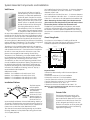
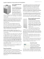
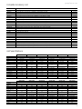
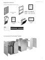
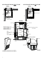
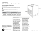
GE Zoneline vertical
packaged terminal
air conditioners
®
2010 Architects and Engineers Data Manual
Specifications
230/208 Volt Models
Features
Electric resistance heat
Heat pumps
Cool only
AZ85E09DAC AZ85E12DAC AZ85E18DAC AZ85H09DAC AZ85H12DAC AZ85H18DAC AZ85W09DAC AZ85W12DAC AZ85W18DAC
BTUH
9,000/8,800 11,700/11,500 17,900/17,700 8,800/8,600 11,700/11,500 17,800/17,700
E.E.R. (BTUH/Watt)
10.5/10.5
10.6/10.6
9.3/9.3
10.5/10.5
10.6/10.6
9.3/9.3
Dehumidification (pints/hr.)
2.5
3.2
5.0
2.5
3.2
5.0
Universal Heater (kW
@ 230 volts)
2.61/3.42/4.81 2.61/3.42/4.81 2.61/3.42/4.81 2.61/3.42/4.81 2.61/3.42/4.81 2.61/3.42/4.81
Reverse cycle (BTUH)
N/A
N/A
N/A
8,200/8,000 10,400/10,300 16,400/16,200
COP @ 47°
N/A
N/A
N/A
3.4
3.4
3.0
SHR
0.81
0.79
0.71
0.83
0.79
0.69
Indoor CFM (Hi/Med/Low)
0.0" ESP
520/460/360 590/500/380 600/520/400 520/460/360 590/500/380 600/520/400
Electric resistance heat
265 Volt Models
9,000/8,800
10.5/10.5
2.5
11,700/11,500 17,900/17,700
10.6/10.6
9.3/9.3
3.2
5.0
N/A
N/A
N/A
0.81
N/A
N/A
N/A
0.79
N/A
N/A
N/A
0.71
520/460/360
590/500/380
600/520/400
Heat pumps
AZ85E09EAC AZ85E12EAC AZ85E18EAC AZ85H09EAC AZ85H12EAC AZ85H18EAC
Features
BTUH
9,000
11,700
17,900
8,800
11,700
17,800
E.E.R.
10.5
10.6
9.3
10.5
10.6
9.3
Dehumidification (pints/hr.)
2.5
3.2
5.0
2.5
3.2
5.0
Universal Heater (kW)
2.71/3.55/5.03 2.71/3.55/5.03 2.71/3.55/5.03 2.71/3.55/5.03 2.71/3.55/5.03 2.71/3.55/5.03
Reverse Cycle (BTUH)
N/A
N/A
N/A
8,200
10,400
16,400
COP @ 47°
N/A
N/A
N/A
3.4
3.4
3.0
SHR
0.82
0.80
0.70
0.83
0.79
0.70
Indoor CFM (Hi/Med/Low)
0.0" ESP
520/460/360 590/500/380 600/520/400 520/460/360 590/500/380 600/520/400
265 Volt available by special order.
Zoneline® Vertical Unit Nomenclature
The Zoneline vertical unit is identified by a model number defining the type of unit, cooling capacity, and electrical information.
When specifying or ordering the Zoneline Vertical unit the use of this nomenclature will assure receiving the correct unit. EXAMPLE
A
Z
Zoneline®
packaged
terminal unit
8
Chassis series
85=vertical
Unit type
E=cooling with electric
resistance heat
H=heat pump with electric
resistance heat
W=Cool only
5
E
0
Nominal cooling capacity
09=8,800 BTUH cooling
12=11,700 BTUH cooling
18=17,900 BTUH cooling
2
D
A
C
Heater
configuration
A=Universal heater
See power
connection kits
section
Voltage/Phase/Frequency
Special Features
D=230/208 Volt, single phase, 60 Hz C=corrosion protection
E=265 Volt, single phase, 60 Hz
Other components are necessary for a complete
installation - see System Essential Components section.
Listed by
Underwriters'
Laboratories.
9
geappliances.com
Table of Contents
Front Cover.................................................................................................................. 1
Mini-Specs/Nomenclature....................................................................... 2
Table of Contents......................................................................................... 3
Introduction..................................................................................................... 4
GE Zoneline® Vertical Packaged Terminal Unit.............................. 5
Features and Benefits............................................................................6-9
System Essential Components.................................................... 10-12
Accessory List/Unit Specifications.................................................... 13
Air Flow Table/Dip Switches/Terminal Block - Line Art........... 14
Required Accessories Line Art/Expanded View.......................... 15
Utility Closet and Dimensions.............................................................. 16
Suggested Bid Form Specifications.................................................. 17
Additional Specifications....................................................................... 18
Warranty....................................................................................................... 19
Important Notice
Equipment used as a primary source for
heating or cooling is an integral part of
the building in which it is installed. Proper
application is essential for satisfactory
performance over a wide range of
operating conditions. It is strongly
recommended that a professional
engineer determine proper application.
If this unit is a replacement unit,
its specifications and performance
may differ from those of the unit it is
replacing. For that reason, we again
strongly recommend that a professional
engineer determine proper application.
3
Introduction
Today, guests in lodging properties, assisted living facilities and apartments desire rooms with a more home-like appearance.
They expect the comforts they are accustomed to, whether they spend one night or many years. Toward that end, many lodging
properties provide refrigerators, microwave ovens and remote control televisions. Many assisted living facilities provide full-size
kitchen appliances in each individual apartment. All of these improvements are an attempt to improve the comfort
and satisfaction of the occupant by providing a more home-like environment.
Upgrading the air conditioning and heating provides another opportunity to enhance guest comfort. Years ago, an acceptable
means of creating a comfortable environment was to install a window air conditioner and an electric heater mounted on the
wall. The GE Zoneline® was the first packaged terminal air conditioner introduced to the market, and it led the way in improving
comfort and efficiency. And they are still used extensively as an alternative to large, expensive central systems.
However, there are some inherent issues with packaged terminal units. First, since all of the components are contained in the
chassis, the compressor and fan sounds can be heard in the room. In addition, since the units are usually mounted under the
window there are limitations to furniture placement and curtains cannot hang to the floor. Finally, some people find the controls
difficult to adjust for the desired temperature.
The Vertical Packaged Terminal Air Conditioner
To address these issues, GE introduced the Vertical Zoneline. It
is still a through-the-wall, packaged terminal unit, but instead
of being 42" wide and installed in the middle of the room, it has
a vertical configuration and is installed in a closet-like corner
enclosure. The GE Zoneline Vertical Packaged Terminal Air
Conditioner (ZVAC) is approximately 24" x 24" and has a top air
discharge that is ducted into a single room or multiple rooms.
It is controlled by a wall-mounted thermostat similar to those
found in most homes.
Because the new ZVAC is installed in a closet, it provides
a more home-like appearance to the room as well as quieter
operation. And guests prefer the wall thermostat because
it provides more precise settings. Since the vertical Zoneline
is not installed under a window in the middle of the room,
curtains can hang all the way to the floor, and more versatile
room designs are possible. Because the unit is ducted, it can
serve a single room or multiple rooms.
The GE Zoneline Vertical Packaged Terminal Air Conditioner
is a great option to standard PTACs for cooling and heating
a variety of rooms. It provides the costs benefit of packaged
terminal units with the aesthetics, quieter operation and
flexibility of a central system.
4
The GE Zoneline Vertical Packaged Terminal Air Conditioner
®
geappliances.com
The GE Zoneline® vertical air conditioner is available in 8,800 BTUH, 11,700 BTUH or 17,800 BTUH cooling capacity with either
resistance heat, cool only or heat pump units with resistance heat backup. Each cooling capacity is available in a dual rated
unit that operates on either 230 volts or 208 volts and in a unit designed to operate on 265 (277) volts. All units, except cool only
models are equipped with a 3-element universal heater that provides electric heat backup when connected with the appropriate
9-pin power connection kit to 208-volt, 230-volt or 265(277) volt power. See page 12 for information on the power connection kits.
System Features
System Essential Components
The ZVAC has a number of features that help distinguish
it as the leader in the vertical unit industry. Each feature is
discussed in detail in the Features and Benefits section.
• Excellent efficiency and dehumidification
• Unique sleeve design for easier installation and service
• Three-way slide-out chassis service/maintenance flexibility
• Electronic Temperature Limiting (requires room air
temperature sensor accessory - RAVRMS)
• Freeze Sentinel™ (requires room air temperature sensor
accessory - RAVRMS)
• Constant ON fan (required in nursing homes in some states)
• Permanently Lubricated Fan Motors
• Standard Size Air Filter (20 x 20 x 1)
• Central Desk Control Capability
• Occupancy Sensor Interface
• HI and LOW fan speeds controlled by remote thermostat
• 3-Speed Indoor Fan Motor for selectable HI and LOW speeds
• Corrosion Protection Treatment Standard
• Slinger Ring Condensate Removal
• Indoor Frost Control
• Automatic Compressor Random Restart
• Compressor Restart Delay
• Quick Heat Recovery (On Heat Pump Units)
• Extended Heat Pump Operation
• Reverse Cycle Heat Pump Defrost
• Warranty (including both parts and labor)
• Installation Platform (field supplied)
• Wall Plenum
• Exterior Grille
• Chassis
• Case
• Power Connection Kit
• Remote Thermostat
• Filter (field supplied)
• Return Air Grille
• Ductwork (field supplied)
• Supply Register (field supplied)
5
Features and Benefits
Excellent efficiency and dehumidification
Cooling Temperature Limits degrees F.
GE recognizes the importance of energy efficiency and
dehumidification in an air conditioning system and uses
EER (Energy Efficiency Rating) as a means of reporting the
relative cooling efficiency of the unit.
EER is the rating system used for Packaged Terminal Air
Conditioners and Heat Pumps.
The GE Zoneline® Vertical Packaged Terminal Heat Pump has
outstanding COP ratings. The measurement of the efficiency
of the heat pump output, when compared to electric resistance
heat, is called the Coefficient of Performance (COP). This
number provides a basis not only for comparing the heat
pump output to electric resistance heat, but also the ability
to directly compare heat pumps with the same range of
capacity to one another.
Min
Max
Unique Sleeve Design
The ZVAC case is installed on a field supplied platform and
attached to the wall plenum with field supplied screws. See
pages 10 and 16 for platform construction details.
The chassis slides into the sleeve, allowing for easy removal
of the unit for servicing and cleaning without the need to
remove condensate lines.
Three-Way Slide-Out Chassis
The case is designed to allow the installation of the chassis
from the front or either side of the case. This provides greater
flexibility in building and room design and unit placement. If
access to the front of the unit is restricted by a wall or furniture
placement, the chassis can slide in from either side of the case.
If an alcove or offset is designed into the building facade,
the three-way slide-out chassis enables the unit to be easily
installed and removed for service.
Electronic Temperature Limiting
Although the vertical unit is controlled by a wall mounted
thermostat, there may be a need to prevent the temperature
from being set to extreme energy wasting settings. The ZVAC
unit has seven independent programmable heating and
cooling temperature limits. A wide selection of limits eliminates
the need to reset the limits seasonally. The Temperature
Limiting feature requires the use of the optional room
air temperature sensor, model RAVRMS. Designed to be
mounted on the wall of the unit enclosure closet, the Room Air
Temperature Sensor allows any compatible thermostat to be
used with the unit and provide Temperature Limiting.
The limits are set by dip switches located on the ZVAC unit and
are not accessible by the room occupant. Location of the dip
switches and the temperature settings are shown on page 14.
6
60°
85°
64°
85°
66°
85°
68°
85°
70°
85°
72°
85°
74°
85°
76°
85°
60°
70°
60°
65°
Heating Temperature Limits degrees F.
Min
Max
60°
85°
60°
80°
60°
78°
60°
76°
60°
74°
60°
72°
Freeze Sentinel™
To prevent damage to plumbing and room furnishings by
freezing temperatures, the ZVAC unit can provide Freeze
Sentinel which turns the resistance heaters on at 41° F.,
warms the indoor air to 46° F., and shuts the heater off.
The Freeze Sentinel feature requires the use of the
optional Room Air Temperature Sensor, model RAVRMS.
Designed to be mounted on the room side wall of the unit
enclosure closet, the Room Air Temperature Sensor allows any
compatible thermostat to be used with the unit and
provide Freeze Sentinel protection. The Freeze Sentinel
protection is automatic with the installation of the RAVRMS.
Even if the unit is connected to a Central Desk Control system
or a Room Occupancy Sensor system, and the unit is turned
off by the controlling system, Freeze Sentinel is still active to
provide protection. It may be defeated by switching the unit’s
ON/OFF switch to the OFF position, removing the power supply
to the unit or putting #2 dip switch in DOWN position.
Constant ON fan
Some localities may require the indoor fan on Packaged
Terminal Air Conditioners to operate at all times, even when
the wall primary control would normally turn the unit off. To
accommodate this requirement and provide the feature for
use by anyone wanting to operate the unit in this manner,
GE has provided a switch on the ZVAC that will allow this
mode of fan operation.
If the controlling dip switch (#3) is set in the UP setting, the fan
will run unless the unit’s ON/OFF switch is set to the OFF
position or power is removed from the unit.
geappliances.com
Features and Benefits
Permanently Lubricated Fan Motors
Central Desk Control
The ZVAC has two permanently lubricated, totally enclosed
fan motors. The motors are permanently lubricated to reduce
maintenance and totally enclosed to keep dirt and water out
of the motor windings.
Terminals are provided on the unit to allow a Central Desk
Control system to be interfaced with the unit. The most common
installation of this type of system is a switch mounted at the
registration desk; and, upon guest check-in, a switch is activated
to allow the air conditioner to operate.
Likewise, when the guest checks out, the device is switched
to the “OFF” setting so the unit will not operate when the room
is not rented. In some resort areas, devices are connected to
sliding glass doors, and opening the doors causes a contact to
close, turning the air conditioner off. This prevents the unit from
running and wasting energy with the sliding glass open.
Standard Size Air Filter
A number of filters, providing varying degrees of filtering
efficiency are available on the market today. GE has designed
the ZVAC to accommodate a number of filter placement
options. All of the options designed for the unit use a standard
size 20" x 20" x 1" filter. Since the filter is field supplied, GE has
allowed the owner or property manager to decide which type
of filter to use with the unit.
A different size filter may also be used in a field supplied frame
installed in a return air grille mounted in the closet enclosure
door or wall. If a different size filter is used, it must be at least
20" x 20" x 1" and provide no more restriction to air flow than
the standard 20" x 20" x 1" filter.
The unit must not be operated without a filter in place,
even during construction.
GE provides three filter placement options for design and
installation flexibility. A filter bracket is provided in the front
panel of the ZVAC case, which allows the use of a louvered
closet door. The bracket is mounted to allow the filter to be
inserted from the top of the bracket rather than sliding in
from the side, where the enclosure wall may interfere with
filter removal.
An access panel, accessory model number RAVRG1, for the
closet enclosure is the second filter placement option. The
access panel requires a 28" wide by 48" high cutout in the
unit closet enclosure wall and provides access to the unit for
servicing and removal. The access panel should be located in
the wall such that the centerline of the access panel matches
the centerline of the case to allow for removal of the chassis. The
bottom of the access panel should be at least 1" below the unit
support platform to allow for easy removal of the ZVAC unit.
The third filter placement option provided by GE is incorporated
in a return air grille, accessory model number RAVRG2,
designed to be mounted in a flat closet access door. The
door must have a minimum clear opening of 24" to allow for
installation and removal of the unit. GE recommends a 28"
wide door. A 20 3/8" wide by 20 3/8" high cutout is required in
the door to accommodate the grille and filter bracket.
Only one filter is to be used in the installation. Multiple filters
will reduce the air flow and affect unit performance. A clean
filter is essential to efficient unit operation. The filter should
be checked at least every 30 days and replaced if dirty.
Important CDC Notes:
1)The unit requires the use of a normally open switch.
Closing the circuit interrupts power to the unit.
2)Both wires comprising the circuit must connect to the
CDC terminals on the unit and to the controlling switch.
Do not use a common buss (at the unit or at the switch
panel) in the wiring.
3)A 24-volt transformer is contained within the ZVAC unit.
No external voltage may be applied to the unit through
the CDC terminals.
4)Minimum wire size for CDC wiring:
Wire Size # AWG Maximum Allowable Length
#22
600 Ft.
#20
900 Ft.
#18
1500 Ft.
#16
2000 Ft.
Occupancy Sensor Interface
The ZVAC is equipped with a terminal connection to allow it
to interface with a motion sensor and a door sensor to allow
a room occupancy detection system to be connected to the
unit. Various companies market and install room occupancy
systems as a means of reducing the operating cost of
the unit. GE does not market or install these systems but
provides the interface terminals on the unit and logic within
the microprocessor controls to permit these systems to be
installed at a minimum cost to the property owner.
HIGH and LOW Fan Speeds
If the ZVAC is connected to a wall thermostat without the ability
to provide two fan speeds, the fan speed will be determined by
connecting the wire controlling the fan to either the Low Speed
Fan terminal or the High Speed Fan terminal on the unit.
7
Features and Benefits
3-Speed Indoor Fan Motor
for selectable HIGH and LOW speeds
Since the ZVAC discharge air may be routed through duct
work for air distribution into the room and into other rooms,
the units are equipped with a 3-speed fan to provide greater
air movement, to compensate for the additional duct length.
GE recommends an HVAC engineer be consulted to determine
the best fan speed for the application.
A switch on the unit (dip switch #5-duct) adjusts the two-speed
fan system to different settings. With the switch in the UP
position, the system will operate using high and medium fan
speeds. With the switch in the DOWN position, the system will
operate using the medium and low fan speeds.
For example, on the 9,000 BTUH unit, the three fan speeds at
0.2" ESP provide 220 CFM on the lowest fan speed, 370 CFM on
the medium fan speed, and 480 CFM on the highest fan speed.
With the switch down, the unit would provide 220 CFM on
LOW speed and 370 CFM on HIGH speed. With the switch up,
the unit would provide 370 CFM on LOW speed and 480 CFM
on HIGH speed.
Higher CFMs tend to increase the operating sound level, both
from fan noise and from the air noise in the duct. Higher CFMs
also reduce the dehumidification rate of the unit, while lower
CFMs provide quieter operation and better dehumidification.
However, if the CFMs are not high enough to adequately move
the air through the duct system, the unit will not be able to
provide a comfortable room.
Corrosion Protection Treatment (Standard)
All ZVAC units are protected
against damage from seacoast
area corrosion. Components
that are in contact with the
salt air have special coatings
or are made of non-corroding
materials to help withstand
the corrosive effects of the
environment. This protection
includes the use of totally
enclosed fan motors with
painted casings, a special
coating on the outdoor coil, use of stainless steel screws and
brackets, and additional paint on components like the base pan.
Slinger Ring Condensate Removal
Condensate water removed from the indoor air is dispersed
into the air stream by the outdoor fan slinger ring and
deposited on the hot outdoor coil. The water helps cool the
refrigerant in the outdoor coil and increases the efficiency of
the air conditioner.
Indoor Coil Frost Control
Under certain operating conditions, frost can form on the indoor
coil of an air conditioner, reducing air flow, and causing a lack
of cooling complaint. In order to prevent frost from forming, the
ZVAC has an automatic frost control on the indoor coil. When
frost begins to form on the coil, the compressor stops until the
coil temperature increases and the frost dissipates.
At this time, the compressor resumes operation and cooling
continues. The indoor fan remains running during the time
the compressor is off to help warm the coil with room
temperature air.
Automatic Compressor Random Restart
In the event of a power interruption, all compressors
attempting to restart immediately when power is restored
can result in a power surge that can cause another power
failure. The microprocessor in the ZVAC unit has a random
restart logic system that prevents all compressors from
restarting at the same instant.
Compressor Restart Delay
ZVAC units are designed to provide a minimum of three
minutes of compressor off time to allow refrigerant pressures
to equalize before attempting to restart. Attempting to restart
against a high head pressure shortens compressor and
overload protector life.
The units are also designed to provide a minimum of three
minutes of compressor run time to prevent short cycling from
disturbing the room occupant.
Quick Heat Recovery (On Heat Pump Units)
Heat pumps save money compared to electric resistance
heat, but if the unit cannot provide room occupant comfort,
the savings may be of questionable benefit. GE has years of
experience with designing Zoneline heat pumps to solve the
problem of guest complaints.
The heat pump unit incorporates a two-stage heat/one-stage
cooling thermostat that utilizes the resistance heat to bring the
room temperature to within 2°F. of the thermostat set point
before initiating heat pump operation. This method addresses
the two major complaints about heat pump operation: taking
too long to warm the room and low discharge air temperature.
Full electric resistance heat is utilized when the unit is first
turned on or when the unit is operating in heat pump mode
and the temperature in the room falls more than 2°F. below
the thermostat set point.
Extended Heat Pump
Operation/Reverse Cycle Defrost
Heat exists in the outdoor air at temperatures even below 0°F.
Many central systems, with larger outdoor coils, operate in the
heat pump mode down to temperatures in the mid-teens or
even to single-digit temperatures. Central systems are able
8
geappliances.com
Features and Benefits
to operate this low because of the larger outdoor coil area
and because central system heat pumps have a reverse cycle
defrost mode that melts accumulated frost off the outdoor coil.
Other vertical packaged terminal heat pump units terminate
heat pump operation and switch to more expensive resistance
heat at outdoor temperatures in the 40°F. to 45°F. range. They
must terminate heat pump operation before a frost build-up
occurs on the outdoor coil since they have no way of eliminating
the frost.
Ventilation CFM at various ESP points:
GE offers a reverse cycle defrost system, like the central systems,
on all Zoneline Packaged Terminal Heat Pumps. This provides the
owners with the savings realized by the ability to operate in heat
pump mode to lower outdoor temperatures. GE has adapted the
reverse cycle heat pump defrost system to the ZVAC for greater
savings in heat pump mode.
The ZVAC will provide heat pump savings down to a 25°F.
outdoor temperature. At temperatures below 25°F., the unit
will automatically switch to electric heat. When the outdoor
temperature rises to 32°F., the unit will automatically switch
back to heat pump operation. As long as the heat pump output
is able to maintain the room temperature within 2°F. of the
thermostat set point, the unit will run in heat pump mode down
to 25°F. outdoor air temperature. The resistance heater and the
heat pump do not operate simultaneously.
If the outdoor temperature is above 25°F. and if the room
temperature falls more than 2°F. below the set point, the
thermostat automatically switches the unit to resistance heat.
If frost develops on the outdoor coil at temperatures above 25°F.,
the unit initiates the reverse cycle defrost operation to warm the
outdoor coil and allow the unit to resume heat pump operation.
Prior to initiating the defrost sequence, the electric heaters will
be energized to bring the room to the thermostat set point.
Immediately after the defrost is completed, the electric heaters
are energized to bring the room back to room temperature. The
defrost sequence is terminated when the outdoor coil reaches
68°F. or when nine minutes has elapsed.
Warranty (including both parts and labor)
Concealed Manual Vent Control
Open ventilation doors on GE Vertical Zoneline® Packaged
Terminal Air Conditioners and Heat Pumps allow outside air to
enter the room through a screen-covered opening in the weather
barrier that separates the indoor and outdoor sections of the
unit. For each cfm of air to enter the room, an equal amount of
air must be removed through exhaust fans in the bathroom or
roof tops. Outside ambient air entering the room through this
screened vent opening is not conditioned. This unconditioned
air becomes mixed with the conditioned air that is circulated
by the ZVAC indoor fan. This air mixture generates an additional
heat load/heat loss that causes the unit to run longer and may
translate into higher operating costs.
A concealed lever located behind the front cover of the ZVAC
is used to open and close the vent door. Zoneline vent openings
are not intended to be the source of make-up air for building
ventilation systems due to the additional heating or cooling
loads generated.
Ventilation (CFM)
static pressure 9000 BTU 12000 BTU 18000 BTU
inch water
230V
230V
230V
62
68
72
0.0
52
61
70
0.1
46
57
69
0.2
41
52
64
0.3
34
45
57
0.4
GE has provided the most comprehensive warranty available,
without additional charge, on a vertical packaged terminal unit.
The entire warranty covering the ZVAC unit is printed in the back
of this manual but the highlights are:
• Limited One-Year Warranty - covering any part that fails
as a result of a defect in materials or workmanship - parts,
labor, and on-site service free of charge.
• Limited Additional Four-Year Warranty - covering any part
of the sealed refrigerating system (Compressor, condenser,
evaporator, and all connecting tubing) that fails due to
a defect in materials or workmanship - parts, labor, and
on-site service free of charge.
• Limited Parts Warranty for 2nd - 5th Year - covering fan
motors, switches, heater, heater protectors, compressor
overload, solenoids, circuit boards, auxiliary controls,
thermistors, frost controls, capacitors and resistors. This
is a limited warranty and does not include labor or cartage.
System Essential Components
and Installation
Each Zoneline Vertical Packaged Terminal Air Conditioner
or heat pump requires an installation platform, wall plenum,
exterior grille, chassis including case, power connection kit,
remote thermostat, filter and a return air grille, ductwork
and supply registers.
The installation platform, ductwork and supply registers are field
supplied. Each of the other components is ordered separately.
The wall plenum, exterior grille and power connection kit are
specifically designed to interface with the GE ZVAC unit and
must be purchased from the same source as the unit.
The remote thermostat and the return air grille are offered as
accessories by GE, but may be purchased from a source other
than GE. If a non-GE thermostat or return air grille is used, they
must have the minimum requirements to work properly with
the unit. The filter is a standard 20" x 20" x 1" filter available
where air conditioner filters are sold. The room temperature
sensor is an optional GE accessory available from the same
source as the unit.
9
System Essential Components and Installation
Wall Plenum
Since the unit itself does not install in
the wall opening, the use of a plenum is
necessary to contain and separate the
outdoor air paths. The plenum must be
able to hold water in the bottom without
leaking into the wall cavity. It also must
have a “splitter” to separate the outdoor
air paths and prevent the discharge air
from being drawn back into the unit.
The wall plenum is the first component
to be installed. The wall opening location
for the plenum needs to extend 1" below
the top of the Installation Platform. Since the platform must be
a minimum of 8" off the floor, the cutout for the plenum must be
a minimum of 7" plus the thickness of the platform base, off the
interior finished floor. GE offers four plenums, and the choice of
the correct plenum is determined by the thickness of the building
exterior wall. Each of the plenums is 19 3/4" wide by 32" high and
require a 20" wide by 32 1/4" high cutout in the wall.
The plenum is to be installed square and level in the opening
and secured to the wall construction with screws or nails in the
sides located a minimum of 2" from the bottom of the plenum.
No nails or screws may be used in the bottom or top of the
plenum to ensure against water entering the wall cavity.
The plenum is not load bearing, so a proper header needs to
be installed above the plenum the same as over any window
opening in the wall. If the building construction is brick,
concrete block, or other non self-supporting material, a lintel
must be installed over the plenum opening. The plenum must
be caulked to the wall, both to the outdoor wall face and to
the interior wall, along all four sides to prevent air and water
infiltration. The installation of flashing, with a 45o drip lip, is
recommended under the plenum.
Wall plenum models:
RAVWP6 - For installations with walls up to 6" thick
RAVWP8 - For installations with walls up to 8" thick
RAVWP12 - For installations with walls up to 12" thick
RAVWP15 - For installations with walls up to 15" thick
Installation Platform
The ZVAC requires
a field supplied
installation platform.
The installation
platform must be a
minimum of 23 1/4"
square, with legs to
raise the platform a
minimum of 8" (12"
recommended), and have a minimum load bearing capacity of
175 pounds. The platform legs must be positioned so access to
the unit drain connection is not blocked. Cut out in platform for
future access to drain lines to be determined in field.
The closet enclosure needs to be large enough to provide the
following clearances for the platform (assuming the minimum
23 1/4" square platform).
10
Unit installed from the front of the case - 4" minimum clearance
from front of platform to inside of closet door - 3" minimum
clearance on each side.
Unit installed from the side of the case - 5" minimum clearance
from the installation side wall or door - 5" minimum in the front
of the unit - 3" minimum on the side opposite the installation side.
When determining the closet depth, consideration must be
given to the fact that the plenum will protrude into the closet
because the plenum is thicker than the exterior wall.
The platform is positioned against the plenum, and secured
to the floor with brackets and screws. The platform needs to
be secured to the floor to prevent the platform from shifting
since the unit is secured to both the plenum and the mounting
platform.
Closet Sizing Guide
Since the most critical aspect of installing a GE Vertical
PTAC/PTHP is the closet size, here are a few hints to prevent
installation, application, and operational problems.
Outdoor Grille
~3"
Plenum
Outside Wall
~1-7/8"
Plenum
A
1/8"
23Wide
Closet Wall
ZVAC Chassis/Case
E
1/8"
23Deep
D
C
B
E
Important Notes
‘A’ dimension determined by wall thickness and plenum
size selected
‘B’ dimension minimum 4" for front installation
‘B’ dimension minimum 5" for side installation
‘C’ and ‘D’ dimensions minimum 3" for front installation
‘C’ and ‘D’ dimensions minimum 5" for side installation
‘E’ dimension minimum for 28" door - 33"
‘E’ dimension minimum for RAVRG1 Access Panel - 30"
NOTE: For easier installation and removal, door or access panel
should be centered on Zoneline.
Exterior Grille
The architectural louver exterior grille
is mounted to the exterior flange of the
plenum and held in place with four screws
inserted from inside enclosure closet. The
grille is designed specifically for use with
the ZVAC unit and the use of any other grille
must be approved by GE Air Conditioning
Applications Engineering.
System Essential Components and Installation
Unit including sleeve and
front panel
The unit is packaged with the
case and the front panel in place
(filter not included). Installation
begins by removing the front
panel and pulling the unit out
of the case. The empty case is
positioned on the platform in
the closet with the outdoor side
facing the wall plenum opening
(remove the side panel if a side installation is to be made) and
secured to the plenum with six field supplied screws (stainless
recommended).
Level the case using the four leveling legs and, using the holes
in the bottom of the case as guides, drill holes in the mounting
platform to secure the case to the platform. Use four fieldsupplied bolts, washers and nuts to secure the case to the
mounting platform. Do not tighten the bolts to the point of
distorting the case.
Failure to secure the case to the platform may result in
excessive unit vibration and increased noise level. Install
the unit into the case, either through the front or side panel
opening. With the unit in position in the case, replace the side
panel (if removed) and the front panel. Ground the unit to the
case by installing the front unit-to-case hex bolt and/or the
case-to-unit side screw (only on side installs).
The drain connection is made by connecting a 90o PVC
elbow to the unit’s female 3/4" NPT drain connector. The other
end of the elbow is used to run the drain to either the internal
or external drain.
The unit is shipped with a secondary drain hole. This drain hole
is shipped open and must either be plugged or connected to
an independent drain system. If a secondary drain system is
used, attach a 90° schedule 40 PVC elbow to the secondary
drain hole directed toward the secondary drain system. If a
secondary drain system is NOT used, install a 3/4" schedule
40 PVC plug to cap the hole. Ensure drain lines going out the
plenum are sloped downward to allow water to drain out.
A 10" diameter flange on the top of the unit is used to connect
to field supplied, insulated, flexible or rigid transition duct with
an adjustable ring clamp.
Flexible duct may be used for transitions only. Rigid duct must
be used for 90o bends and tees. Do not use flexible duct for
unsupported runs of five feet or more.
Power Connection Kit
The ZVAC units have a universal heater assembly that is
capable of producing electric resistance heat that can operate
on a 15-amp, 20-amp, or 30-amp circuit. The amount of
resistance heat is determined by the selection of the correct
power connection kit. This is the same type of connection
used by GE for years in the Premium and Deluxe series of the
Zoneline units.
geappliances.com
Units installed on 230 or 208-volt circuits may be line cord
connected by plugging the line cord into a wall-mounted
receptacle in the enclosure closet or directly connected.
All ZVAC units come with a unit mounted junction box
to contain the wiring connections if a direct connection
installation is required. The same power connection kit is
used for line cord connection or to make a direct connection.
Instructions for making a direct connection on 230 or 208-volt
circuits are included in the unit installation instructions.
Units installed on a 265-volt circuit must be direct connected
in accordance with National Electrical Code. All ZVAC units
come with a unit mounted junction box to contain the wiring
connections when direct connection installation is made.
For more information, see Power Connection kits on page 12.
Return air grille, access panel or
louvered closet door
The return air from the room to the unit
may enter the enclosure closet through
one of four ways. A louvered door may be
installed on the closet to allow return air to
enter the closet through the louvers. When
a louvered door is used, the filter would be
installed in the filter bracket on the front
panel of the unit.
A wall-mounted access panel may be
used instead of the louvered door. In this
installation access to the unit is through a wall-mounted
access panel rather than a door. The return air is through the
panel. The access panel, model RAVRG1, requires a 28" wide by
48" high cutout in the wall and there is a filter bracket behind
the grille louvers.
The return air grille, model RAVRG2, may also be used and
is designed to be installed in a 20 3/8" by 20 3/8" cutout in a
flush closet door. In this installation, a filter can fit into the
bracket in the RAVRG2.
A field-supplied return air grille, with a minimum dimension of
20" by 20", may be used if mounted in a cutout in the door or
wall. When employing this method for return air, the filter is
installed in the bracket mounted on the unit.
Remote Thermostat
The ZVAC units are controlled by a
wall-mounted thermostat. GE offers
a complete line of thermostats to
interface with the units or most 24-VAC
thermostats may be used. If a non-GE
thermostat is used, the compatibility of the thermostat with the
unit is the responsibility of the installer. The unit has an integral
transformer and no external voltage or transformer may be used.
11
System Essential Components and Installation
Resistance Heat - Single Stage Cooling/
Single Stage Heating Thermostats
GE Thermostat Model Number
RAK164D1
RAK164P1
Type
Low Voltage Conductors
Digital
Programmable
5
5
Heat Pump - Single Stage Cooling/
Two Stage Heating Thermostats
GE Thermostat Model Number
RAK148P1
RAK148D1
Type
Low Voltage Conductors
Programmable
Digital
6
6
One of the customer-requested features on the ZVAC unit is the
ability for the user to select either HIGH or LOW fan speed operation
at the thermostat. See information on pages 7 and 8.
Maximum wiring length and wire size - AWG 18 up to 66 feet - AWG
20 up to 66 feet - AWG 24 up to 40 feet.
For all installations, feeder, sub-feeder, branch circuit and electrical
protective devices must conform to all local codes. In the absence
of a local code, the National Electrical Code should be followed.
Each unit should be installed on a single branch circuit. More
than one unit per branch circuit is not recommended. All wiring,
including installation of receptacle, must conform to local
electrical regulations and codes. When in doubt, consult the
National Electrical Code.
Power Connection Kits are Required
on Vertical Zoneline® Chassis (See chart below.)
The correct kit for the installation is determined by the voltage
and amperage of the electrical circuit and the means of connecting
the unit to the building wiring. If the unit is to be plugged into a
receptacle, a power cord kit would be used; if the unit is to be
permanently connected, a direct connection kit would be used.
Standard Size Filter (field supplied)
The ZVAC unit uses a standard size 20" by 20" by 1" air
conditioner/furnace filter. The filter is not provided with the unit,
but can be purchased at any building supply or maintenance
equipment supplier. The standard size filter allows the use of
special filters if the owner desires. Regardless of the installation and
the return air method, only one filter may be used in the installation.
Optional: Room Air Temperature Sensor (RAVRMS)
The Room Air Temperature Sensor accessory, model number
RAVRMS, is available as an option to allow Temperature Limiting and
Freeze Sentinel protection. The Room Air Temperature Sensor has a
nine-foot wiring harness designed to allow the sensor to mount on
the room side of the closet wall. Terminal connectors are located on
the terminal block inside the unit to permit easy connection of the
Room Air Temperature Sensor conductors.
Ductwork (field supplied)
Supply Registers (field supplied)
Ductwork and supply registers are mentioned here as System
Essential Components, because they are necessary to complete
the installation. These components are field supplied since each
installation may have different requirements for the ductwork
and supply registers.
Electrical Information - General
Zoneline Vertical Packaged Terminal Air Conditioners are to be
connected to a single-phase 60 hertz power. Units with the voltage
designator “D” in the 8th character of the model number may be
operated on either nominal 230-volt or 208-volt power. The units are
designed to operate properly on power sources from 197 volts to
253 volts. Units with the voltage designator “E” in the 8th character
of the model number are to be operated on nominal 265-volt power.
This unit is also used on 277-volt power. The units are designed to
operate properly on power sources from 238 volts to 292 volts.
12
Power Connection Kits
See specification sheet for heater
kW and branch circuit ampacity.
RAK3152/3202/3302
230/208 Volt Cord Connection Kit
230/208 Volt
Power Connection
Line Cord Connected Units
RAK3152
RAK3202
RAK3302
Heater kW
2.61/2.19
3.42/2.87
4.81/4.07
Heater Amps
12.0/11.0
15.6/14.4
22.0/20.2
Minimum Circuit Amps
15
20
30
15 Amp Time Delay 20 Amp Time Delay 30 Amp Time Delay
Recommended
Fuse or Breaker
Fuse or Breaker
Fuse or Breaker
Protective Device
230/208 Volt
Direct Connected Units
Heater kW
Heater Amps
Minimum Circuit
Recommended
Protective Device
2.61/2.19
3.42/2.87
4.81/4.07
12.0/11.0
15.6/14.4
22.0/20.2
15
20
30
15 Amp Time Delay 20 Amp Time Delay 30 Amp Time Delay
Fuse or Breaker
Fuse or Breaker
Fuse or Breaker
265/277 Volt
Direct Connected Units
Power Connection
Power Connection
RAK4157
RAK5157
RAK4207
RAK5207
RAK4307
RAK5307
Heater kW
2.71
3.55
5.03
Heater Amps
10.6
13.9
19.6
Minimum Circuit Amps
15
20
30
15 Amp Time Delay 20 Amp Time Delay 30 Amp Time Delay
Recommended
Fuse or Breaker
Fuse or Breaker
Fuse or Breaker
Protective Device
geappliances.com
Complete Accessory List
Kit Number
RAK3152
RAK3202
RAK3302
RAK4157
RAK4207
RAK4307
RAK5157
RAK5207
RAK5307
RAK148D1
RAK148P1
RAK164D1
RAK164P1
RAVAL1
RAVRG1
RAVRMS
RAVRG2
RAVWP6
RAVWP8
RAVWP12
RAVWP15
RAVHW1
RAVHW2
RAVHW3
Description
For Additional Information Refer to Pages
Line cord power connection kit - 230/208 V - 2.61/2.19 kW - 15 amp
11 & 12
Line cord power connection kit - 230/208 V - 3.42/2.87 kW - 20 amp
11 & 12
Line cord power connection kit - 230/208 V - 4.81/4.07 kW - 30 amp
11 & 12
Direct connect power connection kit - 230/208 V - 2.61/2.19 kW - 15 amp
11 & 12
Direct connect power connection kit - 230/208 V - 3.42/2.87 kW - 20 amp
11 & 12
Direct connect power connection kit - 230/208 V - 4.81/4.07 kW - 30 amp
11 & 12
Direct connect power connection kit - 265 volt - 2.71 kW - 15 amp
11 & 12
Direct connect power connection kit - 265 volt - 3.55 kW - 20 amp
11 & 12
Direct connect power connection kit - 265 volt - 5.03 kW - 30 amp
11 & 12
Digital thermostat for heat pump - single stage cool - two stage heat
11 & 12
Digital programmable t’stat for heat pump - single stage cool - two stage heat
11 & 12
Digital t’stat for resistance heat unit - single stage cool - single stage heat
11 & 12
Digital programmable t’stat - resistance heat unit- single stage cool - single stage heat
11 & 12
Exterior grille
10 & 15
Access panel for return air
11 & 15
6 & 12
Freeze Sentinel™/temperature limiting room air sensor
Return Air Grille for flush door
11 & 15
Wall Plenum for walls up to 6" thick
10 & 15
Wall Plenum for walls up to 8" thick
10 & 15
Wall Plenum for walls up to 12" thick
10 & 15
Wall Plenum for walls up to 15" thick
10 & 15
Hydronic kit, single row heat; exchanger - 9k and 12k models only
14
Hydronic kit, double row heat; exchanger - 9k, 12k and 18k models only
14
Hydronic kit, triple row heat; exchanger - 12k and 18k models only
14
Unit Specifications
230/208 Volt Models
AZ85E09DAC
AZ85E12DAC
AZ85E18DAC
AZ85H09DAC
AZ85H12DAC
AZ85H18DAC
9,000/8,800
860/840
10.5/10.5
4.1/4.4
11,700/11,500
1105/1090
10.6/10.6
5.2/5.7
17,900/17,700
1870/1850
9.3/9.3
8.9/9.8
8,800/8,600
840/820
10.5/10.5
4.1/4.4
11,700/11,500
1105/1090
10.6/10.6
5.2/5.7
17,800/17,700
1860/1850
9.3/9.3
8.9/9.8
2.5
0.81
N/A
N/A
520/460/360
23-1/8
23-1/8
32-1/4
159
146
3.2
0.79
N/A
N/A
590/500/380
23-1/8
23-1/8
32-1/4
161
148
5.0
0.71
N/A
N/A
600/520/400
23-1/8
23-1/8
32-1/4
178
165
2.5
0.83
8,200/8,000
3.4/3.4
520/460/360
23-1/8
23-1/8
32-1/4
162
149
3.2
0.79
10,400/10,300
3.4/3.4
590/500/380
23-1/8
23-1/8
32-1/4
165
152
5.0
0.69
16,400/16,200
3.0/3.0
600/520/400
23-1/8
23-1/8
32-1/4
179
166
AZ85E12EAC
AZ85E18EAC
AZ85H09EAC
AZ85H12EAC
AZ85H18EAC
11,700
1105
10.6
4.5
17,900
1870
9.3
7.8
8,800
840
10.5
3.5
11,700
1105
10.6
4.5
17,800
1860
9.3
7.8
3.2
0.80
N/A
N/A
590/500/380
23-1/8
23-1/8
32-1/4
161
148
5.0
0.70
N/A
N/A
600/520/400
23-1/8
23-1/8
32-1/4
178
165
2.5
0.83
8,200
3.4
520/460/360
23-1/8
23-1/8
32-1/4
162
149
3.2
0.79
10,400
3.4
590/500/380
23-1/8
23-1/8
32-1/4
165
152
5.0
0.70
16,400
3.0
600/520/400
23-1/8
23-1/8
32-1/4
179
166
Features
BTUH
Watts
E.E.R.
Cool Amps
Dehumidification
(pints/hr.)
SHR
Reverse Cycle (BTUH)
COP @ 47°
Indoor CFM (Hi/Med/Lo)
Unit Width (in.)
Unit Depth (in.)
Unit Height (in.)
Ship Wt.
Net Wt.
265 Volt Models
AZ85E09EAC
Features
BTUH
9,000
Watts
860
E.E.R.
10.5
Cool Amps
3.5
Dehumidification
(pints/hr.)
2.5
SHR
0.82
Reverse Cycle (BTUH)
N/A
COP @ 47°
N/A
Indoor CFM (Hi/Med/Lo)
520/460/360
Unit Width (in.)
23-1/8
Unit Depth (in.)
23-1/8
Unit Height (in.)
32-1/4
Ship Wt.
159
Net Wt.
146
265 Volt available by special order only.
Electric resistance heat
Electric resistant heat
Heat pumps
Heat pumps
13
ZVAC Hydronic Kit Specifications
RAVHW1
RAVHW2
RAVHW3
Performance specifications for hydronic heating kits applied to AZ85W-series ZVAC models: The ZVAC hydronic heat kits are matched up (applied) to the
AZ75W-series models as shown below:
RAVHW1 (1-Row Kit)
ZVAC cool-only PTAC model—matched to hydronic
kit as shown
Voltage (60 Hertz)
Heating capacity designed to meet standard ARI
rating conditions of 200°F water entering temp/
180°F water exiting temp/70°F entering air temp
External static pressure
Air flow (SCFM)
Water flow rate (GPM)
Water press drop* (ft. of water)
Face velocity (ft./min.)
Heat exchanger fin height (in.)
Heat exchanger finned length (in.)
Heat exchanger – fin per inch
Heat exchanger – fin material
RAVHW2 (2-Row Kit)
RAVHW3 (3-Row Kit)
AZ85W09DAC AZ85W12DAC AZ85W09DAC AZ85W12DAC AZ85W18DAC AZ85W12DAC AZ85W18DAC
230/208
230/208
230/208
230/208
230/208
230/208
230/208
17,300/16,200
0.25"
297/256
1.8/1.7
2.7/2.4
238/205
12
15
11
Aluminum
200,200/19,100
0.25"
385/344
2.1/2.0
3.6/3/3
308/275
12
15
11
Aluminum
25,900/23,500
0.25"
297/256
2.7/2.4
3.7/3.1
238/205
12
15
11
Aluminum
29,400/27,600
0.25"
364/328
3.0/2.8
5.0/4.3
291/262
12
15
11
Aluminum
34,700/32,900
0.25"
470/430
3.5/3.3
6.7/6.0
376/262
12
15
11
Aluminum
33,200/31,100
0.25" (Max.)
362/330
3.4/3.2
6.5/5.7
290/264
12
15
10
Aluminum
39,600/37,300
0.25" (Max.)
467/426
4.1/3.8
9.2/7.9
374/341
12
15
10
Aluminum
Weight/Dimensions for hydronic kits:
Hydronic heat kit model #
RAVHW1
RAVHW2
RAVHW3
13-5/8
19
22
32
27
13-5/8
19
22
35
30
13-5/8
19
22
38
33
Hydronic heat kit height, inches
Hydronic heat kit width, inches
Hydronic heat kit depth, inches
Shipping weight, pounds
Net weight, pounds
Air Flow Table
AZ85(H/E)09
AZ85(H/E)12
Duct select switch
ESP
0.0
0.1
0.2
0.3
0.4
Up
High CFM
520
500
480
440
400
Medium CFM
460
415
370
265
160
AZ85(H/E)18
Duct select switch
Down
Low CFM
360
290
220
—
—
Up
High CFM
590
570
550
480
410
Medium CFM
500
465
430
345
260
Duct select switch
Down
Low CFM
380
325
270
—
—
Up
High CFM
600
585
570
510
450
Medium CFM
520
485
450
375
300
Dip Switch Locations
TL3 (C) (Temp. Limit 3–Cool)
TL2 (C) (Temp. Limit 2–Cool)
TL1 (C) (Temp. Limit 1–Cool)
ALL I 2R (All Electric Heat) (Heat-pump models only)
FREEZ S (Freeze Sentinel)
CONST FAN (Constant ON Fan)
TL1 (H) (Temp. Limit 1–Heat)
TL2 (H) (Temp. Limit 2–Heat)
TL3 (H) (Temp. Limit 3–Heat)
No Function (Reserved for future use)
DUCT (Blower Fan)
OCCUPIED (Occupancy Sensor)
Terminal Block Location
Room Air Sensor
Motion Sensor
Door Sensor
Central Desk Control
14
Common–Ground
White–Heater
Yellow–Compressor
Black–Reversing Valve
Green–High Speed Fan
Green–Low Speed Fan
Red–24V AC only
Down
Low CFM
400
340
280
—
—
geappliances.com
Required Accessories
REQUIREDACCESSORIES
(Check
“Essential
Elements”
on the unit.)
(Check
the the
“Essential
Elements”
label onlabel
the unit.)
Cutout
Dimensions:
20"W x 32-1/4"H
Wall Plenum
RAVWP6 - 6"D x 19-3/4"W x 32"H
RAVWP8 - 8"D x 19-3/4"W x 32"H
RAVWP12 - 12"D x 19-3/4"W x 32"H
RAVWP15 - 15"D x 19-3/4"W x 32"H
Architectural Louver
RAVAL1
30"
Cutout
Dimensions:
28"W x 48"H
22-1/2"
Cutout
Dimensions:
20-3/8"W x 20-3/8"H
50"
Access Panel with
Return Air Grille
RAVRG1
OR
22-1/2"
Return Air Grille
RAVRG2
Wall
Thermostat
Wall
Thermostat
Model Type
Electronic Thermostat
Model
Type
Mechanical
Thermostat
Electronic Thermostat
Heat/Cool/Hydronic Models
5-wire
Heat/Cool/Hydronic
Models
5-wire
Heat
Pump Models
6-wire4-wire
Heatthe
Pump
Models
6-wire
6-wire
Check
thermostat
instructions for correct wiring
and
installation requirements.
Check the thermostat instructions for correct wiring and installation requirements.
Components of the Zoneline® System
15
UNIT INSTALLED THROUGH FRONT OF CASE
UNIT INSTALLED THROUGH SIDE OF CASE
Top View
Top View
Architectural Louver
Architectural Louver
~1-7/8"
~3"
11-1/2"
10"
3"
min.
~1-7/8"
~3"
11-1/2"
3" min.
10"
duct
5" min.
10"
duct
10"
Door/access panel
3"
min.
4" min.
Unit
front
Unit front
5" min.
Door/access panel
Side View
Inside wall
Rigid
ductwork
Outside wall
Flexible or
rigid duct
• 4" min.from front of case – Unit
installed through FRONT of case.
• 5" min.from front of case – Unit
installed through SIDE of case.
• 3" min.from two sides of case.
Unit
Air discharge
outlet
Wall plenum-extend 1/4" for caulking
Exterior/Outside
31"
Wall plenum
divider
Option 1
Access panel with
return air grille
Filter bracket
Option 2
Return air grille
Drain fitting 3/4"
A
Plenum
cutout
32-1/4"H
x 20"W
Drain line
Bottom of case approx. 2"
above bottom of plenum
Secure platform
to the floor
Wall plenum
8" min. Platform: 23-1/4" x 23-1/4" square
for drain Min. load capacity: 175 lbs.
access
Bottom of case approx. 2"
above bottom of plenum
B
Platform
A Minimum recommended access door width: 30"
B Minimum recommended access door height: 50"
16
Outside wall
Field supplied
outer flashing
geappliances.com
Suggested Bid Form Specifications
The following are suggested specifications for the 8500 Series
Vertical Packaged Terminal Air Conditioners and Heat Pumps:
The contractor shall furnish Vertical Packaged Terminal
Air Conditioners or Heat Pumps of the sizes and capacities
shown on the schedule or in the specifications. The units
shall be located as shown on the drawings and each shall
consist of a chassis, appropriately sized wall plenum, outdoor
grille, remote wall thermostat, support platform, and closet
access panel or door.
Units shall be listed by UL and cUL, certified to ARI standard
310/380 and 390, and shall be GE Vertical Zoneline models or
equal. Unit dimensions shall not exceed 23 1/8" x 23 1/8" x 32".
Chassis
The air conditioner chassis shall be the standard product of
the manufacturer and shall be shipped in protective cartons
to prevent damage. Cartons shall be appropriately marked
with factory wording sufficient to warn handlers against
dropping, improper stacking, upending, or rolling.
The chassis shall be slide-in type, ready to operate after
installation.
The chassis shall be protected against the harmful effects
of airborne chemicals and saltwater corrosion.
The chassis shall have a hermetically sealed refrigerant system
with an external vibration isolated rotary compressor. Indoor
coils shall have copper tubing with aluminum fins. Outdoor
coils shall have copper tubing with aluminum fins treated
to resist the effects of airborne chemicals and salt-water
corrosion. All refrigerant coil fins will have the necessary
enhancements to achieve EER and COP ratings of the unit.
Refrigerant system metering shall be done with capillaries.
Airflow system shall consist of one permanently lubricated
fan motor for the outdoor side and a separate permanently
lubricated three-speed motor for the indoor blower. Outdoor
fan shall be multi-blade axial-flow design made of non-corrosive
material. Indoor fan shall be blower type to optimize airflow
and minimize air noise. All motors on the exterior side of the
weather barrier shall be painted and enclosed to reduce the
effects of moisture and corrosion.
Units will have a positive cooling condensate disposal system,
which meets the test requirements of applicable A.R.I. standard
310/380 and 390. The disposal system shall have a slinger ring
on the outdoor fan to dispose of condensate water and to
assist in cooling the outdoor coil.
Unit indoor and outdoor airflows must match the capacity
of the coils for efficient heat transfer and meet latent and
sensible heat requirements. Water blow-off shall not occur
on the indoor coil.
Unit shall have a sensor to prevent indoor coil freeze up.
Wall Plenum
Wall Plenums shall be constructed of heavy gauge, zinc
coated, phosphated steel with a baked on enamel finish.
Plenums shall be installed through the exterior wall where
shown on the plans and shall be of correct depth to allow
sealing to exterior and interior walls.
Exterior Grilles
Each unit shall be equipped with a standard exterior
grille that has been designed to allow operation in high
ambient conditions.
Special exterior grilles or custom louver sections supplied
by others will conform to minimum free area requirements
and shall be submitted to the manufacturer, if requested,
for feasibility and air flow characteristics.
Electrical
Units shall be designed to operate on 230/208 or 265-volts,
60 Hz, single-phase power.
Units shall have means of electrical connection listed by
Underwriters Laboratories and compatible with the units
required voltage and ampacity in conformance with
National Electrical Code (NEC) and all local codes.
Features
Unit must have a positive-closing fresh air ventilation
system with a concealed manual control.
Unit must be compatible with 2-wire Central Desk
Control systems.
Units must be compatible with Mechanical and Electronic
Class-2 remote wall thermostats.
Units must have available connections to interface with
occupancy sensors.
Using optional kit, unit shall have Electronic Temperature
Limiting with seven independent heating and cooling settings
to limit maximum and minimum room temperature settings.
Using optional kit, unit shall be equipped with Freeze Sentinel™
to automatically activate the electric heaters and appropriate
fan motors to warm and circulate indoor air to prevent damage
due to freezing temperatures. Freeze Sentinel™ shall operate
when unit is connected to a powered electrical circuit and the
unit shall have the ability to disable this feature.
17
Additional Specifications For
GE Vertical Zoneline® Heat Pumps
Heat pump unit shall automatically switch from heat pump
operation to electric resistance heat when it is unable to
provide sufficient heat to maintain room temperature or
when the outdoor temperature falls below 25°F.
Unit shall be equipped with a temperature activated valve
to allow condensate water generated during defrost cycles
to drain into the specified drain system.
Unit shall have a concealed switch to allow heat pump
operation to be overridden and heat provided by electric
resistance heaters regardless of outdoor temperatures.
Heat pump unit shall have Reverse Cycle (hot gas) Defrost
system to maximize heat pump operation and minimize
energy consumption.
To minimize energy consumption, units shall have electric
heaters locked out when outdoor temperatures are above
46°F. Heating will be provided by heat pump operation only.
In the event of a compressor failure during heat pump
operation, the unit shall automatically switch to electric
resistance heat to maintain selected room temperature
regardless of outdoor temperatures.
When the heat mode is selected or when the unit is switched
from off to on in heat mode, the unit shall energize electric
heaters to quickly warm the room to wall thermostat set
point. Heat pump operation will resume on subsequent
heating requirements.
Unit shall have an indoor coil temperature sensor to protect
the compressor when the outdoor temperatures are too high
for heat pump operation.
18
Additional Specifications Service
Submit complete information with bid covering service
availability, to whom service on units will be assigned,
complete address and phone number, including phone
number of emergency service personnel.
Startup, Adjust, Demonstrate
Contractor shall be responsible for the initial starting of
units, adjustments thereto, cleaning, etc.; to place the units
in required operating condition. Contractor shall demonstrate
to the owner, or his representative, the operation of units for
both summer and winter functions.
Limited Warranty
For one year from date of original purchase, manufacturer
will provide, free of charge, parts and service labor on site to
repair or replace any part of the Zoneline that fails because of
a manufacturing defect.
For an additional four years from the date of original purchase,
manufacturer will provide, free of charge, parts and on-site
service labor to repair or replace any part of the sealed
refrigerating system (compressor, condenser, evaporator, and
all connecting tubing) that fails due to a manufacturing defect.
For the second through fifth year from the date of original
purchase, the manufacturer will provide a limited parts
warranty. The manufacturer will provide, free of charge,
parts that fail as a result of a manufacturing defect. Parts
covered are fan motors, switches, heater, heater protectors,
compressor overload, solenoids, circuit boards, auxiliary
controls, thermistors, frost controls, capacitors, and varistors.
This limited parts warranty does not include labor or
transportation to and from the service shop.
All warranty service is to be provided by manufacturers
factory service centers or by their authorized servicers during
normal working hours.
Zoneline warranty
geappliances.com
®
Staple sales slip or cancelled check here. Proof of original purchase date is needed to obtain service under warranty.
For service in the U.S., call 800-GE-CARES. In Canada, contact: Gordon Williams Corp. at 1-888-209-0999.
What is covered
Limited one-year warranty
For one year from date of original purchase, we will provide,
free of charge, parts and service labor on site to repair or
replace any part of the Zoneline unit that fails because of
a manufacturing defect.
Limited additional four-year sealed refrigerating
system warranty
For four years from the date of original purchase, we will
provide, free of charge, parts and on site service labor to
repair or replace any part of the sealed refrigerating system
(the compressor, condenser, evaporator and all connecting
tubing) that fails because of a manufacturing defect.
Limited 2nd through 5th year parts warranty
For the second through the fifth year from date of original
purchase, General Electric will provide, free of charge, parts
that fail as a result of a manufacturing defect. Parts covered
are fan motors, switches, thermostat, heater, heater protectors,
compressor overload, solenoids, circuit boards, auxiliary
controls, thermistors, frost controls, capacitors, varistors, and
indoor blower bearing. This is a limited parts-only warranty,
and does not include labor or transportation to and from the
service shop.
Warrantor: General Electric Company. Louisville, KY 40225
This warranty is extended to the original purchaser and any
succeeding owner for products purchased for use within the
USA and Canada. In Alaska, the warranty excludes the cost of
shipping or service calls to your site.
Some states do not allow the exclusion or limitation of incidental
or consequential damages. This warranty gives you specific
legal rights, and you may also have other rights which vary
from state to state. To know what your legal rights are in your
state, consult your local or state consumer affairs office or
your state’s Attorney General.
Equipment used as a primary source for heating or cooling is an integral part of
the building in which it is installed. Proper application is essential for satisfactory
performance over a wide range of operating conditions. It is strongly recommended
that a professional engineer determine proper application.
If this unit is a replacement unit, its specifications and performance may differ from
those of the unit it is replacing. For that reason, we again strongly recommend that
a professional engineer determine proper application.
GE has a policy of continuous improvement on its products and reserves the right to
change materials and specifications without notice.
What is not covered
• Service trips to your site to teach you how to use the product.
• Improper installation.
If you have an installation problem, or if the air conditioner
is of improper cooling capacity for the intended use, contact
your dealer or installer. You are responsible for providing
adequate electrical connecting facilities.
• Replacement of fuses or resetting of circuit breakers.
• In commercial locations, labor necessary to move the
unit to a location where it is accessible for service by an
individual technician.
• Failure of the product resulting from modifications to
the product or due to unreasonable use including failure
to provide reasonable and necessary maintenance.
• Failure or damage resulting from corrosion due to installation
in an environment containing corrosive chemicals.
• Failure or damage resulting from corrosion due to
installation in a coastal environment, except for models
treated with special factory-applied anti-corrosion
protection as designated in the model number.
• Damage to product caused by improper power supply
voltage, accident, fire, floods or acts of God.
• Incidental or consequential damage to personal property
caused by possible defects with this air conditioner.
19
100 years of innovation and we’re just getting started
For more than a century, GE has been committed to producing innovative products
that change the way people live. The result of thorough research and rigorous testing,
GE appliances are designed for years of dependable performance.
Today, the GE tradition of quality and innovation continues.
Before purchasing an appliance, read important
information about its estimated annual energy
consumption or energy efficiency rating that is
available from your retailer or geappliances.com
GE
Appliances
Appliance Park
Louisville, KY 40225
geappliances.com
GE has a policy of continuous improvement
of its products and reserves the right to change
materials and specifications without notice.
© 2010 General Electric Company
Pub. No. 20-S090
PC61951