1
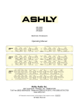
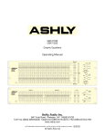
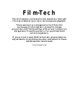
XR 1001
Electronic Crossover
Operating Manual
U
U
U
dB
U
Hz
U
U
dB
Hz
Ashly Audio Inc.
847 Holt Road, Webster, NY 14580-9103
Toll Free (800) 828-6308, Telephone (585) 872-0010, FAX (585) 872-0739
www.ashly.com
All Trademarks referred to herein, are the property of their respective owners. R-1012
All Rights Reserved
Page - 2
Introduction - 2
About Ashly
Safety
XR Crossovers – 3
Connectors & Cables – 3
Physical Description - 4
Installation – 5
Typical Applications - 6
Troubleshooting - 7
Dimensions - 7
Operator Manual – XR 1001 Crossover
Introduction
Congratulations on your purchase of an Ashly XR 1001 Crossover. This crossover is the
product of an intensive research effort which combined a reexamination of traditional
crossover theory with practical field use. Over the years, refinements and new models have
been added to our crossover series, but the original design goals have remained the same: to
produce a crossover which is sonically accurate, is flexible enough to suit a wide variety of
systems, and affords maximum protection for speakers and drivers.
We are confident that you will be pleased with the high performance, superb sound quality,
and reliability that Ashly is known for.
Specifications - 8
About Ashly
Warranty - 9
Ashly Audio was founded in 1974 by a group of recording engineers, sound professionals,
and electronics designers. The first products were custom consoles for friends and
associates, but business quickly grew. The philosophy established from the very beginning
holds true today: to offer only the highest quality audio tools at an affordable cost to the
professional user – ensuring reliability and long life. Many years later, Ashly remains
committed to these principles.
Safety
This manual uses a
Perpetual Table Of
Contents. Each page
has a copy of the
manual’s contents in a
gray box just like this
one. The section you are
in will always be bold
with the other sections
“grayed out.” The feature
allows you to jump
directly to another
section without having to
return to a Table Of
Contents page.
In order to minimize the risk of injury, damage, or hearing loss, please read
the entire owner’s manual before connecting to a sound system.
The lightning flash with arrowhead symbol, within an equilateral triangle, is intended to
alert the user to the presence of uninsulated "dangerous voltage" within the product's
enclosure that may be of sufficient magnitude to constitute a risk of electric shock to
persons. The exclamation point within an equilateral triangle is intended to alert the user
to the presence of important operating and maintenance instructions in the literature
accompanying the device.
TO REDUCE THE RISK OF ELECTRIC SHOCK, DO NOT REMOVE COVER. NO
USER SERVICEABLE PARTS INSIDE.
REFER SERVICING TO QUALIFIED SERVICE PERSONNEL.
TO REDUCE THE RISK OF FIRE OR ELECTRICAL SHOCK, DO NOT EXPOSE THIS
APPLIANCE TO RAIN OR MOISTURE.
TO REDUCE THE RISK OF FIRE, REPLACE ONLY WITH SAME TYPE FUSE.
REFER REPLACEMENT TO QUALIFIED SERVICE PERSONNEL.
WARNING: THIS APPARATUS MUST BE GROUNDED THROUGH THE SUPPLIED
POWER LINE CORD
FCC Compliance
This device complies with part 15 of the FCC Rules. Operation is subject to the following two conditions:
1. This device may not cause harmful interference
2. This device must accept any interference received, including interference that may cause undesired operation
Note: This equipment has been tested and found to comply with the limits for a Class B digital device, pursuant to part 15 of the FCC Rules. These limits are
designed to provide reasonable protection against harmful interference in both a commercial and residential installation. This equipment generates, uses and can
radiate radio frequency energy and, if not installed and used in accordance with the instructions, may cause harmful interference to radio communications. However,
there is no guarantee that interference will not occur in a particular installation. If this equipment does cause harmful interference to radio or television reception,
which can be determined by turning the equipment off and on, the user is encouraged to try to correct the interference by one or more of the following measures:
- Reorient or relocate the receiving antenna.
- Increase the separation between the equipment and receiver.
- Connect the equipment into an outlet on a circuit different from that to which the receiver is connected.
- Consult the dealer or an experienced radio/TV technician for help..
Copyright© 2012 – Ashly Audio Inc.
Operator Manual – XR Series Crossovers
Page - 3
XR Crossovers
Introduction – 2
All Ashly crossovers are based upon the same powerful state-variable filter circuit, which
guarantees that two adjacent frequency band outputs always remain in phase. Our crossovers
offer a number of useful and unusual features, including continuous tuning, a response
control, and a unique output stage, which maintains low noise at any level setting. These
models also include a 200:1 tuning range, output mute switches, and both TRS and XLR
connectors.
Like other Ashly products, your crossover features low noise and distortion, active balanced
inputs, a peak level indicator, a precision regulated power supply, protection against
abnormal input or output conditions, and rugged mechanical construction. Conservative
design and an unusually thorough procedure for quality control have earned Ashly a
reputation for dependability in the recording, sound reinforcement, and broadcast fields.
Connectors & Cables
Your crossover is provided with two different connector types, wired in parallel. 1/4 inch
stereo phone jacks and three pin XLR type connectors will allow interfacing to most
professional audio products, with pin 2 hot
(+) and pin 3 (-). The inputs and outputs can
be used balanced or unbalanced. We
recommend balanced between components in
your system, as this minimizes ground-loop
or induced hum and noise.
If either inputs or outputs are used
unbalanced, the signal is on the (+)
connection and the (-) connection must be
tied to ground. A mono phone plug used as
an unbalanced connection will automatically
ground the ring of the jack which is the (-)
connection. When using a stereo plug or
XLR connector for unbalanced input or
output connections, the signal (-) MUST be
tied to ground, or loss of signal level may
result.
Inputs
Inputs are 20KΩ active balanced, or 10KΩ unbalanced. The inputs of all Ashly crossovers
are in phase with the outputs.
Outputs
The outputs are low impedance (200Ω typical) pseudo-balanced using either connector.
Pseudo-balanced lines have an equivalent line impedance on both (+) and (-) lines,
allowing for long cable runs without compromising common mode rejection of unwanted
noise. For maximum headroom, terminate outputs into loads of 600Ω or greater.
Each model has an additional output labeled MONO LOW OUT. This output represents
the sum of low frequency outputs of both channels, for driving mono sub-woofers in a
stereo system, reducing the number of power amps needed.
All Rights Reserved
XR Crossovers – 3
Connectors & Cables – 3
Inputs
Outputs
Physical Description - 4
Installation – 5
Typical Applications - 6
Troubleshooting - 7
Dimensions - 7
Specifications - 8
Warranty - 9
Page - 4
Operator Manual – XR 1001 Crossover
Introduction - 2
XR Crossovers – 3
Physical Description
Connectors & Cables – 3
Physical Description - 4
Front Panel
Installation – 5
Typical Applications - 6
Troubleshooting - 7
The XR 1001 is 1RU, and weighs approximately 10 pounds.
XR-1001 Front Panel
Dimensions - 7
Specifications - 8
1.
Warranty - 9
2.
3.
4.
CAUTION: High
frequency compression
drivers may be destroyed
by the use of too low a
crossover frequency.
Make sure the range
switch is properly set.
You may want to install a
security cover if the unit
is accessible to untrained
people.
Power - Connects AC power to the unit. Power
is indicated by the frequency range LEDs.
Input Level - boosts incoming signal up to
+8dB before it reaches the filters, or attenuates
the signal to off. Maximum input level is
+23dBu. The “U” shown at the 12:00 position
indicates “unity gain” of the input section.
Crossover Frequency - This infinitely variable
control allows you to select an appropriate
crossover point. A turn clockwise raises the
crossover frequency while counterclockwise
lowers it. Frequencies are marked on standard
ISO 1/3 octave center frequencies with each
octave calibrated. Calibration accuracy is very
good, typically within 1/3 octave or better. If
greater accuracy than this is necessary,
measure the actual crossover frequency with
an accurate oscillator/frequency counter.
To allow a wider tuning range, our crossovers
use a recessed range switch for each
frequency control. LED indicators provide range
status as soon as the unit is powered on. The
range switch divides the frequency indicated on
the frequency control by 10 and gives a total
range of 200:1 for each control. Avoid
accidental damage to speakers by muting the
outputs before changing the range switch.
Response - adjusts the damping of the filter
affecting the response shape of the filters at the
crossover point. The dial calibrations refer to
the amount of attenuation effected by the filter
at the crossover frequency, i.e., a setting of
3dB means that the filter’s high-pass and lowpass outputs are each “rolled off 3dB at the
crossover point”. This describes Butterworth
filter response, or a gentle 3dB peak at the
crossover point where the two filter output
signals overlap. To obtain a flat signal, or
“Linkowitz-Riley” response through the
crossover region, set the Response control to
“6”. To obtain a notch at the crossover point,
turn down the response control past “6” to best
suit your needs. The purpose of this control is
to help offset the inaccuracies inherent in
5.
6.
typical loudspeakers, helping you to achieve a
flat system response.
NOTE: The Response control is not a “slope”
control. The Response control only affects filter
response shape in the immediate vicinity of the
crossover frequency; the ultimate crossover
slope is a fixed parameter.
Output Level - The output stage operates at
unity gain with the output level controls set at
“U”. Max gain of the output stage is +15dB. In a
typical setup, power amplifier input level
controls should be run “full-on”, with level
control being accomplished at the crossover.
Note that horn and compression driver
combinations are much more efficient than
cone speakers, often by 12 to 20dB. When
used together, you should expect a much lower
level setting for the horns to obtain proper
balance. Output mute switches allow you to
isolate individual or grouped outputs for
listening tests without affecting the settings of
any other outputs.
Clip Indicator - Ashly crossovers feature a
peak detection which monitors signal level at
several critical points. The LED will flash when
signal levels of +20dBu are reached anywhere
in the crossover. Since our crossovers have a
nominal 23dB of headroom referenced to a
standard operating level of 0dBu (.77 Volts), a
flashing LED warns you that you are only 3dB
from clipping. Since peak levels are monitored
at several points, the clip LED can be used to
isolate the source. If the LED flashes even
though all input and output levels are turned
down, the signal feed is excessive. If the LED
flashes when you turn the Input level control up
(with the outputs still turned down), the
overload is occurring in the filter sections, and
you should back the Input level down a bit. If
the LED first flashes when you turn the output
level controls up, then the overload is occurring
in the output stage. In this case, if your power
amplifier controls are at full gain, you are
probably severely overdriving your amplifier.
Copyright© 2012 – Ashly Audio Inc.
Operator Manual – XR Series Crossovers
Page - 5
Introduction - 2
XR Crossovers – 3
Connectors & Cables – 3
Physical Description - 4
XR-1001 Back Panel
1. Inputs - For unbalanced inputs, the signal should be on the (+) connection and the (-) connection tied to ground. A
mono 1/4” plug used as an unbalanced connection will automatically be grounded. When using a stereo plug, or XLR
connector for an unbalanced signal, the (-) input connection MUST be tied to ground.
2. Balanced Outputs - This output circuit is an active output which maintains a constant output level between the (+) and
(-) output terminals, regardless of either terminal being connected to ground. This servo-balanced output provides an
unchanged signal without regard to ground.
3. Power – Switches the unit power on or off.
Installation – 5
General Requirements
AC Power
Typical Applications - 6
Troubleshooting - 7
Dimensions - 7
Specifications - 8
Installation
Before connecting to mains power, make sure that the switches are set to the configuration
needed for your particular application. Always switch the crossover off before making
substantial changes to the settings, especially the Range. Failure to do so could result in
damage to the unit or other components in your system. Use four screws and washers when
rack mounting. For mobile use, the unit should be further secured as appropriate.
General Requirements
XR Crossovers have specific physical, electrical and signal requirements for proper
operation. These requirements will vary depending on your specific application, setup, and
the settings on the unit. When setting up and testing your system, please take special care
to double check all connections and settings. Please refer to the specifications section of
this manual for specific input, output and other figures.
AC Power
Your XR Crossover should be connected to a standard 3-wire grounded electrical outlet
supplying 100-240 Volts, 50-60 Hz. To reduce the risk of ground loop hum, connect all
audio equipment to the same electrical power source. Do not remove the AC plug ground
pin, as a potential shock hazard could result.
This unit will perform normally within the AC voltage range specified above. Voltages
less than this, as found in “brown-out” conditions, may reduce performance. No user
serviceable parts are inside the chassis. Refer all servicing to qualified service personnel.
Overall power consumption is less than 30 watts.
NOTE: The power switch does NOT isolate the appliance from mains. Make sure the mains
power socket or an alternative disconnect device is near by and easily accessible. When the
product is connected to mains, the line-filter and the input of the fuse are energized.
All Rights Reserved
Warranty - 9
Page - 6
Introduction - 2
Operator Manual – XR 1001 Crossover
Typical Applications
XR Crossovers– 3
The following information will help you make the most of your new crossover:
Connectors & Cables – 3
Connecting to a Sound System
Physical Description - 4
Usually, the output signal from a final processing source such as a limiter or equalizer is
fed to a crossover input and each crossover output feeds a power amplifier channel.
Sometimes limiters are used on each crossover output to provide more accurate protection.
Installation – 5
Typical Applications - 6
Connecting
Speaker Placement
Stereo 2-Way
Mono 3-Way
Troubleshooting - 7
Dimensions - 7
Specifications - 8
Warranty - 9
Speaker Placement
To obtain maximum benefit from your crossover, a correctly assembled speaker array is a
necessity. Low frequency speakers should be grouped as closely together as possible and
mid and high frequency horns should be stacked on top of one another, not side by side.
This arrangement insures a tight vertical pattern combined with wide horizontal dispersion
free from high frequency lobing. If at all possible, speakers in the array should be arranged
so the drivers and cones are all in the same plane (equal distance from the listener).
XR 1001 Stereo 2-Way Operation
The XR 1001 can be used as a stereo 2-way crossover with an optional mono sub output.
The mono low output is the summed signal from both channel’s low output level controls.
XR 1001 Mono 3-Way Operation
The XR 1001 can also be used as a mono 3-way crossover by pressing in the Mode switch.
Use channel 2 input only. With the Mono 3 Way mode switch pressed in, all active
outputs will have their status LED light up. See illustration for proper use and wiring.
Copyright© 2012 – Ashly Audio Inc.
Operator Manual – XR Series Crossovers
Page - 7
Introduction - 2
Troubleshooting
XR Crossovers – 3
Situation
Action
Connectors & Cables – 3
No Output
Check AC power - are LED indicators on? Check in/out connections, are they reversed? Are
you sure you have input signal?
The level is too high somewhere in the crossover. Try turning down individual output levels
and then the input until the peak LED stays off. If the peak LED continues to flash when all of
the crossover level controls are turned down, then the crossover is being fed excessively
high levels from a previous piece of equipment. Turn down your driving source.
Is the peak light flashing? If it is, an overload is occurring within the crossover, and may also
be occurring in other parts of the system. If the peak light is not flashing, the distortion is
occurring somewhere outside the crossover.
Hum will usually be caused by a “ground loop” between components. Try using the
suggested balanced input and output hookups if the other pieces of equipment used in
conjunction with your crossover have balanced inputs and outputs. Noise can be caused by
insufficient drive signal. Ashly crossovers provide the best noise and headroom performance
when the input signal is 0 to +4dBu level and power amplifier sensitivity is higher than 1 volt.
Unshielded cables, improperly wired connections, and cable with broken strands (shorts,
etc.) are the most common problems. Please properly maintain and inspect your wiring first.
Physical Description - 4
Peak light flashes
frequently
Distorted sound
Excessive hum or noise
Note: Unshielded cables, improperly wired connections, and cable with broken strands
(shorts, etc.) are the most common problems. Make sure you use good quality cable with
connectors soldered firmly on the correct pin. When in doubt, get in touch with your Ashly
dealer.
Dimensions
Inches (Millimeters)
Specifications
Specification
Input Level Control
Damping/Response
Output Level Control
Input Impedance
Output Impedance
Maximum Input Level
Maximum Output Level
Frequency Response
Distortion
Slew Rate
Hum and Noise
Power Requirements
Shipping Weight
Dimensions
XR 1001
-∞ to +8.5 dB
2dB – 12dB
-∞ to +15 dB
20KΩ Balanced
100Ω Servo-Balanced
+23 dBu
+23 dBu
±0.5dB 20Hz-20kHz
<0.05% THD (+10 dBu 20 Hz-20kHz)
6V/µS
<-95dBu unweighted 20 Hz-20kHz
100-240VAC 50-60Hz 30W
85V minimum
10 lbs (4.5kg)
19”L x 1.75”H x 8.5”
(483mm x 44mm x 216mm)
All Rights Reserved
Installation – 5
Typical Applications - 6
Troubleshooting - 7
Dimensions - 7
Specifications - 7
Warranty - 9
Page - 8
Operator Manual – XR 1001 Crossover
Introduction - 2
XR Crossovers – 3
Connectors & Cables – 3
Physical Description - 4
Installation – 5
Typical Applications - 6
Troubleshooting - 7
Dimensions - 7
Specifications - 7
Warranty - 8
Introduction - 2
LIMITED WARRANTY (USA ONLY)
(Other countries please contact your respective distributor or dealer.)
For units purchased in the USA, warranty service for this unit shall be provided by ASHLY
AUDIO, INC. in accordance with the following warranty statement.
ASHLY AUDIO, INC. warrants to the owner of this product that it will be free from defects in
workmanship and materials for a period of FIVE years from the original-date-of-purchase.
ASHLY AUDIO INC. will without charge, repair or replace at its discretion, any defective
product or component parts upon prepaid delivery of the product to the ASHLY AUDIO, INC.
factory service department, accompanied with a proof of original-date-of-purchase in the form
of a valid sales receipt. This warranty gives you specific legal rights, and you may also have
other rights, which vary from state to state.
EXCLUSIONS: This warranty does not apply in the event of misuse, neglect, or as a result of
unauthorized alterations or repairs made to the product. This warranty is void if the serial
number is altered, defaced, or removed. ASHLY AUDIO, INC. reserves the right to make
changes in design, or make additions to, or improvements upon, this product without any
obligation to install the same on products previously manufactured.
Any implied warranties, which may arise under the operation of state law, shall be effective
only for FIVE years from the original-date-of-purchase of the product. ASHLY AUDIO, INC.
shall be obligated to only correct defects in the product itself. ASHLY AUDIO, INC. is not liable
for any damage or injury, which may result from, or be incidental to, or a consequence of, such
defects. Some states do not allow limitations on how long an implied warranty lasts, or the
exclusion, or limitation of incidental or consequential damages, so the above limitations or
exclusions may not apply to you.
OBTAINING WARRANTY SERVICE:
For warranty service in the United States, please follow this procedure:
1) Return the product to ASHLY AUDIO, INC. freight prepaid, with a written statement
describing the defect and application that the product is used in. ASHLY AUDIO, INC. will
examine the product and perform any necessary service, including replacement of defective
parts, at no further cost to you.
2) Ship your product to:
ASHLY AUDIO, INC.
Attention: Service Department
847 Holt Road
Webster, NY 14580-9103
Copyright© 2012 – Ashly Audio Inc.
The PE Series - 3
Physical Descriptio
Installation – 5
Operation – 7
Troubleshooting - 8
Spec Table - 9
Measurements - 10
Dimensions - 11
Warranty - 12