1
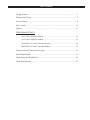
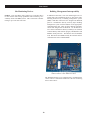
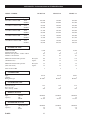
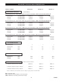
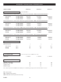
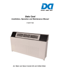
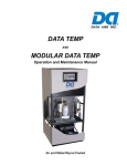
Modular Data Temp Systems Air Cooled Water/Glycol Cooled 8, 10 and 13 ton capacities R-407C ISO 9001 Certified … the pioneer and builder of the most complete line of precision cooling equipment Back in the late 1960’s and early 70’s with the advancement of the computer and computer rooms, precision environmental control equipment with high sensible cooling ratios became a necessity. Data Aire, a division of Supreme Aire, worked with leading computer facility engineers to develop one of the first down discharge air conditioning units for raised floor application. Today, as one of the most experienced manufacturers of precision cooling equipment, Data Aire offers a wide range of precision cooling units with an array of options to meet the specific needs of owners and their projects. Product innovation, to meet the needs of our customers and the industry, has always been a guiding principle at Data Aire. This is demonstrated by our continual product improvements. In the mid 1980’s we were the first to include the steam generator humidifier as standard equipment, eliminating standing water and high maintenance infrared lights. In 1989 Data Aire developed the first solid-state control panel and monitor used in precision cooling and holds the original patent. The Data Alarm Processor (DAP) is well into its second generation, DAP-II. Then in the early to mid 1990’s Data Aire was the first to make scroll compressors standard, introducing them in smaller sizes then gradually across the entire product line. Today these type of compressors are recognized worldwide as the most efficient and reliable compressors available. In 2003 we were awarded an AHR Expo Honorable Mention Innovation Award for our Intelli-DART - a site monitoring device that allows the owner to use the fax, telephone and/or e-mail to monitor their controlled spaces and provides for Internet access to both monitor and modify settings for each individual unit. Finally, in 2005 we are introduced R-410A refrigerant into our product line to meet the 2010 EPA mandates. We are the only manufacturer of precision cooling equipment to make such an offering. Many of our earlier innovations are today’s industry standards among modern manufacturers, and we expect our more recent changes to become industry standards as well. Data Aire produces solutions. We have offered environmental solutions to meet specific needs in the smallest of places and in areas of thousands of square feet. We are prepared to assist you, your in-house engineering department, consulting engineer, or construction department in defining the proper solutions and bringing them to a predefined outcome. Our moderate size, housed in a single facility, allows us to accommodate your special needs quickly and efficiently. Data Aire is committed to being the supplier of choice for precision cooling with the flexibility, reliability, and expertise required to meet our customer’s needs. One of our actions to this commitment is being an ISO 9001 certified company. To be successful, it is essential to be creative and use our resources to their fullest capabilities. Data Aire’s mission is to provide the reliable choice of products and services to our customers Data Aire is a member of the C/S Group of Companies specializing in unique architectural products. The C/S Group of Companies, a private corporation, has been in business since 1949. Data Aire Delivers! MODULAR DATA TEMP Air Cooled Water/Glycol Cooled R-407C Single Circuit Design Compact Size for Easy Maneuverability Product Description Performance/Electrical Data Dimensional Data Guide Specifications Table of Contents Design Features................................................................................................................7 Refrigeration Circuit ........................................................................................................7 System Control ................................................................................................................8 Site Controls ..................................................................................................................10 Options ...........................................................................................................................11 PERFORMANCE DATA Air Cooled • Standard Airflow ..........................................................................12 Air Cooled • Optional Airflow ..........................................................................15 Water/Glycol Cooled • Standard Airflow ..........................................................18 Water/Glycol Cooled • Optional Airflow ..........................................................22 Dimensional and Component Drawings ........................................................................26 Model Identification .......................................................................................................35 Dimensional and Weight Data .......................................................................................36 Guide Specifications ......................................................................................................37 Data Aire, Inc. Modular Data Temp PRECISION COOLING Modular Data Temp Series units are precision environmental control systems that bring a standard of reliable performance to today’s demanding market. Small to large data centers, telecommunication sites, or where access and/or floor space is limited, Modular Data Temp units can meet these demands. Modular Data Temp process cooling systems are available in 8, 10, and 13 nominal ton capacities with upflow or downflow air distribution in air cooled or water/glycol cooled direct expansion models. Each Modular Data Temp unit is factory run tested and put through a vigorous quality control procedure. COMFORT Computer rooms, telecommunication switch sites, and other environmentally controlled spaces require air which is clean and properly distributed, with precisely controlled temperature and humidity. Building or “people comfort” systems are not designed to meet these demands. Modular Data Temp systems are designed to satisfy these goals. DESIGN Modular Data Temp systems feature a specially designed compact tubular steel frame which minimizes the space requirement of air conditioning equipment in the controlled area. Although compact, all parts are easily accessible providing excellent serviceability. Units are finished with a furniture-grade insulated steel cabinet painted in your choice of color. FRAME/CABINET The heliarc welded tubular steel frame provides for maximum strength and ease of access with minimum space requirement. Side and front panels can be easily opened and removed with quarter-turn fasteners, allowing full access to all unit components. All panels include 1 inch thick, 1-1/2 pound density insulation for protection and sound attenuation. All parts are easily accessible. CONTROL The heart of the Modular Data Temp system is the Data Alarm Processor-III (DAP-III), a microprocessor based controller designed for precision environmental control. The DAP-III not only controls and monitors temperature, humidity, airflow, and cleanliness, it provides component runtimes, alarm history, and automatic self-tests. All information is provided on a 2 row, 80 character, backlit liquid crystal display. COIL SECTION Designed for draw through application, the computer selected coil offers greater efficiency in the cooling and dehumidification process. Air bypass is provided to prevent saturated air from being introduced into the controlled space. The coil section is provided with a stainless steel drain pan. DATA AIRE DELIVERS Engineered for high performance and reliability, each Modular Data Temp unit comes with Data Aire’s commitment to excellence. This commitment began with Data Aire’s first process cooling unit and has continued for more than 40 years of building the industry’s finest precision control equipment. Standard ship cycle is 30 days from date of order. With the optional premium “quick ship” program, units can be expedited to ship in as little as one week. All units are built to your specific order. Call your nearest Data Aire representative for more information. FAN SECTION 6 The centrifugal, forward curved, double width, double inlet blower configuration is engineered for quiet reliable operation. The belt driven variable pitch drive provides adjustable air flow capability to match load requirements of the controlled space. The draw through design insures even air distribution across the coil, low internal cabinet losses, and static sealing of the filter section. Motors are mounted on an adjustable slide base and have internal overload protection. Design Features FILTER SECTION Air Cooled with Remote Outdoor Condenser - A wide range of outdoor condensers are available. Condensers are manufactured by Data Aire and sized to meet the heat rejection and ambient conditions as required. The industrial duty design includes aluminum corrosion resistant housing, aluminum finned copper tube coils, powder coated fan guards, energy efficient thermally protected direct drive motors and variable fan speed control on lead fan motor for proper control down to -20° F. Additional fan motors are controlled with ambient thermostats. Units are provided with 4 inch deep, 30% efficient filters (based on ASHRAE Std. 52.1-92). The filter section is accessible from the top or side on downflow units and the right hand side on upflow units. REHEAT Three stage electric reheat is standard. Low-watt density finned tubular sheathed coils are constructed of stainless steel and provide ample capacity to maintain room dry bulb conditions during dehumidification. Low-watt density coils eliminate ionization associated with open air electric resistance heating. Air Cooled with Indoor Condenser - A wide range of floor mounted indoor condensers with horizontal intake and discharge are available for applications where an outdoor condenser cannot be used. Finished to match the indoor evaporator section, the condenser includes a centrifugal, forward curved, double width, double inlet blower engineered for quiet, reliable operation. The belt driven variable pitch drive provides adjustable air flow. The motor has internal overload protection and is mounted on an adjustable slide base. Indoor condensers are provided with a factory mounted and piped receiver, complete with a head pressure control valve to maintain head pressure under varying ambient conditions down to -30° F. HUMIDIFICATION Modular Data Temp units include an electric steam generator humidifier with a “quick change” disposable cylinder and an auto-flush cycle. The steam generator humidifier with its patented control system optimizes cylinder life and energy efficiency by concentrating incoming water to a predetermined conductivity much higher than that of the entering water. The control system continuously monitors the conductivity in the cylinder through its electronics which allows water to be flushed as often as is necessary to maintain the capacity at this design conductivity. The high design conductivity results in a minimum flushing of heated water, thereby saving energy. The humidifier is designed to allow units at any voltage to produce full rated steam output capacity at an optimum water level based on the design conductivity. Air Cooled with Outdoor Condensing Unit - When compressors are required to be out of the controlled space, Modular Data Temp units are available with a remote outdoor condensing unit. The condensing unit includes a hermetic scroll compressor with built-in overload protection, crankcase heater, filter drier, sight-glass and condenser coil. The coil is constructed with copper tubes and aluminum fins. The housing is corrosion resistant aluminum with vertical air discharge. The condenser fan is a variable speed type for head pressure control down to -20° F ambient temperature. Additional fan motors are controlled by ambient fan thermostats. REFRIGERATION CIRCUIT The single circuit, refrigeration circuit is designed around a high efficiency hermetic scroll compressor. These durable, heavy duty, fully welded compressors have no gaskets or seals, substantially reducing the possibility of refrigerant or oil leaking into the controlled space or environment. Scroll compressors bring a combination of reliability, efficiency and improved system sound performance to the Modular Data Temp line. The refrigeration circuit includes built-in compressor overload protection, crankcase heater, filter drier, sight-glass, adjustable expansion valve with external equalizer, low pressure override timer (air cooled units), manual reset high pressure control, compressor short cycle timer, and rotolock service valves. Water/glycol cooled units include a counterflow plate-fin condenser sized to provide the required heat of rejection with minimum water/glycol flow for a low total pressure drop. Head pressure water regulating valves control the condenser water flow to maintain proper head pressure under varying load conditions. Water/Glycol Cooled with Remote Outdoor Fluid Cooler - Remote outdoor fluid coolers are available in a variety of sizes. Each fluid cooler includes aluminum corrosion resistant housing, aluminum finned copper tube coil, coated fan guards, surge tank, motor contactor, pump contactor and energy efficient thermally protected direct drive motors. Multiple fan motors are staged to maintain the desired condenser supply fluid temperature. 7 Control System DATA ALARM PROCESSOR-III The Data Alarm Processor-III (DAP™ III) offers the definitive answer for precision environmental control. The DAP-III control system not only controls and monitors temperature, humidity, airflow and cleanliness, it provides component run times, alarm history and an automatic self-test of the microprocessor on system start-up. All messages are presented in a clear vernacular format and sequentially displayed on a backlit, liquid crystal display (LCD). OPERATION – Highly reliable, flat, sealed switches with tactile feedback allow unit on/off operation, menu selection for programming, operational information, diagnostics, and historical data. Multilevel password prevents unauthorized access. Alarm conditions are enunciated by an audible alarm. The alarm silence button will quiet the audible alarm but the display will continue to indicate the alarm condition until the problem is corrected. STANDARD FEATURES Two row, eight character, backlit LCD screen Programmed settings saved in flash memory Smooth keyboard type buttons Real time clock with back-up battery Forward and backward menu access Data base of unit and room conditions Factory calibrated humidity sensor Factory calibrated temperature sensor Power “ON” status contact Stand alone panel Microprocessor based Automatic self-test diagnostics USB port for software upgrades All settings from face of panel Multi-level password access Battery backup for historical data Menus factory programmed OPERATIONAL FEATURES Automatic or manual restart Automatic reheat element rotation Adjustable mode and stage response time Chilled water energy saver coil flush cycle Compressor short cycle control on DX units Start time delay Automatic compressor rotation Hot water coil flush cycle Humidity anticipation Sequential load activation Dehumidification mode lockout OPTIONAL FEATURES Energy saver (glycol) or auxiliary chilled water operation Periodical DX activation on Energy Saver system Supplemental compressor in Energy Saver mode Chilled water temperature sensor Four analog inputs (4-20 mA or 0-10 VDC signal) Two analog outputs (0-10 VDC signal) Underfloor water detection cable Fan speed control for optional plug fan or VFD Humidifier auto-flush cycle Three additional remote alarms Discharge air temperature sensor Modulating humidifier control RS-485 Multi-drop network card Ethernet network card LONTALK network card DIAGNOSTIC and SERVICE FEATURES Alarms displayed in order of occurrence Manual diagnostic program Programmable delays for optional alarms Adjustable alarm limits Programmable remote alarm contact Select alarms optional disabled Four programmable optional alarm inputs Selectable audio alarm tone Manual override for blower, cool 1/2, reheat 1, humidification and water valve 8 Control System PROTECTIVE and SAFETY FEATURES Metal shell enclosure with sealed front control panel Opto-coupler signal inputs Heavy ground planes and power foils Switching power supply Watch dog timer Protected 24VAC power input Isolation transformer Fuses on all control boards CONDITIONS and DATA DISPLAYED Current percent of capacity utilized Current temperature Current humidity Current discharge air temperature* Current chilled water temperature* Cooling stages Reheat stages Chilled water flow percentage Temperature setpoint Humidity setpoint Unit or network identification number* Zone number* FUNCTIONS DISPLAYED Energy Saver* Dehumidification Humidification ALARMS High temperature warning High humidity warning High pressure/internal overload compressor 1 High pressure/internal overload compressor 2 Under floor water detection Firestat tripped, unit shutdown Custom message (programmed by factory)* Chilled water temperature sensor problem* Low voltage warning Compressor short-cycle Humidity sensor problem Local alarm* Check humidifier cylinder* No water flow* Standby pump on* Low temperature warning Low humidity warning Low pressure compressor 1 Low pressure compressor 2 No air flow Dirty filter alarm Humidity failure Manual override Power failure restart Temperature sensor problem Maintenance required Discharge air sensor problem* Fan motor overload* Smoke detector, unit shutdown* Person to contact on alarm* HISTORICAL DATA Equipment run times High and low temperature in last 24 hours Average percent of capacity last hour Alarm history for last ten alarms High and low humidity in last 24 hours PROGRAMMABLE SETTINGS and SELECTIONS The user friendly Menus and Select buttons used with the 10 menu groups permit step-by-step programming of many functions. The DAP III Operation Manual provides a complete and detailed guide to the settings and selections. Refer to it for specific ranges and settings. * - May require additional components and/or sensors. 9 Site Control Site Monitoring Devices Building Management Interoperability DARA-4 - Data Aire Relay Auto Changeover controller allows for unit rotation and backup capabilities while interfacing via a summary alarm with BMS systems. This economical controller manages up to four Data Aire units. In addition to Data Aire’s own site monitoring devices we realize that some installations prefer to have their entire building monitored by a building management system (BMS). With this in mind we have designed our DAP-III panel to communicate directly with any major building management system with the addition of the appropriate communications card. There are three different communication cards designed for the DAP III. Use the RS-485 2 wire card to communicate directly to Metasys N2 (Johnson Controls Metasys and Siemens Apogee), Modbus RTU and Modbus ASCII protocols. The Ethernet card for Modbus TCP, BACnet IP and SNMP. Finally the Lontalk card for communication with LonWorks BMS. Shown above is the Ethernet card. The DAP-III panel has to be equipped with a communications card in order to communicate with each of the site monitoring devices listed above. 10 Options Remote Temperature and Humidity Sensors - Temperature and humidity sensors may be ordered for remote wall mounting. Sensors are provided in a wall mount plastic case for remote sensing of temperature and humidity. 25 feet of shielded cable is provided for field wiring. Smoke Detector - A unit mounted smoke detector will shut down the unit if smoke is sensed. The unit mounted microprocessor will sound an alarm and display “SMOKE DETECTOR: UNIT SHUTDOWN” message. The smoke detector is mounted in the return air stream and is provided with auxiliary contacts. Unit Mounted Disconnect - A unit mounted non-automatic disconnect switch is installed in the high voltage electrical section. The operating mechanism prevents access to the high voltage electrical components until switched to the “OFF” position. The operating mechanism (handle) protrudes through the decorative door. Steam Generator Humidifier with Modulating Control Modulating control may be added to the steam generator humidifier. Modulating control will allow the humidifier to automatically adjust steam output to match changing room conditions. Self-regulating auto flush is included. 3-Way Water Regulating Valve - A 3-way water regulating valve for head pressure control may be ordered to replace standard 2-way valve installed in unit. The 3-way valve controls the water/glycol flow rate to meet the heat rejection requirements under varying conditions. Recommended on units with dual pump applications. Condensate Pump - Condensate pumps may be ordered as factory installed or for field installation. Condensate pumps are complete with sump, motor, and automatic control. The pumps are rated for 130 GPH @ 20 ft maximum or 40 GPH @ 20 feet with check valve. Pumps shipped loose are available in 115, 230, or 460 volt. If unit mounted and wired, the pump will match the unit voltage. Not available in 575 volt. Upflow Plenum - Upflow plenums are fully insulated and have front discharge air grille. Side grilles for both or one side are available. Plenums are 18 inches high and are painted to match the unit color. Floorstand - Floorstands are adjustable +/- 2 inches and may be ordered with a factory installed turning vane or with seismic construction. 60% Efficient Filter - The standard 30% efficient filter may be replaced with 60% efficient filter (based on ASHRAE Std. 52.1-1992). Filters are 4 inch deep, pleated type. (Note: Higher efficiency filters are available - consult factory regarding efficiency percentage and unit static pressures) 1” Pre-Filter - Units may be ordered with a one inch pre-filter. Pump Package - Centrifugal pump packages are available to circulate water or water/glycol solution. Pumps are available in various horsepower and voltage. Both 3400 and 1750 rpm pumps are available as an option. Pumps ship loose or come mounted in an optional pump enclosure. It is recommended on units with dual pump applications that a 3-way water regulating valve be used in lieu of the standard 2-way valve. Pump Auto-Changeover - Dual pump packages may be provided with a pump auto-changeover control and NEMA 4 flow switch (field installed). The pump auto-changeover control is factory wired and mounted in the dry cooler control box. The pump auto-changeover control provides automatic pump changeover in the event of a pump failure. Upon pump changeover, an audible alarm will sound at the indoor unit and a message (“STANDBY PUMP ON: CHECK PRIMARY PUMP”) will be displayed on the unit microprocessor display. Hot Gas Bypass - Hot gas bypass may be ordered for changing load conditions. The hot gas bypass valve is installed between the compressor discharge line and the leaving side of the expansion valve through a side outlet distributor. The system with the evaporator under full load will maintain pressure on the leaving side of the hot gas bypass valve to keep the valve port closed. Should the load on the evaporator decrease to the point where the coil is below the desired setting, the pressure on the discharge of the hot gas bypass will put pressure on the diaphragm overcoming the spring pressure of the seat and allowing some hot gas to mix with the normal liquid discharge of the expansion valve raising the evaporator pressure. This reduces the cooling capacity of the unit to match the load. The hot gas bypass valve can be adjusted to “fine tune” the unit to room conditions. Pump Enclosures - Pump enclosures are available for either single or dual pump applications*. Pump enclosures are vented and weather resistant. When ordered with pumps, the pumps are factory mounted in the enclosure ready for field piping and wiring. (* Due to the size of some pumps, a special oversized enclosure can be made available.) Integral Pump Enclosures - Pumps may be factory mounted as an integral part of the dry cooler. A 30” extension is added to the dry cooler. Pumps are pre-piped and wired. Shut-off valves and flow switches are included. This configuration greatly reduces field installation procedures. Extended Compressor Warranty - Extended compressor warranty is available from the manufacturer in addition to the standard warranty. The warranty is for replacement of compressors and does not include labor. Contact you local representative for period of coverage. 11 AIR COOLED: Performance data at STANDARD airflow MODEL NUMBER DTAD/U-08 DTAD/U-10 DTAD/U-13 CAPACITY in Btu/hr - gross 80° DB/67° WB 50% RH Total Sensible 105,800 84,000 134,000 100,000 163,800 119,000 75° DB/62.5° WB 50% RH Total Sensible 98,000 81,000 124,500 97,000 152,000 115,500 75° DB/61° WB 45% RH Total Sensible 95,100 86,800 121,200 103,400 147,600 122,800 72° DB/60° WB 50% RH Total Sensible 93,300 79,300 118,900 95,100 145,000 113,300 72° DB/58.6° WB 45% RH Total Sensible 90,900 84,600 115,900 101,100 141,100 120,100 3,600 2 0.5 1/1 4,000 3 0.5 1/1 4,500 3 0.5 1/1 BLOWER SECTION Airflow in CFM Standard motor HP External static pressure - inches of W.G. Number of motors/fans Maximum external static pressure (Standard motor) Downflow Upflow 0.8 0.8 1.5 1.5 0.6 0.6 Maximum external static pressure (Next size motor) Downflow Upflow 1.5 1.5 1.5 1.5 1.5 1.5 3 5 5 Scroll 1 R-407C Scroll 1 R-407C Scroll 1 R-407C 12.2 3 295 12.2 4 328 12.2 5 369 Standard 15 51,225 Standard 15 51,225 Standard 15 51,225 Standard 3.2 10 Standard 3.2 10 Standard 3.2 10 Next size motor HP COMPRESSORS Type Quantity Refrigerant type EVAPORATOR COIL Face are in sq. ft. Rows of coils Face velocity - FPM REHEAT SECTION Type Capacity Electric kW Btu/hr HUMIDIFIER SECTION Type Capacity R-407C Steam generator kW lbs/hr 12 AIR COOLED: Performance data at STANDARD airflow MODEL NUMBER DTAD/U-08 ELECTRICAL SECTION DTAD/U-10 DTAD/U-13 Standard Motor Electrical data based on: electric reheat- YES, steam generator humidifier - YES, and STANDARD MOTOR. 208-230/3/60 460/3/60 575/3/60 FLA/MCA/MOP FLA/MCA/MOP FLA/MCA/MOP 77/94/110 37/45/50 28/35/40 88/108/125 40/50/60 31/38/45 100/123/150 46/56/70 38/46/60 Electrical data based on: electric reheat - NO, steam generator humidifier - YES, and STANDARD MOTOR. 208-230/3/60 460/3/60 575/3/60 FLA/MCA/MOP FLA/MCA/MOP FLA/MCA/MOP 51/63/80 25/31/40 19/23/30 63/76/100 29/35/50 22/26/35 75/91/125 34/42/60 28/35/50 Electrical data based on: electric reheat - YES, steam generator humidifier - NO, and STANDARD MOTOR. 208-230/3/60 460/3/60 575/3/60 FLA/MCA/MOP FLA/MCA/MOP FLA/MCA/MOP 77/94/110 37/45/50 28/35/40 88/108/125 40/50/60 31/38/45 100/123/150 46/56/70 38/46/60 Electrical data based on: electric reheat - NO, steam generator humidifier - NO, and STANDARD MOTOR. 208-230/3/60 460/3/60 575/3/60 FLA/MCA/MOP FLA/MCA/MOP FLA/MCA/MOP 35/42/70 18/22/35 13/16/25 46/56/90 22/26/40 16/19/30 58/71/110 27/32/50 23/27/45 2 3 3 FLA FLA FLA 6.2 3.1 2.5 9.0 4.4 3.3 9.0 4.4 3.3 FLA FLA FLA 28.8 14.7 10.8 37.2 17.2 12.4 49.4 22.4 19.2 STANDARD MOTOR Motor horsepower 208-230/3/60 460/3/60 575/3/60 COMPRESSOR 208-230/3/60 460/3/60 575/3/60 AIR COOLED CONDENSER Remote mounted outdoors Condenser selection at 95° F ambient DARC-09 DARC-11 DARC-15 Condenser selection at 100° F ambient DARC-11 DARC-15 DARC-17 Condenser selection at 105° F ambient DARC-15 DARC-17 DARC-21 Note: Condensers are selected at sea level. Refer to page 30 for electrical data. FLA - Full Load Amps MCA - Minimum Circuit ampacity (wire sizing amps) MOP - Maximum overcurrent protection device amp 13 R-407C AIR COOLED: Performance data at STANDARD airflow MODEL NUMBER DTAD/U-08 ELECTRICAL SECTION DTAD/U-10 DTAD/U-13 Next Size Motor Electrical data based on: electric reheat - YES, steam generator humidifier - YES, and NEXT SIZE MOTOR. 208-230/3/60 460/3/60 575/3/60 FLA/MCA/MOP FLA/MCA/MOP FLA/MCA/MOP 80/97/110 38/46/50 29/36/40 94/113/125 43/52/60 33/40/45 106/129/150 48/58/70 40/48/60 Electrical data based on: electric reheat - NO, steam generator humidifier - YES, and NEXT SIZE MOTOR. 208-230/3/60 460/3/60 575/3/60 FLA/MCA/MOP FLA/MCA/MOP FLA/MCA/MOP 54/65/90 27/32/45 20/24/30 68/82/110 31/37/50 24/28/35 80/97/125 36/44/60 30/37/50 Electrical data based on: electric reheat - YES, steam generator humidifier - NO, and NEXT SIZE MOTOR. 208-230/3/60 460/3/60 575/3/60 FLA/MCA/MOP FLA/MCA/MOP FLA/MCA/MOP 80/97/110 38/46/50 29/36/40 94/113/125 43/52/60 33/40/45 106/129/150 48/58/70 40/48/60 Electrical data based on: electric reheat - NO, steam generator humidifier - NO, and NEXT SIZE MOTOR. 208-230/3/60 460/3/60 575/3/60 FLA/MCA/MOP FLA/MCA/MOP FLA/MCA/MOP 38/45/70 19/23/35 14/17/25 52/61/90 24/28/45 18/21/30 64/76/125 29/35/50 25/29/45 3 5 5 9.0 4.4 3.3 14.6 6.6 5.3 14.6 6.6 5.3 2 - 20x25x4 2 - 20x25x4 2 - 20x25x4 5/8 3/4 3/4 1/4 5/8 3/4 3/4 1/4 5/8 3/4 3/4 1/4 NEXT SIZE MOTOR Motor horsepower 208-230/3/60 460/3/60 575/3/60 FILTER SECTION FLA FLA FLA (Pleated, 30% efficient, based on ASHRAE Std. 52.1-1992) Quantity/size CONNECTION SIZES Liquid line - O.D. copper Hot gas line - O.D. copper Condensate drain Humidifier supply (Note: Refer to Operation and Maintenance Manual for recommended pipe sizing between unit and condenser section.) FLA - Full load amps MCA - Minimum circuit ampacity MOP - Maximum overcurrent protection device amps R-407C 14 AIR COOLED: Performance data at OPTIONAL airflow MODEL NUMBER DTAD/U-08 DTAD/U-10 DTAD/U-13 CAPACITY in Btu/hr - gross 80° DB/67° WB 50% RH Total Sensible 108,700 94,000 138,700 113,200 168,800 132,700 75° DB/62.5° WB 50% RH Total Sensible 101,000 90,600 129,300 109,600 156,800 128,400 75° DB/61° WB 45% RH Total Sensible 98,100 96,100 125,200 117,300 152,400 137,400 72° DB/60° WB 50% RH Total Sensible 96,300 88,500 123,700 107,500 149,700 125,800 72° DB/58.6° WB 45% RH Total Sensible 93,600 92,600 119,900 114,400 145,800 134,000 4,400 3.0 0.5 1/1 5,000 5.0 0.5 1/1 5,500 5.0 0.5 1/1 BLOWER SECTION Airflow in CFM Standard motor HP External static pressure - inches of W.G. Number of motors/fans Maximum external static pressure (Standard motor) Downflow Upflow 1 1 1.5 1.5 0.8 0.8 Maximum external static pressure (Next size motor) Downflow Upflow 1.5 1.5 1.5 1.5 0.8 0.8 5 7.5 7.5 Scroll 1 R-407C Scroll 1 R-407C Scroll 1 R-407C 12.2 3 361 12.2 4 410 12.2 5 451 Standard 15 51,225 Standard 15 51,225 Standard 15 51,225 Standard 3.2 10 Standard 3.2 10 Standard 3.2 10 Next size motor HP COMPRESSORS Type Quantity Refrigerant type EVAPORATOR COIL Face area in sq. ft. Rows of coils Face velocity - FPM REHEAT SECTION Electric Capacity kW Btu/hr HUMIDIFIER SECTION Steam generator Capacity kW lb/hr 15 R-407C AIR COOLED: Performance data at OPTIONAL airflow MODEL NUMBER DTAD/U-08 ELECTRICAL SECTION DTAD/U-10 DTAD/U-13 Standard motor Electrical data based on: electric reheat - YES, steam generator humidifier - YES, and STANDARD MOTOR. 208-230/3/60 460/3/60 575/3/60 FLA/MCA/MOP FLA/MCA/MOP FLA/MCA/MOP 80/97/110 38/46/50 29/36/40 94/113/125 43/52/60 33/40/45 106/129/150 48/58/70 40/48/60 Electrical data base on: electric reheat - NO, steam generator humidifier - YES, and STANDARD MOTOR. 208-230/3/60 460/3/60 575/3/60 FLA/MCA/MOP FLA/MCA/MOP FLA/MCA/MOP 54/65/90 27/32/45 20/24/30 68/82/110 31/37/50 24/28/35 80/97/125 36/44/60 30/37/50 Electrical data based on: electric reheat - YES, steam generator humidifier - NO, and STANDARD MOTOR. 208-230/3/60 460/3/60 575/3/60 FLA/MCA/MOP FLA/MCA/MOP FLA/MCA/MOP 80/97/110 38/46/50 29/36/40 94/113/125 43/52/60 33/40/45 106/129/150 48/58/70 40/48/60 Electrical data based on: electric reheat - NO, steam generator humidifier - NO, and STANDARD MOTOR. 208-230/3/60 460/3/60 575/3/60 FLA/MCA/MOP FLA/MCA/MOP FLA/MCA/MOP 38/45/70 19/23/35 14/17/25 52/61/90 24/28/45 18/21/30 64/76/125 29/35/50 25/29/45 3 5 5 FLA FLA FLA 9.0 4.4 3.3 14.6 6.6 5.3 14.6 6.6 5.3 FLA FLA FLA 28.8 14.7 10.8 37.2 17.2 12.4 49.4 22.4 19.2 STANDARD MOTOR Motor horsepower 208-230/3/60 460/3/60 575/3/60 COMPRESSOR 208-230/3/60 460/3/60 575/3/60 AIR COOLED CONDENSER Remote mounted outdoors Condenser selection at 95° F ambient DARC-09 DARC-11 DARC-15 Condenser selection at 100° F ambient DARC-11 DARC-15 DARC-17 Condenser selection at 105° F ambient DARC-15 DARC-17 DARC-21 (Note: Condensers are selected at sea level. Refer to page 30 for electrical data) FLA - Full load amps MCA - Minimum circuit ampacity MOP - Maximum overcurrent protection device amps R-407C 16 AIR COOLED: Performance data at OPTIONAL airflow MODEL NUMBER DTAD/U-08 ELECTRICAL SECTION DTAD/U-10 DTAD/U-13 Next size motor Electrical data base on: electric reheat - YES, steam generator - YES, and NEXT SIZE MOTOR. 208-230/3/60 460/3/60 575/3/60 FLA/MCA/MOP FLA/MCA/MOP FLA/MCA/MOP 85/103/110 40/49/50 31/38/45 102/122/125 47/56/60 36/43/50 114/137/175 52/63/80 43/51/60 Electrical data base on: electric reheat - NO, steam generator humidifier - YES, and NEXT SIZE MOTOR. 208-230/3/60 460/3/60 575/3/60 FLA/MCA/MOP FLA/MCA/MOP FLA/MCA/MOP 60/71/90 29/34/45 22/26/35 77/90/110 36/42/50 27/32/40 89/105/150 41/48/60 34/40/50 Electrical data based on: electric reheat - YES, steam generator humidifier - NO, and NEXT SIZE MOTOR. 208-230/3/60 460/3/60 575/3/60 FLA/MCA/MOP FLA/MCA/MOP FLA/MCA/MOP 85/103/110 40/49/50 31/38/45 102/122/125 47/56/60 36/43/50 114/137/175 52/63/80 43/51/60 Electrical data based on: electric reheat - NO, steam generator humidifier - NO, and NEXT SIZE MOTOR. 208-230/3/60 460/3/60 575/3/60 FLA/MCA/MOP FLA/MCA/MOP FLA/MCA/MOP 43/51/70 21/25/40 16/19/30 60/70/100 28/33/50 21/24/35 72/85/125 33/39/60 28/33/50 5 7.5 7.5 14.6 6.6 5.3 23.0 11.0 8.6 23.0 11.0 8.6 NEXT SIZE MOTOR Motor horsepower 230/3/60 460/3/60 575/3/60 FILTER SECTION FLA FLA FLA (Pleated, 30% efficient based on ASHRAE Std. 52.1-1992.) Quantity/size 3 - 16x25x4 3 - 16x25x4 3 - 16x25x4 5/8 3/4 3/4 1/4 5/8 3/4 3/4 1/4 5/8 3/4 3/4 1/4 CONNECTION SIZES Liquid line - O.D. copper Hot gas line - O.D. copper Condensate drain Humidifier supply (Note: Refer to Operation and Maintenance Manual for recommended pipe sizing between unit and condenser section) FLA - Full load amps MCA - Minimum circuit ampacity MOP - Maximum overcurrent protection device amps 17 R-407C WATER COOLED: Performance at STANDARD airflow MODEL NUMBER DTWD/U-08 DTWD/U-10 DTWD/U-13 Total Sensible 109,900 85,500 139,400 102,100 170,200 121,600 75° DB/62.5° WB 50% RH Total Sensible 102,000 82,700 129,600 99,100 158,100 118,100 CAPACITY in Btu/hr - gross 80° DB/67° WB 50% RH 75° DB/61° WB 45% RH Total Sensible 99,300 88,500 126,600 105,800 153,800 125,600 72° DB/60° WB 50% RH Total Sensible 97,200 81,000 123,600 97,300 150,700 116,000 72° DB/58.6° WB 45% RH Total Sensible 94,900 86,400 121,100 103,500 146,900 122,800 GLYCOL COOLED: Performance at STANDARD airflow MODEL NUMBER DTGD/U-08 DTGD/U-10 DTGD/U-13 CAPACITY in Btu/hr - gross 80° DB/67° WB 50% RH Total Sensible 103,100 82,900 131,300 99,000 159,600 117,400 75° DB/62.5° WB 50% RH Total Sensible 95,600 80,100 122,000 95,900 148,400 113,900 75° DB/61° WB 45% RH Total Sensible 92,800 85,800 119,100 102,600 144,300 121,400 72° DB/60° WB 50% RH Total Sensible 91,100 78,400 116,400 94,100 141,700 111,800 72° DB/58.6° WB 45% RH Total Sensible 88,600 83,600 114,000 100,200 138,000 118,600 3,600 2 0.5 1/1 4,000 3 0.5 1/1 4,500 3 0.5 1/1 BLOWER SECTION Airflow in CFM Standard motor HP External Static Pressure - inches of W.G. Number of motors/fans Maximum external static pressure (Standard motor) Downflow Upflow 0.8 0.8 1.5 1.5 0.6 0.6 Maximum external static pressure (Next size motor) Downflow Upflow 1.5 1.5 1.5 1.5 1.5 1.5 3 5 5 Next size motor - horsepower R-407C 18 WATER/GLYCOL COOLED: Performance data at STANDARD airflow CONDENSER WATER Using 65° F EWT Using 75° F EWT Using 85° F EWT Using Fluid Cooler (Maximum design water pressure 150 psi - High pressure valves optional) GPM Pressure drop in PSI GPM Pressure drop in PSI GPM Pressure drop in PSI GPM Pressure drop in PSI 9.5 4.1 14.8 4.5 21 7.1 28.0 9.1 11.9 4.1 18.5 4.5 26.3 7.1 35.0 10.1 14.8 3.5 23.2 4.1 31.8 4.5 43.0 8.1 Scroll 1 R-407C Scroll 1 R-407C Scroll 1 R-407C 12.2 3 295 12.2 4 328 12.2 5 369 Standard 15 51,225 Standard 15 51,225 Standard 15 51,225 Standard 3.2 10 Standard 3.2 10 Standard 3.2 10 COMPRESSORS Type Quantity Refrigerant EVAPORATOR COIL Face area - sq. ft. Rows of coils Face velocity in FPM REHEAT SECTION Electric kW Capacity in Btu/hr HUMIDIFIER SECTION Steam generator kW Capacity in lb/hr FILTER SECTION Quantity/size CONNECTION SIZES Condenser water - supply Condenser water - return Condensate drain Humidifier supply (Pleated, 30% efficient based on ASHRAE Std. 52.1-1992.) 2 - 20x25x4 2 - 20x25x4 2 - 20x25x4 (Refer to Operation and Maintenance Manual for piping information between unit and dry cooler) 1-5/8 1-5/8 3/4 1/4 19 1-5/8 1-5/8 3/4 1/4 1-5/8 1-5/8 3/4 1/4 R-407C WATER/GLYCOL COOLED: Performance data at STANDARD airflow MODEL NUMBER DT*D/U-08 ELECTRICAL SECTION DT*D/U-10 DT*D/U-13 Standard Motor Electrical data based on: electric reheat - YES, steam generator humidifier YES, and STANDARD MOTOR. 208-230/3/60 460/3/60 575/3/60 FLA/MCA/MOP FLA/MCA/MOP FLA/MCA/MOP 77/94/110 37/45/50 28/35/40 88/108/125 40/50/60 31/38/45 100/123/150 46/56/70 38/46/60 Electrical data base on: electric reheat - NO, steam generator humidifier - YES, and STANDARD MOTOR. 208-230/3/60 460/3/60 575/3/60 FLA/MCA/MOP FLA/MCA/MOP FLA/MCA/MOP 51/63/80 25/31/40 19/23/30 63/76/100 29/35/50 22/26/35 75/91/125 34/42/60 28/35/50 Electrical data based on: electric reheat - YES, steam generator humidifier - NO, and STANDARD MOTOR. 208-230/3/60 460/3/60 575/3/60 FLA/MCA/MOP FLA/MCA/MOP FLA/MCA/MOP 77/94/110 37/45/50 28/35/40 88/108/125 40/50/60 31/38/45 100/123/150 46/56/70 38/46/60 Electrical data based on: electric reheat - NO, steam generator humidifier - NO, and STANDARD MOTOR. 208-230/3/60 460/3/60 575/3/60 FLA/MCA/MOP FLA/MCA/MOP FLA/MCA/MOP 35/42/70 18/22/35 13/16/25 46/56/90 22/26/40 16/19/30 58/71/110 27/32/50 23/27/45 2 3 3 FLA FLA FLA 6.2 3.1 2.5 9.0 4.4 3.3 9.0 4.24 3.3 FLA FLA FLA 28.8 14.7 10.8 37.2 17.2 12.4 49.4 22.4 19.2 STANDARD MOTOR Motor horsepower 208-230/3/60 460/3/60 575/3/60 COMPRESSOR 208-230/3/60 460/3/60 575/3/60 * - W for water or G for glycol FLA - Full load amps MCA - Minimum circuit amps (wire sizing amps) MOP - Maximum overcurrent protection device amps R-407C 20 WATER/GLYCOL COOLED: Performance data at STANDARD airflow MODEL NUMBER DT*D/U-08 ELECTRICAL SECTION DT*D/U-10 DT*D/U-13 Next Size Motor Electrical data based on: electric reheat - YES, steam generator humidifier - YES, and NEXT SIZE MOTOR. 208-230/3/60 460/3/60 575/3/60 FLA/MCA/MOP FLA/MCA/MOP FLA/MCA/MOP 80/97/110 38/46/50 29/36/40 94/113/125 43/52/60 33/40/45 106/129/150 48/58/70 40/48/60 Electrical data based on: electric reheat - NO, steam generator humidifier - YES, and NEXT SIZE MOTOR. 208-230/3/60 460/3/60 575/3/60 FLA/MCA/MOP FLA/MCA/MOP FLA/MCA/MOP 54/65/90 27/32/45 20/24/30 68/82/110 31/37/50 24/28/35 80/97/125 36/44/60 30/37/50 Electric data based on: electric rehear - YES, steam generator humidifier - NO, and NEXT SIZE MOTOR. 208-230/3/60 460/3/60 575/3/60 FLA/MCA/MOP FLA/MCA/MOP FLA/MCA/MOP 80/97/110 38/46/50 29/36/40 94/113/125 43/52/60 33/40/45 106/129/150 48/58/70 40/48/60 Electrical data based on: electric reheat - NO, steam generator humidifier -NO, and NEXT SIZE MOTOR. 230/3/60 460/3/60 575/3/60 FLA/MCA/MOP FLA/MCA/MOP FLA/MCA/MOP 38/45/70 19/23/35 14/17/25 52/61/90 24/28/45 18/21/30 64/76/125 29/35/50 25/29/45 3 5 5 9.0 4.4 3.3 14.6 6.6 5.3 14.6 6.6 5.3 Dry cooler selection at 95° F ambient DAFC-15 DAFC-21 DAFC-21 Dry cooler selection at 100° F ambient DAFC-21 DAFC-24 DAFC-30 NEXT SIZE MOTOR Motor horsepower 203-230/3/60 460/3/60 575/3/60 FLA FLA FLA OUTDOOR DRY COOLER (Note: Dry coolers are selected at sea level. Refer to page 32 for dry cooler electrical data) * - W for water or G for glycol FLA - Full load amps MCA - Minimum circuit amps (wire sizing amps) MOP - Maximum overcurrent protection device amps 21 R-407C WATER COOLED: Performance data at OPTIONAL airflow MODEL NUMBER DTWD/U-08 DTWD/U-10 DTWD/U-13 CAPACITY in Btu/hr - gross 80° DB/67° WB 50% RH Total Sensible 113,600 95,700 144,100 115,300 176,300 135,600 75° DB/62.5° WB 50% RH Total Sensible 105,500 92,400 134,100 111,600 163,500 131,200 75° DB/61° WB 45% RH Total Sensible 102,000 98,600 130,400 119,500 158,600 140,000 72° DB/60° WB 50% RH Total Sensible 100,700 90,400 128,100 109,300 155,800 128,500 72° DB/58.6° WB 45% RH Total Sensible 97,500 95,600 124,800 116,600 151,500 136,600 GLYCOL COOLED: Performance data at OPTIONAL airflow MODEL NUMBER DTGD/U-08 DTGD/U-10 DTGD/U-13 CAPACITY in Btu/hr - gross 80° DB/67° WB 50% RH Total Sensible 106,600 93,200 136,000 112,200 165,500 131,500 75° DB/62.5° WB 50% RH Total Sensible 98,700 89,700 126,600 108,500 153,800 127,200 75° DB/61° WB 45% RH Total Sensible 95,700 94,500 122,400 116,100 148,500 135,700 72° DB/60° WB 50% RH Total Sensible 94,000 87,600 120,900 106,200 146,700 124,600 72° DB/58.6° WB 45% RH Total Sensible 91,500 90,800 117,400 113,300 142,000 132,400 4,400 3 0.5 1/1 5,000 5 0.5 1/1 5,500 5 0.5 1/1 BLOWER SECTION Airflow - CFM Standard Motor HP External Static Pressure - inches of W.G. Number of motors/fans Maximum external static pressure (Standard motor) Downflow Upflow 1.0 1.0 1.5 1.5 0.8 0.8 Maximum external static pressure (Next size motor) Downflow Upflow 1.5 1.5 1.5 1.5 0.8 0.8 5 7 1/2 7 1/2 Next size motor - horsepower R-407C 22 WATER/GLYCOL COOLED: Performance data at OPTIONAL airflow MODEL NUMBER DTWD/U-08 CONDENSER WATER Using 65° F EWT Using 75° F EWT Using 85° F EWT Using Fluid Cooler DTWD/U-10 DTWD/U-13 Maximum design water pressure 150 psi - High pressure valves optional GPM Pressure drop in PSI GPM Pressure drop in PSI GPM Pressure drop in PSI GPM Pressure drop in PSI 9.5 4.1 14.8 4.5 21.0 7.1 28.0 9.1 11.9 4.1 18.5 4.5 26.3 7.1 35.0 10.1 14.8 3.5 23.2 4.1 31.8 4.5 43.0 8.1 Scroll 1 R-407C Scroll 1 R-407C Scroll 1 R-407C 12.2 3 361 12.2 4 410 12.2 5 451 Standard 15 51,225 Standard 15 51,225 Standard 15 51,225 Standard 3.2 10 Standard 3.2 10 Standard 3.2 10 2 20x25x4 30 2 20x25x4 30 COMPRESSORS Type Quantity Refrigerant type EVAPORATOR COIL Face area in sq. ft. Rows of coil Face velocity in FPM REHEAT SECTION Electric kW Capacity in Btu/hr HUMIDIFIER SECTION Steam generator kW Capacity in lb/hr FILTER SECTION Quantity Size - Inches Efficiency - percentage CONNECTION SIZES Condenser water - supply Condenser water - return Condensate drain Humidifier supply Filter efficiency based on ASHRAE Std. 52-76 2 20x25x4 30 Refer to Operation and Maintenance Manual for piping information between unit and dry cooler. 1-5/8 1-5/8 3/4 1/4 23 1-5/8 1-5/8 3/4 1/4 1-5/8 1-5/8 3/4 1/4 R-407C WATER/GLYCOL COOLED: Performance data at OPTIONAL airflow MODEL NUMBER DT*D/U-08 ELECTRICAL SECTION DT*D/U-10 DT*D/U-13 Standard Motor Electrical data based on: electric reheat-YES, steam generator humidifier-YES, and STANDARD MOTOR. 208-230/3/60 460/3/60 575/3/60 FLA/MCA/MOP FLA/MCA/MOP FLA/MCA/MOP 80/97/110 38/46/50 29/36/40 94/113/125 43/52/60 33/40/45 106/129/150 48/58/70 40/48/60 Electrical data based on: electric reheat-NO, steam generator humidifier-YES, and STANDARD MOTOR. 208-230/3/60 460/3/60 575/3/60 FLA/MCA/MOP FLA/MCA/MOP FLA/MCA/MOP 54/65/90 27/32/45 20/24/30 68/82/110 31/37/50 24/28/35 80/97/125 36/44/60 30/37/50 Electrical data based on: electric reheat-YES, steam generator humidifier-NO, and STANDARD MOTOR. 208-230/3/60 460/3/60 575/3/60 FLA/MCA/MOP FLA/MCA/MOP FLA/MCA/MOP 80/97/110 38/46/50 29/36/40 94/113/125 43/52/60 33/40/45 106/129/150 48/58/70 40/48/60 Electrical data based on: electric reheat-NO, steam generator humidifier - NO, and STANDARD MOTOR. 208-230/3/60 460/3/60 575/3/60 FLA/MCA/MOP FLA/MCA/MOP FLA/MCA/MOP 38/45/70 19/23/35 14/17/25 52/61/90 24/28/45 18/21/30 64/76/125 29/35/50 25/29/45 3 5 5 FLA FLA FLA 9.0 4.4 3.3 14.6 6.6 5.3 14.6 6.6 5.3 FLA FLA FLA 28.8 14.7 10.8 37.2 17.2 12.4 49.4 22.4 19.2 STANDARD MOTOR Motor horsepower 208-230/3/60 460/3/60 575/3/60 COMPRESSOR 230/3/60 460/3/60 575/3/60 * - W for water or G for glycol FLA - Full load amps MCA - Minimum circuit amps (wire sizing amps) MOP - Maximum overcurrent protection device amps R-407C 24 WATER/GLYCOL COOLED: Performance data at OPTIONAL airflow MODEL NUMBER DT*D/U-08 ELECTRICAL SECTION DT*D/U-10 DT*D/U-13 Next Size Motor Electrical data based on: electric reheat-YES, steam generator humidifier-YES, and NEXT SIZE MOTOR. 208-230/3/60 460/3/60 575/3/60 FLA/MCA/MOP FLA/MCA/MOP FLA/MCA/MOP 85/103/110 40/49/50 31/38/45 102/122/125 47/56/60 36/43/50 114/137/175 52/63/80 43/51/60 Electrical data based on: electric reheat-NO, steam generator humidifier-YES, and NEXT SIZE MOTOR. 208-230/3/60 460/3/60 575/3/60 FLA/MCA/MOP FLA/MCA/MOP FLA/MCA/MOP 60/71/90 29/34/45 22/26/35 77/90/110 36/42/50 27/32/40 89/105/150 41/48/60 34/40/50 Electrical data based on: electric reheat-YES, steam generator humidifier-NO, and NEXT SIZE MOTOR. 208-230/3/60 460/3/60 575/3/60 FLA/MCA/MOP FLA/MCA/MOP FLA/MCA/MOP 85/103/110 40/49/50 31/38/45 102/122/125 47/56/60 36/43/50 114/137/175 52/63/80 43/51/60 Electrical data based on: electric reheat-NO, steam generator humidifier-NO, and NEXT SIZE MOTOR. 230/3/60 460/3/60 575/3/60 FLA/MCA/MOP FLA/MCA/MOP FLA/MCA/MOP 43/51/70 21/25/40 16/19/30 60/70/100 28/33/50 21/24/35 72/85/125 33/39/60 28/33/50 5 7.5 7.5 15.0 6.6 5.3 23.0 11.0 8.6 23.0 11.0 8.6 NEXT SIZE MOTOR Motor horsepower 230/3/60 460/3/60 575/3/60 FLA FLA FLA OUTDOOR DRY COOLER Dry coolers are selected at sea level. Refer to page 30 for dry cooler electrical data. Dry cooler selection at 95° F ambient DAFC-15 DAFC-21 DAFC-21 Dry cooler selection at 100° F ambient DAFC-21 DAFC-24 DAFC-30 * - W for water or G for glycol FLA - Full load amps MCA - Minimum circuit amps (wire sizing amps) MOP - Maximum overcurrent protection device amps 25 R-407C MODULAR DATA TEMP 8, 10, and 13 ton, Downflow 26 MODULAR DATA TEMP 8, 10, and 13 ton, Upflow 27 Air Cooled Condensers • DARC 06-21 Single Circuit 28 Air Cooled Condensers • DARC 06-21 Single Circuit 29 Fluid Coolers • DAFC MODEL 06-50 30 Fluid Coolers • DAFC MODEL 06-50 31 DATA AIRE Piggy Back Heat Exchanger • DAFC and DARC 6, 7, and 9 ton 32 DATA AIRE Piggy Back Heat Exchanger • DAFC and DARC 11, 15 and 17 ton 33 Floorstand and Plenums 34 Model Number Identification 35 MODULAR DATA TEMP SERIES • Dimensional Weight and Data - Air Cooled MODULAR DATA TEMP SERIES DIMENSIONAL and WEIGHT DATA - AIR COOLED Downflow and Upflow Model DTAD/U-08 DTAD/U-10 DTAD/U-13 Length Width Height 49.0 49.0 49.0 34.5 34.5 34.5 72.0 72.0 72.0 Operating Weight 880 lb 890 lb 940 lb Shipping Weight 1,055 lb 1,115 lb 1,215 lb MODULAR DATA TEMP SERIES DIMENSIONAL and WEIGHT DATA - WATER/GLYCOL COOLED Downflow and Upflow Model DT*D/U-08 DT*D/U-10 DT*D/U-13 Length Width Height 49.0 49.0 49.0 34.5 34.5 34.5 72.0 72.0 72.0 * replace with “W” for water cooled or “G” for glycol cooled 36 Operating Weight 945 lb 965 lb 990 lb Shipping Weight 1,140 lb 1,190 lb 1,265 lb GUIDE SPECIFICATIONS MODULAR DATA TEMP SERIES 8, 10, 13 ton DX Units Guide Specifications GENERAL The environmental control units shall be provided with a high sensible cooling system, factory assembled, piped, wired, and run tested prior to shipment and designed for the following air pattern: ___ Down Discharge ___ Top Discharge for Duct Connection ___ Top Discharge with Plenum The system shall be designed for draw through air arrangement to insure even air distribution to the entire face of the coil. Units shall be ETL or UL listed. CABINET and FRAME The frame shall be constructed of 14 gauge welded tubular steel and coated with a heavy corrosion inhibiting finish for long life. All internal fans shall be of high grade steel and shall be coated and sealed for utmost protection against corrosion. The unit shall have complete front and side access by means of high quality furniture grade steel doors with heavy duty hinges. The door shall be lined with one inch (1”), 1-1/2 pound density fiberglass insulation. Each door shall be provided with sure close latches which shall be quickly removable for easy access and a polyurethane gasket to prevent air leakage. The doors shall be painted to match or contrast with other equipment in the space. Bypass air shall be provided around the cooling coil to prevent saturated air from being distributed to equipment in the controlled space. The cooling coil shall sit in a stainless steel drain pan. The unit shall be painted ______________________. ( color ) REFRIGERATION CIRCUIT Air Cooled with Remote Outdoor Condenser - The refrigeration system shall be split type with an indoor evaporator section and remote outdoor condenser. The indoor evaporator section shall include the cooling coil, compressor, humidifier, reheat, filters and controls. The cooling coil shall be in an “A” frame arrangement to allow maximum coil surface in a small cabinet. The large faced area coil shall be constructed with 1/2” O.D. copper tube with 12 fins per inch of corrugated aluminum for maximum heat transfer. Maximum face velocity shall be less than 500 feet per minute. The expansion valve shall be of the adjustable thermostatic type with external equalization. The compressor shall be hermetic scroll type, with complete overload protection on all three power lines, internal thermostat for winding protection, crankcase heater, sight-glass and low pressure override timer for positive starting at low temperatures. The filter drier shall be of the flare fitting type for non-torch servicing. The circuit shall contain high and low pressure safety switches. The high and low pressure safety switches shall be installed with shraeder type fittings with valve core. Each system shall include a low profile, slow speed, direct drive propeller fan type air cooled condenser. The air discharge shall be vertical to minimize the effects of wind blowing through the coil at low ambient temperatures. The condenser shall be constructed of aluminum and contain a 1/2” O.D. copper tube coil with corrugated aluminum fins for maximum heat transfer. The condenser shall have fan speed control with transducers to modulate the speed of the first condenser fan motor and provide positive start-up and operation at ambient temperatures to -20° F. Additional condenser fan motors are to be controlled by ambient thermostats. All controls including the fan speed control shall be factory mounted in the air cooled condenser in an integral factory wired and tested control panel. The air cooled condenser shall be manufactured by the manufacturer of the indoor unit. 37 GUIDE SPECIFICATIONS, continued Air Cooled with Floor Mounted Indoor Condenser - The refrigeration system shall be split type with an indoor evaporator section and floor mounted indoor condenser. The indoor evaporator section shall include the cooling coil, compressor, humidifier, reheat, filters and controls. The cooling coil shall be in an “A” frame arrangement to allow maximum coil surface in a small cabinet. The large faced area coil shall be constructed with 1/2” O.D. copper tube with 12 fins per inch of corrugated aluminum for maximum heat transfer. Maximum face velocity shall be less that 500 feet per minute. The expansion valve shall be of the adjustable thermostatic type with external equalization. The compressor shall be hermetic scroll type, with complete overload protection on all three power lines, internal thermostat for winding protection, crankcase heater, sight-glass and low pressure override timer for positive starting at low temperatures. The filter drier shall be of the flare fitting type for non-torch servicing. The circuit shall contain high and low pressure safety switches. The high and low safety pressure switches shall be installed with shraeder type fittings with valve core. Each system shall include a floor mounted, indoor air cooled condenser section. The condenser frame shall be constructed of 14 gauge welded tubular steel and be coated with a heavy corrosion inhibiting finish for long life. The unit shall have complete front and side access by means of high quality furniture grade steel doors with heavy duty hinges. The doors shall be lined with one inch (1”) thick, 1-1/2 pound density fiberglass coated with neoprene. Each door shall be provided with sure close latches which shall be quickly removable for easy access and a polyurethane gasket to prevent air leakage. The doors shall be painted to match or contrast with other room equipment. The blower section shall be belt driven centrifugal type, double width, double inlet and shall be statically and dynamically balanced at the factory as a complete assembly to a maximum vibration level of two mills in any plane. The blower wheel shall be supported on a heavy steel shaft having self-aligning ball bearings with a minimum life span of 100,000 hours. The blower wheel shall be driven by a motor mounted on an adjustable slide base. The drive motor shall be 1750 rpm. The drive package shall be belt driven with two (2) belts and a variable pitch sheave, sized for 200% of the fan motor horsepower. The condenser coil shall be constructed of copper tubes and corrugated aluminum fins. A receiver shall be factory mounted with head pressure control and liquid line solenoid valve. Air Cooled with Remote Outdoor Condensing Unit - The refrigeration system shall be split type with an indoor evaporator section and remote outdoor condensing unit. The indoor evaporator section shall include the cooling coil, humidifier, reheat, filters and controls. The cooling coil shall be in an “A” frame arrangement to allow maximum coil surface in a small cabinet. The large faced area coil shall be constructed with 1/2” O.D. copper tube with 12 fins per inch of corrugated aluminum for maximum heat transfer. Maximum face velocity shall be less than 500 feet per minute. The expansion valve shall be of the adjustable thermostatic type with external equalization. The outdoor condensing unit shall be constructed of aluminum and contain a hermetic scroll compressor with complete overload protection on all three power lines, internal thermostats for winding protection, crankcase heater, sight-glass and low pressure override timer for positive starting at low temperatures. The filter drier shall be of the flare fitting type for non-torch servicing. The circuit shall contain high and low pressure safety switches. The high and low pressure safety switches shall be installed with shraeder type fittings with valve core. The condensing unit shall include a low profile, slow speed, direct drive propeller fan air cooled condenser section. The air discharge shall be vertical to minimize the effects of wind blowing through the coil at low ambient temperatures. The condenser coil shall be constructed with copper tube and aluminum fin. The condensing unit shall have fan speed control with transducers to modulate the speed of the first condenser fan motor and provide positive start-up and operation at ambient temperatures to -20 F. Additional condenser fan motors shall be controlled by ambient thermostats. All controls including the fan speed control shall be factory mounted in an integral factory wired and tested control panel. The condensing unit shall be manufactured by the manufacturer of the indoor unit. Water/Glycol Cooled - The cooling coil shall be in an “A” frame arrangement to allow maximum coil surface in a small cabinet. The large face area coil shall be constructed of 1/2” O.D. copper tube with 12 fins per inch of corrugated aluminum for maximum heat transfer. Maximum face velocity shall be less than 500 feet per minute. The expansion valve shall be of the adjustable thermostatic type with external equalization. The compressor shall be of the hermetic scroll type with complete overload protection 38 GUIDE SPECIFICATIONS, continued on all three power lines, internal thermostats for winding protection, crankcase heater, sight-glass, condenser with sub-cooling, and 2-way water regulating valve for head pressure control. The filter drier shall be of the flare fitting type for non-torch servicing. The circuit shall contain high and low pressure safety switches. The high and low pressure safety switches shall be installed with shraeder type fittings with valve core. Each system shall include a low profile, slow speed, direct drive propeller fan type air cooled fluid cooler. Air discharge shall be vertical to prevent wind from blowing through the coil at low ambient temperatures. The fluid cooler shall be constructed of aluminum and contain a 1/2” O.D. copper tube coil with corrugated aluminum fins for maximum heat transfer. The fan motors shall have cycling controls provided on fluid coolers with multiple fan motors. The fluid cooler shall include a surge tank and fill valve, pump contactor and fan cycling controls with an integral factory wired and tested control panel. The fluid cooler shall be manufactured by the manufacturer of the indoor unit. Blower Section The blower section shall be belt driven centrifugal type, double width, double inlet and shall be statically and dynamically balanced at the factory as a complete assembly to a maximum vibration level of two mills in any plane. The blower wheel shall be supported on a heavy steel shaft having self-aligning ball bearings with a minimum life span of 100,000 hours. The blower wheel shall be driven by a motor mounted on an adjustable slide base. The drive motor shall 1750 rpm. The drive package shall be belt driven with two (2) belts and variable pitch sheave sized for 200% of the fan motor horsepower. The blower shall be located to draw air over the coil to insure even air distribution and maximum coil performance. Filter Chamber The filter chamber shall be an integral part of the system, designed within the frame and cabinet. The filters shall be four inch (4”) deep pleated design, rated not less than 30 percent efficient (based on ASHRAE Std. 52.1-1992). Electric Reheat The reheat shall be of the finned enclosed, sheath type, fabricated of stainless steel core sheath with plated fins to withstand moist conditions. The reheat shall be installed on the air discharge side of the cooling coil and shall have three (3) stages. Each stage shall be 5 kW. The total kW shall be 15 to operate on a supply of ___ volts. Humidifier The unit shall be provided with steam generator type humidifier. The steam generating humidifier shall be of the self-contained disposable cylinder type with electronic controls. The capacity shall be 10 pounds per hour. Power consumption shall be 3.2 kW. The humidifier shall discharge pure steam with no material dust carry-over and have a self-regulating automatic flush cycle. Cylinders shall be disposable not requiring cleaning or maintenance. The humidifier fill level, water conductivity and flush rate shall automatically adapt, both in frequency and duration, to variations in the incoming water. Water Sensor Units shall be provided with one (1) water sensor. The solid state water sensor shall be mounted under the unit to sense the presence of water. The sensor shall be connected to the microprocessor panel and activate an audible alarm. The water detector shall become an integral part of the microprocessor panel and shall display “Water Detected in Under Floor Area” when sensor is activated. 39 GUIDE SPECIFICATIONS, continued Data Aire Data Alarm Processor III ( DAPTM III) The environmental system shall be furnished with a microprocessor based Data Alarm Processor-III panel. The panel shall include unit switching functions and display normal functions, malfunctions, and service diagnostics on a 2 row, 80 character, backlit liquid crystal display (LCD) in a clear vernacular format. The panel shall allow recall and display of the high and low temperature for the last 24 hours, high and low humidity for the last 24 hours, current percent of capacity and average percent of capacity for the last hour of operation for cool 1, cool 2, reheat, humidification, and dehumidification, component runtimes for fan motor, reheat, humidification, and dehumidification. Programming shall have multilevel password access to prevent unauthorized access. Programming shall be accomplished entirely from the front of the unit without the need to access, set, or program switches inside the unit (front door of unit does not need to be opened). Programmable functions shall be entered on flash memory to insure program retention should power fail. The historical data base shall be maintained by battery backup. Multiple messages shall be displayed by automatically scrolling from each message to the next. Alarm conditions, in addition to being displayed, shall enunciate an audible alarm. A summary alarm relay shall be available for remote alarms. Additional test or service terminal shall not be required for any functions. The control shall include temperature anticipation, moisture level humidity control and automatic flush cycles. An alarm condition shall continue to be displayed until the malfunction is corrected. Multiple alarms shall be displayed sequentially in order of occurrence and only those alarms which have not been acknowledged shall continue to sound an audible alarm. The Data Alarm Processor-III panel shall perform an automatic self-test on system start-up. A user accessible diagnostic program shall aid in system component trouble shooting by displaying on the unit LCD screen the name of the controlled item, output relay number, terminal plug and pin number for each controlled item. The following automatic control functions shall be included: Selectable water under floor alarm action Sequential load activation Dehumidification lockout Automatic reheat element rotation Energy saver (glycol operation)* Hot water coil flush cycle* Energy saver coil flush cycle* Start time delay Humidity anticipation Compressor short cycle Automatic or manual restart Auxiliary chilled water operation* Chilled water coil flush cycle* DX activation on Energy Saver system* The following conditions, data and normal functions shall be monitored and displayed: Temperature setpoint Current temperature Cooling Reheat Humidification Humidity setpoint Current humidity Dehumidification Current percentage of capacity utilized Current discharge temperature* Chilled water temperature* The following switching and control functions shall be included: System On/Off switch Menu selection buttons Menu exit button Select buttons Manual override for: Alarm silence button blower, cooling, reheat 1, humidification, water valve 40 GUIDE SPECIFICATIONS, continued The following historical data shall be available: High temperature last 24 hours Average percentage of capacity Low humidity last 24 hours Low temperature last 24 hours Alarm history (last ten alarms) Equipment runtimes High humidity last 24 hours The following alarm functions shall be monitored and displayed when they occur in addition to enunciating an audible alarm: High temperature warning Low humidity warning Under floor water detected Temperature sensor failure Maintenance required Manual override Person to contact on alarm* Local alarm* Discharge air sensor failure* Low temperature warning Dirty filter No air flow Low voltage warning Humidity sensor failure Firestat tripped Custom message* Smoke detected* Fan motor overload* High humidity warning Humidifier failure Power failure restart Low pressure on compressor warning Compressor short cycle warning High pressure on compressor warning High condensate water level* No water flow* The following functions shall be programmable: Temperature setpoint Humidity setpoint (65-85o F, 18.3-29.4o C) (30-70% RH) Temperature deadband Humidity deadband ( 1-5o F/C) (1-15% RH) Manual diagnostics Date and time Reset equipment runtimes Audio alarm mode Reheat stages Firestat temperature alarm limit Temperature scale Calibrate humidity sensor Calibrate temperature sensor Automatic self-test Delay for optional alarms Dehumidification mode Person to contact on alarm No airflow alarm time delay Cooling stage-to-stage deadband Water underfloor alarm action Humidification desaturation cycle Message for optional alarm* Energy Saver lockout time delay* Humidifier auto flush timer* Power problem or restart mode Calibrate discharge air sensor* Low discharge temperature alarm limit* Calibrate chilled water sensor* Chilled water temperature setpoint for Energy Saver High temperature alarm limit Low temperature alarm limit High humidity alarm limit Low humidity alarm limit Mode and stage response time Define password Scheduled maintenance Humidifier Water valve mode System start delay Humidity anticipation Chilled water temperature deadband Fan speed* Short cycle warning* Remote alarm 1, 2, 3, 4 selection* The DAP III control panel support the following network protocols for integration with a Building Management System (BMS) for Computer Room Air Conditioning system monitoring and control. The following are the supported protocols: Modbus RTU, ASCII or TCP/IP Johnson Control Metasys N2 BACnet IP SNMP version 1 LonWorks SNVT BACNet MS/TP * Some of the programmable selections, displays, or alarms may require additional components or sensors. 41 OPTIONS Remote Temperature and Humidity Sensors Units shall be provided with remote temperature and humidity sensors. Sensors shall be provided in a plastic case for remote mounting. 25 feet of shielded cable shall be provided for field wiring. Disconnect The environmental control unit shall include a non-automatic disconnect switch mounted in the high voltage section of the electrical panel. The operating mechanism shall prevent access to the high voltage electrical components until switched to the “OFF” position. The operating mechanism shall protrude through the decorative door. Smoke Detector The environmental control unit shall be provided with a smoke detector. The smoke detector shall be mounted with a sensing element in the return air stream. When the smoke detector is activated, it shall immediately shut down the unit. High Efficiency Filters The environmental control unit shall include 60% efficient filters (based on ASHRAE Std. 52.1-1992). The filters shall be four inch (4”) deep pleated design. Pre-Filters The environmental control unit shall include one inch (1”) pre-filters. Upflow Plenum Units with top (upflow) discharge shall be provided with a plenum. The plenum shall have a front discharge air grille and be fully insulated with one inch (1”) thick, 1-1/2 pound density insulation coated with neoprene. The plenum height shall be 18 inches and shall be painted to match the unit color. Floorstand Each unit shall be provided with a floor stand and vibration isolation pads. The floor stand shall be a complete welded base engineered to support the operating unit. The floor stand height shall be ___ inches, adjustable ± 2 inches. Floorstand with Turning Vane Each unit shall be provided with a floor stand with factory installed turning vane and vibration isolation pads, The floor stand shall be a complete welded base engineered to support the operating unit. The floor stand height shall be ___ inches, adjustable ± 2 inches. Leveling Jackstands Each unit shall be provided with adjustable length jackstands complete with base and locknuts capable of supporting the operating unit. Provide vibration isolation pads. Condensate Pump Each unit shall be provided with a unit mounted and wired condensate pump. The condensate pump shall be complete with sump, motor, and automatic control. The capacity shall be 40 GPH minimum (including check valve) @ 20 feet head pressure. Water Regulating Valve Water cooled units shall be provided with a 3-way head pressure actuated regulating valve. The maximum water pressure shall be ___ psi. Glycol Pump Package Provide a centrifugal pump to circulate water or glycol solution. The pump shall be rated for ___ GPM @ ___ feet of head and operate on ___. The environmental control unit shall be provided with a smoke detector. The smoke detector shall be mounted with the sensing element in the return air stream. When smoke volts, ___ phase, ___ hertz. It is recommeded on units with dual pump applications that a 3-way water regulating valve be used in lieu of the standard 2-way valve. Pump Auto-Changeover On dual pump packages provide a pump auto-changeover control and a NEMA 4 flow switch. The pump auto-changeover control shall be factory mounted and wired in the dry cooler control box. The pump auto-changeover control shall provide automatic 42 OPTIONS - continued pump changeover in the event of a pump failure. Upon pump changeover, a message “Standby Pump On” shall be displayed on the indoor unit microprocessor. The NEMA 4 flow switch shall be field installed. Pump Enclosure Provide an enclosure for pump(s). The enclosure shall be vented and weather resistant. Pumps shall be factory mounted in enclosure ready for field piping and wiring. Extended Compressor Warranty In addition to the manufacturer’s standard compressor warranty, the compressors shall be provided with an extended warranty for a period of four (4) years. The warranty shall be for replacement of compressors only (labor is not included). 43 230 W. BlueRidge Avenue Orange, CA 92865 800-347-2473 www.dataaire.com e-mail: [email protected] A Member of the CS Group of Companies Data Aire, Inc. reserves the right to make design changes for the purpose of product improvement, or to withdraw any design without notice. DAMDT-R407C-052010