1
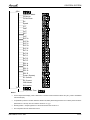
Multi Split Cinco DCI
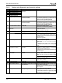
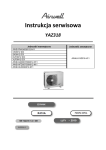
Indoor Units
Image
Wall mounted
Type
Ducted
Low
Silhouette
Floor /
Ceiling
Cassette
Outdoor Units
Model
Model
PNX 009
PNX 012
PNX 018
PNX 021
PNX 024
HFD 007
HFD 009
HFD 012
HFD 018
HAD 007
HAD 009
HAD 012
HAD 018
HAD 021
HAD 024
XLF 009
XLF 012
CK 009
CK 012
CK 018
CK 021
CK 024
PXD 009
PXD 012
PXD 018
PXD 021
PXD 024
DLF 009
DLF 012
DLF 018
DLF 021
DLF 024
DLS 018
DLS 021
DLS 024
CINCO 100 DCI
YAZ5036-H11
REFRIGERANT
HEAT PUMP
R410A
SM CINCO 1-A.1 GB
MAY – 2010
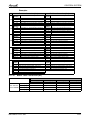
LIST OF EFFECTIVE PAGES
LIST OF EFFECTIVE PAGES
Note: Changes in the pages are indicated by a “Revision#” in the footer of each effected page
(when none indicates no changes in the relevant page). All pages in the following list represent
effected/ non effected pages divided by chapters.
Dates of issue for original and changed pages are:
Original ....... 0 ........ MAY 2010
Total number of pages in this publication is 148 consisting of the following:
Page
No.
Revision
No. #
Page
No.
Revision
No. #
Page
No.
Revision
No. #
Title ....................... 1
A ........................... 1
i ............................. 1
1-1 - 1-3 ................ 1
2-1 - 2-15 .............. 1
3-1 ........................ 1
4-1 - 4-7 ................ 1
5-1 - 5-38 .............. 1
6-1 - 6-4 ................ 1
7-1 ........................ 1
8-1 ........................ 1
9-1 - 9-2 ................ 1
10-1 ...................... 1
11-1 ....................... 1
12-1-12-41 ............ 1
13-1-13-15 ............ 1
14-1-14-6 .............. 1
15-1-15-3 .............. 1
16-1-16-5 ...............1
17-1 ...................... 1
● Zero in this column indicates an original page.
*Due to constant improvements please note that the data on this service manual can be modified
with out notice.
**Photos are not contractual
A
SM CINCO 1-A.1 GB
TABLE OF CONTENTS
Table of Contents
1.
INTRODUCTION ...................................................................................................1-1
2.
PRODUCT DATA SHEET ......................................................................................2-1
3.
RATING CONDITIONS ..........................................................................................3-1
4.
OUTLINE DIMENSIONS .......................................................................................4-1
5.
PERFORMANCE DATA ........................................................................................5-1
6.
PRESSURE CURVES ...........................................................................................6-1
7.
SOUND LEVEL CHARACTERISTICS ..................................................................7-1
8.
ELECTRICAL DATA ..............................................................................................8-1
9.
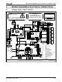
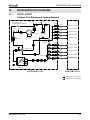
WIRING DIAGRAMS & ELECTRICAL CONNECTIONS ......................................9-1
10. REFRIGERATION DIAGRAMS .............................................................................10-1
11.
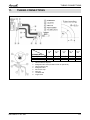
TUBING CONNECTIONS......................................................................................11-1
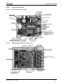
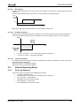
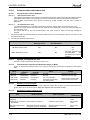
12. CONTROL SYSTEM .............................................................................................12-1
13. TROUBLESHOOTING ..........................................................................................13-1
14. SERVICING ...........................................................................................................14-1
15. EXPLODED VIEWS AND SPARE PARTS LISTS .................................................15-1
16. OPTIONAL ACCESSORIES .................................................................................16-1
17. APPENDIX A .........................................................................................................17-1
SM CINCO 1-A.1 GB
i
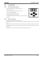
INTRODUCTION
1.
INTRODUCTION
1.1
General
The Cinco DCI Multi is a total Multi System in one unit: Duo/Trio/Quattro/Cinco.
The multi-split inverter is a high level technology product for residential and commercial application
offering comfort, low noise operation and energy saving.
1.2
Main Features
1.2.1
High Technology
1.2.2
1.3
Sine wave form in both OFAN and Compressor drives.
DC-BL-SL (DC Brush less Sensor less) Inverter Compressor.
DC-BL Inverter Outdoor fan.
Fuzzy Logic Control
System Features
Variable cooling and heating capacity from 30% to 115% (of rated caoacity).
High COP (“A” class energy rating)
Low noise levels
IAQ (Indoor Air Quality) features (LEX series)
Lego concept - Products line of wall mounted, floor/ceiling, cassette, ducted with capacity
models of 2.2, 2.5, 3.5, 5.0, 6.0 and 7.2 kW.
Networking connectivity.
Pre-charged system up to 30m.
Tubing total length up to 80m / 25m length for each indoor brench.
Tubing height difference up to 30m / 15m heigth for each indoor brench.
Dry contact inputs:
o Stand-by
o Night Mode (for silent operation in cool and heat mode)
o Power Shedding (to control maximum power consumption)
Dry contact output:
o Alarm
o Base Heater
o Crank Case Heater
Cooling operation at outdoor temperature down to -100C.
Heating operation at outdoor temperature down to -150C.
HMI Display (Human-Machine Interface) – consists of 7-segment shows both indoor and
outdoor diagnostics and setting up features.
Installation test to detect installation errors and guidance to solve them.
Monitoring softwear (PC port).
EEV (Electronic Expansion Valve) for each indoor unit.
Low and high pressure cut-off sensore for system protection.
Tubing Connections
Flare type interconnecting tubing to be produced on site.
For further details please refer to APPENDIX A on this manual, and to the relevant indoor
service Manual.
SM CINCO 1-A.1 GB
1-1
INTRODUCTION
1.4
Inbox Documentation
Outdoor unit is supplied with its installation manual and flare type adaptor connectors.
Each indoor unit is supplied with its own installation and operation manuals.
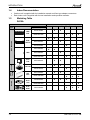
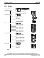
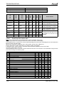
1.5
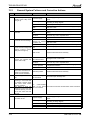
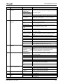
Matching Table
R410A
Indoor unit
Type
Indoor Unit Capacity [kW] (kBtu/h)
Dimensions
(W x D x H) mm
Model
LEX/
PNX
Wall- Mounted
2.5 (9) 3.5 (12) 5.0 (18) 6.0 (21) 7.0 (24)
♦
810x210x285
♦
♦
1060x221x295
680x185x250
HFD/
DELTA
2.2 (7)
♦
Cassette
Floor /
Ceiling
SX/
PXD
Ducted
CK/ CN
♦
1-2
570x160x570
♦
♦
575x575x219
♦
♦
DLS/
DNG
♦
♦
♦
♦
♦
♦
♦
♦
♦
♦
♦
1200x190x630
750x629x200
♦
♦
575x575x270
DLF/
LSN
♦
♦
840x188x250
820x190x630
♦
♦
1060x210x295
XLF/
TOP
♦
♦
900x205x295
HAD
♦
♦
840x185x250
676x188x250
♦
♦
♦
♦
1050x629x200
790x749x256
♦
SM CINCO 1-A.1 GB
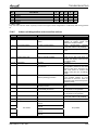
INTRODUCTION
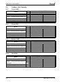
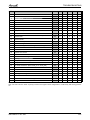
1.6
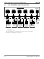
Indoor Unit combinations
Unit D
Unit E
Unit A/B
Unit C
Unit D
Unit E
Unit A
Unit B
Unit C
Unit D
Unit E
Cinco
Unit A/B/C
Quattro
Unit E
Trio
Unit D
Duo
18
18
7
7
21
7
7
7
12
7
7
7
7
7
18
21
7
7
24
7
7
7
18
7
7
7
7
9
18
24
7
9
21
7
7
7
21
7
7
7
7
12
21
21
7
9
24
7
7
7
24
7
7
7
7
18
21
24
7
12
18
7
7
9
12
7
7
7
9
9
24
24
7
12
21
7
7
9
18
7
7
7
9
12
7
12
24
7
7
9
21
7
7
7
9
18
7
18
18
7
7
9
24
7
7
7
12
12
7
18
21
7
7
12
12
7
7
9
9
9
7
18
24
7
7
12
18
7
7
9
9
12
9
9
18
7
7
12
21
7
7
9
12
12
9
9
21
7
7
18
18
7
9
9
9
9
9
9
24
7
9
9
12
7
9
9
9
12
9
12
18
7
9
9
18
7
9
9
12
12
9
12
21
7
9
9
21
9
9
9
9
9
9
12
24
7
9
9
24
9
9
9
9
12
9
18
18
7
9
12
12
9
9
9
9
18
9
18
21
7
9
12
18
9
9
9
12
12
9
18
24
7
9
12
21
9
21
21
9
9
9
9
12
12
12
9
9
9
12
12
12
18
9
9
9
18
12
12
21
9
9
9
21
12
12
24
9
9
9
24
12
18
18
9
9
12
12
12
18
21
9
9
12
18
9
9
12
21
9
9
18
18
9
12
12
12
9
12
12
18
12
12
12
12
SM CINCO 1-A.1 GB
1-3
PRODUCT DATA SHEET
2.
PRODUCT DATA SHEET
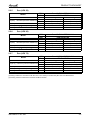
2.1
Outdoor Unit Specifications.
Model
Operation Mode
Starting Current
Circuit Breaker Current
Power Supply
Cinco 100 DCI / YAZ5036-H11
Cooling
< 10
25
220-240V/ 1PH / 50Hz
INDOOR
A
A
V/Ph/Hz
See DCI Single
Electronic expansion valve
Refrigerant control
Compressor type
Twin Rotary DC Inverter
Model
Sanyo C-7RVN153HOW
Protection device
Outdoor SW control, HPS, LPS
Heat exchanger
Hydrophilic corrugated fins ,Grooved tubes
OUTDOOR
Fan x No.
Propeller x 2
Airflow
Motor output
Pressure
Sound level (1)
Power
Dimensions
4,150
W
2 x 50
dB(A)
57
59
68
69
mm
Kg
80
WxDxH
mm
985 x 1020 x 435
Kg
85
Units per pallet
Units
6
Stacking height
Units
2
Refrigerant Charge (Precharged)
g (m)
3,000 (30m)
g
400
Liquid
mm
5 x 6.35
Suction
mm
3x 9.53 + 2x 12.7
Package
Packaged Weight
Additional charge (30-80m)
Tube size
O.D.
TUBING
m3/hr
WxDxH
Weight
Indoor & outdoor
Connection
method
between the
indoor and
outdoor units
Height difference between indoor
units
Max.15m
Height difference between indoor &
outdoor
Max.15m
Max.25m for one unit and 80m total
LCD Remote Control
Operation control type
Heating elements
Others
900 x 970 x 340
Flared
Tubing length
(1)
Heating
kW
BH 70W (Optional)
Notes:
Sound pressure level measured at 1 meter distance from unit at nominal (cool/heat) conditions.
SM CINCO 1-A.1 GB
2-1
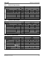
PRODUCT DATA SHEET
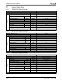
2.2
Outdoor Unit Capacity
2.2.1
Cinco (HAD)
Model
Operation Mode
Capacity (2) Nominal (minimum–Maximum)
Total Input
E.E.R (Cooling) / C.O.P (Heating)
Running Current (3)
2.2.2
ODU
IDU
Cooling
Btu/hr 32,400 (13,650 -34,800)
kW
9.5 (4.0-10.2)
W
2,940 (780-3,500)
W/W
3.05
A
13.0
ODU
IDU
Cinco 100 DCI / YAZ5036-H11
LEX 25+ LEX 25+ LEX 25 + LEX 25+ LEX 25
Btu/hr
kW
W
W/W
A
Cooling
34,120 (14,710-37,530)
10.0(4.3-11.0)
2,940 (780-3,500)
3.15
13.0
Operation Mode
Capacity (2) Nominal (minimum–Maximum)
Total Input
E.E.R (Cooling) / C.O.P (Heating)
Running Current (3)
ODU
IDU
Operation Mode
Capacity (2) Nominal (minimum–Maximum)
Total Input
E.E.R (Cooling) / C.O.P (Heating)
Running Current (3)
Btu/hr
kW
W
W/W
A
Quattro 100 DCI / YAZ5036-H11
LEX 25+LEX 25+LEX 25 +LEX 25
Cooling
30,030 (11,600-33,440)
8.8 (3.4-9.8)
2,330 (810-2,670)
3.77
10.4
Heating
34,120 (11,600-35,830)
10.0 (3.4-10.5)
2,080 (810-2,670)
4.63
9.25
Trio (LEX)
Model
ODU
IDU
Operation Mode
Capacity (2) Nominal (minimum–Maximum)
Total Input
E.E.R (Cooling) / C.O.P (Heating)
Running Current (3)
2-2
Heating
40,940 (14,710-42,650)
12.0 (4.3-12.5)
2,940 (780-3,500)
4.20
13.0
Quattro (LEX)
Model
2.2.4
Heating
38,560 (13,650-37,530)
11.3 (4.0-11.5)
2,940 (780-3,500)
3.80
13.0
Cinco (LEX)
Model
2.2.3
Cinco 100 DCI / YAZ5036-H11
HAD 22+ HAD 22+ HAD 22 + HAD 22+ HAD 22
Btu/hr
kW
W
W/W
A
Trio 100 DCI / YAZ5036-H11
LEX 35+LEX 35+LEX 35
Cooling
29,000 (10,240-32,410)
8.5 (3.0-9.5)
2,510 (720-2,910)
3.38
11.2
Heating
35,480 (10,240-38,810)
10.4 (3.0-11.4)
2,390 (720-2,910)
4.35
10.6
SM CINCO 1-A.1 GB
PRODUCT DATA SHEET
2.2.5
Duo (LEX 50)
Model
ODU
IDU
Operation Mode
Capacity (2) Nominal (minimum–Maximum)
Total Input
E.E.R (Cooling) / C.O.P (Heating)
Running Current (3)
2.2.6
Btu/hr
kW
W
W/W
A
Cooling
30,710(9,030-37,530)
9.0 (2.6-11.0)
3,000 (590-3,160)
3.0
13.3
Heating
35,960 (9,030-39,240)
10.0 (2.6-11.5)
2,940 (590-3,160)
3.58
13.1
Duo (LEX 60)
Model
ODU
IDU
Operation Mode
Capacity (2) Nominal (minimum–Maximum)
Total Input
E.E.R (Cooling) / C.O.P (Heating)
Running Current (3)
2.2.7
Duo 100 DCI / YAZ5036-H11
LEX 50 +LEX 50
Btu/hr
kW
W
W/W
A
Duo 100 DCI / YAZ5036-H11
LEX 60+LEX 60
Cooling
31,560 (9,630-37,530)
9.3 (2.8-11.0)
3,170 (550-3,200)
2.92
14.05
Heating
36,370 (9,630-40,090)
10.7 (2.8-11.8)
3,020 (550-3,200)
3.53
13.4
Duo (LEX 72)
Model
ODU
IDU
Operation Mode
Capacity (2) Nominal (minimum–Maximum)
Total Input
E.E.R (Cooling) / C.O.P (Heating)
Running Current (3)
Btu/hr
kW
W
W/W
A
Duo 100 DCI / YAZ5036-H11
LEX 72+LEX 72
Cooling
32,410 (10,240-37,530)
9.5 (3.0-11.0)
3,330 (550-3,400)
2.85
14.8
Heating
36,780 (10,240-40,940)
10.8 (3.0-12.0)
3,090 (550-3,440)
3.49
13.7
Notes:
(2) Rating conditions in accordance with ISO 5151, ISO 13253 (for ducted units) EN 14511 and EUROVENT.
(3) Running Current is measured in nominal conditions at 230V
SM CINCO 1-A.1 GB
2-3
PRODUCT DATA SHEET
2.3
Indoor Units Data
2.3.1
PNX009 DCI Specifications
Model Indoor Unit
INDOOR
Installation Method of Pipe
Power supply
Fan type & quantity
Fan speeds
Air flow(1)
External static pressure
Sound power level(2)
Sound pressure level(3)
Moisture removal
Condenstate drain tube I.D
Dimensions
Net Weight
Package dimensions
Packaged weight
Units per pallet
Stacking height
2.3.2
PNX009 DCI
V/Ph/Hz
H/M/L
H/M/L
Min
H/M/L
H/M/L
WxHxD
WxHxD
RPM
m3/hr
Pa
dB(A)
dB(A)
l/hr
mm
mm
kg
mm
kg
units
units
PNX012 DCI Specifications
Model Indoor Unit
INDOOR
Installation Method of Pipe
Power supply
Fan type & quantity
Fan speeds
Air flow(1)
External static pressure
Sound power level(2)
Sound pressure level(3)
Moisture removal
Condenstate drain tube I.D
Dimensions
Net Weight
Package dimensions
Packaged weight
Units per pallet
Stacking height
2.3.3
PNX012 DCI
V/Ph/Hz
H/M/L
H/M/L
Min
H/M/L
H/M/L
WxHxD
WxHxD
RPM
m3/hr
Pa
dB(A)
dB(A)
l/hr
mm
mm
kg
mm
kg
units
units
Installation Method of Pipe
Power supply
Fan type & quantity
Fan speeds
Air flow(1)
External static pressure
Sound power level(2)
Sound pressure level(3)
Moisture removal
Condenstate drain tube I.D
Dimensions
Net Weight
Package dimensions
Packaged weight
Units per pallet
Stacking height
INDOOR
Flared
220-230V/1 Ph/50 Hz
Crossflow x 1
1100/950/800
550/450/350
0
52/ - /39
40/ - /26
1.5
16
810x285x210
11.5
870x356x282
14
28
7 levels
PNX018 DCI Specifications
Model Indoor Unit
2-4
Flared
220-230V/1 Ph/50 Hz
Crossflow x 1
1050/900/800
530/430/330
0
51/ - /39
39/ - /26
1
16
810x285x210
11.5
870x356x282
14
28
7 levels
PNX018 DCI
V/Ph/Hz
H/M/L
H/M/L
Min
H/M/L
H/M/L
WxHxD
WxHxD
RPM
m3/hr
Pa
dB(A)
dB(A)
l/hr
mm
mm
kg
mm
kg
units
units
Flared
220-230V/1 Ph/50 Hz
Crossflow x 1
1200/1050/900
850/700/550
0
55/51/47
43/39/34
2
16
1060x295x221
15
1125x360x295
18
16
8 levels
SM CINCO 1-A.1 GB
PRODUCT DATA SHEET
2.3.4
PNX021 DCI Specifications
INDOOR
Model Indoor Unit / Type
Installation Method of pipe
Power Supply
Fan Type & Quantity
Fan speed
Airflow(2)
External static pressure
Sound Power Level(3)
Sound Pressure Level (4)
Moisture removal
Condensate Drain Tube I.D.
Dimensions
Weight
Package Dimensions
Packeged wight
Units per pallet
Stacking Height
2.3.5
V/Ph/Hz
H/M/L
H/M/L
Min-Nom-Max
H/M/L
H/M/L
W/H/D
W/H/D
RPM
m3/hr
Pa
dB (A)
dB (A)
l/h
mm
mm
kg
mm
Kg
PNX021 DCI / Wall Mounted
FLARE
1250
900
56
45
1060
1125
Units
220-240 / 1/ 50
Crossflow *1
1100
760
53
40
2.0
16
295
15
360
18
16
8
1000
620
48
34
221
295
PNX024 DCI Specifications
INDOOR
Model Indoor Unit / Type
Installation Method of pipe
Power Supply
Fan Type & Quantity
Fan speed
Airflow(2)
External static pressure
Sound Power Level(3)
Sound Pressure Level (4)
Moisture removal
Condensate Drain Tube I.D.
Dimensions
Weight
Package Dimensions
Packeged wight
Units per pallet
Stacking Height
PNX024 DCI / Wall Mounted
V/Ph/Hz
H/M/L
H/M/L
Min-Nom-Max
H/M/L
H/M/L
W/H/D
W/H/D
RPM
m3/hr
Pa
dB (A)
dB (A)
l/h
mm
mm
kg
mm
Kg
1300
950
60
47
1060
1125
Units
FLARE
220-240 / 1/ 50
Crossflow *1
1150
800
54
41
2.5
16
295
15
360
18
16
8
1000
650
47
34
221
295
2.3.6 HFD007 DCI Specifications
INDOOR
Model Indoor Unit / Type
Installation Method of pipe
Power Supply
Fan Type & Quantity
Fan speed
Airflow(2)
External static pressure
Sound Power Level(3)
Sound Pressure Level (4)
Moisture removal
Condensate Drain Tube I.D.
Dimensions
Weight
Package Dimensions
Packeged wight
Units per pallet
Stacking Height
SM CINCO 1-A.1 GB
HFD007 DCI / Wall Mounted
V/Ph/Hz
H/M/L
H/M/L
Min-Nom-Max
H/M/L
H/M/L
W/H/D
W/H/D
RPM
m3/hr
Pa
dB (A)
dB (A)
l/h
mm
mm
kg
mm
Kg
Units
1100
400
49
36
680
740
FLARE
220-240 / 1/ 50
Crossflow x1
950
350
46
33
1.0
16
250
7
265
10
36
9
800
300
43
30
185
320
2-5
PRODUCT DATA SHEET
2.3.7
HFD009 DCI Specifications
Model Indoor Unit
INDOOR
Installation Method of Pipe
Power supply
Fan type & quantity
Fan speeds
Air flow(1)
External static pressure
Sound power level(2)
Sound pressure level(3)
Moisture removal
Condenstate drain tube I.D
Dimensions
Net Weight
Package dimensions
Packaged weight
Units per pallet
Stacking height
2.3.8
HFD009 DCI
V/Ph/Hz
H/M/L
H/M/L
Min
H/M/L
H/M/L
WxHxD
WxHxD
RPM
m3/hr
Pa
dB(A)
dB(A)
l/hr
mm
mm
kg
mm
kg
units
units
HFD012 DCI Specifications
Model Indoor Unit
INDOOR
Installation Method of Pipe
Power supply
Fan type & quantity
Fan speeds
Air flow(1)
External static pressure
Sound power level(2)
Sound pressure level(3)
Moisture removal
Condenstate drain tube I.D
Dimensions
Net Weight
Package dimensions
Packaged weight
Units per pallet
Stacking height
2.3.9
HFD012 DCI
V/Ph/Hz
H/M/L
H/M/L
Min
H/M/L
H/M/L
WxHxD
WxHxD
RPM
m3/hr
Pa
dB(A)
dB(A)
l/hr
mm
mm
kg
mm
kg
units
units
Installation Method of Pipe
Power supply
Fan type & quantity
Fan speeds
Air flow(1)
External static pressure
Sound power level(2)
Sound pressure level(3)
Moisture removal
Condenstate drain tube I.D
Dimensions
Net Weight
Package dimensions
Packaged weight
Units per pallet
Stacking height
INDOOR
Flared
220-240/1/50
Crossflow x 1
1200/1000/850
550/450/350
0
56/50/46
39/33/29
1.5
16
840x250x185
8
930x320x265
11
36 units per pallet
9 levels
HFD018 DCI Specifications
Model Indoor Unit
2-6
Flared
220-240/1/50
Crossflow x 1
1200/1050/850
420/350/270
0
54/50/47
39/35/32
1
16
680x250x185
7
740x320x265
10
36 units per pallet
9 levels
HFD018 DCI
V/Ph/Hz
H/M/L
H/M/L
Min
H/M/L
H/M/L
WxHxD
WxHxD
RPM
m3/hr
Pa
dB(A)
dB(A)
l/hr
mm
mm
kg
mm
kg
units
units
Flared
220-240/1/50
Crossflow x 1
1230/1100/900
720/620/480
0
56/54/47
44/41/34
2
16
900x295x205
11
960x360x270
14
24 units per pallet
8 levels
SM CINCO 1-A.1 GB
PRODUCT DATA SHEET
2.3.10
HAD007 DCI Specifications
Model Indoor Unit / Type
INDOOR
Installation Method of pipe
Power Supply
Fan Type & Quantity
Fan speed
Airflow(2)
External static pressure
Sound Power Level(3)
Sound Pressure Level (4)
Moisture removal
Condensate Drain Tube I.D.
Dimensions
Weight
Package Dimensions
Packeged wight
Units per pallet
Stacking Height
2.3.11
HAD007 DCI / Wall Mounted
V/Ph/Hz
H/M/L
H/M/L
Min-Nom-Max
H/M/L
H/M/L
W/H/D
W/H/D
RPM
m3/hr
Pa
dB (A)
dB (A)
l/h
mm
mm
kg
mm
Kg
Units
49
36
680
740
800
300
43
30
185
320
HAD009 DCI Specifications
Model Indoor Unit
INDOOR
Installation Method of Pipe
Power supply
Fan type & quantity
Fan speeds
Air flow(1)
External static pressure
Sound power level(2)
Sound pressure level(3)
Moisture removal
Condenstate drain tube I.D
Dimensions
Net Weight
Package dimensions
Packaged weight
Units per pallet
Stacking height
2.3.12
1100
400
FLARE
220-240 / 1/ 50
Crossflow x1
950
350
46
33
0.9
16
250
7
265
10
36
9
HAD009 DCI
V/Ph/Hz
H/M/L
H/M/L
Min
H/M/L
H/M/L
WxHxD
WxHxD
RPM
m3/hr
Pa
dB(A)
dB(A)
l/hr
mm
mm
kg
mm
kg
units
units
Flared
220-240/1/50
Crossflow x 1
1150/1000/800
420/350/270
0
54
40/35/29
1.0
16
680 x250 X188
7
740x310x248
10
32
8
HAD012 DCI Specifications
Model Indoor Unit
INDOOR
Installation Method of Pipe
Power supply
Fan type & quantity
Fan speeds
Air flow(1)
External static pressure
Sound power level(2)
Sound pressure level(3)
Moisture removal
Condenstate drain tube I.D
Dimensions
Net Weight
Package dimensions
Packaged weight
Units per pallet
Stacking height
SM CINCO 1-A.1 GB
HAD012 DCI
V/Ph/Hz
H/M/L
H/M/L
Min
H/M/L
H/M/L
WxHxD
WxHxD
RPM
m3/hr
Pa
dB(A)
dB(A)
l/hr
mm
mm
kg
mm
kg
units
units
Flared
220-240/1/50
Crossflow x 1
1150/950/750
550/450/350
0
56
40/34/28
1.5
16
840x250x188
8
900x310x248
11
32
8
2-7
PRODUCT DATA SHEET
2.3.13
HAD021 DCI Specifications
INDOOR
Model Indoor Unit / Type
Installation Method of pipe
Power Supply
Fan Type & Quantity
Fan speed
Airflow(2)
External static pressure
Sound Power Level(3)
Sound Pressure Level (4)
Moisture removal
Condensate Drain Tube I.D.
Dimensions
Weight
Package Dimensions
Packeged wight
Units per pallet
Stacking Height
2.3.14
V/Ph/Hz
H/M/L
H/M/L
Min-Nom-Max
H/M/L
H/M/L
W/H/D
W/H/D
RPM
m3/hr
Pa
dB (A)
dB (A)
l/h
mm
mm
kg
mm
Kg
1060
1125
1000
620
48
34
221
295
INDOOR
HAD024 DCI / Wall Mounted
V/Ph/Hz
H/M/L
H/M/L
Min-Nom-Max
H/M/L
H/M/L
W/H/D
W/H/D
RPM
m3/hr
Pa
dB (A)
dB (A)
l/h
mm
mm
kg
mm
Kg
1300
950
60
47
1060
1125
FLARE
220-240 / 1/ 50
Crossflow *1
1150
800
54
41
2.5
16
295
15
360
18
16
1000
650
47
34
221
295
XLF009 DCI Specifications
Installation Method of Pipe
Power supply
Fan type & quantity
Fan speeds
Air flow(1)
External static pressure
Sound power level(2)
Sound pressure level(3)
Moisture removal
Condenstate drain tube I.D
Dimensions
Net Weight
Package dimensions
Packaged weight
Units per pallet
Stacking height
INDOOR
56
45
Units
Model Indoor Unit
2-8
1250
900
FLARE
220-240 / 1/ 50
Crossflow *1
1100
760
53
40
2.0
16
295
15
360
18
16
8
HAD024 DCI Specifications
Model Indoor Unit / Type
Installation Method of pipe
Power Supply
Fan Type & Quantity
Fan speed
Airflow(2)
External static pressure
Sound Power Level(3)
Sound Pressure Level (4)
Moisture removal
Condensate Drain Tube I.D.
Dimensions
Weight
Package Dimensions
Packeged wight
Units per pallet
2.3.15
HAD021 DCI / Wall Mounted
XLF009 DCI
V/Ph/Hz
H/M/L
H/M/L
Min
H/M/L
H/M/L
WxHxD
WxHxD
RPM
m3/hr
Pa
dB(A)
dB(A)
l/hr
mm
mm
kg
mm
kg
units
units
Flared
220-240/1/50
Helicoid x 1
520/490/450
390/370/330
0
55
38/35/32
1
16
570x570x160
13.5
700x700x255
15.5
16
8levels
SM CINCO 1-A.1 GB
PRODUCT DATA SHEET
2.3.16
XLF012 DCI Specifications
Model Indoor Unit
INDOOR
Installation Method of Pipe
Power supply
Fan type & quantity
Fan speeds
Air flow(1)
External static pressure
Sound power level(2)
Sound pressure level(3)
Moisture removal
Condenstate drain tube I.D
Dimensions
Net Weight
Package dimensions
Packaged weight
Units per pallet
Stacking height
2.3.17
XLF012 DCI
V/Ph/Hz
H/M/L
H/M/L
Min
H/M/L
H/M/L
RPM
m3/hr
Pa
dB(A)
dB(A)
l/hr
mm
mm
kg
mm
kg
units
units
WxHxD
WxHxD
CK009 DCI Specifications
Model Indoor Unit
INDOOR
Installation Method of Pipe
Power supply
Fan type & quantity
Fan speeds
Air flow(1)
External static pressure
Sound power level(2)
Sound pressure level(3)
Moisture removal
Condenstate drain tube I.D
Dimensions
Net Weight
Package dimensions
Packaged weight
Units per pallet
Stacking height
2.3.18
Flared
220-240/1/50
Helicoid x 1
540/510/450
400/370/310
0
56
39/36/33
1.6
16
570x570x160
14
700x700x255
16
16
8evels
CK009 DCI
V/Ph/Hz
H/M/L
H/M/L
Min
H/M/L
H/M/L
WxHxD
WxHxD
RPM
m3/hr
Pa
dB(A)
dB(A)
l/hr
mm
mm
kg
mm
kg
units
units
Flared
220-230V/1 Ph/50 Hz
Centrifugal x 1
550/500/450
600/520/450
420/370/320
470/390/320
0
49
49
32/30/28
34/31/28
0.7
20
575X575X219(625X625X40/725X725X40)
12.9(2.2/2.7)
681X681X297(700X700X103/800X800X103)
16.2(3.4/4.2)
12
6 levels
CK012 DCI Specifications
Model Indoor Unit
INDOOR
Installation Method of Pipe
Power supply
Fan type & quantity
Fan speeds
Air flow(1)
External static pressure
Sound power level(2)
Sound pressure level(3)
Moisture removal
Condenstate drain tube I.D
Dimensions
Net Weight
Package dimensions
Packaged weight
Units per pallet
Stacking height
SM CINCO 1-A.1 GB
CK012 DCI
V/Ph/Hz
H/M/L
H/M/L
Min
H/M/L
H/M/L
WxHxD
WxHxD
RPM
m3/hr
Pa
dB(A)
dB(A)
l/hr
mm
mm
kg
mm
kg
units
units
Flared
220-230V/1 Ph/50 Hz
Centrifugal x 1
600/520/450
650/550/450
470/390/320
510/420//320
0
51
51
34/31/28
36/32/28
1.5
20
575X575X219(625X625X40/725X725X40)
12.9(2.2/2.7)
681X681X297(700X700X103/800X800X103)
16.2(3.4/4.2)
12
6 levels
2-9
PRODUCT DATA SHEET
2.3.19
CK018 DCI Specifications
Model Indoor Unit
INDOOR
Installation Method of Pipe
Power supply
Fan type & quantity
Fan speeds
Air flow(1)
External static pressure
Sound power level(2)
Sound pressure level(3)
Moisture removal
Condenstate drain tube I.D
Dimensions
Net Weight
Package dimensions
Packaged weight
Units per pallet
Stacking height
2.3.20
INDOOR
INDOOR
H/M/L
H/M/L
Min
H/M/L
H/M/L
WxHxD
WxHxD
RPM
m3/hr
Pa
dB(A)
dB(A)
l/hr
mm
mm
kg
mm
kg
units
units
Flared
220-230V/1 Ph/50 Hz
Centrifugal x 1
680/620/550
680/620/550
620/560/500
620/560/500
0
54
54
36/33/30
36/33/30
2.0
20
575X575X270(625X625X40/725X725X40)
15.2(2.2/2.7)
681X681X348(700X700X103/800X800X103)
18.7(3.4/4.2)
12
6 levels
CK021 DCI / Cassette
Cool
V/Ph/Hz
H/M/L
H/M/L
Min-Nom-Max
H/M/L
H/M/L
W/H/D
W/H/D
RPM
m3/hr
Pa
dB (A)
dB (A)
l/h
mm
mm
kg
mm
Kg
Units
Heat
FLARE
220-240 / 1/ 50
Centrifulgal *1
800 / 710 / 600
800 / 700 / 600
800
800
58
58
41 / 33
41 / 33
2.6
20
575x575x219 (625x625x40 / 725x725x40
15.2 (2.2 / 2.7)
681x681x297 (700x700x103 / 800x800x103
17.7 (3.4 / 4.2)
12
6
CK024 DCI Specifications
Model Indoor Unit / Type
Operation Mode
Installation Method of pipe
Power Supply
Fan Type & Quantity
Fan speed
Airflow(2)
External static pressure
Sound Power Level(3)
Sound Pressure Level (4)
Moisture removal
Condensate Drain Tube I.D.
Dimensions
Weight
Package Dimensions
Packeged wight
Units per pallet
Stacking Height
2-10
V/Ph/Hz
CK021 DCI Specifications
Model Indoor Unit / Type
Operation Mode
Installation Method of pipe
Power Supply
Fan Type & Quantity
Fan speed
Airflow(2)
External static pressure
Sound Power Level(3)
Sound Pressure Level (4)
Moisture removal
Condensate Drain Tube I.D.
Dimensions
Weight
Package Dimensions
Packeged wight
Units per pallet
Stacking Height
2.3.21
CK018 DCI
CK024 DCI / Cassette
Cool
V/Ph/Hz
H/M/L
H/M/L
Min-Nom-Max
H/M/L
H/M/L
W/H/D
W/H/D
RPM
m3/hr
Pa
dB (A)
dB (A)
l/h
mm
mm
kg
mm
Kg
Units
Heat
FLARE
220-240 / 1/ 50
Centrifulgal *1
850 / 750 / 650
850 / 750 / 650
830
830
60
60
43 / 35
43 / 35
2.6
20
575x575x219 (625x625x40 / 725x725x40
15.2 (2.2 / 2.7)
681x681x297 (700x700x103 / 800x800x103
18.7 (3.4 / 4.2)
12
6
SM CINCO 1-A.1 GB
PRODUCT DATA SHEET
2.3.22
SX009 DCI Specifications
Model Indoor Unit
INDOOR
Installation Method of Pipe
Power supply
Fan type & quantity
Fan speeds
Air flow(1)
External static pressure
Sound power level(2)
Sound pressure level(3)
Moisture removal
Condenstate drain tube I.D
Dimensions
Net Weight
Package dimensions
Package weight
Units per pallet
Units stacking
2.3.23
SX009 DCI
V/Ph/Hz
H/M/L
H/M/L
Min
H/M/L
H/M/L
WxHxD
WxHxD
RPM
m3/hr
Pa
dB(A)
dB(A)
l/hr
mm
mm
kg
mm
kg
units
units
SX012 DCI Specifications
Model Indoor Unit
INDOOR
Installation Method of Pipe
Power supply
Fan type & quantity
Fan speeds
Air flow(1)
External static pressure
Sound power level(2)
Sound pressure level(3)
Moisture removal
Condenstate drain tube I.D
Dimensions
Net Weight
Package dimensions
Package weight
Units per pallet
Units stacking
2.3.24
Flared
220-240/1/50
Centifugal x 2
760/670/500
400/350/300
0
54/49/41
42/37/29
1
16
820x630x190
21
920x726x273
25
14units per pallet
7 levels
SX012 DCI
V/Ph/Hz
H/M/L
H/M/L
Min
H/M/L
H/M/L
WxHxD
WxHxD
RPM
m3/hr
Pa
dB(A)
dB(A)
l/hr
mm
mm
kg
mm
kg
units
units
Flared
220-240/1/50
Centifugal x 2
830/760/500
450/400/300
0
56/53/41
45/41/30
1.5
16
820x630x190
22
920x726x273
26
14units per pallet
7 levels
SX018 DCI Specifications
Model Indoor Unit
INDOOR
Installation Method of Pipe
Power supply
Fan type & quantity
Fan speeds
Air flow(1)
External static pressure
Sound power level(2)
Sound pressure level(3)
Moisture removal
Condenstate drain tube I.D
Dimensions
Net Weight
Package dimensions
Package weight
Units per pallet
Units stacking
SM CINCO 1-A.1 GB
SX018 DCI
V/Ph/Hz
H/M/L
H/M/L
Min
H/M/L
H/M/L
WxHxD
WxHxD
RPM
m3/hr
Pa
dB(A)
dB(A)
l/hr
mm
mm
kg
mm
kg
units
units
Flared
220-240/1/50
Centifugal x 2
1050/950/700
870/750/600
0
65/60/53
51/48/40
2
16
1200x630x190
30
1300x726x273
35
7units per pallet
7 levels
2-11
PRODUCT DATA SHEET
2.3.25
SX021 DCI Specifications
INDOOR
Model Indoor Unit / Type
Installation Method of pipe
Power Supply
Fan Type & Quantity
Fan speed
Airflow(2)
External static pressure
Sound Power Level(3)
Sound Pressure Level (4)
Moisture removal
Condensate Drain Tube I.D.
Dimensions
Weight
Package Dimensions
Packeged wight
Units per pallet
Stacking Height
2.3.26
V/Ph/Hz
H/M/L
H/M/L
Min-Nom-Max
H/M/L
H/M/L
W/H/D
W/H/D
RPM
m3/hr
Pa
dB (A)
dB (A)
l/h
mm
mm
kg
mm
Kg
1300
1050
760
190
273
INDOOR
SX024 DCI / Floor-Ceiling
V/Ph/Hz
H/M/L
H/M/L
Min-Nom-Max
H/M/L
H/M/L
W/H/D
W/H/D
RPM
m3/hr
Pa
dB (A)
dB (A)
l/h
mm
mm
kg
mm
Kg
Units
1300
1020
1200
1300
FLARE
220-240 / 1/ 50
Centrifugal x2
1200
930
67 / 64 / 60
56 / 53 / 49
2.5
16
630
32
726
36
7
7
1050
760
190
273
DLF009 DCI Specifications
Installation Method of Pipe
Power supply
Fan type & quantity
Fan speeds
Air flow(1)
External static pressure
Sound power level(2)
Sound pressure level(3)
Moisture removal
Condenstate drain tube I.D
Dimensions
Net Weight
Package dimensions
Package weight
Units per pallet
Units stacking
INDOOR
1200
Units
Model Indoor Unit
2-12
1300
1020
FLARE
220-240 / 1/ 50
Centrifugal x2
1200
930
67 / 64 / 60
56 / 53 / 49
2.5
16
630
32
726
36
7
7
SX024 DCI Specifications
Model Indoor Unit / Type
Installation Method of pipe
Power Supply
Fan Type & Quantity
Fan speed
Airflow(2)
External static pressure
Sound Power Level(3)
Sound Pressure Level (4)
Moisture removal
Condensate Drain Tube I.D.
Dimensions
Weight
Package Dimensions
Packeged wight
Units per pallet
Stacking Height
2.3.27
SX012 DCI / Floor-Ceiling
DLF009 DCI
V/Ph/Hz
H/M/L
H/M/L
Min -Max
H/M/L
H/M/L
WxHxD
WxHxD
RPM
m3/hr
Pa
dB(A)
dB(A)
l/hr
mm
mm
kg
mm
kg
units
units
DUCTED
220-240/1/50
Centifugal x 2
920/810/740
620/560/490
0-30
50/47/44
29/26/23
0.5
19
750x630x200
20
885x695x226
23
14units per pallet
7 levels
SM CINCO 1-A.1 GB
PRODUCT DATA SHEET
2.3.28
DLF012 DCI Specifications
Model Indoor Unit
INDOOR
Installation Method of Pipe
Power supply
Fan type & quantity
Fan speeds
Air flow(1)
External static pressure
Sound power level(2)
Sound pressure level(3)
Moisture removal
Condenstate drain tube I.D
Dimensions
Net Weight
Package dimensions
Package weight
Units per pallet
Units stacking
2.3.29
DLF012 DCI
DUCTED
220-240/1/50
Centifugal x 2
980/860/730
650/580/490
0-30
53/49/45
31/27/24
1.0
19
750x630x200
20
885x695x226
23
14units per pallet
7 levels
V/Ph/Hz
H/M/L
H/M/L
Min-Max
H/M/L
H/M/L
WxHxD
WxHxD
RPM
m3/hr
Pa
dB(A)
dB(A)
l/hr
mm
mm
kg
mm
kg
units
units
DLF018 DCI Specifications
Model Indoor Unit
INDOOR
Installation Method of Pipe
Power supply
Fan type & quantity
Fan speeds
Air flow(1)
External static pressure
Sound power level(2)
Sound pressure level(3)
Moisture removal
Condenstate drain tube I.D
Dimensions
Net Weight
Package dimensions
Package weight
Units per pallet
Units stacking
2.3.30
DLF018 DCI
DUCTED
220-240/1/50
Centifugal x 2
1100/980/860
710/600/540
0-40
54/51/48
35/32/29
1.5
19
750x630x200
21
885x695x226
24
14units per pallet
7 levels
V/Ph/Hz
H/M/L
H/M/L
Min-Max
H/M/L
H/M/L
WxHxD
WxHxD
RPM
m3/hr
Pa
dB(A)
dB(A)
l/hr
mm
mm
kg
mm
kg
units
units
DLF021 DCI Specifications
INDOOR
Model Indoor Unit / Type
Installation Method of pipe
Power Supply
Fan Type & Quantity
Fan speed
Airflow(2)
External static pressure
Sound Power Level(3)
Sound Pressure Level (4)
Moisture removal
Condensate Drain Tube I.D.
Dimensions
Weight
Package Dimensions
Packeged wight
Units per pallet
Stacking Height
SM CINCO 1-A.1 GB
DLF021 DCI / Low Silouhette
V/Ph/Hz
H/M/L
H/M/L
Min-Nom-Max
H/M/L
H/M/L
W/H/D
W/H/D
RPM
m3/hr
Pa
dB (A)
dB (A)
l/h
mm
mm
kg
mm
Kg
Units
1170
1100
59
38
1050
1185
FLARE
220-240 / 1/ 50
Centrifugal x2
1050
950
0-40
55
34
1.7
19
630
25
695
28
14
7
960
880
53
32
200
226
2-13
PRODUCT DATA SHEET
2.3.31
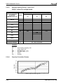
DLF024 DCI Specifications
INDOOR
Model Indoor Unit / Type
Installation Method of pipe
Power Supply
Fan Type & Quantity
Fan speed
Airflow(2)
External static pressure
Sound Power Level(3)
Sound Pressure Level (4)
Moisture removal
Condensate Drain Tube I.D.
Dimensions
Weight
Package Dimensions
Packeged wight
Units per pallet
Stacking Height
2.3.32
DLF024 DCI / Low Silouhette
V/Ph/Hz
H/M/L
H/M/L
Min-Nom-Max
H/M/L
H/M/L
W/H/D
W/H/D
RPM
m3/hr
Pa
dB (A)
dB (A)
l/h
mm
mm
kg
mm
Kg
1200
115
63
39
1050
1185
Units
INDOOR
Installation Method of Pipe
Power supply
Fan type & quantity
Fan speeds
Air flow(1)
External static pressure
Sound power level(2)
Sound pressure level(3)
Moisture removal
Condenstate drain tube I.D
Dimensions
Net Weight
Package dimensions
Packaged weight
Units per pallet
Stacking height
INDOOR
56
32
200
226
DLS018 DCI
Flared
220-240/1/50
Centrifugal x 1
630/530/425
1170/875/730
25
55/53/50
42/37/34
1.0
22
770x690x260
29
959x854x315
31
6
6
V/Ph/Hz
H/M/L
H/M/L
Min
H/M/L
H/M/L
WxHxD
WxHxD
RPM
m3/hr
Pa
dB(A)
dB(A)
l/hr
mm
mm
kg
mm
kg
units
units
DLS021 DCI Specifications
Model Indoor Unit / Type
Installation Method of pipe
Power Supply
Fan Type & Quantity
Fan speed
Airflow(2)
External static pressure
Sound Power Level(3)
Sound Pressure Level (4)
Moisture removal
Condensate Drain Tube I.D.
Dimensions
Weight
Package Dimensions
Packeged wight
Units per pallet
Stacking Height
2-14
980
900
DLS018 DCI Specifications
Model Indoor Unit
2.3.33
FLARE
220-240 / 1/ 50
Centrifugal x2
1050
950
0-40
59
35
2.0
19
630
25
695
28
14
7
DLS021 DCI / Ducted
V/Ph/Hz
H/M/L
H/M/L
Min-Nom-Max
H/M/L
H/M/L
W/H/D
W/H/D
RPM
m3/hr
Pa
dB (A)
dB (A)
l/h
mm
mm
kg
mm
Kg
Units
680
1225
790
959
FLARE
220-240 / 1/ 50
Centrifugal x1
530
875
25-70
60 / 53 / 50
43 / 37 / 34
1.2
19
749
29
854
31
6
6
425
710
256
315
SM CINCO 1-A.1 GB
PRODUCT DATA SHEET
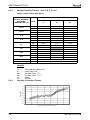
2.3.34
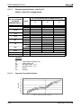
DLS024 DCI Specifications
INDOOR
Model Indoor Unit / Type
Installation Method of pipe
Power Supply
Fan Type & Quantity
Fan speed
Airflow(2)
External static pressure
Sound Power Level(3)
Sound Pressure Level (4)
Moisture removal
Condensate Drain Tube I.D.
Dimensions
Weight
Package Dimensions
Packeged wight
Units per pallet
Stacking Height
DLS024 DCI / Ducted
V/Ph/Hz
H/M/L
H/M/L
Min-Nom-Max
H/M/L
H/M/L
W/H/D
W/H/D
RPM
m3/hr
Pa
dB (A)
dB (A)
l/h
mm
mm
kg
mm
Kg
Units
800
1310
790
959
FLARE
220-240 / 1/ 50
Centrifugal x1
670
1115
25-75
65 / 60 / 55
47 / 43 / 38
1.5
19
749
29
854
31
6
6
550
890
256
315
NOTE:
Rating conditions in accordance with ISO 5151 and ISO 13253 (for ducted units) and EN14511.
(2)
Airflow in ducted units; at nominal external static pressure.
(3)
Sound power in ducted units is measured at air discharge.
(4)
Sound pressure level measured at 1 meter distance from unit.
SM CINCO 1-A.1 GB
2-15
RATING CONDITIONS
3.
RATING CONDITIONS
Standard conditions in accordance with ISO 5151, ISO 13253 (for ducted units)
and EN 14511.
Cooling:
Indoor:
27oC DB 19oC WB
Outdoor: 35 oC DB
Heating:
Indoor:
20oC DB
Outdoor: 7oC DB 6oC WB
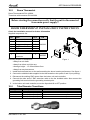
3.1
Operating Limits
Indoor
Cooling
Heating
Voltage
Outdoor
Upper limit
32oC DB 23oC WB
46oC DB
Lower limit
21oC DB 15oC WB
-10oC DB
Upper limit
27oC DB
24oC DB 18oC WB
Lower limit
10oC DB
-15oC DB -16oC WB
1PH
198 – 264 V
3PH
N/A
SM CINCO 1-A.1 GB
3-1
OUTLINE DIMENSIONS
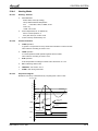
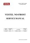
OUTLINE DIMENSIONS
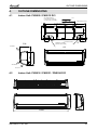
4.1
Indoor Unit: PNX009 / PNX012 DCI
MOUNTING TEMPLATE
TO BE USED FOR LOCATION
OF INDOOR UNIT ON THE WALL
CEELING
18.5
810.0
MOUTING PLATE OUTLINE
30.0
167.5
167.5
100.0 MIN
4.
INDOOR UNIT OUTLINE
83.0
83.0
42.0
42.0
100.5
100.5
285.0
8.0
8.0
93.0
70.0
TUBING WALL OPENING
(FOR REAR ROUTING)
93.0
70.0
TUBING WALL OPENING
(FOR REAR LEFT ROUTING)
210
811
285
AIR INTAKE
AIR INTAKE
AIR OUTLET
Indoor Unit: PNX018 / PNX021 / PNX024 DCI
295
4.2
1060
SM CINCO 1-A.1 GB
221
4-1
OUTLINE DIMENSIONS
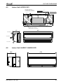
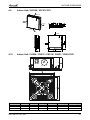
4.3
Indoor Units: HFD007 / HFD009 DCI
4.4
Indoor Unit: HFD012 DCI
4-2
SM CINCO 1-A.1 GB
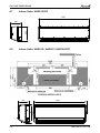
OUTLINE DIMENSIONS
Indoor Unit: HFD018 DCI
MOUNTING TEMPLATE
TO BE USED FOR LOCATION
OF INDOOR UNIT ON THE WALL
CEILING
483
203
60
Min50
4.5
INDOOR UNIT OUTLINE
42
76
295
177
60
88
225
88
440
900
TUBING WALL OPENING
(FOR REAR ROUTING)
TUBING WALL OPENING
(FOR REAR LEFT ROUTING)
205
900
AIR INTAKE
295
AIR INTAKE
AIR OUTLET
4.6
Indoor Unit: HAD007 / HAD009 DCI
676
250
188
SM CINCO 1-A.1 GB
4-3
OUTLINE DIMENSIONS
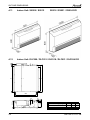
4.7
Indoor Units: HAD012 DCI
836
250
188
4.8
Indoor Units: HAD018 / HAD021 / HAD024 DCI
1060
295
219
4-4
SM CINCO 1-A.1 GB
OUTLINE DIMENSIONS
4.9
Indoor Unit: XLF009 / XLF012 DCI
AIR OUTLET
AIR OUTLET
AIR OUTLET
AIR OUTLET
AIR INTAKE
AIR INTAKE
AIR INTAKE
AIR INTAKE
4.10
Indoor Unit: CK009 / CK012 / CK018 / CK021 / CK024 DCI
Unit Model
009/012
018/021/024
Main unit A Insulation B Front Step C Front width D
219
270
SM CINCO 1-A.1 GB
2
2
9
9
625/725
625/725
Front height E
Effective Height H
40
40
230
281
4-5
OUTLINE DIMENSIONS
Indoor Unit: SX009 / SX012
SX018 / SX021 / SX024 DCI
4.12
Indoor Unit: DLF009 / DLF012 / DLF018 / DLF021 / DLF024 DCI
A
B
C
59
4.11
565
4-6
21
160
200
59
27
629 (640 With air filter)
Nominal Capacity
2.5 -5.0 kW
6.0-7.2 kW
A
B
C
750 696 790
1050 996 1090
SM CINCO 1-A.1 GB
OUTLINE DIMENSIONS
4.13
Indoor Unit: DLS018 / DLS021 / DLS024 DCI
K
L
73 80
F
G
J
I
H
36
359
E
D
61
19
A
B
C
Model
A
B
C
D
E
F
G
H
I
J
K
L
DLS018 / DLS021 / DLS024
790
653
749
758
797
256
195
702
599
684
162
242
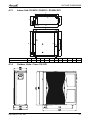
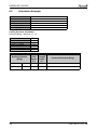
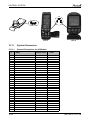
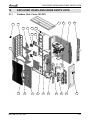
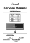
4.14
Outdoor Units: Cinco 100 DCI
SM CINCO 1-A.1 GB
4-7
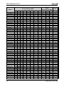
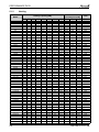
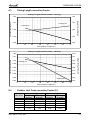
PERFORMANCE DATA
5.
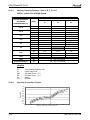
PERFORMANCE DATA
5.1
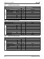
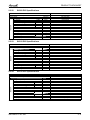
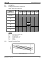
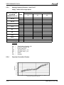
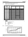
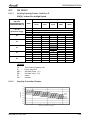
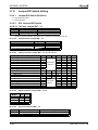
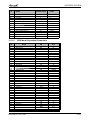
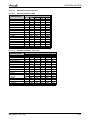
Outdoor Unit Cinco 100 DCI Combinations (Delta + LEX)
5.1.1
Cooling
Model
7
9
12
18
21
24
7+7
7+9
7+12
7+18
7+21
7+24
9+9
9+12
9+18
9+21
9+24
12+12
12+18
12+21
12+24
18+18
18+21
18+24
21+21
21+24
24+24
7+7+7
7+7+9
7+7+12
7+7+18
7+7+21
7+7+24
7+9+9
7+9+12
7+9+18
7+9+21
7+9+24
7+12+12
7+12+18
7+12+21
7+12+24
7+18+18
7+18+21
7+18+24
7+21+21
7+21+24
9+9+9
9+9+12
9+9+18
9+9+21
9+9+24
Power
Consumption [kW]
Cooling Capacity [KW]
EER
A
B
C
D
E
Nom.
Min.
Max.
Nom.
Min.
Max.
Nom.
2.2
2.5
3.5
2.3
2.1
2.1
2.1
2.0
1.8
2.6
2.6
2.6
2.4
2.2
3.6
3.2
2.9
2.7
1.9
1.8
1.8
1.5
1.4
1.3
1.7
1.7
1.4
1.3
1.2
1.5
1.3
1.2
1.2
1.1
1.1
1.1
1.1
1.0
2.5
2.4
2.1
2.0
2.0
2.3
2.7
3.7
2.6
3.5
3.6
1.9
1.8
1.8
1.5
1.4
1.3
2.2
2.1
1.8
1.7
1.5
2.6
2.2
2.0
2.0
2.5
2.4
2.1
2.0
2.0
1.9
2.3
3.0
2.2
2.8
2.6
2.5
3.1
-
4.5
4.2
4.0
4.6
4.4
4.8
3.0
2.8
2.8
3.3
3.1
-
5.0
6.0
7.0
5.3
6.0
6.3
5.1
5.6
5.9
4.8
5.1
5.5
4.5
4.9
5.3
4.6
5.0
4.8
3.8
4.1
4.3
3.6
3.9
4.1
3.3
3.6
4.0
3.0
3.3
3.7
3.3
3.6
4.3
4.8
5.2
2.2
2.5
3.5
5.0
6.0
7.0
4.5
4.8
5.8
7.4
8.0
8.1
5.1
6.1
7.7
8.0
8.1
7.2
8.0
8.1
8.2
9.0
9.1
9.3
9.3
9.4
9.5
5.6
5.9
6.5
6.7
6.8
6.8
6.1
6.6
6.7
6.8
6.8
6.7
6.7
6.8
7.2
7.1
7.2
7.7
7.7
7.7
7.5
7.8
8.5
8.8
9.2
1.40
1.50
1.50
2.20
2.20
2.50
2.0
2.1
2.1
2.3
2.4
2.5
2.1
2.2
2.4
2.5
2.6
2.3
2.5
2.6
2.6
2.6
2.7
2.8
2.8
2.9
3.0
2.50
2.6
2.7
2.9
3.0
3.1
2.6
2.7
2.9
3.0
3.1
2.8
3.0
3.1
3.2
3.2
3.3
3.4
3.4
3.5
2.7
2.8
3.0
3.1
3.2
3.0
3.5
4.2
6.0
6.7
8.0
6.0
6.3
6.7
7.6
8.1
8.5
6.6
7.0
7.9
8.4
8.8
7.5
8.4
8.8
9.2
11.0
11.0
11.0
11.0
11.0
11.0
8.5
8.6
8.8
9.2
9.4
9.6
8.8
9.0
9.4
9.6
9.8
9.2
9.6
9.8
10.0
10.0
10.2
10.4
10.4
10.5
8.9
9.1
9.5
9.7
9.9
0.68
0.76
1.03
1.44
1.93
2.58
1.13
1.27
1.71
2.45
2.75
2.81
1.36
2.01
2.58
2.75
2.81
2.40
2.76
2.73
2.78
3.00
3.08
3.17
3.17
3.25
3.33
1.86
1.97
2.31
2.32
2.37
2.39
2.10
2.35
2.37
2.39
2.39
2.35
2.32
2.35
2.51
2.40
2.50
2.65
2.65
2.68
2.36
2.41
2.51
2.61
2.71
0.40
0.40
0.40
0.42
0.40
0.41
0.60
0.60
0.60
0.56
0.56
0.56
0.58
0.54
0.56
0.56
0.56
0.54
0.56
0.56
0.56
0.59
0.57
0.55
0.55
0.55
0.55
0.69
0.67
0.69
0.70
0.68
0.68
0.69
0.69
0.70
0.68
0.68
0.69
0.70
0.68
0.68
0.68
0.66
0.66
0.66
0.60
0.69
0.69
0.70
0.68
0.68
0.92
1.01
1.29
1.63
2.13
2.71
1.60
1.77
2.20
2.71
3.05
3.20
1.95
2.54
3.20
3.28
3.32
2.55
3.22
3.18
3.18
3.16
3.12
3.20
3.20
3.20
3.40
2.41
2.51
2.97
2.92
2.88
2.88
2.94
2.97
2.92
2.88
2.88
2.92
2.89
2.86
3.00
3.05
3.02
3.05
3.05
3.21
3.01
2.97
2.92
2.88
3.05
3.24
3.29
3.40
3.47
3.11
2.71
3.98
3.78
3.41
3.01
2.90
2.88
3.76
3.05
2.97
2.90
2.88
2.98
2.89
2.96
2.94
3.00
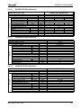
2.96
2.92
2.92
2.88
2.85
3.02
2.98
2.83
2.89
2.87
2.85
2.91
2.82
2.83
2.85
2.85
2.86
2.89
2.89
2.88
2.94
2.89
2.89
2.89
2.89
3.18
3.25
3.38
3.38
3.38
SM CINCO 1-A.1 GB
5-1
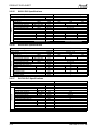
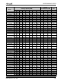
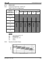
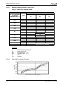
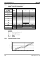
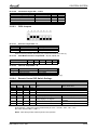
PERFORMANCE DATA
9+12+12
9+12+18
9+12+21
9+12+24
9+18+18
9+18+21
9+18+24
9+21+21
9+21+24
12+12+12
12+12+18
12+12+21
12+12+24
12+18+18
12+18+21
7+7+7+7
7+7+7+9
7+7+7+12
7+7+7+18
7+7+7+21
7+7+7+24
7+7+9+9
7+7+9+12
7+7+9+18
7+7+9+21
7+7+9+24
7+7+12+12
7+7+12+18
7+7+12+21
7+7+18+18
7+9+9+9
7+9+9+12
7+9+9+18
7+9+9+21
7+9+9+24
7+9+12+12
7+9+12+18
7+9+12+21
7+9+18+18
7+9+18+21
7+12+12+12
7+12+12+18
7+12+12+21
9+9+9+9
9+9+9+12
9+9+9+18
9+9+9+21
9+9+9+24
9+9+12+12
9+9+12+18
9+9+12+21
9+9+18+18
9+12+12+12
9+12+12+18
9+12+12+21
12+12+12+12
7+7+7+7+7
7+7+7+7+9
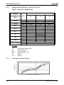
5-2
Power
Consumption [kW]
Cooling Capacity [KW]
Model
EER
A
B
C
D
E
Nom.
Min.
Max.
Nom.
Min.
Max.
Nom.
2.2
2.0
2.0
1.9
1.9
1.8
1.7
1.7
1.6
2.8
2.6
2.5
2.4
2.4
2.2
1.7
1.6
1.5
1.3
1.2
1.2
1.5
1.4
1.2
1.2
1.1
1.3
1.2
1.1
1.1
1.4
1.3
1.2
1.1
1.1
1.3
1.1
1.1
1.1
1.0
1.2
1.1
1.1
2.2
2.1
1.9
1.9
1.8
2.0
1.9
2.0
1.7
1.9
1.8
1.7
2.5
1.9
1.8
3.0
2.7
2.6
2.5
2.8
2.6
2.5
2.4
1.7
1.6
1.5
1.3
1.2
1.2
1.5
1.4
1.2
1.2
1.1
1.3
1.2
1.1
1.1
1.8
1.7
1.5
1.5
1.5
1.6
1.5
1.5
1.4
1.3
2.1
1.9
1.8
2.2
2.1
1.9
1.9
1.8
2.0
1.9
2.0
1.7
2.6
2.4
2.2
2.5
1.9
1.8
3.0
2.8
1.7
1.6
1.5
1.3
1.2
1.2
2.0
1.8
1.6
1.5
1.5
2.2
2.0
2.0
1.8
1.7
1.5
1.5
1.5
2.2
2.0
1.9
2.1
1.9
1.8
2.2
2.1
1.9
1.9
1.8
2.7
2.5
2.7
3.3
2.6
2.4
2.2
2.5
1.9
1.8
3.8
3.6
3.4
3.9
3.7
3.6
3.4
1.7
2.1
2.6
3.2
3.7
4.1
2.0
2.4
3.2
3.6
3.9
2.2
3.1
3.4
2.9
1.8
2.3
3.1
3.4
3.9
2.2
2.9
3.4
2.7
3.0
2.1
2.9
3.2
2.2
2.8
3.9
4.4
4.7
2.7
3.8
2.7
3.3
2.6
3.5
3.9
2.5
1.9
1.8
4.1
4.6
5.1
3.8
4.2
4.5
3.9
4.2
3.9
4.4
4.8
3.6
3.9
2.9
2.7
2.6
1.9
2.3
8.2
8.8
9.2
9.5
9.5
9.5
9.5
9.5
9.5
8.5
9.2
9.5
9.5
9.5
9.5
6.9
7.0
7.0
7.0
7.5
7.7
7.0
7.0
7.2
7.5
7.7
7.0
7.5
7.7
7.9
7.0
7.0
7.3
7.5
7.9
7.2
7.5
7.9
7.9
7.9
7.5
7.9
7.9
8.8
9.1
9.7
10.0
10.0
9.4
10.0
9.4
10.0
9.7
10.0
10.0
10.0
9.5
9.6
2.9
3.1
3.2
3.3
3.3
3.4
3.5
3.5
3.6
3.0
3.2
3.3
3.4
3.4
3.5
3.00
3.1
3.3
3.6
3.7
3.9
3.2
3.4
3.7
3.8
4.0
3.5
3.8
4.0
4.1
3.3
3.5
3.8
3.9
4.1
3.6
3.9
4.1
4.2
4.4
3.8
4.1
4.2
3.4
3.6
3.9
4.0
4.2
3.7
4.0
3.7
4.3
3.9
4.2
4.3
4.0
4.00
4.1
9.3
9.7
9.9
10.1
10.1
10.3
10.5
10.5
10.5
9.5
9.9
10.1
10.3
10.3
10.5
9.0
9.2
9.5
10.1
10.4
10.7
9.4
9.7
10.3
10.6
10.9
10.0
10.6
10.9
11.0
9.6
9.9
10.5
10.8
11.0
10.2
10.8
11.0
11.0
11.0
10.5
11.0
11.0
9.8
10.1
10.7
11.0
11.0
10.4
11.0
10.4
11.0
10.7
11.0
11.0
11.0
10.2
10.4
2.46
2.61
2.71
2.81
2.81
2.81
2.81
2.81
2.81
2.51
2.71
2.81
2.81
2.81
2.81
2.18
2.19
2.21
2.15
2.30
2.36
2.19
2.21
2.20
2.30
2.35
2.21
2.30
2.35
2.45
2.14
2.21
2.23
2.30
2.43
2.20
2.30
2.45
2.45
2.43
2.30
2.45
2.43
2.33
2.38
2.46
2.50
2.50
2.42
2.50
2.42
2.50
2.46
2.50
2.50
2.50
3.11
3.13
0.69
0.70
0.68
0.68
0.66
0.66
0.66
0.66
0.66
0.72
0.70
0.68
0.68
0.68
0.66
0.81
0.81
0.81
0.79
0.77
0.77
0.81
0.81
0.79
0.77
0.77
0.81
0.79
0.77
0.77
0.81
0.81
0.79
0.77
0.77
0.81
0.81
0.77
0.77
0.77
0.81
0.79
0.77
0.81
0.81
0.79
0.77
0.77
0.81
0.79
0.77
0.77
0.81
0.79
0.79
0.81
0.78
0.78
2.92
2.89
3.00
3.02
3.02
3.02
3.05
3.05
3.20
2.91
3.00
3.02
3.05
3.02
3.05
2.67
2.67
2.65
2.62
2.75
2.73
2.67
2.65
2.70
2.71
2.75
2.62
2.71
2.75
2.90
2.67
2.65
2.71
2.75
2.89
2.70
2.75
2.89
2.89
3.03
2.71
2.75
2.89
2.67
2.65
2.71
2.75
2.89
2.71
2.75
2.89
2.89
2.61
2.89
2.89
2.92
3.50
3.50
3.31
3.38
3.38
3.38
3.38
3.38
3.38
3.38
3.38
3.38
3.38
3.38
3.38
3.38
3.38
3.15
3.17
3.19
3.27
3.25
3.24
3.17
3.19
3.28
3.25
3.26
3.19
3.25
3.26
3.23
3.25
3.19
3.28
3.25
3.26
3.28
3.25
3.23
3.23
3.26
3.25
3.23
3.26
3.77
3.83
3.94
4.00
4.00
3.89
4.00
3.89
4.00
3.94
4.00
4.00
4.00
3.05
3.07
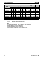
SM CINCO 1-A.1 GB
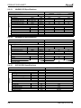
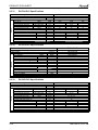
PERFORMANCE DATA
7+7+7+7+12
7+7+7+7+18
7+7+7+7+21
7+7+7+9+9
7+7+7+9+12
7+7+7+9+18
7+7+7+12+12
7+7+9+9+9
7+7+9+9+12
7+7+9+9+18
7+7+9+12+12
7+9+9+9+9
7+9+9+9+12
7+9+9+9+18
7+9+9+12+12
9+9+9+9+9
9+9+9+9+12
9+9+9+9+18
9+9+9+12+12
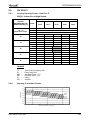
Power
Consumption [kW]
Cooling Capacity [KW]
Model
EER
A
B
C
D
E
Nom.
Min.
Max.
Nom.
Min.
Max.
Nom.
1.7
1.5
1.4
1.7
1.6
1.5
1.6
1.7
1.6
1.4
1.5
1.6
1.5
1.3
1.3
2.0
1.9
1.8
1.9
1.7
1.5
1.4
1.7
1.6
1.5
1.6
1.7
1.6
1.4
1.5
2.1
2.0
1.7
1.7
2.0
1.9
1.8
1.9
1.7
1.5
1.4
1.7
1.6
1.5
1.6
2.2
2.0
1.8
1.9
2.1
2.0
1.7
1.7
2.0
1.9
1.8
1.9
1.7
1.5
1.4
2.2
2.1
1.9
2.1
2.2
2.0
1.8
2.6
2.1
2.0
1.7
1.7
2.0
1.9
1.8
2.5
2.9
3.9
4.3
2.2
2.8
3.8
2.8
2.2
2.7
3.6
2.6
2.1
2.6
3.5
3.5
2.0
2.6
3.5
2.5
9.8
10.0
10.0
9.7
9.9
10.0
9.9
9.8
10.0
10.0
10.0
9.9
10.0
10.0
10.0
10.0
10.3
10.5
10.5
4.2
4.3
4.4
4.1
4.2
4.4
4.2
4.2
4.3
4.5
4.4
4.3
4.3
4.5
4.5
4.3
4.4
4.6
4.50
10.6
11.0
11.0
10.5
10.8
11.0
10.8
10.7
10.9
11.0
11.0
10.8
11.0
11.0
11.0
11.0
11.0
11.0
11.0
3.15
3.17
3.17
3.14
3.16
3.17
3.16
3.15
3.17
3.17
3.17
3.16
3.17
3.17
3.17
3.17
3.08
3.00
3.00
0.78
0.79
0.80
0.78
0.78
0.79
0.78
0.78
0.78
0.79
0.78
0.78
0.78
0.79
0.78
0.78
0.78
0.79
0.78
3.50
3.49
3.48
3.50
3.50
3.49
3.50
3.50
3.50
3.49
3.50
3.50
3.50
3.49
3.50
3.50
3.50
3.49
3.50
3.10
3.15
3.15
3.09
3.12
3.15
3.12
3.11
3.14
3.15
3.15
3.13
3.15
3.15
3.15
3.15
3.33
3.50
3.50
Nominal Indoor Units Combination
Notes:
(1) Units 22 – Delta (HFD/HAD). Units 25,35,50,60,70 – LEX (PNX/WNG).
(2) Rating conditions in accordance with ISO 5151.
(3) Power Input/EER/COP are for complete system.
(4) Running Current is measured in nominal conditions at 230V.
SM CINCO 1-A.1 GB
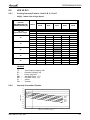
5-3
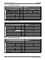
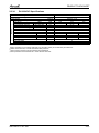
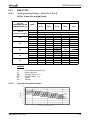
PERFORMANCE DATA
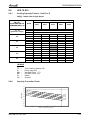
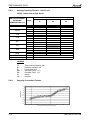
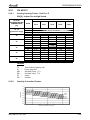
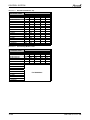
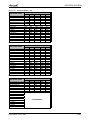
5.1.2
Heating
7
9
12
18
21
24
7+7
7+9
7+12
7+18
7+21
7+24
9+9
9+12
9+18
9+21
9+24
12+12
12+18
12+21
12+24
18+18
18+21
18+24
21+21
21+24
24+24
7+7+7
7+7+9
7+7+12
7+7+18
7+7+21
7+7+24
7+9+9
7+9+12
7+9+18
7+9+21
7+9+24
7+12+12
7+12+18
7+12+21
7+12+24
7+18+18
7+18+21
7+18+24
7+21+21
7+21+24
9+9+9
9+9+12
9+9+18
9+9+21
9+9+24
9+12+12
9+12+18
9+12+21
9+12+24
9+18+18
5-4
Power
Consumption [kW]
Heating Capacity [KW]
Model
COP
A
B
C
D
E
Nom.
Min.
Max.
Nom.
Min.
Max.
Nom.
2.8
3.4
4.3
2.6
2.5
2.5
2.4
2.3
2.1
3.0
3.1
3.0
2.8
2.6
4.2
3.7
3.4
3.2
2.3
2.2
2.2
1.8
1.7
1.5
2.1
2.0
1.7
1.6
1.5
1.9
1.6
1.5
1.4
1.4
1.3
1.3
1.3
1.3
3.3
3.0
2.6
2.4
2.2
2.8
2.4
2.2
2.1
2.1
2.6
3.2
4.3
3.0
4.1
4.2
2.3
2.2
2.2
1.8
1.7
1.5
2.7
2.6
2.2
2.0
1.9
3.2
2.7
2.5
2.5
3.3
3.0
2.6
2.4
2.2
3.7
3.2
3.0
2.8
-
2.3
2.8
3.7
2.7
3.5
3.2
3.3
4.1
3.7
-
5.3
4.9
4.6
5.3
5.0
5.4
3.6
3.5
3.4
4.0
3.8
4.2
6.0
6.5
7.6
6.2
7.0
7.3
6.0
6.5
6.9
5.6
6.0
6.4
5.3
5.7
6.1
5.3
5.7
5.4
4.6
5.0
5.3
4.3
4.7
5.0
4.0
4.4
4.9
3.6
4.0
4.6
4.0
4.4
5.2
5.6
5.9
4.8
5.2
5.5
4.2
2.8
3.4
4.3
6.0
6.5
7.6
5.3
5.6
6.8
8.6
9.3
9.5
6.0
7.2
9.0
9.3
9.5
8.4
9.3
9.5
9.6
10.5
10.6
10.7
10.7
10.7
10.8
6.9
7.2
8.0
8.2
8.3
8.3
7.5
8.1
8.2
8.3
8.3
8.2
8.2
8.3
8.8
8.6
8.8
9.4
9.4
9.5
10.0
10.1
10.4
10.4
10.4
10.3
10.4
10.4
10.4
10.4
0.95
0.95
1.11
1.50
1.80
2.00
2.0
2.1
2.1
2.3
2.4
2.5
2.1
2.2
2.4
2.5
2.6
2.3
2.5
2.6
2.6
2.6
2.7
2.8
2.8
2.9
3.0
2.5
2.6
2.7
2.9
3.0
3.1
2.6
2.7
2.9
3.0
3.1
2.8
3.0
3.1
3.2
3.2
3.3
3.4
3.4
3.5
2.7
2.8
3.0
3.1
3.2
2.9
3.1
3.2
3.3
3.3
4.0
5.2
7.5
7.6
7.9
8.8
7.0
7.3
7.7
8.6
9.1
9.5
7.6
8.0
8.9
9.4
9.8
8.5
9.4
9.8
10.2
11.5
11.0
11.0
11.0
11.0
12.0
8.5
8.7
9.1
9.8
10.1
10.5
9.0
9.3
10.0
10.4
10.7
9.7
10.4
10.7
11.1
11.1
11.4
11.8
11.8
12.0
11.0
11.1
11.4
11.5
11.6
11.3
11.5
11.6
11.8
11.8
0.60
0.69
0.95
1.50
1.85
2.42
1.13
1.27
1.71
2.45
2.75
2.81
1.36
2.01
2.58
2.75
2.81
2.40
2.76
2.73
2.78
2.94
2.98
3.02
3.02
3.05
3.09
1.86
1.97
2.31
2.32
2.37
2.39
2.10
2.35
2.37
2.39
2.39
2.35
2.32
2.35
2.51
2.40
2.50
2.65
2.65
2.68
2.44
2.53
2.60
2.62
2.64
2.57
2.62
2.64
2.67
2.67
0.30
0.40
0.39
0.46
0.40
0.41
0.60
0.60
0.60
0.56
0.56
0.56
0.58
0.54
0.56
0.56
0.56
0.54
0.56
0.56
0.56
0.59
0.57
0.55
0.55
0.55
0.55
0.69
0.67
0.69
0.70
0.68
0.68
0.69
0.69
0.70
0.68
0.68
0.69
0.70
0.68
0.68
0.68
0.66
0.66
0.66
0.60
0.69
0.69
0.70
0.68
0.68
0.69
0.70
0.68
0.68
0.66
0.80
0.86
1.21
1.87
2.13
2.71
1.60
1.77
2.20
2.71
3.05
3.20
1.95
2.54
3.20
3.28
3.32
2.55
3.22
3.18
3.18
3.16
3.12
3.20
3.20
3.20
3.40
2.41
2.51
2.97
2.92
2.88
2.88
2.94
2.97
2.92
2.88
2.88
2.92
2.89
2.86
3.00
3.05
3.02
3.05
3.05
3.21
3.01
2.97
2.92
2.88
3.05
2.92
2.89
3.00
3.02
3.02
4.67
4.96
4.54
4.01
3.51
3.14
4.66
4.43
3.99
3.52
3.40
3.37
4.40
3.58
3.48
3.40
3.37
3.49
3.38
3.47
3.45
3.58
3.56
3.53
3.53
3.51
3.49
3.69
3.64
3.47
3.54
3.51
3.48
3.57
3.45
3.47
3.48
3.48
3.50
3.54
3.54
3.52
3.60
3.54
3.53
3.53
3.53
4.10
4.00
4.00
3.97
3.93
4.00
3.97
3.93
3.90
3.90
SM CINCO 1-A.1 GB
PERFORMANCE DATA
9+18+21
9+18+24
9+21+21
9+21+24
12+12+12
12+12+18
12+12+21
12+12+24
12+18+18
12+18+21
7+7+7+7
7+7+7+9
7+7+7+12
7+7+7+18
7+7+7+21
7+7+7+24
7+7+9+9
7+7+9+12
7+7+9+18
7+7+9+21
7+7+9+24
7+7+12+12
7+7+12+18
7+7+12+21
7+7+18+18
7+9+9+9
7+9+9+12
7+9+9+18
7+9+9+21
7+9+9+24
7+9+12+12
7+9+12+18
7+9+12+21
7+9+18+18
7+9+18+21
7+12+12+12
7+12+12+18
7+12+12+21
9+9+9+9
9+9+9+12
9+9+9+18
9+9+9+21
9+9+9+24
9+9+12+12
9+9+12+18
9+9+12+21
9+9+18+18
9+12+12+12
9+12+12+18
9+12+12+21
12+12+12+12
7+7+7+7+7
7+7+7+7+9
7+7+7+7+12
7+7+7+7+18
7+7+7+7+21
7+7+7+9+9
7+7+7+9+12
Power
Consumption [kW]
Heating Capacity [KW]
Model
COP
A
B
C
D
E
Nom.
Min.
Max.
Nom.
Min.
Max.
Nom.
2.0
1.8
1.8
1.7
3.5
3.0
2.9
2.7
2.7
2.6
2.0
1.8
1.7
1.4
1.4
1.4
1.7
1.6
1.4
1.4
1.3
1.5
1.4
1.3
1.3
1.6
1.5
1.4
1.3
1.3
1.4
1.3
1.3
1.2
1.1
1.4
1.3
1.2
2.5
2.4
2.2
2.1
1.9
2.3
2.1
2.3
1.8
2.2
1.9
1.8
2.8
2.2
2.1
2.0
1.8
1.7
2.0
2.0
3.5
3.0
2.9
2.7
2.0
1.8
1.7
1.4
1.4
1.4
1.7
1.6
1.4
1.4
1.3
1.5
1.4
1.3
1.3
2.1
1.9
1.7
1.7
1.7
1.8
1.7
1.7
1.6
1.5
2.4
2.2
2.1
2.5
2.4
2.2
2.1
1.9
2.3
2.1
2.3
1.8
2.9
2.6
2.4
2.8
2.2
2.1
2.0
1.8
1.7
2.0
2.0
3.5
2.0
1.8
1.7
1.4
1.4
1.4
2.2
2.1
1.8
1.7
1.7
2.5
2.3
2.2
2.1
1.9
1.7
1.7
1.7
2.5
2.2
2.2
2.4
2.2
2.1
2.5
2.4
2.2
2.1
1.9
3.0
2.8
3.0
3.7
2.9
2.6
2.4
2.8
2.2
2.1
2.0
1.8
1.7
2.0
2.0
3.9
3.7
4.3
4.0
4.1
3.9
2.0
2.4
2.9
3.7
4.3
4.6
2.2
2.7
3.6
4.1
4.4
2.5
3.5
3.9
3.2
2.1
2.6
3.5
3.9
4.4
2.5
3.3
3.9
3.1
3.4
2.4
3.3
3.6
2.5
3.2
4.3
4.8
5.2
3.0
4.1
3.0
3.7
2.9
3.9
4.3
2.8
2.2
2.1
2.0
1.8
1.7
2.6
2.5
4.6
4.9
4.3
4.6
4.6
5.0
5.5
4.1
4.6
3.2
3.1
2.9
2.2
2.7
3.5
4.7
5.1
2.6
3.3
10.4
10.4
10.4
10.4
10.4
10.7
10.8
10.9
10.9
11.1
7.8
7.9
8.0
8.0
8.5
8.7
7.9
8.0
8.2
8.5
8.7
8.0
8.5
8.7
9.0
7.9
8.0
8.3
8.5
9.0
8.2
8.5
9.0
9.0
9.0
8.5
9.0
9.0
10.0
10.3
10.8
11.0
11.0
10.5
11.0
10.5
11.0
10.8
11.0
11.0
11.0
11.0
11.2
11.5
12.0
12.0
11.4
11.7
3.4
3.5
3.5
3.6
3.0
3.2
3.3
3.4
3.4
3.5
3.0
3.1
3.3
3.6
3.7
3.9
3.2
3.4
3.7
3.8
4.0
3.5
3.8
4.0
4.1
3.3
3.5
3.8
3.9
4.1
3.6
3.9
4.1
4.2
4.4
3.8
4.1
4.2
3.4
3.6
3.9
4.0
4.2
3.7
4.0
3.7
4.3
3.9
4.2
4.3
4.0
4.0
4.1
4.2
4.3
4.4
4.1
4.2
11.9
12.0
12.0
12.0
11.4
11.6
11.8
11.9
11.9
12.0
9.0
9.3
9.6
10.4
10.8
11.1
9.5
9.9
10.6
11.0
11.4
10.3
11.0
11.4
11.5
9.8
10.1
10.9
11.3
11.5
10.5
11.3
11.5
11.5
11.5
10.9
11.5
11.5
10.4
10.4
11.1
11.5
11.5
10.8
11.5
10.8
11.5
11.1
11.5
11.5
11.5
11.2
11.5
11.9
12.5
12.5
11.7
12.1
2.69
2.71
2.71
2.74
2.60
2.71
2.77
2.83
2.83
2.89
2.18
2.17
2.16
2.39
2.38
2.38
2.16
2.15
2.38
2.37
2.37
2.15
2.37
2.36
2.27
2.16
2.15
2.38
2.36
2.36
2.52
2.35
2.34
2.26
2.25
2.55
2.35
2.34
2.08
2.23
2.56
2.75
2.89
2.39
2.75
2.39
3.06
2.56
2.89
3.06
2.75
2.89
2.89
2.88
2.86
2.86
2.88
2.87
0.66
0.66
0.66
0.66
0.72
0.70
0.68
0.68
0.68
0.66
0.81
0.81
0.81
0.79
0.77
0.77
0.81
0.81
0.79
0.77
0.77
0.81
0.79
0.77
0.77
0.81
0.81
0.79
0.77
0.77
0.81
0.81
0.77
0.77
0.77
0.81
0.79
0.77
0.81
0.81
0.79
0.77
0.77
0.81
0.79
0.77
0.77
0.81
0.79
0.79
0.81
0.78
0.78
0.78
0.79
0.80
0.78
0.78
3.02
3.05
3.05
3.20
2.91
3.00
3.02
3.05
3.02
3.05
2.67
2.67
2.65
2.62
2.75
2.73
2.67
2.65
2.70
2.71
2.75
2.62
2.71
2.75
2.90
2.67
2.65
2.71
2.75
2.89
2.70
2.75
2.89
2.89
3.03
2.71
2.75
2.89
2.67
2.65
2.71
2.75
2.89
2.71
2.75
2.89
2.89
2.61
2.89
2.89
2.92
3.50
3.50
3.50
3.49
3.48
3.50
3.50
3.87
3.83
3.83
3.80
4.00
3.93
3.90
3.87
3.87
3.83
3.58
3.64
3.70
3.35
3.57
3.66
3.66
3.72
3.45
3.59
3.67
3.72
3.59
3.69
3.96
3.66
3.72
3.49
3.60
3.81
3.25
3.62
3.85
3.98
4.00
3.33
3.83
3.85
4.80
4.60
4.20
4.00
3.80
4.40
4.00
4.40
3.60
4.20
3.80
3.60
4.00
3.80
3.88
4.00
4.20
4.20
3.96
4.08
SM CINCO 1-A.1 GB
5-5
PERFORMANCE DATA
7+7+7+9+18
7+7+7+12+12
7+7+9+9+9
7+7+9+9+12
7+7+9+9+18
7+7+9+12+12
7+9+9+9+9
7+9+9+9+12
7+9+9+9+18
7+9+9+12+12
9+9+9+9+9
9+9+9+9+12
9+9+9+9+18
9+9+9+12+12
Power
Consumption [kW]
Heating Capacity [KW]
Model
COP
A
B
C
D
E
Nom.
Min.
Max.
Nom.
Min.
Max.
Nom.
1.8
2.0
2.0
1.9
1.7
1.8
1.9
1.8
1.6
1.6
2.4
2.3
2.0
2.2
1.8
2.0
2.0
1.9
1.7
1.8
2.5
2.3
2.1
2.1
2.4
2.3
2.0
2.2
1.8
2.0
2.5
2.4
2.2
2.3
2.5
2.3
2.1
2.1
2.4
2.3
2.0
2.2
2.3
2.5
2.5
2.4
2.2
3.1
2.5
2.3
2.1
2.1
2.4
2.3
2.0
2.9
4.5
3.3
2.5
3.2
4.3
3.1
2.5
3.1
4.2
4.2
2.4
3.0
4.1
2.9
12.0
11.7
11.6
11.9
12.0
12.0
11.8
12.0
12.0
12.0
12.0
12.1
12.2
12.2
4.4
4.2
4.2
4.3
4.5
4.4
4.3
4.3
4.5
4.5
4.3
4.4
4.6
4.5
12.5
12.1
12.0
12.4
12.5
12.5
12.2
12.5
12.5
12.5
12.5
12.5
12.5
12.5
2.86
2.87
2.87
2.86
2.86
2.86
2.86
2.86
2.86
2.86
2.86
2.83
2.80
2.80
0.79
0.78
0.78
0.78
0.79
0.78
0.78
0.78
0.79
0.78
0.78
0.78
0.79
0.78
3.49
3.50
3.50
3.50
3.49
3.50
3.50
3.50
3.49
3.50
3.50
3.50
3.49
3.50
4.20
4.08
4.04
4.16
4.20
4.20
4.12
4.20
4.20
4.20
4.20
4.28
4.35
4.35
Nominal Indoor Units Combination
Notes:
(1) Units 22 – Delta (HFD/HAD). Units 25,35,50,60,70 – LEX (PNX/WNG).
(2) Rating conditions in accordance with ISO 5151.
(3) Power Input/EER/COP are for complete system.
(4) Running Current is measured in nominal conditions at 230V.
5-6
SM CINCO 1-A.1 GB
PERFORMANCE DATA
5.2
LEX 25 DCI
5.2.1
Cooling Capacity Factors - Unit A, B, C, D or E
230[V] : Indoor Fan at High Speed.
ID COIL ENTERING AIR DB/WB TEMPERATURE [ºC]
OD COIL
ENTERING AIR DB
TEMPERATURE [ºC]
-10 - 20
(protection range)
25
30
35
40
46
DATA
TC
SC
PI
TC
SC
PI
TC
SC
PI
TC
SC
PI
TC
SC
PI
TC
SC
PI
22/15
24/17
27/19
29/21
32/23
0.97
1.01
0.79
0.92
0.98
0.88
0.87
0.96
0.97
0.83
0.93
1.06
0.77
0.90
1.17
80 - 110 % of nominal
80 - 105 % of nominal
25 - 50 % of nominal
1.03
1.09
1.16
1.03
1.05
1.07
0.80
0.82
0.83
0.98
1.05
1.11
1.00
1.03
1.05
0.91
0.89
0.92
0.94
1.06
1.00
0.98
1.00
1.02
1.00
0.99
1.02
0.89
1.02
0.95
0.95
0.97
1.00
1.08
1.09
1.11
0.83
0.90
0.96
0.92
0.94
0.96
1.19
1.20
1.22
1.22
1.09
0.85
1.17
1.07
0.94
1.13
1.04
1.03
1.08
1.02
1.12
1.02
0.99
1.23
LEGEND
TC
SC
PI
WB
DB
ID
OD
5.2.2
–
–
–
–
–
–
–
Total Cooling Capacity, kW
Sensible Capacity, kW
Power Input, kW
Wet Bulb Temp., (oC)
Dry Bulb Temp., (oC)
Indoor
Outdoor
Capacity Correction Factors
1.4
1.3
Capacity Ratio
1.2
1.1
32/23
29/21
27/19
1.0
0.9
24/17
22/15
0.8
0.7
0.6
0.5
20
SM CINCO 1-A.1 GB
25
30
35
40
Outdoor Temperature [deg C]
45
50
5-7
PERFORMANCE DATA
5.2.3
Heating Capacity Factors - Unit A, B, C, D or E
230[V] : Indoor Fan at High Speed.
OD COIL ENTERING
AIR DB/WB
TEMPERATURE [ºC]
ID COIL ENTERING AIR DB TEMPERATURE [ºC]
DATA
-15/-16
-10/-12
-7/-8
-1/-2
2/1
7/6
10/9
15/12
15-24
(Protection Range)
15
20
25
TC
PI
TC
PI
TC
PI
TC
PI
TC
0.64
0.60
0.71
0.72
0.76
0.82
0.79
0.86
0.81
0.55
0.72
0.62
0.85
0.67
0.94
0.70
0.98
0.72
PI
0.89
0.59
0.66
0.66
0.78
0.72
0.88
0.75
0.92
0.76
0.95
TC
PI
TC
PI
TC
PI
TC
PI
1.04
0.94
1.10
1.00
1.16
1.05
1.00
1.00
0.96
1.06
1.01
1.12
1.07
1.17
1.01
1.06
1.06
1.12
1.11
85 - 105 % of nominal
80 - 120 % of nominal
LEGEND
TC
PI
WB
DB
ID
OU
5.2.4
–
–
–
–
–
–
Total Heating Capacity, kW
Power Input, kW
Wet Bulb Temp., (oC)
Dry Bulb Temp., (oC)
Indoor
Outdoor
Capacity Correction Factors
1.3
1.2
15
20
25
1.1
Capacity Ratio
1.0
0.9
0.8
0.7
0.6
0.5
0.4
0.3
-20
5-8
-15
-10
-5
0
5
Outdoor WB Temperature [deg C]
10
15
SM CINCO 1-A.1 GB
PERFORMANCE DATA
5.3
LEX 35 DCI
5.3.1
Cooling Capacity Factors - Unit A, B, C, D or E
230[V] : Indoor Fan at High Speed.
OD COIL
ENTERING AIR DB
TEMPERATURE [ºC]
-10 - 20
(protection range)
25
30
35
40
46
ID COIL ENTERING AIR DB/WB TEMPERATURE [ºC]
DATA
TC
SC
PI
TC
SC
PI
TC
SC
PI
TC
SC
PI
TC
SC
PI
TC
SC
PI
22/15
24/17
27/19
29/21
32/23
0.97
1.01
0.79
0.92
0.98
0.88
0.87
0.96
0.97
0.83
0.93
1.06
0.77
0.90
1.17
80 - 110 % of nominal
80 - 105 % of nominal
25 - 50 % of nominal
1.03
1.09
1.16
1.03
1.05
1.07
0.80
0.82
0.83
0.98
1.05
1.11
1.00
1.03
1.05
0.91
0.89
0.92
0.94
1.06
1.00
0.98
1.00
1.02
1.00
0.99
1.02
0.89
1.02
0.95
0.95
0.97
1.00
1.08
1.09
1.11
0.83
0.90
0.96
0.92
0.94
0.96
1.19
1.20
1.22
1.22
1.09
0.85
1.17
1.07
0.94
1.13
1.04
1.03
1.08
1.02
1.12
1.02
0.99
1.23
LEGEND
TC
PI
WB
DB
ID
OD
5.3.2
–
–
–
–
–
–
Total Cooling Capacity, kW
Power Input, kW
Wet Bulb Temp., (oC)
Dry Bulb Temp., (oC)
Indoor
Outdoor
Capacity Correction Factors
1.4
1.3
Capacity Ratio
1.2
1.1
32/23
29/21
27/19
24/17
22/15
1.0
0.9
0.8
0.7
0.6
0.5
20
SM CINCO 1-A.1 GB
25
30
35
40
Outdoor Temperature [deg C]
45
50
5-9
PERFORMANCE DATA
5.3.3
Heating Capacity Factors - Unit A, B, C, D or E
230[V] : Indoor Fan at High Speed.
OD COIL
ENTERING
AIR DB/WB
TEMPERATURE
[ºC]
-15/-16
-10/-12
-7/-8
-1/-2
2/1
7/6
10/9
15/12
15-24
(Protection Range)
ID COIL ENTERING AIR DB TEMPERATURE [ºC]
DATA
TC
PI
TC
PI
TC
PI
TC
PI
TC
PI
TC
PI
TC
PI
TC
PI
TC
PI
15
20
25
0.64
0.60
0.71
0.72
0.76
0.82
0.79
0.86
0.81
0.89
1.04
0.94
1.10
1.00
1.16
1.05
0.59
0.66
0.66
0.78
0.72
0.88
0.75
0.92
0.76
0.95
0.55
0.72
0.62
0.85
0.67
0.94
0.70
0.98
0.72
1.01
0.96
1.06
1.01
1.12
1.07
1.17
1.00
1.00
1.06
1.06
1.12
1.11
85 - 105 % of nominal
80 - 120 % of nominal
LEGEND
TC
PI
WB
DB
ID
OU
5.3.4
–
–
–
–
–
–
Total Heating Capacity, kW
Power Input, kW
Wet Bulb Temp., (oC)
Dry Bulb Temp., (oC)
Indoor
Outdoor
Capacity Correction Factors
1.3
1.2
15
20
25
Capacity Ratio
1.1
1.0
0.9
0.8
0.7
0.6
0.5
0.4
0.3
-20
5-10
-15
-10
-5
0
5
Outdoor WB Temperature [deg C]
10
15
SM CINCO 1-A.1 GB
PERFORMANCE DATA
5.4
LEX 50 DCI
5.4.1
Cooling Capacity Factors - Unit D or E
230[V] : Indoor Fan at High Speed.
OD COIL
ENTERING AIR DB
TEMPERATURE [ºC]
-10 - 20
(protection range)
25
30
35
40
46
ID COIL ENTERING AIR DB/WB TEMPERATURE [ºC]
DATA
TC
SC
PI
TC
SC
PI
TC
SC
PI
TC
SC
PI
TC
SC
PI
TC
SC
PI
22/15
24/17
27/19
29/21
32/23
0.99
1.05
0.76
0.93
1.01
0.86
0.88
0.97
0.97
0.83
0.93
1.07
0.77
0.88
1.20
80 - 110 % of nominal
80 - 105 % of nominal
25 - 50 % of nominal
1.04
1.10
1.16
1.07
1.08
1.10
0.77
0.79
0.81
0.99
1.05
1.11
1.03
1.04
1.06
0.90
0.88
0.91
0.94
1.06
1.00
0.98
1.00
1.02
1.00
0.98
1.02
0.89
1.01
0.95
0.94
0.96
0.97
1.09
1.11
1.12
0.83
0.89
0.95
0.89
0.91
0.93
1.21
1.23
1.25
1.22
1.11
0.82
1.17
1.07
0.93
1.12
1.03
1.03
1.07
0.99
1.14
1.00
0.94
1.27
LEGEND
TC
PI
WB
DB
ID
OD
5.4.2
–
–
–
–
–
–
Total Cooling Capacity, kW
Power Input, kW
Wet Bulb Temp., (oC)
Dry Bulb Temp., (oC)
Indoor
Outdoor
Capacity Correction Facto
1.4
1.3
Capacity Ratio
1.2
1.1
32/23
29/21
27/19
1.0
0.9
24/17
22/15
0.8
0.7
0.6
0.5
20
SM CINCO 1-A.1 GB
25
30
35
40
Outdoor Temperature [deg C]
45
50
5-11
PERFORMANCE DATA
5.4.3
Heating Capacity Factors - Unit D or E
230[V] : Indoor Fan at High Speed.
OD COIL
ENTERING
AIR DB/WB
TEMPERATURE
[ºC]
-15/-16
-10/-12
-7/-8
-1/-2
2/1
7/6
10/9
15/12
15-24
(Protection Range)
ID COIL ENTERING AIR DB TEMPERATURE [ºC]
DATA
TC
PI
TC
PI
TC
PI
TC
PI
TC
PI
TC
PI
TC
PI
TC
PI
TC
PI
15
20
25
0.46
0.70
0.60
0.79
0.71
0.86
0.76
0.89
0.80
0.92
1.07
0.95
1.12
0.97
1.18
0.99
0.39
0.75
0.54
0.84
0.64
0.91
0.70
0.94
0.74
0.97
0.32
0.80
0.47
0.89
0.58
0.96
0.63
0.99
0.67
1.02
0.93
1.05
0.99
1.07
1.04
1.09
1.00
1.00
1.06
1.02
1.11
1.04
85 - 105 % of nominal
80 - 120 % of nominal
LEGEND
TC
SC
PI
WB
DB
ID
OD
5.5.4
–
–
–
–
–
–
–
Total Cooling Capacity, kW
Sensible Capacity, kW
Power Input, kW
Wet Bulb Temp., (oC)
Dry Bulb Temp., (oC)
Indoor
Outdoor
Capacity Correction Factors
1.3
1.2
15
20
25
1.1
Capacity Ratio
1.0
0.9
0.8
0.7
0.6
0.5
0.4
0.3
-20
5-12
-15
-10
-5
0
5
Outdoor WB Temperature [deg C]
10
15
SM CINCO 1-A.1 GB
PERFORMANCE DATA
5.5
LEX 60 DCI
5.5.1
Cooling Capacity Factors - Unit D or E
230[V] : Indoor Fan at High Speed.
OD COIL
ENTERING AIR DB
TEMPERATURE [ºC]
-10 - 20
(protection range)
25
30
35
40
46
ID COIL ENTERING AIR DB/WB TEMPERATURE [ºC]
DATA
TC
SC
PI
TC
SC
PI
TC
SC
PI
TC
SC
PI
TC
SC
PI
TC
SC
PI
22/15
24/17
27/19
29/21
32/23
0.99
1.05
0.76
0.93
1.01
0.86
0.88
0.97
0.97
0.83
0.93
1.07
0.77
0.88
1.20
80 - 110 % of nominal
80 - 105 % of nominal
25 - 50 % of nominal
1.04
1.10
1.16
1.07
1.08
1.10
0.77
0.79
0.81
0.99
1.05
1.11
1.03
1.04
1.06
0.90
0.88
0.91
0.94
1.06
1.00
0.98
1.00
1.02
1.00
0.98
1.02
0.89
1.01
0.95
0.94
0.96
0.97
1.09
1.11
1.12
0.83
0.89
0.95
0.89
0.91
0.93
1.21
1.23
1.25
1.22
1.11
0.82
1.17
1.07
0.93
1.12
1.03
1.03
1.07
0.99
1.14
1.00
0.94
1.27
LEGEND
TC
PI
WB
DB
ID
OD
5.5.2
–
–
–
–
–
–
Total Cooling Capacity, kW
Power Input, kW
Wet Bulb Temp., (oC)
Dry Bulb Temp., (oC)
Indoor
Outdoor
Capacity Correction Facto
1.4
1.3
Capacity Ratio
1.2
1.1
32/23
29/21
27/19
1.0
0.9
24/17
22/15
0.8
0.7
0.6
0.5
20
SM CINCO 1-A.1 GB
25
30
35
40
Outdoor Temperature [deg C]
45
50
5-13
PERFORMANCE DATA
5.5.3
Heating Capacity Factors - Unit D or E
230[V] : Indoor Fan at High Speed.
ID COIL ENTERING AIR DB TEMPERATURE [ºC]
OD COIL ENTERING
AIR DB/WB
TEMPERATURE [ºC]
DATA
TC
PI
TC
PI
TC
PI
TC
PI
TC
PI
TC
PI
TC
PI
TC
PI
TC
PI
-15/-16
-10/-12
-7/-8
-1/-2
2/1
7/6
10/9
15/12
15-24
(Protection Range)
15
20
25
0.46
0.70
0.60
0.79
0.71
0.86
0.76
0.89
0.80
0.92
1.07
0.95
1.12
0.97
1.18
0.99
0.39
0.75
0.54
0.84
0.64
0.91
0.70
0.94
0.74
0.97
1.00
1.00
1.06
1.02
1.11
1.04
85 - 105 % of nominal
80 - 120 % of nominal
0.32
0.80
0.47
0.89
0.58
0.96
0.63
0.99
0.67
1.02
0.93
1.05
0.99
1.07
1.04
1.09
LEGEND
TC
SC
PI
WB
DB
ID
OD
5.5.4
–
–
–
–
–
–
–
Total Cooling Capacity, kW
Sensible Capacity, kW
Power Input, kW
Wet Bulb Temp., (oC)
Dry Bulb Temp., (oC)
Indoor
Outdoor
Capacity Correction Factors
1.3
1.2
15
20
25
1.1
Capacity Ratio
1.0
0.9
0.8
0.7
0.6
0.5
0.4
0.3
-20
5-14
-15
-10
-5
0
5
Outdoor WB Temperature [deg C]
10
15
SM CINCO 1-A.1 GB
PERFORMANCE DATA
5.6
LEX 70 DCI
5.6.1
Cooling Capacity Factors - Unit D or E
230[V] : Indoor Fan at High Speed.
ID COIL ENTERING AIR DB/WB TEMPERATURE [ºC]
OD COIL
ENTERING AIR DB
TEMPERATURE [ºC]
DATA
TC
SC
PI
TC
SC
PI
TC
SC
PI
TC
SC
PI
TC
SC
PI
TC
SC
PI
-10 - 20
(protection range)
25
30
35
40
46
22/15
24/17
27/19
29/21
32/23
0.99
1.05
0.76
0.93
1.01
0.86
0.88
0.97
0.97
0.83
0.93
1.07
0.77
0.88
1.20
80 - 110 % of nominal
80 - 105 % of nominal
25 - 50 % of nominal
1.04
1.10
1.16
1.07
1.08
1.10
0.77
0.79
0.81
0.99
1.05
1.11
1.03
1.04
1.06
0.90
0.88
0.91
0.94
1.06
1.00
0.98
1.00
1.02
1.00
0.98
1.02
0.89
1.01
0.95
0.94
0.96
0.97
1.09
1.11
1.12
0.83
0.89
0.95
0.89
0.91
0.93
1.21
1.23
1.25
1.22
1.11
0.82
1.17
1.07
0.93
1.12
1.03
1.03
1.07
0.99
1.14
1.00
0.94
1.27
LEGEND
TC
PI
WB
DB
ID
OD
5.6.2
–
–
–
–
–
–
Total Cooling Capacity, kW
Power Input, kW
Wet Bulb Temp., (oC)
Dry Bulb Temp., (oC)
Indoor
Outdoor
Capacity Correction Facto
1.4
1.3
Capacity Ratio
1.2
1.1
32/23
29/21
27/19
1.0
0.9
24/17
22/15
0.8
0.7
0.6
0.5
20
SM CINCO 1-A.1 GB
25
30
35
40
Outdoor Temperature [deg C]
45
50
5-15
PERFORMANCE DATA
5.6.3
Heating Capacity Factors - Unit D or E
230[V] : Indoor Fan at High Speed.
ID COIL ENTERING AIR DB TEMPERATURE [ºC]
OD COIL ENTERING
AIR DB/WB
TEMPERATURE [ºC]
DATA
TC
PI
TC
PI
TC
PI
TC
PI
TC
PI
TC
PI
TC
PI
TC
PI
TC
PI
-15/-16
-10/-12
-7/-8
-1/-2
2/1
7/6
10/9
15/12
15-24
(Protection Range)
15
20
25
0.46
0.70
0.60
0.79
0.71
0.86
0.76
0.89
0.80
0.92
1.07
0.95
1.12
0.97
1.18
0.99
0.39
0.75
0.54
0.84
0.64
0.91
0.70
0.94
0.74
0.97
1.00
1.00
1.06
1.02
1.11
1.04
85 - 105 % of nominal
80 - 120 % of nominal
0.32
0.80
0.47
0.89
0.58
0.96
0.63
0.99
0.67
1.02
0.93
1.05
0.99
1.07
1.04
1.09
LEGEND
TC
SC
PI
WB
DB
ID
OD
5.6.4
–
–
–
–
–
–
–
Total Cooling Capacity, kW
Sensible Capacity, kW
Power Input, kW
Wet Bulb Temp., (oC)
Dry Bulb Temp., (oC)
Indoor
Outdoor
Capacity Correction Factors
1.3
1.2
15
20
25
1.1
Capacity Ratio
1.0
0.9
0.8
0.7
0.6
0.5
0.4
0.3
-20
5-16
-15
-10
-5
0
5
Outdoor WB Temperature [deg C]
10
15
SM CINCO 1-A.1 GB
PERFORMANCE DATA
5.7
CN 25 DCI
5.7.1
Cooling Capacity Factors - Unit A,B,C, D or E
230[V] : Indoor Fan at High Speed.
OD COIL
ENTERING AIR DB
TEMPERATURE
[ºC]
-10 - 20
(protection range)
25
30
35
40
46
ID COIL ENTERING AIR DB/WB TEMPERATURE [ºC]
DATA
TC
SC
PI
TC
SC
PI
TC
SC
PI
TC
SC
PI
TC
SC
PI
TC
SC
PI
22/15
24/17
27/19
29/21
32/23
0.97
1.01
0.79
0.92
0.98
0.88
0.87
0.96
0.97
0.83
0.93
1.06
0.77
0.90
1.17
80 - 110 % of nominal
80 - 105 % of nominal
25 - 50 % of nominal
1.03
1.09
1.16
1.03
1.05
1.07
0.80
0.82
0.83
0.98
1.05
1.11
1.00
1.03
1.05
0.91
0.89
0.92
0.94
1.06
1.00
0.98
1.00
1.02
1.00
0.99
1.02
0.89
1.02
0.95
0.95
0.97
1.00
1.08
1.09
1.11
0.83
0.90
0.96
0.92
0.94
0.96
1.19
1.20
1.22
1.22
1.09
0.85
1.17
1.07
0.94
1.13
1.04
1.03
1.08
1.02
1.12
1.02
0.99
1.23
LEGEND
TC
PI
WB
DB
ID
OD
5.7.2
–
–
–
–
–
–
Total Cooling Capacity, kW
Power Input, kW
Wet Bulb Temp., (oC)
Dry Bulb Temp., (oC)
Indoor
Outdoor
Capacity Correction Factors
1.4
1.3
Capacity Ratio
1.2
1.1
32/23
29/21
27/19
1.0
0.9
24/17
22/15
0.8
0.7
0.6
0.5
20
SM CINCO 1-A.1 GB
25
30
35
40
Outdoor Temperature [deg C]
45
50
5-17
PERFORMANCE DATA
5.7.3
Heating Capacity Factors - Unit A, B ,C, D or E
230[V] : Indoor Fan at High Speed.
OD COIL
ENTERING
AIR DB/WB
TEMPERATURE
[ºC]
-15/-16
-10/-12
-7/-8
-1/-2
2/1
7/6
10/9
15/12
15-24
(Protection Range)
ID COIL ENTERING AIR DB TEMPERATURE [ºC]
DATA
TC
PI
TC
PI
TC
PI
TC
PI
TC
PI
TC
PI
TC
PI
TC
PI
TC
PI
15
20
25
0.64
0.60
0.71
0.72
0.76
0.82
0.79
0.86
0.81
0.89
1.04
0.94
1.10
1.00
1.16
1.05
0.59
0.66
0.66
0.78
0.72
0.88
0.75
0.92
0.76
0.95
0.55
0.72
0.62
0.85
0.67
0.94
0.70
0.98
0.72
1.01
0.96
1.06
1.01
1.12
1.07
1.17
1.00
1.00
1.06
1.06
1.12
1.11
85 - 105 % of nominal
80 - 120 % of nominal
LEGEND
TC
PI
WB
DB
ID
OU
5.7.4
–
–
–
–
–
–
Total Heating Capacity, kW
Power Input, kW
Wet Bulb Temp., (oC)
Dry Bulb Temp., (oC)
Indoor
Outdoor
Capacity Correction Factors
1.3
1.2
15
20
25
1.1
Capacity Ratio
1.0
0.9
0.8
0.7
0.6
0.5
0.4
0.3
-20
5-18
-15
-10
-5
0
5
Outdoor WB Temperature [deg C]
10
15
SM CINCO 1-A.1 GB
PERFORMANCE DATA
5.8
CN 35 DCI
5.7.1
Cooling Capacity Factors - Run Mode Unit A, B, C, D or E
230[V] : Indoor Fan at High Speed.
OD COIL
ENTERING AIR DB
TEMPERATURE
[ºC]
-10 - 20
(protection range)
25
30
35
40
46
ID COIL ENTERING AIR DB/WB TEMPERATURE [ºC]
DATA
TC
SC
PI
TC
SC
PI
TC
SC
PI
TC
SC
PI
TC
SC
PI
TC
SC
PI
22/15
24/17
27/19
29/21
32/23
0.97
1.01
0.79
0.92
0.98
0.88
0.87
0.96
0.97
0.83
0.93
1.06
0.77
0.90
1.17
80 - 110 % of nominal
80 - 105 % of nominal
25 - 50 % of nominal
1.03
1.09
1.16
1.03
1.05
1.07
0.80
0.82
0.83
0.98
1.05
1.11
1.00
1.03
1.05
0.91
0.89
0.92
0.94
1.06
1.00
0.98
1.00
1.02
1.00
0.99
1.02
0.89
1.02
0.95
0.95
0.97
1.00
1.08
1.09
1.11
0.83
0.90
0.96
0.92
0.94
0.96
1.19
1.20
1.22
1.22
1.09
0.85
1.17
1.07
0.94
1.13
1.04
1.03
1.08
1.02
1.12
1.02
0.99
1.23
LEGEND
TC
PI
WB
DB
ID
OD
5.7.2
–
–
–
–
–
–
Total Cooling Capacity, kW
Power Input, kW
Wet Bulb Temp., (oC)
Dry Bulb Temp., (oC)
Indoor
Outdoor
Capacity Correction Factors
1.4
1.3
Capacity Ratio
1.2
1.1
32/23
29/21
27/19
24/17
22/15
1.0
0.9
0.8
0.7
0.6
0.5
20
SM CINCO 1-A.1 GB
25
30
35
40
Outdoor Temperature [deg C]
45
50
5-19
PERFORMANCE DATA
5.7.3
Heating Capacity Factors - Unit A, B, C, D or E
230[V] : Indoor Fan at High Speed
OD COIL
ENTERING AIR DB/
WB TEMPERATURE
[ºC]
-15/-16
-10/-12
-7/-8
-1/-2
2/1
7/6
10/9
15/12
15-24
(Protection Range)
ID COIL ENTERING AIR DB TEMPERATURE [ºC]
DATA
TC
PI
TC
PI
TC
PI
TC
PI
TC
PI
TC
PI
TC
PI
TC
PI
TC
PI
15
20
25
0.64
0.60
0.71
0.72
0.76
0.82
0.79
0.86
0.81
0.89
1.04
0.94
1.10
1.00
1.16
1.05
0.59
0.66
0.66
0.78
0.72
0.88
0.75
0.92
0.76
0.95
0.55
0.72
0.62
0.85
0.67
0.94
0.70
0.98
0.72
1.01
0.96
1.06
1.01
1.12
1.07
1.17
1.00
1.00
1.06
1.06
1.12
1.11
85 - 105 % of nominal
80 - 120 % of nominal
LEGEND
TC
PI
WB
DB
ID
OU
5.7.4
–
–
–
–
–
–
Total Heating Capacity, kW
Power Input, kW
Wet Bulb Temp., (oC)
Dry Bulb Temp., (oC)
Indoor
Outdoor
Capacity Correction Factors
1.3
1.2
15
20
25
Capacity Ratio
1.1
1.0
0.9
0.8
0.7
0.6
0.5
0.4
0.3
-20
5-20
-15
-10
-5
0
5
Outdoor WB Temperature [deg C]
10
15
SM CINCO 1-A.1 GB
PERFORMANCE DATA
5.9
CN 50 DCI
5.9.1
Cooling Capacity Factor - Unit D or E
230[V] : Indoor Fan at High Speed.
ID COIL ENTERING AIR DB/WB TEMPERATURE [ºC]
OD COIL
ENTERING AIR DB
TEMPERATURE [ºC]
-10 - 20
(protection range)
25
30
35
40
46
DATA
TC
SC
PI
TC
SC
PI
TC
SC
PI
TC
SC
PI
TC
SC
PI
TC
SC
PI
22/15
24/17
27/19
29/21
32/23
0.99
1.05
0.76
0.93
1.01
0.86
0.88
0.97
0.97
0.83
0.93
1.07
0.77
0.88
1.20
80 - 110 % of nominal
80 - 105 % of nominal
25 - 50 % of nominal
1.04
1.10
1.16
1.07
1.08
1.10
0.77
0.79
0.81
0.99
1.05
1.11
1.03
1.04
1.06
0.90
0.88
0.91
0.94
1.06
1.00
0.98
1.00
1.02
1.00
0.98
1.02
0.89
1.01
0.95
0.94
0.96
0.97
1.09
1.11
1.12
0.83
0.89
0.95
0.89
0.91
0.93
1.21
1.23
1.25
1.22
1.11
0.82
1.17
1.07
0.93
1.12
1.03
1.03
1.07
0.99
1.14
1.00
0.94
1.27
LEGEND
TC
PI
WB
DB
ID
OD
5.9.2
–
–
–
–
–
–
Total Cooling Capacity, kW
Power Input, kW
Wet Bulb Temp., (oC)
Dry Bulb Temp., (oC)
Indoor
Outdoor
Capacity Correction Factors
1.4
1.3
Capacity Ratio
1.2
1.1
32/23
29/21
27/19
24/17
22/15
1.0
0.9
0.8
0.7
0.6
0.5
20
SM CINCO 1-A.1 GB
25
30
35
40
Outdoor Temperature [deg C]
45
50
5-21
PERFORMANCE DATA
5.9.3
Heating Capacity Factor - Unit D or E
230[V] : Indoor Fan at High Speed.
OD COIL ENTERING
AIR DB/WB
TEMPERATURE [ºC]
-15/-16
-10/-12
-7/-8
-1/-2
2/1
7/6
10/9
15/12
15-24
(Protection Range)
ID COIL ENTERING AIR DB TEMPERATURE [ºC]
DATA
15
20
25
TC
PI
TC
PI
TC
PI
TC
PI
TC
0.46
0.70
0.60
0.79
0.71
0.86
0.76
0.89
0.80
0.32
0.80
0.47
0.89
0.58
0.96
0.63
0.99
0.67
PI
0.92
0.39
0.75
0.54
0.84
0.64
0.91
0.70
0.94
0.74
0.97
TC
PI
TC
PI
TC
PI
TC
PI
1.07
0.95
1.12
0.97
1.18
0.99
1.00
1.00
0.93
1.05
0.99
1.07
1.04
1.09
1.02
1.06
1.02
1.11
1.04
85 - 105 % of nominal
80 - 120 % of nominal
LEGEND
TC
PI
WB
DB
ID
OU
5.9.4
–
–
–
–
–
–
Total Heating Capacity, kW
Power Input, kW
Wet Bulb Temp., (oC)
Dry Bulb Temp., (oC)
Indoor
Outdoor
Capacity Correction Factors
1.3
1.2
15
20
25
Capacity Ratio
1.1
1.0
0.9
0.8
0.7
0.6
0.5
0.4
0.3
-20
5-22
-15
-10
-5
0
5
Outdoor WB Temperature [deg C]
10
15
SM CINCO 1-A.1 GB
PERFORMANCE DATA
5.10
CN 60 DCI
5.10.1
Cooling Capacity Factor - Unit D or E
230[V] : Indoor Fan at High Speed.
ID COIL ENTERING AIR DB/WB TEMPERATURE [ºC]
OD COIL
ENTERING AIR DB
TEMPERATURE
[ºC]
DATA
TC
SC
PI
TC
SC
PI
TC
SC
PI
TC
SC
PI
TC
SC
PI
TC
SC
PI
-10 - 20
(protection range)
25
30
35
40
46
22/15
24/17
27/19
29/21
32/23
0.99
1.05
0.76
0.93
1.01
0.86
0.88
0.97
0.97
0.83
0.93
1.07
0.77
0.88
1.20
80 - 110 % of nominal
80 - 105 % of nominal
25 - 50 % of nominal
1.04
1.10
1.16
1.07
1.08
1.10
0.77
0.79
0.81
0.99
1.05
1.11
1.03
1.04
1.06
0.90
0.88
0.91
0.94
1.06
1.00
0.98
1.00
1.02
1.00
0.98
1.02
0.89
1.01
0.95
0.94
0.96
0.97
1.09
1.11
1.12
0.83
0.89
0.95
0.89
0.91
0.93
1.21
1.23
1.25
1.22
1.11
0.82
1.17
1.07
0.93
1.12
1.03
1.03
1.07
0.99
1.14
1.00
0.94
1.27
LEGEND
TC
PI
WB
DB
ID
OD
5.10.2
–
–
–
–
–
–
Total Cooling Capacity, kW
Power Input, kW
Wet Bulb Temp., (oC)
Dry Bulb Temp., (oC)
Indoor
Outdoor
Capacity Correction Factors
1.4
1.3
Capacity Ratio
1.2
1.1
32/23
29/21
27/19
24/17
22/15
1.0
0.9
0.8
0.7
0.6
0.5
20
SM CINCO 1-A.1 GB
25
30
35
40
Outdoor Temperature [deg C]
45
50
5-23
PERFORMANCE DATA
5.10.3
Heating Capacity Factor - Unit D or E
230[V] : Indoor Fan at High Speed.
ID COIL ENTERING AIR DB TEMPERATURE [ºC]
OD COIL ENTERING
AIR DB/WB
TEMPERATURE [ºC]
DATA
15-24
TC
PI
TC
PI
TC
PI
TC
PI
TC
PI
TC
PI
TC
PI
TC
PI
TC
(Protection Range)
PI
-15/-16
-10/-12
-7/-8
-1/-2
2/1
7/6
10/9
15/12
15
20
25
0.46
0.70
0.60
0.79
0.71
0.86
0.76
0.89
0.80
0.92
1.07
0.95
1.12
0.97
1.18
0.99
0.39
0.75
0.54
0.84
0.64
0.91
0.70
0.94
0.74
0.97
1.00
1.00
1.06
1.02
1.11
1.04
85 - 105 % of nominal
0.32
0.80
0.47
0.89
0.58
0.96
0.63
0.99
0.67
1.02
0.93
1.05
0.99
1.07
1.04
1.09
80 - 120 % of nominal
LEGEND
TC
PI
WB
DB
ID
OU
5.10.4
–
–
–
–
–
–
Total Heating Capacity, kW
Power Input, kW
Wet Bulb Temp., (oC)
Dry Bulb Temp., (oC)
Indoor
Outdoor
Capacity Correction Factors
1.3
1.2
15
20
25
Capacity Ratio
1.1
1.0
0.9
0.8
0.7
0.6
0.5
0.4
0.3
-20
5-24
-15
-10
-5
0
5
Outdoor WB Temperature [deg C]
10
15
SM CINCO 1-A.1 GB
PERFORMANCE DATA
5.11
CN 70 DCI
5.11.1
Cooling Capacity Factor - Unit D or E
230[V] : Indoor Fan at High Speed.
ID COIL ENTERING AIR DB/WB TEMPERATURE [ºC]
OD COIL
ENTERING AIR DB
TEMPERATURE [ºC]
DATA
TC
SC
PI
TC
SC
PI
TC
SC
PI
TC
SC
PI
TC
SC
PI
TC
SC
PI
-10 - 20
(protection range)
25
30
35
40
46
22/15
24/17
27/19
29/21
32/23
0.99
1.05
0.76
0.93
1.01
0.86
0.88
0.97
0.97
0.83
0.93
1.07
0.77
0.88
1.20
80 - 110 % of nominal
80 - 105 % of nominal
25 - 50 % of nominal
1.04
1.10
1.16
1.07
1.08
1.10
0.77
0.79
0.81
0.99
1.05
1.11
1.03
1.04
1.06
0.90
0.88
0.91
0.94
1.06
1.00
0.98
1.00
1.02
1.00
0.98
1.02
0.89
1.01
0.95
0.94
0.96
0.97
1.09
1.11
1.12
0.83
0.89
0.95
0.89
0.91
0.93
1.21
1.23
1.25
1.22
1.11
0.82
1.17
1.07
0.93
1.12
1.03
1.03
1.07
0.99
1.14
1.00
0.94
1.27
LEGEND
TC
PI
WB
DB
ID
OD
5.11.2
–
–
–
–
–
–
Total Cooling Capacity, kW
Power Input, kW
Wet Bulb Temp., (oC)
Dry Bulb Temp., (oC)
Indoor
Outdoor
Capacity Correction Factors
1.4
1.3
Capacity Ratio
1.2
1.1
32/23
29/21
27/19
24/17
22/15
1.0
0.9
0.8
0.7
0.6
0.5
20
SM CINCO 1-A.1 GB
25
30
35
40
Outdoor Temperature [deg C]
45
50
5-25
PERFORMANCE DATA
5.11.3
Heating Capacity Factor - Unit D or E
230[V] : Indoor Fan at High Speed.
w
ID COIL ENTERING AIR DB TEMPERATURE [ºC]
OD COIL ENTERING
AIR DB/WB
TEMPERATURE [ºC]
DATA
TC
PI
TC
PI
TC
PI
TC
PI
TC
PI
TC
PI
TC
PI
TC
PI
TC
PI
-15/-16
-10/-12
-7/-8
-1/-2
2/1
7/6
10/9
15/12
15-24
(Protection Range)
15
20
25
0.46
0.70
0.60
0.79
0.71
0.86
0.76
0.89
0.80
0.92
1.07
0.95
1.12
0.97
1.18
0.99
0.39
0.75
0.54
0.84
0.64
0.91
0.70
0.94
0.74
0.97
1.00
1.00
1.06
1.02
1.11
1.04
85 - 105 % of nominal
80 - 120 % of nominal
0.32
0.80
0.47
0.89
0.58
0.96
0.63
0.99
0.67
1.02
0.93
1.05
0.99
1.07
1.04
1.09
LEGEND
TC
PI
WB
DB
ID
OU
5.11.4
–
–
–
–
–
–
Total Heating Capacity, kW
Power Input, kW
Wet Bulb Temp., (oC)
Dry Bulb Temp., (oC)
Indoor
Outdoor
Capacity Correction Factors
1.3
1.2
15
20
25
Capacity Ratio
1.1
1.0
0.9
0.8
0.7
0.6
0.5
0.4
0.3
-20
5-26
-15
-10
-5
0
5
Outdoor WB Temperature [deg C]
10
15
SM CINCO 1-A.1 GB
PERFORMANCE DATA
5.12
PXD 25 DCI
5.12.1
Cooling Capacity Factors - Unit A, B, C, D or E
230[V] : Indoor Fan at High Speed.
ID COIL ENTERING AIR DB/WB TEMPERATURE [ºC]
OD COIL
ENTERING AIR DB
TEMPERATURE [ºC]
DATA
TC
SC
PI
TC
SC
PI
TC
SC
PI
TC
SC
PI
TC
SC
PI
TC
SC
PI
-10 - 20
(protection range)
25
30
35
40
46
22/15
24/17
27/19
29/21
32/23
0.97
1.01
0.79
0.92
0.98
0.88
0.87
0.96
0.97
0.83
0.93
1.06
0.77
0.90
1.17
80 - 110 % of nominal
80 - 105 % of nominal
25 - 50 % of nominal
1.03
1.09
1.16
1.03
1.05
1.07
0.80
0.82
0.83
0.98
1.05
1.11
1.00
1.03
1.05
0.91
0.89
0.92
0.94
1.06
1.00
0.98
1.00
1.02
1.00
0.99
1.02
0.89
1.02
0.95
0.95
0.97
1.00
1.08
1.09
1.11
0.83
0.90
0.96
0.92
0.94
0.96
1.19
1.20
1.22
1.22
1.09
0.85
1.17
1.07
0.94
1.13
1.04
1.03
1.08
1.02
1.12
1.02
0.99
1.23
LEGEND
TC
PI
WB
DB
ID
OD
5.12.2
–
–
–
–
–
–
Total Cooling Capacity, kW
Power Input, kW
Wet Bulb Temp., (oC)
Dry Bulb Temp., (oC)
Indoor
Outdoor
Capacity Correction Factors
1.4
1.3
Capacity Ratio
1.2
1.1
32/23
29/21
27/19
24/17
22/15
1.0
0.9
0.8
0.7
0.6
0.5
20
SM CINCO 1-A.1 GB
25
30
35
40
Outdoor Temperature [deg C]
45
50
5-27
PERFORMANCE DATA
5.12.3
Heating Capacity Factor - Unit A, B, C, D or E
230[V] : Indoor Fan at High Speed.
ID COIL ENTERING AIR DB TEMPERATURE [ºC]
OD COIL ENTERING
AIR DB/WB
TEMPERATURE [ºC]
DATA
TC
PI
TC
PI
TC
PI
TC
PI
TC
PI
TC
PI
TC
PI
TC
PI
TC
PI
-15/-16
-10/-12
-7/-8
-1/-2
2/1
7/6
10/9
15/12
15-24
(Protection Range)
15
20
25
0.64
0.60
0.71
0.72
0.76
0.82
0.79
0.86
0.81
0.89
1.04
0.94
1.10
1.00
1.16
1.05
0.59
0.66
0.66
0.78
0.72
0.88
0.75
0.92
0.76
0.95
1.00
1.00
1.06
1.06
1.12
1.11
85 - 105 % of nominal
80 - 120 % of nominal
0.55
0.72
0.62
0.85
0.67
0.94
0.70
0.98
0.72
1.01
0.96
1.06
1.01
1.12
1.07
1.17
LEGEND
TC
PI
WB
DB
ID
OU
5.12.4
–
–
–
–
–
–
Total Heating Capacity, kW
Power Input, kW
Wet Bulb Temp., (oC)
Dry Bulb Temp., (oC)
Indoor
Outdoor
Capacity Correction Factors
1.3
1.2
15
20
25
Capacity Ratio
1.1
1.0
0.9
0.8
0.7
0.6
0.5
0.4
0.3
-20
5-28
-15
-10
-5
0
5
Outdoor WB Temperature [deg C]
10
15
SM CINCO 1-A.1 GB
PERFORMANCE DATA
5.13
PXD 35 DCI
5.13.1
Cooling Capacity Factors - Unit A, B, C, D or E
230[V] : Indoor Fan at High Speed.
OD COIL
ENTERING AIR DB
TEMPERATURE [ºC]
-10 - 20
(protection range)
25
30
35
40
46
ID COIL ENTERING AIR DB/WB TEMPERATURE [ºC]
DATA
TC
SC
PI
TC
SC
PI
TC
SC
PI
TC
SC
PI
TC
SC
PI
TC
SC
PI
22/15
24/17
27/19
29/21
32/23
0.97
1.01
0.79
0.92
0.98
0.88
0.87
0.96
0.97
0.83
0.93
1.06
0.77
0.90
1.17
80 - 110 % of nominal
80 - 105 % of nominal
25 - 50 % of nominal
1.03
1.09
1.16
1.03
1.05
1.07
0.80
0.82
0.83
0.98
1.05
1.11
1.00
1.03
1.05
0.91
0.89
0.92
0.94
1.06
1.00
0.98
1.00
1.02
1.00
0.99
1.02
0.89
1.02
0.95
0.95
0.97
1.00
1.08
1.09
1.11
0.83
0.90
0.96
0.92
0.94
0.96
1.19
1.20
1.22
1.22
1.09
0.85
1.17
1.07
0.94
1.13
1.04
1.03
1.08
1.02
1.12
1.02
0.99
1.23
LEGEND
TC
PI
WB
DB
ID
OD
5.13.2
–
–
–
–
–
–
Total Cooling Capacity, kW
Power Input, kW
Wet Bulb Temp., (oC)
Dry Bulb Temp., (oC)
Indoor
Outdoor
Capacity Correction Factors
1.4
1.3
Capacity Ratio
1.2
1.1
32/23
29/21
27/19
24/17
22/15
1.0
0.9
0.8
0.7
0.6
0.5
20
SM CINCO 1-A.1 GB
25
30
35
40
Outdoor Temperature [deg C]
45
50
5-29
PERFORMANCE DATA
5.13.3
Heating Capacity Factors - Unit A, B, C, D or E
230[V] : Indoor Fan at High Speed.
OD COIL ENTERING
AIR DB/WB
TEMPERATURE [ºC]
ID COIL ENTERING AIR DB TEMPERATURE [ºC]
DATA
15
20
25
TC
PI
TC
PI
TC
PI
TC
PI
TC
0.64
0.60
0.71
0.72
0.76
0.82
0.79
0.86
0.81
0.55
0.72
0.62
0.85
0.67
0.94
0.70
0.98
0.72
PI
0.89
0.59
0.66
0.66
0.78
0.72
0.88
0.75
0.92
0.76
0.95
1.04
0.94
1.10
1.00
1.16
1.05
1.00
1.00
0.96
1.06
1.01
1.12
1.07
1.17
15-24
TC
PI
TC
PI
TC
PI
TC
(Protection Range)
PI
-15/-16
-10/-12
-7/-8
-1/-2
2/1
7/6
10/9
15/12
1.01
1.06
1.06
1.12
1.11
85 - 105 % of nominal
80 - 120 % of nominal
LEGEND
TC
PI
WB
DB
ID
OU
5.13.4
–
–
–
–
–
–
Total Heating Capacity, kW
Power Input, kW
Wet Bulb Temp., (oC)
Dry Bulb Temp., (oC)
Indoor
Outdoor
Capacity Correction Factors
1.3
1.2
15
20
25
Capacity Ratio
1.1
1.0
0.9
0.8
0.7
0.6
0.5
0.4
0.3
-20
5-30
-15
-10
-5
0
5
Outdoor WB Temperature [deg C]
10
15
SM CINCO 1-A.1 GB
PERFORMANCE DATA
5.14
PXD 50 DCI
5.14.1
Cooling Capacity Factor - Unit D or E
230[V] : Indoor Fan at High Speed.
OD COIL
ENTERING AIR DB
TEMPERATURE [ºC]
-10 - 20
(protection range)
25
30
35
40
46
ID COIL ENTERING AIR DB/WB TEMPERATURE [ºC]
DATA
TC
SC
PI
TC
SC
PI
TC
SC
PI
TC
SC
PI
TC
SC
PI
TC
SC
PI
22/15
24/17
27/19
29/21
32/23
0.99
1.05
0.76
0.93
1.01
0.86
0.88
0.97
0.97
0.83
0.93
1.07
0.77
0.88
1.20
80 - 110 % of nominal
80 - 105 % of nominal
25 - 50 % of nominal
1.04
1.10
1.16
1.07
1.08
1.10
0.77
0.79
0.81
0.99
1.05
1.11
1.03
1.04
1.06
0.90
0.88
0.91
0.94
1.06
1.00
0.98
1.00
1.02
1.00
0.98
1.02
0.89
1.01
0.95
0.94
0.96
0.97
1.09
1.11
1.12
0.83
0.89
0.95
0.89
0.91
0.93
1.21
1.23
1.25
1.22
1.11
0.82
1.17
1.07
0.93
1.12
1.03
1.03
1.07
0.99
1.14
1.00
0.94
1.27
LEGEND
TC
PI
WB
DB
ID
OD
5.14.2
–
–
–
–
–
–
Total Cooling Capacity, kW
Power Input, kW
Wet Bulb Temp., (oC)
Dry Bulb Temp., (oC)
Indoor
Outdoor
Capacity Correction Factors
1.4
1.3
Capacity Ratio
1.2
1.1
32/23
29/21
27/19
24/17
22/15
1.0
0.9
0.8
0.7
0.6
0.5
20
SM CINCO 1-A.1 GB
25
30
35
40
Outdoor Temperature [deg C]
45
50
5-31
PERFORMANCE DATA
5.14.3
Heating Capacity Factor - Unit D or E
230[V] : Indoor Fan at High Speed.
ID COIL ENTERING AIR DB TEMPERATURE [ºC]
OD COIL ENTERING
AIR DB/WB
TEMPERATURE [ºC]
-15/-16
-10/-12
-7/-8
-1/-2
2/1
7/6
10/9
15/12
15-24
(Protection Range)
DATA
15
20
25
TC
PI
TC
PI
TC
PI
TC
PI
TC
0.46
0.70
0.60
0.79
0.71
0.86
0.76
0.89
0.80
0.32
0.80
0.47
0.89
0.58
0.96
0.63
0.99
0.67
PI
0.92
0.39
0.75
0.54
0.84
0.64
0.91
0.70
0.94
0.74
0.97
TC
PI
TC
PI
TC
PI
TC
PI
1.07
0.95
1.12
0.97
1.18
0.99
1.00
1.00
0.93
1.05
0.99
1.07
1.04
1.09
1.02
1.06
1.02
1.11
1.04
85 - 105 % of nominal
80 - 120 % of nominal
LEGEND
TC
PI
WB
DB
ID
OU
5.14.4
–
–
–
–
–
–
Total Heating Capacity, kW
Power Input, kW
Wet Bulb Temp., (oC)
Dry Bulb Temp., (oC)
Indoor
Outdoor
Capacity Correction Factors
1.3
1.2
15
20
25
Capacity Ratio
1.1
1.0
0.9
0.8
0.7
0.6
0.5
0.4
0.3
-20
5-32
-15
-10
-5
0
5
Outdoor WB Temperature [deg C]
10
15
SM CINCO 1-A.1 GB
PERFORMANCE DATA
5.15
PXD 60 DCI
5.15.1
Cooling Capacity Factors - Unit D or E
230[V] : Indoor Fan at High Speed.
ID COIL ENTERING AIR DB/WB TEMPERATURE [ºC]
OD COIL
ENTERING AIR DB
TEMPERATURE [ºC]
DATA
TC
SC
PI
TC
SC
PI
TC
SC
PI
TC
SC
PI
TC
SC
PI
TC
SC
PI
-10 - 20
(protection range)
25
30
35
40
46
22/15
24/17
27/19
29/21
32/23
0.99
1.05
0.76
0.93
1.01
0.86
0.88
0.97
0.97
0.83
0.93
1.07
0.77
0.88
1.20
80 - 110 % of nominal
80 - 105 % of nominal
25 - 50 % of nominal
1.04
1.10
1.16
1.07
1.08
1.10
0.77
0.79
0.81
0.99
1.05
1.11
1.03
1.04
1.06
0.90
0.88
0.91
0.94
1.06
1.00
0.98
1.00
1.02
1.00
0.98
1.02
0.89
1.01
0.95
0.94
0.96
0.97
1.09
1.11
1.12
0.83
0.89
0.95
0.89
0.91
0.93
1.21
1.23
1.25
1.22
1.11
0.82
1.17
1.07
0.93
1.12
1.03
1.03
1.07
0.99
1.14
1.00
0.94
1.27
LEGEND
TC
PI
WB
DB
ID
OD
5.15.2
–
–
–
–
–
–
Total Cooling Capacity, kW
Power Input, kW
Wet Bulb Temp., (oC)
Dry Bulb Temp., (oC)
Indoor
Outdoor
Capacity Correction Factors
1.4
1.3
Capacity Ratio
1.2
1.1
32/23
29/21
27/19
24/17
22/15
1.0
0.9
0.8
0.7
0.6
0.5
20
SM CINCO 1-A.1 GB
25
30
35
40
Outdoor Temperature [deg C]
45
50
5-33
PERFORMANCE DATA
5.15.3
Heating Capacity Factors - Unit D or E
230[V] : Indoor Fan at High Speed.
ID COIL ENTERING AIR DB TEMPERATURE [ºC]
OD COIL ENTERING
AIR DB/WB
TEMPERATURE [ºC]
DATA
TC
PI
TC
PI
TC
PI
TC
PI
TC
PI
TC
PI
TC
PI
TC
PI
TC
PI
-15/-16
-10/-12
-7/-8
-1/-2
2/1
7/6
10/9
15/12
15-24
(Protection Range)
15
20
25
0.46
0.70
0.60
0.79
0.71
0.86
0.76
0.89
0.80
0.92
1.07
0.95
1.12
0.97
1.18
0.99
0.39
0.75
0.54
0.84
0.64
0.91
0.70
0.94
0.74
0.97
1.00
1.00
1.06
1.02
1.11
1.04
85 - 105 % of nominal
80 - 120 % of nominal
0.32
0.80
0.47
0.89
0.58
0.96
0.63
0.99
0.67
1.02
0.93
1.05
0.99
1.07
1.04
1.09
LEGEND
TC
PI
WB
DB
ID
OU
5.15.4
–
–
–
–
–
–
Total Heating Capacity, kW
Power Input, kW
Wet Bulb Temp., (oC)
Dry Bulb Temp., (oC)
Indoor
Outdoor
Capacity Correction Factors
1.3
1.2
15
20
25
Capacity Ratio
1.1
1.0
0.9
0.8
0.7
0.6
0.5
0.4
0.3
-20
5-34
-15
-10
-5
0
5
Outdoor WB Temperature [deg C]
10
15
SM CINCO 1-A.1 GB
PERFORMANCE DATA
5.16
PXD 70 DCI
5.16.1
Cooling Capacity Factors - Unit D or E
230[V] : Indoor Fan at High Speed.
ID COIL ENTERING AIR DB/WB TEMPERATURE [ºC]
OD COIL
ENTERING AIR DB
TEMPERATURE [ºC]
DATA
TC
SC
PI
TC
SC
PI
TC
SC
PI
TC
SC
PI
TC
SC
PI
TC
SC
PI
-10 - 20
(protection range)
25
30
35
40
46
22/15
24/17
27/19
29/21
32/23
0.99
1.05
0.76
0.93
1.01
0.86
0.88
0.97
0.97
0.83
0.93
1.07
0.77
0.88
1.20
80 - 110 % of nominal
80 - 105 % of nominal
25 - 50 % of nominal
1.04
1.10
1.16
1.07
1.08
1.10
0.77
0.79
0.81
0.99
1.05
1.11
1.03
1.04
1.06
0.90
0.88
0.91
0.94
1.06
1.00
0.98
1.00
1.02
1.00
0.98
1.02
0.89
1.01
0.95
0.94
0.96
0.97
1.09
1.11
1.12
0.83
0.89
0.95
0.89
0.91
0.93
1.21
1.23
1.25
1.22
1.11
0.82
1.17
1.07
0.93
1.12
1.03
1.03
1.07
0.99
1.14
1.00
0.94
1.27
LEGEND
TC
PI
WB
DB
ID
OD
5.16.2
–
–
–
–
–
–
Total Cooling Capacity, kW
Power Input, kW
Wet Bulb Temp., (oC)
Dry Bulb Temp., (oC)
Indoor
Outdoor
Capacity Correction Factors
1.4
1.3
Capacity Ratio
1.2
1.1
32/23
29/21
27/19
24/17
22/15
1.0
0.9
0.8
0.7
0.6
0.5
20
SM CINCO 1-A.1 GB
25
30
35
40
Outdoor Temperature [deg C]
45
50
5-35
PERFORMANCE DATA
5.16.3
Heating Capacity Factors - Unit D or E
230[V] : Indoor Fan at High Speed.
ID COIL ENTERING AIR DB TEMPERATURE [ºC]
OD COIL ENTERING
AIR DB/WB
TEMPERATURE [ºC]
DATA
TC
PI
TC
PI
TC
PI
TC
PI
TC
PI
TC
PI
TC
PI
TC
PI
TC
PI
-15/-16
-10/-12
-7/-8
-1/-2
2/1
7/6
10/9
15/12
15-24
(Protection Range)
15
20
25
0.46
0.70
0.60
0.79
0.71
0.86
0.76
0.89
0.80
0.92
1.07
0.95
1.12
0.97
1.18
0.99
0.39
0.75
0.54
0.84
0.64
0.91
0.70
0.94
0.74
0.97
1.00
1.00
1.06
1.02
1.11
1.04
85 - 105 % of nominal
80 - 120 % of nominal
0.32
0.80
0.47
0.89
0.58
0.96
0.63
0.99
0.67
1.02
0.93
1.05
0.99
1.07
1.04
1.09
LEGEND
TC
PI
WB
DB
ID
OU
5.16.4
–
–
–
–
–
–
Total Heating Capacity, kW
Power Input, kW
Wet Bulb Temp., (oC)
Dry Bulb Temp., (oC)
Indoor
Outdoor
Capacity Correction Factors
1.3
1.2
15
20
25
Capacity Ratio
1.1
1.0
0.9
0.8
0.7
0.6
0.5
0.4
0.3
-20
5-36
-15
-10
-5
0
5
Outdoor WB Temperature [deg C]
10
15
SM CINCO 1-A.1 GB
PERFORMANCE DATA
5.17
Tubing Length Capacity Correction Factor
5.17.1
Cooling
Tubing Length Capacity Ratio - Cooling (1 Unit)
1.06
Capacity Ratio
1.01
0.96
0.91
0.86
0.81
0.76
0
5.17.2
5
10
15
Tubing Length [m]
20
25
30
25
30
Heating
Tubing Length Capacity Ratio - Heating (1 Unit)
1.06
Capacity Ratio
1.01
0.96
0.91
0.86
0.81
0.76
0
5
SM CINCO 1-A.1 GB
10
15
Tubing Length [m]
20
5-37
PERFORMANCE DATA
5.18
Model Correction Factors (FM)
Capacity
Model
LEX DCI INV
DELTA DCI INV
HAD DCI INV
TOP DCI INV
CN DCI INV
PXD DCI INV
LSN DCI INV
DNG DCI INV
15.19
Power input
Cooling
Heating
Cooling
Heating
1.00
0.88
0.88
0.88
1.03
1.00
1.05
1.05
1.00
0.88
0.88
0.88
1.07
1.00
1.07
1.07
1.00
0.93
0.93
0.93
1.01
1.00
0.95
1.10
1.00
0.93
0.93
0.93
1.10
1.00
0.90
1.10
Calculation Example
Outdoor Unit
Cinco DCI
Indoor Combination
Operation Mode
Conditions Indoor
Conditions Oudoor
Tubing length
PNX009+PNX009+PNX009+CK0009+PNX018
Cooling Mode
22CDB/15WB
30CDB
20m+10m+5m+25m
Cooling Capacity calculation:
CA-D [KW] = Nominal x FM x FC x FT
Total System Capacity [KW] (TC) = CA + CB + CC + CD
Indoor Unit
Nom’ Cooling
Capacity
[KW]
Model
Factor
(FM)
Condition
Factor
(FC)
Tubing(L)
Factor
(FT)
Room A – PNX009
Room B – PNX009
Room C – PNX009
Room D – CK009
Room E – PNX018
1.80
1.80
1.80
1.80
3.50
1.00
1.00
1.00
1.03
1.00
0.92
0.92
0.92
0.92
0.93
0.95
0.985
0.985
1.00
0.93
Total
Corrected Capacity
[KW], (CA-D)
CA = 1.80x1.00x0.92x0.95=1.6
CB = 1.80x1.00x0.92x0.985=1.6
CC = 1.80x1.03x0.92x1.00=1.6
CD = 1.80x1.03x0.92x1.00=1.7
CE = 3.50x1.00x0.93x0.93=3.0
TC =1.6+1.6+1.6+1.7+3.0=9.5
Cooling Power Input calculation:
PA-D [KW] = Nominal x FM x FC x FT
Total System Power Input [W] (TP) = PA + PB + PC + PD
Indoor Unit
Room A – PNX009
Room B – PNX009
Room C – PNX009
Room D – CK009
Room D – PNX018
5-38
Nom’ Cooling
Power Input
[W]
Model
Factor
(FM)
Condition
Factor
(FC)
2,920 / 5 = 584
1.00
1.00
1.00
1.01
1.00
0.88
0.88
0.88
0.88
0.86
Total
Corrected Power Input [W]
(PA-D)
PA = 584 x 1.00 x 0.88 = 514
PB = 584 x 1.00 x 0.88 = 514
PC = 584 x 1.00 x 0.88 = 514
PD = 584 x 1.01 x 0.88 = 519
PE = 584 x 1.00 x 0.86 = 502
TP = 514 + 514 + 519 + 502 = 2,563
SM CINCO 1-A.1 GB
PRESSURE CURVES
6.
OPERATING CURVES
6.1
Cooling – Technician Mode
Suction Pressure - Cooling (Technician Mode)
(5xLEX009 ; 5m each)
Bar(g)
14.0
13.0
12.0
32/23
11.0
29/21
27/19
10.0
24/17
22/15
9.0
8.0
7.0
6.0
10
15
20
25
30
35
40
45
40
45
Outdoor DB Temperature [C]
Discharge Pressure - Cooling (Technician Mode)
(5xLEX009 ; 5m each)
Bar(g)
40.0
35.0
32/23
29/21
30.0
27/19
24/17
25.0
22/15
20.0
15.0
10
SM CINCO 1-A.1 GB
15
20
25
30
Outdoor DB Temperature [C]
35
6-1
PRESSURE CURVES
6.2
Heating – Technician Mode
Suction Pressure - Heating (Technician Mode)
(5xLEX009 ; 5m each)
Bar(g)
12.00
11.00
10.00
9.00
25
8.00
20
15
7.00
6.00
5.00
4.00
3.00
-15
-10
-5
0
5
10
15
20
15
20
Outdoor WB Temperature [C]
Discharge Pressure - Heating (Technician Mode)
(5xLEX009 ; 5m each)
Bar(g)
30.00
28.00
26.00
24.00
25
20
22.00
15
20.00
18.00
16.00
14.00
-15
6-2
-10
-5
0
5
Outdoor WB Temperature [C]
10
SM CINCO 1-A.1 GB
PRESSURE CURVES
6.3
Tubing Length correction Factor
Tubing Length Pressure Ratio - Cooling
1.02
1.01
1.01
Cooling Pd
Cooling Ps
1.00
1.00
0.99
0.99
0.98
0.98
0
10
20
30
40
50
Total Tubing Lengtht [m]
60
Discharge Pressure Ratio
Suction Pressure Ratio
1.02
70
1.02
1.01
1.01
1.00
1.00
Heating Ps
0.99
0.99
0.98
0.98
0.97
0.97
0.96
0.96
Discharge Pressure Ratio
Suction Pressure Ratio
Tubing Length Pressure Ratio - Heating
1.02
0.95
0.95
Heating Pd
0.94
0.94
0
6.4
10
20
30
40
50
Total Tubing Lengtht [m]
60
70
Outdoor Unit Code correction Factor (FC)
ODU Code
Cooling
Suction
Discharge
Pressure
Pressure
Heating
Suction
Discharge
Pressure
Pressure
4
1.00
1.00
1.00
1.00
4.5
1.02
1.01
1.00
0.99
5
1.04
1.01
0.99
0.98
5.5
1.05
1.02
0.99
0.97
6
1.07
1.02
0.98
0.96
SM CINCO 1-A.1 GB
6-3
PRESSURE CURVES
6.5
Calculation Example
Outdoor Unit
Indoor Combination
Operation Mode
Conditions Indoor
Conditions Oudoor
Tubing length
Cinco DCI
LEX009+LEX009+LEX009+CK009+LEX018
Cooling Mode
22°CDB/15°WB
30°CDB
20m+10m+10m+5m+15m
Cooling Pressure calculation:
Pressure [Barg] = Nominal x FC x FT
Unit
Code
Room A – LEX009
Room B – LEX009
Room C – LEX009
Room D – CK009
Room E – LEX018
ODU Code (Total)
1.0
1.0
1.0
1.0
2.0
6.0
Nominal Pressure
[Barg]
ODU
Code
Factor
(FC)
Tubing
Length
Factor
(FT)
Corrected Pressure [Barg]
Discharge
24.5
1.02
1.005
Pd= 24.5 x 1.02 x 1.005 = 25.11
Suction
9.0
1.07
0.988
Ps= 9.0 x 1.07 x 0.988 = 9.51
6-4
SM CINCO 1-A.1 GB
SOUND LEVEL CHARACTERISTICS
7.
SOUND LEVEL CHARACTERISTICS
7.1
Outdoor Units
1.0 m
Center
for Unit
Figure 1
7.2
Sound Pressure Level Spectrum (Measured as Figure 1)
CINCO 100 DCI Heating
NC-70
NC-60
NC-50
NC-40
NC-30
APPROXIMATE
THRESHOLD OF
HEARING FOR
CONTINUOUS
NOISE
NC-20
BAND CENTER FREQUENCIES, Hz
SM CINCO 1-A.1 GB
OCTAVE BAND SOUND PRESSURE LEVEL, dB re 0.002 MICRO BAR
OCTAVE BAND SOUND PRESSURE LEVEL, dB re 0.002 MICRO BAR
CINCO 100 DCI Cooling
NC-70
NC-60
NC-50
NC-40
NC-30
APPROXIMATE
THRESHOLD OF
HEARING FOR
CONTINUOUS
NOISE
NC-20
BAND CENTER FREQUENCIES, Hz
7-1
ELECTRICAL DATA
8.
ELECTRICAL DATA
8.1
Cinco 100 DCI
Power Supply
Connected to
Maximum Current
Inrush Current
1 PH, 220-240 VAC, 50Hz
Outdoor
25 A
35 A
Starting Current
Circuit breaker
Power supply wiring - No. x cross section
Interconnecting cable - No. x cross section
11 A
25 A
3 X 4.0 mm2
4 X 1.5 mm2 (For each IDU)
Note:
Inrush current is the current when power is up. (charging the DC capacitors
at outdoor PCB).
Starting current is the current at comp; start up.
NOTE
Power wiring cord should comply with local lows and electrical regulations
requirements.
SM CINCO 1-A.1 GB
8-1
WIRING DIAGRAMS & ELECTRICAL CONNECTIONS
9.
WIRING DIAGRAMS & ELECTRICAL CONNECTIONS
9.1
Outdoor Units: CINCO 100 DCI
POWER SUPPLY(BY INSTALLER):
DANGER!!
HIGH DC VOLTAGE!!
ATTENTION:
FOR INDOOR UNIT
ELECTRICAL WIRING REFER
TO INDOOR UNIT DIAGRAM
DO NOT TOUCH WHILE LED'S ARE ON
AND 3 MINUTE AFTER POWER OFF
BLU
HST
WHT
BLU
L-I
N
BRN
L
E
N
BLU
YEL/GRN
L
E
YEL/GRN
Compressor
Driver
RGT-B
ODU
IDU-E
IDU-D
IDU-C
IDU-B
IDU-A
CINCO
BOAD
RGT-C
RGT-D
RGT-E
EEV-B
RLT-D
EEV-A
EEV-E
RLT-C
EEV-C
RLT-B
EEV-D
BLU
RLT-A
COMM
E
D
C
B
A
N
N-E
G-E
C-D
L-D
N-D
G-D
YEL
C-C
L-C
N-C
G-C
FLASH PORT
RED
M2L
DIP SWITCH
Driver
COMM
C-E
L-E
GRN
LED
RGT-A
RED
BLK
BRN
U
BRN
G
BLU
Comm
BLU
FLASH
PORT
N
BRN
N-I
Fuse
25A
L
YEL/GRN
E
RLT-E
C-B
L-B
N-B
G-B
YEL/GRN
WHT
INRUSH IDU
(12VDC) COMM
SUPPLY
GND
M
M
Optional
Connections
Dry-Contacts
MAIN
CONTROLLER
Up
Esc
Select
DISPLAY
OUTDOOR
FAN MOTOR
(DOWN)
OFAN_UP OFAN_DN
OUTDOOR
FAN MOTOR
(UP)
DIP SWITCH
1 2 3 4 5 6 7 8
Down
RV
BH
CCH
FLASH PORT
OCT
RV
Optional Connections
OMT
OAT
CTT
PWS ALARM M2L/5V
COMP
COMM
AUX
(5VDC)
24V AC/DC
MAX 3A
SB
TO
COMPRESSOR
HIGH
PRESSURE
SWITCH
CUT-OFF
EEV
LOW
PRESSURE
SWITCH
CUT-OFF
OUTDOOR UNIT WIRING DIAGRAM - MULTI SPLIT CINCO DCI
SM CINCO 1-A.1 GB
C-A
L-A
N-A
G-A
C(T)
HPS NIGHT
S
BLU
LPS
R
MAIN
SUPPLAY
BRN
L-O
N-O
TO
TO
TO
TO
TO
INDOOR UNIT INDOOR UNIT INDOOR UNIT INDOOR UNIT INDOOR UNIT
E
D
C
B
A
LINE
FILTER
W
ABLE BETWEEN IN OOR AN
OUT OOR UNITS:
(5 UNIT) x 4 x 1.5mm²
Chock
Coils
V
1PH/230VAC / 50Hz
3x 4mm²
P/N: 425930 Rev 01
9-1
WIRING DIAGRAMS & ELECTRICAL CONNECTIONS
9.2
1PH UNIT POWER SUPPLY TO OUTDOOR
OUTDOOR UNIT
To unit A
N
To unit B
LC
N
LNC
2
LC
L NC
4x1.5
To unit C
N
To unit D
LC
N
L NC
4x1.5
LC
L NC
4x1.5
Power supply
to outdoor
unit
To unit E
N
N L
LC
L NC
4x1.5
4x1.5
1
N L
6
5 4
C LN
L
LN
L1 N1 C
C N L
5 3 4
LN
L N C5
NL
3 N 4 L 5C
6
Indoor unit type:
Indoor unit type:
Indoor unit type:
Indoor unit type:
(Wall mounted)
(Caseette)
(Low silhouette
ducted)
(Wall mounted
multi flow)
DLS, DNG
Indoor unit A
Indoor unit B
Indoor unit C
Indoor unit D
Indoor unit E
LEX, DELTA
1.
2.
CK/CN
DLF/LSN
XLF/TOP
3x4.0
230/1/50
Indoor unit type:
(Ducted)
Main power breaker.
Power breaker (*by installer).
* The power breaker must be of type that disconnects all poles with 3 mm contact opening.
Indoor unit can be of different type according catalog.
9-2
Service Manual - Trio_Quttro DCI
REFRIGERATION DIAGRAMS
10.
REFRIGERATION DIAGRAMS
10.1
CINCO 100 DCI
Outdoor Unit Refrigerant System Diagram
Oil cappilary tube
2.5mmx0.6mmx1000mm
Filling tube
P
LPS
RGE
1/2"
RGD
1/2"
RGC
3/8"
RGB
3/8"
RGA
3/8"
M
RLE
1/4"
M
RLD
1/4"
M
RLC
1/4"
M
RLB
1/4"
RLA
1/4"
HPS
CCT
P
Main
accumulator
Sub
accumulator
2.0 l
Compressor
Oil
separator
Gas valve
5/8"
SV
4 Way valve
Filling tube
M
To indoor unit E
To indoor unit D
To indoor unit C
To indoor unit B
To indoor unit A
To indoor unit E
To indoor unit D
To indoor unit C
To indoor unit B
To indoor unit A
EEV Strainer
Filter
OMT
OAT
Outdoor heat
exchanger
Liquid valve
3/8"
OCT
OUTDOOR UNIT
INDOOR UNITS
Refrigerant flow (Cooling)
Refrigerant flow (Heating)
SM CINCO 1-A.1 GB
10-1
TUBING CONNECTIONS
11.
TUBING CONNECTIONS
TUBE (Inch)
¼”
⅜”
½”
⅝”
¾”
11-13
13-20
11-13
40-45
13-20
11-13
60-65
18-25
11-13
70-75
18-25
11-13
80-85
40-50
11-13
TORQUE (Nm)
Flare Nuts
Valve Cap
Service Port Cap
1.
2.
3.
4.
5.
6.
7.
8.
SM CINCO 1-A.1 GB
Valve Protection Cap-end
Refrigerant Valve Port (use Allen wrench to open/close)
Valve Protection Cap
Refrigerant Valve
Service Port Cap
Flare Nut
Unit Back Side
Copper Tube
11-1
CONTROL SYSTEM
12.
CONTROL SYSTEM
12.1
Abbreviations
Abbreviation
A/C
BMS
CCR
CCH
COMP
CTT
DCI
DMSMP
E²PROM, EEP
EEV
HE
HMI
HPS
HST
Hz
ICT
IDU
IFAN
LPS
M2L
MCU
NA
OAT
OCT
OMT
ODU
ODUC
OFAN
PD
PFC
RAC
RAT
R/C
RC
RGT
RLT
RPS
RV
SB,STBY
SH
SPT
S/W
TBD
TEMP
TMR
TPT
Definition
Air Conditioner
Building Management System
Compressor Current
Crankcase Heater
Compressor
Compressor Top Temperature sensor
DC Inverter
Dummy Multi Split multi Pipe – Control board
Erase Enable Programmable Read Only Memory
Electronic Expansion Valve
Heating Element
Human Machine Interface
High Pressure Switch
Heat Sink Temperature sensor
Hertz (1/sec) – electrical frequency
Indoor Coil Temperature (RT2) sensor
Indoor Unit
Indoor Fan
Low Pressure Switch
Mega Tool (Monitoring SW)
Micro Controller Unit
Not Applicable
Outdoor Air Temperature sensor
ODU Coil Temperature sensor
Outdoor middle coil temperature sensor
Outdoor Unit
Outdoor Unit Control board
Outdoor Fan
Presence Detector
Power Factor Corrector
Residential A/C
Return (Room) Air Temperature sensor
Remote Control
Reverse Cycle (Heat Pump)
Return Gas Temperature sensor
Return Liquid Temperature sensor
Rounds per second (mechanical speed)
Reverse Valve
Stand By
Super-Heat
Set Point Temperature (In R/C)
Software
To Be Defined
Temperature
Timer
Technician peripherial Test
SM CINCO 1-A.1 GB
12-1
CONTROL SYSTEM
12.2
Product Overview
12.2.1
Block Diagram
Compressor
Driver
Line Filter
230VAC
M
Speed
HST
AC Current
DC Current
Driver
Control
M
ODU Controller
OFAN
Control
DMSMP CINCO
IDU
Comm
Temp.
Inputs
RGT x5
RLT x5
IDU
Communication
EEV
Output
Temp.
Inputs
IDU Controller
X5
M
12-2
Input
R/C
RAT
ICT
Overflow
Pump
EEV
Output
OFAN
Control
M
Dry
contact
5x
EEV
OAT
CTT
OMT
OCT
IFAN
Control
230V
Outputs
HMI
RV
BH
CCH
EEV
SB
Night
Power Shading
Alarm
HPS
LPS
DryContacts
R/C
RCW
PBMS
PD
Power Lines
Low Voltage
SM CINCO 1-A.1 GB
CONTROL SYSTEM
12.2.2
Controller overview
12.2.2.1
Main Controller Outdoor Unit
Driver Comm.
Inrush /
DMSMP
Comm
Power Supply
+ Ground
IDU-ODU Comm.
Fuse 3.15A
DIP-SWITCHES
OFAN_UP
LEDs
ALARM
Power Shedding
STAND BY
NIGHT
OFAN_DN
HIGH PRESSURE
SWITCH
LOW PRESSURE
SWITCH
RV
OMT
OCT
BASE HEATER
CRANK CASE HEATER DISPLAY HMI
(7-segments)
12.2.2.2
CTT
OAT
FLASH PORT
DMSMP (CINCO) Controller Outdoor Unit
RLT A-E
RGT A-E
LED (RED)
12V Power
EEV (x5)
DMSMP Comm WIres
IDU Comm wires
FLASH PORT
LED (GREEN x6)
Communication
ODU-DMSMP
IDU A,B,C,D,E
SM CINCO 1-A.1 GB
DIP-SWITCHES
LED (RED x2)
Communication
Transmition
12-3
CONTROL SYSTEM
12.2.3
Control Features
12.2.3.1
Compressor
DC brush less and sensor less motor inverter driven compressor.
12.2.3.2
Compressor Drive
DC inverter module to drive compressor.
12.2.3.3
Outdoor Fan
DC brush less motor(s) drive the outdoor unit fan(s).
12.2.3.4
RV
Reverse Valve set the direction of refrigerant flow in the system, thus setting the operation mode for cooling or
heating.
When the solenoid is powered, system will work in heat mode.
12.2.3.5
EEV
Expansion valve operated by step motor which controls the size of the orifice.
12.2.3.6
HMI
Consists of Four “7-Segments” + four push buttons for display, monitoring and setup features.
12.2.3.7
Dry Contacts
Dry contacts are used to interface the system with an external building management system (BMS).
12.2.3.7.1
•
ODU Dry Contacts
Night input. Switches the system to night mode when closed. During night mode, the outdoor unit fan motor(s)
and compressor speed will be reduced in order to reduce the system noise level.
•
SB input. System will be turned to Stand-by when the contact is closed.
•
Power Shedding input. Limits the maximum power consumption when closed.
•
Alarm output indicates a failure in the system.
Alarm output will be activated when an ODU Faults/Protections occure. Alarm output will be OFF when the
Fault/Protection is cleared.
12.2.3.7.2
IDU Dry Contacts
12.2.3.8
Presence detector input.
Temperature Sensors
Action
CTT
Compressor Speed Cool
Compressor Speed Dry
Compressor Speed Heat
OFAN Speed Cool
OFAN Speed Heat
EEV Cool
EEV Heat
Deicing
Base Heater
Cranck case Heater
Indoor load (NLOAD)
IFAN Speed (Heat)
Heating Element (Indoor)
P
P
P
P
+
+
+
+
OAT
OCT
OMT
HST
+
+
+
+
P
+
+
+
P
P
P
P
P
+
+
+
+
+
+
+
+
+
+
RGT
RLT
ICT
RAT
P
+
+
+
+
+
+
P
+
+
+
P – Sensor is acting only for protection
+ - Sensor is active part of the control.
12-4
SM CINCO 1-A.1 GB
CONTROL SYSTEM
12.2.3.9
Base Heater
Heating element designed to melt any ice that is accumulated on the outdoor unit base during low heating
operation.
The base heater will be working only when RV is “ON” according to the following graph:
Base
Heater
OFF
ON
0
2
OAT
When OAT is faulty the base heater will be “ON” continuously in HEAT mode.
12.2.3.10
Cranckcase Heater
Heating element designed to heatup the compressor oil cranck case during low outdoor ambient temeratures.
The crank case heater operates only when compressor is off and according to OAT and CTT as following:
12.2.3.11
In case of OAT failure - CTT is used for the operation, OAT ignored.
In case of CTT failure - Coil heating is disabled.
Internal Coil Heater
The compressor is equied with built-in heating coils designed to heatup the compressor oil cranck case during
low outdoor ambient temeratures.
When CCHoutput=1 Coil heating is enabled.
When CCHoutput=0 Coil heating is disabled.
12.3
12.3.1
General Operating Rules
Power up Sequence
After Power up A/C must perform some initialization procedures.
Thermistors short/disconnect.
Compressor Driver communication connected and error codes if any.
Fans connected – check feedback.
EEPROM power up parameters uploads.
EEV initialization – zero process.
ODU-IDU-DMSMP communication check.
SM CINCO 1-A.1 GB
12-5
CONTROL SYSTEM
12.3.2
Communication with Indoor Unit
12.3.2.1
Communication Failures Definition
12.3.2.1.1
‘Bad Communication’ fault
The system keeps a balance of a good/bad communication packet ratio. When the ratio becomes high the system
enters ‘Bad Communication’ fault. The system recovers from that fault when the ratio becomes small again.
When in ‘Bad Communication’ fault, system continues its normal operation and fault code is shown in
diagnostics.
12.3.2.1.2
1.
2.
‘No Communication’ fault
If no legal transmission or no message received for 30 seconds, system enters ‘No Communication’ fault.
When in ‘No Communication’ fault, the fault code will be shown in diagnostics. In this case, the system will force
the compressor to off.
The system will recover from ‘No Communication’ fault when counter is below 10 and legal massage is
received.
For the single split communication channel, whenever there is loose in the communication channel, the ODU unit will
be forced to Idle mode.
For Multi split communication channel,
IDUs messages
All IDUs Loose comm.
All IDUs Loose comm.
Does DMSMP
Message exist?
No
Yes
ODU report ‘nocommunication
Yes
No
Some IDUs loose comm.
Yes
No
12.3.3
ODU force to Idle
Yes
Yes
No
The IDU channel Lost
communication
will
be defined as inactive
channel.
System Configuration Test
This test is continuously performed while the system is on:
12.3.3.1
Communication Channel Auto Detection (Single or Multi)
System is continuoesly checking wether it is a single or multi system according its 2 seperate communication
lines.
Single split
Channel
Case
Multi Split
Channel
1 (Normal)
2 (Normal)
3 (Abnormal)
Detected
Not Detected
Not Detected
Not detected
Detected
Not Detected
4 (Abnormal)
Detected
Detected
12.3.3.2
Fault
Action
No Fault
No Fault
‘No Communication’
‘Mismatch between IDU
and ODU models’
Continue to the next step
Continue to the next step
Present Fault under the HMI.
Unit is forced to Idle mode.
Number of connected IDUs
The number of detected indoors must be equal or less than 5 (Max_IDU_Number), if it is above that number, the
system will be forced to Idle and report “Mismatch between IDU and ODU models”
12.3.3.3
Model Plug & Indoor Capacity Test
Test
How to check?
Error to report?
System Action
(ODU Mode)
Jumper is inserted/DIP is
configured
ODU model is 0 (zero).
“Missing ODU configuration”
Force to Idle
mode.
Jumper/DIP is not defined
in the software
ODU model is not defined
“Undefined ODU model”
Force to Idle
mode
IDU-ODU capacity group
mismatch
When ODU model is defined but
the capacity group is not allowed.
“Mismatch between IDU and
ODU models “
Force to Idle
mode
12-6
SM CINCO 1-A.1 GB
CONTROL SYSTEM
The following combinations show the allowed and not allowed capacity group:
ODU Model
Communication channel
0
12.3.3.4
Multi
AB (4HP DCR and
CINCO)
Single
Com Channel 1
Com Channel 2
Com Channel 3
Com Channel 4
Com Channel 5
Is it allowed capacity group?
Indoor Capacity
1
2
3
No
Yes
Yes
Yes
Yes
Yes
No
Yes
Yes
Yes
Yes
Yes
No
No
No
No
No
No
No
No
No
No
Yes
Yes
4
Yes
No
No
No
Yes
Yes
Indoor Total Capacity Test
This test is performed only for Multi split units.
The test comes to check the total IDU capacity code to match the outdoor unit capacity.
The capacity groups of the IDU’s are translated into capacity codes according to the following table:
Capacity group
Capacity Code
Non Connected unit
0
1
2
3
4
0
1.0
1.5
Reserved
2
3
Total Detected IDU Code (Sum of IDU code)
Detected IDU units
1
2
3
4
5
Minimum Allowed
MinSumCapCode1
MinSumCapCode2
MinSumCapCode3
MinSumCapCode4
MinSumCapCode5
Maximum Allowed
MaxSumCapCode1
MaxSumCapCode2
MaxSumCapCode3
MaxSumCapCode4
MaxSumCapCode5
Whenever the sum of the IDU code is outside the range the unit will be forced to Idle Mode and report: “Mismatch
between IDU and ODU models”.
12.3.4
Active Unit definition
Indoor unit can be active or inactive. Whenever it is active, it is calculated to the outdoor unit load. Whenever it is
inactive, the outdoor unit is NOT calculated to the outdoor unit load.
12.3.5
Temperature Measurements
12.3.5.1
Thermistors default value.
Thermistor
Default value
OCT
OAT
CTT
HST
OMT
RGT
RLT
ICT
RAT
COOL
1°C
43°C
43°C
75°C
43°C
43°C
43°C
43°C
SPT+4°C
System Reaction
HEAT
1°C
6°C
43°C
75°C
43°C
43°C
43°C
43°C
SPT-4°C
(1)
Forced compressor to OFF
Forced compressor to OFF
Replaced by OCT(1)
Notes:
(1) Whenever both OCT and OMT are faulty the compressor will be forced to OFF.
(2) Thermistor is defined as faulty (shorted/disconnected) if it’s faulty for more than 10 seconds continuously.
During this time, the system uses the last valid temperature
SM CINCO 1-A.1 GB
12-7
CONTROL SYSTEM
12.3.5.2
The following thermistor faults are detected by the system:
Thermistor
Thermistor is Disconnected
OCT
OAT
CTT
HST
OMT
RGT
RLT
ICT
RAT
12.3.5.3
Temp > 75 °C
Temp > 75 °C
Temp > 130 °C
Temp > 125 °C
Temp > 75 °C
Temp > 75 °C
Temp > 75 °C
Temp > 75 °C
Temp > 75 °C
System operation whenever a thermistor fault occurs
№
Sensor
IDU status
1
2
3
4
5
6
7
8
OAT
OAT
OCT
OCT
CTT
HST
HST
OMT
NA
NA
NA
NA
NA
NA
NA
NA
Any
Any
Any
Any
Any
Any
Any
Cool
A
B
A
B
Any
A
B
Any
9
OMT
NA
Heat/Idle
Any
10
RGTi/RLTi
11
Thermistor is Shorted
Temp < -35 °C
Temp < -30 °C
Temp < -30 °C
Temp < -30 °C
Temp < -30 °C
Temp < -30 °C
Temp < -30 °C
Temp < -30 °C
Temp < -30 °C
Inactive
(Available)
Inactive
RGTi/RLTi
(Unavailable)
ODU Mode Type Status
Cool/Heat/
Any
Idle
Cool/Heat/
Any
Idle
Report*
Blink**
Fault
Fault
Fault
Fault
Fault
Fault
Fault
Fault
Yes
Yes
Yes
Yes
Yes
Yes
Yes
Yes
Yes
Yes
Yes
Yes
Yes
Yes
Yes
Yes
Fault
Yes
Yes
Fault
Yes
Yes
No
No
No
12
RGTi
Active
Heat
Any
Fault
Yes
Yes
13
RLTi
Active
Cool
Any
Fault
Yes
Yes
System Operation
Normal, replace reading with default
value.
Normal, replace reading with default
value.
Compressor is stopped.
Compressor is stopped.
Compressor is stopped.
Use the OCT instead. If OCT faulty
also – stop compressor.
Normal, replace reading with default
value.
Normal, replace reading with default
value.
Normal, replace reading with default
value.
Normal, replace reading with default
value.
*- Report outdoor unit fault to the indoor unit.
**- Indicate fault code with outdoor unit LED’s.
12.4
Indoor Unit Control
12.4.1
Load calculation
LOAD is calculated according to the difference between actual room temperature and user set point temperature
by PI control.
In high/ medium/ low indoor fan user setting, unit will operate fan in selected speed.
In AutoFan user setting, fan speed will be adjusted automatically according to the calculated LOAD.
12.4.2
Indoor Fan Control
12.4.2.1
Indoor fan control - FAN Mode
When T/H/M/L speed is set by user, IFAN will work in constant requested speed.
When Auto-Fan is set by user, IFAN speed will be set according to the following graph:
Turbo
HIGH
MEDIUM
LOW
VLOW
-1
12-8
0
1
2
3
4
DT
SM CINCO 1-A.1 GB
CONTROL SYSTEM
12.4.2.2
Indoor fan control - Cool Mode
When T/H/M/L speed is set by user, IFAN will work in constant requested speed.
When Auto-Fan speed is set by user, IFAN speed will be set according to LOAD(n) as in the following graph:
IFAN Speed
IFTURBO
IFHIGH
IFMED
IFLOW
IFVLOW
25
12.4.2.3
Indoor fan control – Heat Mode
12.4.2.3.1
IFAN Operation in set speed
50
75
100
LOAD(n)
When in heat mode, including protections and except Deicing, IFAN will be working
according to the graph below.
12.4.2.3.2
IFAN Operation in Auto Fan Mode
IFAN speed will be set automatically according to Load(n) by the following graph:
IFAN Speed
IFTURBO
IFHIGH
IFMED
IFLOW
IFVLOW
50
SM CINCO 1-A.1 GB
75
100
LOAD(n)
12-9
CONTROL SYSTEM
12.4.3
Cooling Mode
12.4.3.1
Cooling Mode – General
a.
Mode Definition
Mode:
COOL, AUTO (at Cooling)
Temp:
Fan:
b.
Selected desired temperature.
LOW, MED, HIGH, TURBO, AUTO.
Timer:
Any
I-FEEL:
ON or OFF
Room Temperature, RT, is detected by:
RAT in normal operation, or
RCT (R/C sensor) in I-FEEL mode.
c.
12.4.3.2
Indoor Coil Temp is detected by ICT.
Control Functions
a.
COMP Operation
In general – the operation is set by the NLOAD calculation in indoor unit side.
Other rules are according to section 12.5.1.
b.
OFAN Operation
In normal operation OFAN operates together with the COMP.
Other rules are according to section12.5.3.
c.
IFAN Operation
IFAN will operate in ANY speed regardless the ICT or COMP state.
IFAN speed will be determined according to user selection or
AUTO-FAN logic (see para. 12.4.2.2)
12.4.3.3
d.
RV is OFF during COOL mode.
e.
HEATERS are OFF during COOL mode.
f.
PUMP operates in cool/dry mode.
Sequence Diagrams
Maintaining room temp at desired level by comparing RT and SPT with user defined IFAN speed.
(RT - SPT) [qC]
+3
+2
+1
0
-1
-2
-3
COMP Speed
decrease
ON
COMP
OFF
ON
OFAN
COMP Speed
increase
OFAN Speed
decrease
OFAN Speed
increase
OFF
User Fan Speed
IFAN
OFF
ON
RV
12-10
OFF
SM CINCO 1-A.1 GB
CONTROL SYSTEM
12.4.4
Heating Mode
12.4.4.1
Heating - General
a.
Mode Definition
Mode: HEAT, AUTO (at heating)
Temp: Selected desired temperature
Fan:
LOW, MED, HIGH, TURBO, AUTO.
Timer: Any
I-FEEL: ON or OFF
b.
Room Temperature, RT, is detected by:
RAT in normal operation, or
RCT (R/C sensor) in I-FEEL mode.
c.
12.4.4.2
Indoor Coil Temp is detected by ICT.
Control Functions
a.
COMP Operation
In general – the operation is set by the NLOAD calculation in indoor unit side.
Other rules are according to section 12.5.1.
b.
OFAN Operation
In normal operation OFAN operates together with the COMP.
Other rules are according to section 12.5.3.
c.
IFAN operation:IFAN will operates according heat mode rules. See section 12.4.2.3.
12.4.4.3
d.
RV is ON during HEAT mode.
e.
HEATERS – See section 12.4.9.
f.
PUMP is OFF during heat mode.
Sequence Diagram
Maintains room temp. at desired level by comparing RAT or RCT to SPT.
(RT - SPT) [qC]
+3
+2
+1
0
-1
-2
-3
COMP Speed
decrease
ON
COMP
OFF
ON
OFAN
COMP Speed
increase
OFAN Speed
decrease
OFAN Speed
increase
OFF
User Fan Speed
IFAN
OFF
See IFAN Rules
ON
RV
SM CINCO 1-A.1 GB
OFF
12-11
CONTROL SYSTEM
12.4.4.4
Temperature Compensation
A compensation value of 2-4 degrees is reduced from room temperature reading (except when in I-Feel mode), to
compensate for temperature difference between high and low areas in the heated room, and for coil heat radiation
on room thermistor.
The temperature compensation can be enabled/disabled by closing/opening J2 on the indoor unit controller.
No compensation will be activated in Forced operation modes.
12.4.4.5
Indoor Fan Control in Heat Mode
When in heat mode, including protections and except Deicing, and when the conditions in the table below are
fulfilled, IFAN will be working according to the graph below.
12.4.5
Automatic Cooling or Heating
12.4.5.1
Automatic Cooling or Heating - General
a.
12.4.5.2
Mode Definition
Mode:
AUTO
Temp:
Selected desired temperature
Fan:
Any
Timer:
Any
I-FEEL:
ON or OFF
Control Functions
a.
Switching-temperature between Cooling and Heating is SPT ± 3OC.
b.
When the AUTO Mode is started with SPT +/-0 OC, the unit will not select Auto Heat or Auto Cool
mode immediately. Instead, the unit will be in a temporary FAN Mode with IFAN operating at low
speed. The proper Auto Heat mode or Auto Cool will be started whenever the RT reaches SPT-1OC
or SPT+1OC respectively.
c.
Mode change between Auto Heat & Auto Cool Modes is possible only after the COMP has been OFF
during the last T minutes.
d.
Mode Change
Time, T
Auto Cool to Auto Heat
Auto Heat to Auto Cool
3 min
4 min
When unit is changed form Cool/Dry Mode to Auto Mode, the unit will continue to operate in (Auto)
Cool Mode until the conditions for switching from Auto Cool to Auto Heat are satisfied.
e.
When unit is changed from Heat Mode to Auto Mode, the unit will continue to operate in (Auto) Heat
Mode until the conditions for switching from Auto Heat to Auto Cool are satisfied.
12-12
SM CINCO 1-A.1 GB
CONTROL SYSTEM
12.4.6
Dry Mode
12.4.6.1
DRY - General
a.
12.4.6.2
Mode Definition
Mode:
DRY
Temp:
Selected desired temperature
Fan:
LOW (automatically selected by software)
Timer:
Any
I-FEEL:
ON or OFF
Control function
a.
b.
COMP Operation
In general – the operation is set by the NLOAD calculation in indoor unit side.
Other rules are according to section 12.5.1.
OFAN Operation
In normal operation OFAN operates together with the COMP.
Other rules are according to section 12.5.3.
c.
IFAN Operation
LOW only.
12.4.6.3
d.
RV
RV is in OFF state during DRY mode.
e.
HEATERS
HEATERS are in OFF state during DRY mode.
f.
Pump
Pump operates in cool/dry mode.
Sequence Diagrams
Reduce room humidity with minimum temp. fluctuations by operating in Cool Mode with LOW speed IFAN.
RAT-SPT
1
0
IFAN Low
IFANOffTimeDry
IFANOnTimeDry
Note 1
NLOAD
Note 1
0
NLOAD
Note 1
min{MaxNLOADIF1C + ExtraNLOADDry,127}
MaxNLOADIF1C
ICTLowLimitDry
SM CINCO 1-A.1 GB
ICTHighLimitDry
Min(ICT,ICTE)
12-13
CONTROL SYSTEM
12.4.7
Sleep Mode
12.4.7.1
Sleep Mode - General
a.
12.4.7.2
Any
Temp:
Selected desired temperature
IFan:
Any
Timer:
See below
I-FEEL:
ON or OFF
Control function
o
o
o
o
o
o
o
12.4.7.3
Mode Definition
Mode:
The Sleep mode is activated by using the SLEEP button on the R/C. In Sleep Mode, the unit
will automatically adjust the SPT to turn up/down the room temperature (RT) gradually to provide
maximum comfort for the sleeping user.
Sleep is treated as TIMER function. Therefore, the TIMER LED is activated similar to TIMER function.
In COOL, AUTO COOL or DRY modes, the SPT adjustment is positive
(from 0 to +3oC).
In HEAT or AUTO HEAT modes, the SPT adjustment is negative
(from 0 to -3oC).
In other modes, there is no SPT adjustment.
The SPT adjustment is cancelled when the Sleep mode is cancelled.
If OFF-timer is active, the unit may go to SB before or after 7 hours of sleep operation.
Sequence Diagrams
RT
7 Hours Sleep operation
for Normal Sleep Mode
Unit is turned to SB
after Sleep
SPT+3
Cool, Dry modes
SPT+2
SPT+1
SPT
SPT-1
SPT-2
Heat mode
SPT-3
Start
Sleep
12.4.8
1
2
3
4
5
6
7
8
Time [Hr]
Forced Operation
Forced operation is set by the mode button on the Display Board and allows to start, stop and operate in Cooling
or Heating, in pre-set temperature according to the following table:
Forced operation Mode
Pre-set Temperature
Cooling
Heating
200C
280C
NOTES
• While under the forced operation, the temperature compensation is disabled.
• The IFAN is always set to Autofan Speed in forced operation.
12-14
SM CINCO 1-A.1 GB
CONTROL SYSTEM
12.4.9
Indoor Units Operation when Indoor Unit Mode is Different than
Outdoor Unit Mode
Open louvers according to user selection.
Indoor fan is forced to OFF.
12.4.10
Heating Element Control
Heating element can be turn on if high LOAD is more then 80% and Indoor Coil temperature is less then 45C.
The heating element will be off when LOAD is less then 50% OR if Indoor Coil temperature is more then 50C.
12.4.11
Ioniser Control
LEX Family - Ioniser is on when unit is on AND indoor fan is on AND Ioniser power switch (on Ioniser) is on.
12.4.12
Electro Static Filter (ESF) Control
LEX Family - ESF is on when ESF switch is on, Safety switch is pressed, unit is on, AND indoor fan is on.
12.4.13
Indoor Unit Dry Contact
Indoor unit Dry contact has two alternative functions that are selected by J9 (Dip-Switch).
Status
Function
Contact = Open
Contact = Short
J9 = Open
J9 = Short
Presence Detector Connection
Power shedding function
No action – normal operation
No limit
Forced to STBY
Limit NLOAD
“Presence Detector” feature in the indoor unit is done for cases that external SB (Stand-By) is required via a
presence detector switch, window closed detector, etc.
12.4.14
On Unit Controls and Indicators
12.4.14.1
All Models Except for Floor/Ceiling model
STAND BY
INDICATOR
Lights up when the Air Conditioner is connected to power and ready to receive the R/C
commands
TIMER INDICATOR
Lights up during operation.
Blinks for 300 msec to announce that a R/C infrared signal has been received and
stored.
Blinks continuously during protections (according to the relevant spec section).
Lights up during Timer and Sleep operation.
FILTER INDICATOR
Lights up when Air Filter needs to be cleaned.
COOLING INDICATOR
Lights up when system is switched to Cool Mode by using the Mode Switch on the unit.
HEATING INDICATOR
Lights up when system is switched Heat Mode by using the Mode Switch on the unit.
Mode SWITCH
(COOL/HEAT/OFF)
Every short pressing , the next operation mode is selected, in this order :
SB → Cool Mode → Heat Mode → SB → …
In long pressing system enters diagnostic mode.
RESET / FILTER
SWITCH
For short pressing:
When Filter LED is on - turn off the FILTER INDICATOR after a clean filter has been
reinstalled.
When Filter LED is off – enable/disable the buzzer announcer, if selected.
PERATION
INDICATOR
12.4.14.2
LCD Display
SM CINCO 1-A.1 GB
12-15
CONTROL SYSTEM
STBY
Cool
Heat
Auto
Fan
Dry
OFF
SPT
SPT
SPT
SPT
SPT
OFF
ON
ON
ON
ON
ON
OFF
OFF
OFF
OFF
OFF
OFF
User
setting
IFAN
speed
User
setting
IFAN
speed
User
setting
IFAN
speed
User
setting
IFAN
speed
User
setting
IFAN
speed
OFF
(Low)
OFF
(Med)
OFF
(High)
OFF
(Turbo)
OFF
(Auto)
Backlight(red)
OFF
OFF
ON
ON
ON
OFF
Backlight(green)
OFF
ON
OFF
ON
ON
ON
12.4.14.3
Floor/Ceiling Model
STANDBY
INDICATOR
Lights up when the Air Conditioner is connected to power and is ready for operation
OPERATE
INDICATOR
1. Lights up during operation.
2. Blinks for 300 msec to announce that a R/C infrared signal has been received and stored.
3. Blinks continuously during protections (according to the relevant spec section).
TIMER
INDICATOR
FILTER
INDICATOR
COOLING
INDICATOR
HEATING
INDICATOR
FAN MODE
INDICATOR
FAN SPEED
INDICATORS
TEMP. SETTING
INDICATORS
FAN SPEED
BUTTON
TEMP. SETTING
UP BUTTON
TEMP. SETTING
DOWN BUTTON
MODE BUTTON
Lights up during Timer and Sleep operation.
1. Lights up when Air Filter needs to be cleaned.
2. Blinks during Water Over Flow in PXD models. (Cf. Sect. 7.3)
Lights up when system is switched to Cool Mode by using the Mode Switch on the unit.
Lights up when system is switched Heat Mode by using the Mode Switch on the unit.
Lights up in Fan Mode activated by local switches.
L
M
H
A
-- Lights up when IFAN setting is Low.
-- Lights up when IFAN setting is Medium.
-- Lights up when IFAN setting is High.
-- Lights up when IFAN setting is Auto.
Each one of the seven indicators indicates the following SPT: 18, 20, 22, 24, 26, 28, 30 [oc]. The
odd number temperatures are indicated by turning on the two adjacent indicators.
Press this button to change the speed of the IFAN. Each pressing change the speed in the
sequence of: ... L → M → H → Auto → L → ...
Pressing this button increases the SPT by 1oc.
Note: The Max SPT is 30oc.
Pressing this button decreases the SPT by 1oc.
Note: The Min SPT is 18oc.
Every short pressing , the next operation mode is selected, in this order :SB → Cool Mode →
Heat Mode → SB → …
In long pressing system enters diagnostic mode.
POWER
BUTTON
Toggle the unit between OPER & STBY modes.
RESET /
FILTER
BUTTON
For short pressing:
When Filter LED is on - turn off the FILTER INDICATOR after a clean filter has been reinstalled.
When Filter LED is off – enable/disable the buzzer announcer, if selected.
In long pressing system enters set up mode (if in SB).
12-16
SM CINCO 1-A.1 GB
CONTROL SYSTEM
12.5
Run Mode
Run mode is the default operation mode of the system. This is the standard operation mode that is active in field application
(at customer site).
System can go from run mode to other operation modes through keyboard or serial ports.
12.5.1
Mode Setting
12.5.1.1
General Rules
Thermal mode defines the ODU operation mode. There are three possible operation modes:
1.
STBY – Standby mode
2.
COOL - the unit operate at cooling cycle
3.
HEAT - the unit operates at heat pump cycle (deicer will be treated as sub-mode of heat mode in the thermal
Mode setting).
The last mode will be stored in the EEPROM, and it will be restored on system power up, where the default value is
STBY.
12.5.1.2
ODU Mode Definition
The ODU define the system operation mode according these methods (ThermalModeSetting):
1.
First request priority (Option 0).
The first IDU which requests different mode than STBY mode will set the new operation mode. The mode will
change once all the units exit the current operation mode.
2.
Priority unit (Option 1-5).
If an IDU is defined as a priority unit, the operational mode will be defined according to that unit request, unless
the unit is at STBY mode.
3.
SB Input
The ODU will change mode between COOL/HEAT and IDLE according to the SB dry contact input.
12.5.2
Compressor Speed Control
The following diagram describes the sequence of the Target Frequency calculations:
NLOAD calculation
Max/Min freq limitation
In Protection (Prot status
other than Normal)?
No
Yes
NLOAD re-calculation
(Every 1minute)
StepFreq control
Illegal freq checking
Final target freq
SM CINCO 1-A.1 GB
12-17
CONTROL SYSTEM
12.5.2.1
Compressor Min On/Off time
Compressor minimum ON and OFF time is 3 minutes except during protections.
12.5.2.2
Compressor Startup
When started, compressor speed reaches certain level (usually 30÷40 RPS) and will not go below that during the
first 5 minutes except when compressor is forced OFF.
12.5.2.3
Compressor start up fail
If the compressor does not succeed to complete the startup procedure, it will report a compressor lock fault code.
It than retries the startup procedure every 10 seconds and up to 3 minutes than it wait 3 minutes before starting
the next compressor startup sequence.
12.5.2.4
Compressor operation while OFAN Error
In case an OFAN error a cured for 10 continues seconds and the compressor is on, the compressor will be set to
OFF until OFAN error will recover.
12.5.2.5
Speed Change Limitations
Acceleration and deceleration will be 1 RPS/sec.
12.5.2.6
Speed Step Limitations
The compressor speed cannot go below Step1Freq or above Step2Freq during 3 continuous minutes once
after the compressor starts up. The speed cannot go higher than Step3Freq RPS during the first 10 minutes of
continues compressor operation.
12.5.2.7
Illegal frequencies
Illegal Frequencies are values that the unit is not allowed to be working at. The frequencies and values within
tolerance of ±2 Hz are not allowed.
12.5.2.8
№
1
2
3
4
5
6
7
8
Compressor shutdown Cases
Shutdown Reason
ODU NLOAD=0 (or IDU protections)
IDU Shutdown (idle)
Deicing (both when going from heat to cool and from cool to heat)
ODU Protections
Sensor faulty (CTT, HST or OCT+OMT)
HPS protection
LPS protection
OFAN-ERR (Up and Down)
12.5.2.9
Outdoor Unit NLOAD calculation
Indoor Unit-A
Indoor Unit-B
Indoor Unit-C
Indoor Unit-D
Indoor Unit-E
NLOADc, CODEc
NLOADa, CODEa
Outdoor Unir
Control
NLOADb, CODEb
NLOADe, CODEe
NLOADd, CODEd
Total load = Code * NLOAD/ODU CODE
12-18
SM CINCO 1-A.1 GB
CONTROL SYSTEM
ODUCodeH setting:
ODUCodeH
E
D
C
B
A
-15
-5
2
15
Point (Set by the graph above)
21
24
OAT
ODUCodeH
A
B
C (or OAT faulty)
D
E
2.0
2.5
3.5
4.0
4.5
ODUCodeC setting:
ODUCodeC
ALL
3.0
12.5.3
EEV Control
12.5.3.1
EEV General Rules
The EEV is controlled to keep the discharge superheat temperature within preset control values.
12.5.3.2
EEV initialization procedure
After power up, the EEVs perform initialization procedure while it closed completely and reopened to predefined
position.
12.5.3.3
Balance time
During the first 5 minutes after SB the correction is not calculated. After that the correction value is updated every
EEVCVTConst seconds.
12.5.3.4
Operation Range
The EEV operation range is defined according to the operation mode as following:
ODU Mode
COOL
HEAT
De-ice
Cool/Heat/Idle
12.5.3.5
EEV1/EEV2/EEV3/EEV4/EEV5
Active IDU
Inactive IDU
50-480
0
50-480
90-120
160
400
Main EEV
0
EEV initial value determination (EEVOLi)
EEVOLi = EEVCpctyCrct + EEVFreqCrct + EEVOATCrct
The EEV initial value (open loop) is determined according to the operation mode, the actual frequency and
outdoor conditions. The values are determined according to the predefined parameters.
SM CINCO 1-A.1 GB
12-19
CONTROL SYSTEM
12.5.3.6
EEV correction definition
The following table describes the closed loop control type (EEV correction):
Indoor
Active
Indoor Super Heat Control AND Discharge Super Heat Control.
Indoor Sub-cooling AND Discharge Super Heat Control.
Mode
Cool
Heat
12.5.3.7
Inactive
NA
Flow Balance
Accumulative correction value storage
For each combination of active IDUs, the accumulated EEV correction value (for each IDU) will be stored in the
memory. Default correction values after power up are zero.
12.5.4
Outdoor Fan Speed Control
12.5.4.1
General Rules
The OFAN operation keeps the outdoor heat exchanger temperature within predefined values by increasing
or reducing the OFAN speed. Whenever the OFAN speed is abnormal, the OMT and OCT sensors need to be
checked.
OFAN Speed Cool mode
OFAN Speed Heat mode
Max
Max
Min
Min
27
12.5.4.2
38
Max (OCT,OMT)
8
15
Min (OCT,OMT)
Night mode
During night mode, the OFAN and the compressor will be limited to lower speeds.
12.5.4.3
Behavior when there is a failure in OFAN
Whenever OFAN fault occurs the compressor will be stopped immediately.
12.5.4.4
Protection Behavior
OFAN will enter protection speed according to CTT / HST / OMT protection level. Whenever one of these
protections is entered, OFAN will also speed up/down (Cool/heat) accordingly.
12.6
12.6.1
Thermodynamic Protections
Protection level definition
Five protection levels are defined:
Normal – No protection status.
Stop-Rise (SR) – Compressor not allowed raise speed.
D1 - Compressor speed reduced.
D2 - Compressor speed reduced rapidly.
Stop-Compressor (SC) – Compressor stops.
12-20
SM CINCO 1-A.1 GB
CONTROL SYSTEM
12.6.2
IDU Protections
ICT Value
Indoor Coil
Indoor Coil
Defrost
Over Heating
Protection
Protection
ICT < -2
-2 ≤ ICT < 0
0 ≤ ICT < 2
2 ≤ ICT < 4
4 ≤ ICT < 6
6 ≤ ICT < 8
8 ≤ ICT
12.6.3
ICT > 62
60 < ICT ≤ 62
55 < ICT ≤ 60
53 < ICT ≤ 55
51 < ICT ≤ 53
49 < ICT ≤ 51
ICT ≤ 49
ICT Trend
Fast
Increasing
Increasing
No change
Decreasing
Fast
Decreasing
SC
D1
SR
SR
Normal
Normal
SC
D1
SR
SR
Normal
Normal
SC
D2
D1
SR
SR
Normal
Normal
SC
D2
D2
D1
SR
SR
SC
D2
D2
D2
D1
SR
ODU Protections
There are 5 ODU protections:
●
Compressor overheating
●
Heat sink overheating
●
AC overcurrent
●
DC Overcurrent
●
Outdoor Coil Overheating
Operation logic of all protections is the same. The controlled input (CTT, HST, ACC, DCC,OMT) is controlled by
changing the protection level using the fuzzy logic algorithm according the input level and the change rate.
The following table summarizes the basic levels of each protection:
Protection
level
Compressor
Overheat
(CTTOH1-4)
SC
D2
D1
SR
Normal
95
92
90
87
Heat Sink
Overheat
(HSTOH1-5)
80
78
75
73
70
Compressor
AC
Overcurrent
(CCROC1-4)
Compressor
DC
Overcurrent
(DCCOC1-4)
19.0
18.2
17.6
17.0
12.6
12.2
12.8
12.4
Outdoor Coil
Overheating
(OMTOH1-5)
66
64
62
60
58
There are two sets of ACC values, the selection of the values are set according to the state of the Power-Shed
dry contact input.
Power-Shed input open → ACC
Power-Shed input short → PSOC
12.6.3.1
Total Protection Level Definition
The total protection level is defined by the higher level of protection received.
12.6.4
Deicing
12.6.4.1 Deicing Starting Conditions
Deicing operation will start when either one of the following conditions exist:
Case 1: OCT is 8 degree lower then the ambiant temp and the minimum time from the last deicer is passed.
Case 2: OCT is 12 degree lower then the ambiant temp and 30 minutes from the last deicer wa passed.
Deicing interval time when compressor is first started in heat mode, is 10 minutes if OCT < -2, and is 40 minutes
in other cases.
Deicing interval time is changed (increased/ decreased in 10 minutes steps) as a function of deicing time.
In case one of the thermistors is bad the deicer will initiate in predefined intervals.
Deicer may accure also when the unit switch to stanby and the OCT is 8 degree lower then ambiant
temperature
SM CINCO 1-A.1 GB
12-21
CONTROL SYSTEM
12.6.4.2
Deicing Protection Procedure
OCT
12
0
Threshold
COMP
ON
T1
T2
T1
max. 12 minutes
RV
COOL
OFAN
DT
HEAT
T3
T3
ON
OFF
EEVDeicerOpen
EEV
Any
T1 = T2 = 36 seconds, T3 = 6 seconds
12.6.5
Condensate Water over Flow Protection
Each of the pins P1, P2, P3 can have two options:
1 – When it is shorted with P4
0 – When it is not shorted to P4
12.6.5.1
3 Level Logic
Used in Floor/Ceiling models.
P2
P3
Level
0
1
1
0
0
0
1
1
L0
L1
L2&3
L4
12-22
SM CINCO 1-A.1 GB
CONTROL SYSTEM
Water Level
LEVEL4
LEVEL2&3
LEVEL1
ON
Pump
OFF
ANY
NLOAD
0
On
Overflow signal
Off
to ODU
BLINK
OPER LED NORMAL
12.6.5.2
1 Level Logic
Used in all models except for Floor/Ceiling models.
P2
P3
Level
Don’t care
Don’t care
1
0
Normal
Overflow
Overflow when
unit is ON
Overflow
Water Level
Overflow when
unit is OFF
Normal
ON
OPER
LED
OFF
BLINK
ANY
NLOAD
NLOAD is
forced to 0
0
ON
PUMP
OFF
8 min
SM CINCO 1-A.1 GB
8 min
8 min
12-23
CONTROL SYSTEM
12.6.6
High/Low Pressure Protection
Whenever high or low pressure accures in the system which extend beind the system pre-defined limits, the high
and low pressure switchs turns on (short) and stops the compressor until these limits are redrawn.
Fault code error 8 (HPS) or 9 (LPS) will be shown until compressor will resume operation.
12.7
Installation Test Mode
12.7.1
Test Objectives
12.7.2
12.7.3
Find tube-communication wires mismatch.
Instruct the technician to match the tubes to the communication wires.
Find EEV or tubing problems.
Test Concept
The unit will open each EEV separately in cooling mode.
Detect a temperature drop on the indoor unit.
Based on the temperature drop, the system can match the tube to the indoor unit.
Test Rules
Before starting the installation/technician test, make sure for the following:
1.
2.
3.
4.
12.7.4
No indoor communication channel is connected to non existing tube channel.
The number of the connected/installed indoor unit is set properly.
All the EEVs are connected properly to the right EEV channels.
No mix between the indoor unit’s tubes, each indoor unit must have its own tubes connected properly to the
outdoor unit.
If the rules above are not respected, the test results will make no sense.
Installation test menu
Installation Test (it)
śőőőőőőőőőőőőŧőő Number of IDUs (nID)
śőőőőőőőőőőőőőőőŧőő1
Œ
šőő2
Œ
šőő3
Œ
Œ
śőő4
šőő Begin test (bgn)
šőő
Test Result (pf)- (NUL/PAS/FAL/OAT/IDU/FLT)
Œ
Matrix Table Test Result (tbl)
Œ
śőő Problem Correction (Crt)
12.7.5
1.
How to do installation test
While the power is off, set the following labels on the wires:
On unit Label
CA
CB
CC
CD
Wire name (Marked by technician)
1
2
3
4
For non connected indoor units, there is no need for label.
2.
3.
12-24
Set the number of the connected/installed indoor units.
Elect ‘nID’ number under ‘it’, the selected number blinks. The factory setting value is 4.
Enter installation test (by either of the following):
a. Select ‘bgn’ under ‘it’ menu.
b. According to the following:
SM CINCO 1-A.1 GB
CONTROL SYSTEM
Electrical Power Up
IsInstTestCompleted=1
No
Yes
Blink “it”
1 hr passed?
Yes
Else
No
Enter or ESC is
pressed?
ESC
Present Normal HMI
Enter
Start
Installation test
4.
5.
6.
During the test, the unit will show count down counter (in minutes). The test maximum time is 20 minutes.
When the test is finished, the system will show the test result, pass or fail.
You can scroll the menu to observe:
a. Observe the matrix result
b. Guide for problem correction.
7. For fixing problem, copy on paper the results displayed results, power off the unit, and then fix the problem
accordingly. Do not do any wire fixing under power!
Note:
You can exit the installation test any moment by pressing Esc for 5 seconds.
When exiting the test, the system will still keep the latest result from the previous test.
12.7.8
Faults during the test
Upon the following the system will terminate installation test:
Fault (display)
Reasons
‘OAT’ blink
Outdoor ambient temperature is too low, cannot run installation test.
‘IDU’ blink
The selected number of the installed indoor units by the technician
does not match the number of indoor units detected by the system.
Display indoor or outdoor
fault as in diagnostics
Check indoor and outdoor diagnostics.
ICT disconnected will be tested during the first 3 minutes of installation
test.
Note: When the system terminates the tests due to the problem above, the matrix results will present partial
test.
SM CINCO 1-A.1 GB
12-25
CONTROL SYSTEM
How to interpret the results (pf sub menu):
Test Result
(pf)
12.7.9
Interpretation
NUL
PAS
FAL
The test has never been done before.
The test is pass
The test is fail
OAT
Outdoor air temperature is lower than 5 degrees. The installation test
cannot be done.
IDU
The selected number of the installed indoor units by the technician
does not match the number of indoor units detected by the system.
FLT
IDU or ODU fault
Matrix Table Test Result (tbl) & Problem Correction (Crt)
The technician has to use labels on the indoor wires connected to the outdoor
On unit Label
CA
CB
CC
CD
1
2
3
4
x=Wire name
(Marked by technician)
For non connected indoor units, there is no need for label.
The result is presented in the following way:
Present for 2 sec
Present for 2 Sec.
x--:
Cz
‘X’ is the wire name (1,2,3,4)
‘z’ is the communication channel (A,b,c,d)
‘x--:Cz’ is move wire ‘x’ to communication channel Cz
W
‘y’ is the EEV channel name (A,b,c,d)
‘w’ can be:
1. ‘c’ is closed
2. ‘o’ is open
3. ‘oc’ is either close or open.
C_
‘x’ is the wire name (1,2,3,4)
‘C_’ is unknown communication channel.
‘x--:C_’ is the system does not know where to move wire
‘x’.
Ey-:
x--:
Interpretation
Possible reasons for ‘o’ and ‘c’:
Term
12-26
Possible reasons
‘c’
Clogged EEV
EEV Coil problem
EEV driver problem
Clogged indoor unit or part of it.
Problem in ICT sensor
Extremely high load at the indoor side
‘o’
Valve always open
EEV coil problem
Driver Problem
SM CINCO 1-A.1 GB
CONTROL SYSTEM
Examples:
Problem Correction (Crt)
#
1,2
3,4
5,6
7,8
HMI
Display
2--:Cb
3--:Cc
1--:Cd
4--:CA
HMI
Display
1--:Cb
2--:CA
HMI
Display
4--:Cd
1--:Cb
2--:Cc
4--:CA
EA--:o
HMI
Display
1--:CA
2--:Cb
3--:Cd
4--:Cc
Ec--:c
HMI
Display
Technician Interpretation
Keep wire 2 on communication channel CB
Keep Wire 3 on communication channel CC
Move wire 1 to communication channel CD
Move Wire 4 to communication channel CA
Technician Interpretation
Move wire 1 to communication channel CB
Move Wire 2 to communication channel CA
Technician Interpretation
Keep wire 4 in communication channel CD
Move wire 1 to communication channel CB
Move wire 2 to communication channel CC
Move wire 3 to communication channel CA
EEV of channel A is always open
Technician Interpretation
Keep wire 1 in communication channel CA
Keep wire 2 to communication channel Cb
Move wire 3 to communication channel Cd
Move wire 4 to communication channel Cc
EEV of channel C is always close
Technician Interpretation
4--:Cd Keep wire 4 to communication channel Cd
2--:Cc
9,10
1--:C_
3--:C_
EA-:Oc
EB-:Oc
12.7.10
Problem Correction (Crt)
Move wire 2 to communication channel Cc
Do not know where to put wire 1
Do not know where to put wire 3
EEV in channel A can be open or close
EEV of channel B can be open or close
HMI
Display
1--:CA
2--:Cb
3--:Cc
4--:Cd
Technician Interpretation
Keep wire 1 inside communication channel CA
Keep wire 2 inside communication channel CB
Keep wire 3 inside communication channel CC
Keep wire 4 inside communication channel CD
HMI
Technician Interpretation
Display
4--:Cd Keep wire 4 to communication channel CD
1--:Cb Move wire 1 to communication channel CB
2--:CA Move wire 2 to communication channel CA
HMI
Display
1--:Cd
2--:Cc
3--:C_
4--:C_
EA-:o
Eb--:o
Technician Interpretation
Move wire 1 to communication channel Cd
Move wire 2 to communication channel Cc
Do not know where to put wire 3
Do not know where to put wire 4
EEV of channel A is always open
EEV of channel B is always open
HMI
Display
2--:Cc
3--:CA
1--:C_
4--:C_
Eb-:c
Ed-:c
Move wire 2 to communication channel Cc
Move wire 3 to communication channel CA
Do not know where to put wire 1
Do not know where to put wire 4
EEV of channel B is always close
EEV of channel D is always close
HMI
Display
Technician Interpretation
Technician Interpretation
3--:Cc Keep wire 3 in communication channel Cc
4--:Cd Keep wire 4 in communication channel Cd
1--:CA Move wire 1 in communication channel CA
EA-:O EEV in channel A is always open
Matrix Table Test Result (tbl)
IDU channels on the DMSMP
EEV channels
on the DMSMP
Channel1 (j=1)
Channel2 (j=2)
Channel3 (j=3)
Channel4 (j=4)
EEV1 (i=1)
X1=T/F/N/C
Y1=T/F/N/C
Z1=T/F/N/C
W1=T/F/N/C
EEV2 (i=2)
X2=T/F/N/C
Y2=T/F/N/C
Z2=T/F/N/C
W2=T/F/N/C
EEV3 (i=3)
X3=T/F/N/C
Y3=T/F/N/C
Z3=T/F/N/C
W3=T/F/N/C
EEV4 (i=4)
X4=T/F/N/C
Y4=T/F/N/C
Z4=T/F/N/C
W4=T/F/N/C
SM CINCO 1-A.1 GB
12-27
CONTROL SYSTEM
Stored Matrix Type
[Rows, Column]
2x2
3x3
4x4
How to present?
Repeat: r1(keep 2 sec) X1Y1 (keep 2 sec)
Repeat: r2 (keep 2 sec) X2Y2 (keep 2 sec)
Repeat: r1 (keep 2 sec) X1Y1Z1 ( keep 2 sec)
Repeat: r2 (keep 2 sec) X2Y2Z2 (keep 2 sec)
Repeat: r3 (keep 2 sec) X3Y3Z3 (keep 2 sec)
Repeat: r1 (keep 2 sec) X1Y1Z1 (keep 2 sec) W1 (keep 2 sec)
Repeat: r2 (keep 2 sec) X2Y2Z2 (keep 2 sec) W2 (keep 2 sec)
Repeat: r3 (keep 2 sec) X3Y3Z3 (keep 2 sec) W3 (keep 2 sec)
Repeat: r4 (keep 2 sec) X4Y4Z4 (keep 2 sec) W4 (keep 2 sec)
NOTE: SCROLLING BETWEEN R1, R2, R3, AND R4 IS DONE THROUGH THE ‘UP’ AND ‘DOWN’ BUTTONS
DEFINITIONS
Term
Definition
Clogged EEV
EEV Coil problem
EEV driver problem
Clogged indoor unit or part of it.
Problem in ICT sensor
Extremely high load at the indoor side
Valve always open
EEV coil problem
Driver Problem
Non detected channel
Null- never done before
‘F’
‘T’
C
N
12.8
Technician Test Mode
This test is aimed for the technicians to check the system under a preset compressor and outdoor fan values while
the expansion valves will function according to the normal running mode.
12.8.1
Entering technician mode
o
This mode is entered through the outdoor unit using the HMI (refer to user interface section).
o
It can be selected either for cool or heat.
o
Technician test is not possible to enter during deicer.
12.8.2
Technician mode procedure
All the connected indoor units will enter technician test at high indoor fan speed.
The outdoor unit will be working normally (according to the run mode control logic) except the following
changes:
o
The dry contacts inputs will be ignored.
o
Protections will be operative for stop compressor.
o
The compressor and the outdoor fan will be working in target preset values according to the number and size of
IDUs.
12.8.3
Exiting technician mode
Technician mode will be exited either when:
o
Escaping by the HMI (exiting the ttC or ttH menus)
o
60 minutes are passed from entering
12-28
SM CINCO 1-A.1 GB
CONTROL SYSTEM
12.9
User Interface
12.9.1
User interface description
o The user interface uses three 7 segments, and 4 keys.
o Keys, The 4 keys are:
- Scroll - used to scroll between options (up and down)
Up
- Select - use to select an option
- Escape - Will go up one level in the menu
Esc
Select
o The user interface concept is Tree menus.
o Active selection or status will be indicated by a dot at the right side of the
Down
third digit.
12.9.2
Keys functionality
o Scrolling will be done whenever the button is pressed.
o When scrolling alpha values, if the scroll button is held in, the selection will change at the rate of one step per
second.
o When changing/scrolling numeric value, if the scroll button is held in, the selection will change at the rate of one
step per second. After 2 seconds, if the button continues to be held in, the rate of change will increase to 10 steps
per second.
The display will not roll over during selection (for example stop/Ode/Dia/Stp/Par/stop)
SM CINCO 1-A.1 GB
12-29
CONTROL SYSTEM
12.9.3
Menus
12.9.3.1
Main Menu
Mode (Cl/Ht/Sb)
Technician Test (tt)
Technician Test Cool (ttC)
Technician Test Cool (ttH)
Installation Test (it)
Number of IDUs
Begin test
Test Result
Matrix Table Test Result
Problem Correction
Diagnostics (dia)
Outdoor Unit (oxx)
Indoor Unit A (axx)
Indoor Unit B (bxx)
Indoor Unit C (cxx)
Indoor Unit D (dxx)
Indoor Unit E (Exx)
Set Up (Stp)
First IDU Wins (idu)
IDU A is master (a-p)
IDU B is master (b-p)
IDU C is master (c-p)
IDU D is master (d-p)
IDU E is master (E-p)
Status (Stt)
IDU (IdU)
ODU (OdU)
Timer (Tr)
Notes:
o
The default presentation will be the mode of the unit (Cl/Ht/Sb).
o
In diagnostics menu, xx means failure code. Only the last active (operative) failure code will be shown, if there is
no active failure a “-“sign will be shown (the faults Numbers are the one shown in the single split table).
12-30
SM CINCO 1-A.1 GB
CONTROL SYSTEM
o
Technician Test mode is exited after 60 minutes from entry.
o
All the menus, except technician menus- Status, Technician Test and their sub menus, are automatically exited
to the main menu after 1 continuous minute out of any press.
o
When Technician test cool or heat menu is selected, it will blink constantly until this menu is escaped.
o
Pressing select and escape buttons together when in RST for more than 5 seconds will restore only the
parameters of the factory settings. Acknowledge for restored parameters will be indicated by blinking RST for 3
seconds.
SM CINCO 1-A.1 GB
12-31
CONTROL SYSTEM
12.9.3.2
Status (Sub Menu)
Status (Stt)
IDU
ICT
ICT-A
ICT-B
ICT-C
ICT-D
ICT-E
Operation Mode
Operation Mode-A
Operation Mode-B
Operation Mode-C
Operation Mode-D
Operation Mode-E
Load
Load-A
Load-B
Load-C
Load-D
Load-E
Capacity Code
Code-A
Code -B
Code -C
Code -D
Code -E
Family
Family -A
Family -B
Family -C
Family -D
Family -E
Model
Model -A
Model -B
Model -C
Model -D
Model -E
12-32
SM CINCO 1-A.1 GB
CONTROL SYSTEM
ODU
Operation Mode
OFAN Up
OFAN Down
RV
Speed
CTT
OMT
OCT
HST
OAT
RGT-A
RGT-B
RGT-C
RGT-D
RGT-E
RLT-A
RLT-B
RLT-C
RLT-D
RLT-E
EEV A
EEV B
EEV C
EEV D
EEV E
Power (System)
AC Current
DC Current
ODU Model
SW version
Timer
Compressor Time
Notes:
For the temperature display, when a thermistor is shorted or disconnected it shows FLT (FLt), when it is disabled
it shows DIS (dis).
It’s possible to present a number between 999 and 99,999 by alternating between two numbers (each number is
presented for 1 second). The two numbers format is "xx, yyy".
Pressing select + escape together for 5 seconds will reset the counter to 0.
The compressor time is measured in hours.
SM CINCO 1-A.1 GB
12-33
CONTROL SYSTEM
12.10
Jumper/DIP-Switch Setting
12.10.1
Jumper/DIP-Switch Definition
0 = Open (Disconnected)
1 = Close (Shorted)
12.10.2
IDU Jumpers/DIP-Switch
12.10.2.1 Self test Jumper/DIP – J1
Position
Status
Description
0
1
Open (Disconnected)
Close (Shorted)
Normal Operation (Default)
Self Test enabled
Used for internal production line testing. For normal use must be set to OFF (0).
12.10.2.2
Compensation Jumper/DIP – J2
Model
J2 (Default)
WNG/WNG18/WNG30
PXD
CK/LSN/DNG/TOP/HAD/Delta
12.10.2.3
0
1
1
Activated
Deactivated
Activated
Family selection Jumper/DIP – J3, J4, J5, J6, J11
Family Name – Family Number
J11
DeltaA- 0
HAD/HCDA- 1
WNG - 3
PXD - 4
HAD/HCD/WNG18 - 8
WNG30 - 9
DeltaB - 10
DNG 50- 12
DNG 60- 12
DNG 72- 12
DNG 80- 12
CNA - 16
CNB - 17
LSNA - 24
LSNB - 25
TOP - 26
0
1
NA
0
0
0
0
NA
NA
NA
NA
1
1
1
1
1
12.10.2.4
J8
J7
A
B
C
D
0
0
1
1
0
1
0
1
Position
0
1
12-34
J8
J7
See model
selection
0
0
1
1
0
0
0
1
See model
selection
J6
J5
J4
J3
0
0
NA
0
1
1
1
0
0
0
0
0
0
1
1
1
0
0
0
1
0
0
0
1
1
1
1
0
0
0
0
0
0
0
1
0
0
0
1
0
1
0
0
0
0
0
0
1
0
1
1
0
0
1
0
1
0
1
1
0
1
0
1
0
Model selection Jumper/DIP – J7, J8
Model
12.10.2.5
Compensation
Presence Detector/DIP – J9
Status
Open (Disconnected)
Close (Shorted)
Description
Presence detector enabled (Default)
NA (Not to be used)
SM CINCO 1-A.1 GB
CONTROL SYSTEM
12.10.2.6
Installation height /DIP – J12/13
Installation Height designation
Installation Height
H0
H1 (default)
H2
H3
J13
J12
2.1-2.7m
2.7-3.3m
>3.3m
0
0
1
0
1
0
Reserved
1
1
12.10.3
ODU Jumpers
12.10.3.1
Self test Jumper/DIP – J1
Position
Status
Description
0
1
Open (Disconnected)
Close (Shorted)
Normal Operation (Default)
Self Test enabled
Used for internal production line testing. For normal use must be set to OFF (0).
12.10.3.2
ODU Model Selection Jumper/DIP – J2, J3, J4, J5, J6
ODU Model
J2
J3
J4
J5
J6
AB (DCR100)
OFF
OFF
ON
ON
OFF
12.10.3.3
TPT test Jumper/DIP – J8
Position
0
1
Status
Open (Disconnected)
Close (Shorted)
Description
Normal Operation (Default)
Test enabled
Used for technician testing – TPT. For normal use must be set to OFF (0).
12.10.4
Remote Control DIP Switch Settings
SETTING SWITCH STATUS
DEFINITION
SW.
NO. 1
OFF
ON
OFF
ON
--
SW.
NO. 2
OFF
OFF
ON
ON
--
SW.
NO. 3
----OFF
SW.
NO. 4
------
--
--
ON
--
Temp. Display in °F degrees
---
---
---
OFF
ON
Timer & clock 12h am, pm
Timer & clock 24h
RC3
RC - all modes of operation
ST - COOL, FAN, DRY modes active
HEAT COOL, FAN, DRY modes active
Auto Mode, FAN modes active
Temp. Display in °C degrees
RC4 / RC4i / RC7
Vertical swing only
Horizontal & vertical swing functions
together
Disable LCD & key illumination
Enable LCD & key illumination
Reset operation – Press all 4 buttons simultaneously for 5 sec.: “CLEAR“, “SET”, “HR+”, ”HR-”.
DIP Switch Position: OFF = 0, ON = 1
NOTE - After setting the DIP switches perform reset operation.
SM CINCO 1-A.1 GB
12-35
CONTROL SYSTEM
RC-3
12.11
System Parameters
12.11.1
General Parameters for All Models
#
1.
2.
3.
4.
5.
6.
7.
8.
9.
10.
11.
12.
12.
14.
15.
16.
17.
18.
19.
20.
21.
22.
23.
24.
25.
26.
27.
28.
29.
30.
12-36
Name
MinOFFTime
MinONTime
HzDown1
HzDown2
DImin
DImax
TimeD
DTmin
DIT
CTMRUP
DIF
TCT
HSTOHDelta1
HSTOHDelta2
CompBalanceTimeA
CompBalanceTimeIA
IDUChngBalanceTime
DEICT1
DEICT2
DEICT3
DSTF
DeiceFreqChRV
OMTOH1
OMTOH2
OMTOH3
OMTOH4
OMTOH5
ICTOH1
ICTOH2
ICTOH3
RC-4
Default Value
Units
3
3
3
5
30
120
1
2
10
10
30
240
-1
1
5
10
2
60
36
6
12
0
58
60
62
64
66
49
51
53
minute
minute
Hz/min
Hz/min
minute
minute
minute
minute
minute
minute
minute
second
NA
NA
minute
minute
minute
second
second
second
°C
Hz
°C
°C
°C
°C
°C
°C
°C
°C
SM CINCO 1-A.1 GB
CONTROL SYSTEM
#
31.
32.
33.
34.
35.
36.
37.
38.
39.
40.
41.
42.
43.
12.11.2
№
1.
2.
3.
4.
5.
6.
7.
8.
9.
10.
11.
12.
12.
14.
15.
16.
17.
18.
19.
20.
21.
22.
23.
24.
25.
26.
27.
28.
29.
30.
31.
32.
33.
34.
35.
36.
37.
38.
Name
ICTOH4
ICTOH5
ICTOH6
EEVLearning
EEVTimeSingleDSH
EEVTimeSingleCTT
EEVTimeMultiSHC
EEVTimeMultiDSHC
EEVTimeMultiSCH
EEVTimeMultiDSHH
EEVTimeMultiFBH
UpToDownHzUp
PSFactor
Default Value
Units
55
58
61
1
30
40
30
30
30
30
60
1
0.7
°C
°C
°C
NA
second
second
second
second
second
second
Second
HZ
#
ODU Model Dependent Parameters
Name
MinFreqC
MinFreqCA
MaxFreqC
MinFreqH
MinFreqHA
MaxFreqH
HPAtMinFreqC
HPAtMinFreqCA
HPAtMinFreqH
HPAtMinFreqHA
Step1Freq
Step2Freq
Step3Freq
OFMinRPMC
OFMinRPMH
OFMaxRPM
NightRPM
OFNNoiseMaxRPMC
OFNNoiseMaxRPMH
CTTOH1
CTTOH2
CTTOH3
CTTOH4
CCROC1
CCROC2
CCROC3
CCROC4
DCCOC1
DCCOC2
DCCOC3
DCCOC4
HSTOH1
HSTOH2
HSTOH3
HSTOH4
HSTOH5
EEVMaxOperOpenC
EEVMaxOperOpenH
SM CINCO 1-A.1 GB
AB
Unit
20
20
90
20
20
95
42
50
42
50
40
70
90
20
20
110
80
90
100
87
90
92
95
17.0
17.6
18.2
19.0
12.4
12.8
12.2
12.6
70
73
75
78
80
480
Hz
Hz
Hz
Hz
Hz
Hz
°C
°C
°C
°C
Hz
Hz
Hz
*10RPM
*10RPM
*10RPM
*10RPM
*10RPM
*10RPM
°C
°C
°C
°C
A
A
A
A
A
A
A
A
°C
°C
°C
°C
°C
step
480
step
12-37
CONTROL SYSTEM
№
Name
AB
Unit
39.
40.
41.
42.
43.
44.
45.
46.
47.
48.
49.
50.
51.
52.
53.
54.
55.
56.
57.
58.
59.
60.
61.
62.
63.
64.
65.
66.
67.
68.
69.
70.
71.
72.
73.
74.
75.
76.
EEVMultiMinOperOpenC
EEVMultiMinOperOpenH
EEVMinOperOpenHInactive
EEVMaxOperOpenHInactive
NormAccel
NormDecel
OCTExitDeicer
MaxDeicerTime
EEVDecierOpenMulti
DeicerCoef
EEV_Active_H_Isotherm
EEV_Active_H_SC
EEV_Active_H_SC_Crct
EnableExceedCond
MinSumCapCode1
MinSumCapCode2
MinSumCapCode3
MinSumCapCode4
MinSumCapCode5
MaxSumCapCode1
MaxSumCapCode2
MaxSumCapCode3
MaxSumCapCode4
MaxSumCapCode5
Max_IDU_Number
NightRPS
CCHoutput
CCHDuty
OCT_OFAN_Noise_Max
OMT_OFAN_Noise_Max
Target_CTT_Alpha_C
Target_CTT_Beta_C
Target_CTT_Gamma_C
Target_CTT_Delta_C
Target_CTT_Alpha_H
Target_CTT_Beta_H
Target_CTT_Gamma_H
Target_CTT_Detla_H
50
50
50
120
1
1
12
12
160
0.8
6
15
1
0
1
4
3
4
5
4
6
6
6
6
5
70
0
0
8
38
1.663
0.785
0.1
0
1.559
0.906
0.044
0
step
step
step
step
Hz/s
Hz/s
°C
minute
Step
NA
°C
°C
°C
NA
NA
NA
NA
NA
NA
NA
NA
NA
NA
NA
NA
RPS
NA
No.
°C
°C
NA
NA
NA
NA
NA
NA
NA
NA
12.11.3
Indoor Units SW Parameters
ICTST Speed
ICTVLSpeed
ICTLSpeed
ICTHSpeed
ICTTSpeed
ICTDef1
ICTDef2
ICTDef3
ICTDef4
ICTDef5
ICTDef6
12-38
ICT to stop indoor fan
ICT to go down to very low speed
ICT to start in very low speed
ICT to start in increase speed from very low
ICT to enable Turbo fan speed
ICT to go back to normal
ICT to ‘stop rise’ when ICT decrease
ICT to ‘stop rise’ when ICT is stable
ICT to ‘Hz Down’ when ICT decrease
ICT to ‘Hz Down’ when ICT is stable
ICT to stop compressor
25
28
30
32
40
8
6
4
2
0
-2
SM CINCO 1-A.1 GB
CONTROL SYSTEM
12.11.3.1
Model Depended Parameters:
12.11.3.1.1
Wall Mounted Models- WNG
Parameter name
25
35
Model
50
60
NLOAD limits as a function of selected indoor fan speed
MaxNLOADIF1C
40
40
45
50
MaxNLOADIF2C
53
53
62
85
MaxNLOADIF3C
127
127
127
127
MaxNLOADIF4C
127
127
127
127
MaxNLOADIF5C
127
127
127
127
Indoor Fan speed
IFVLOWC
750
750
850
900
IFLOWC
850
850
950
1000
IFMEDC
950
950
1050
1100
IFHIGHC
1050
1100
1200
1250
IFTURBOC
1150
1200
1250
1300
IFVLOWH
750
800
800
800
IFLOWH
850
900
900
950
IFMEDH
950
1000
1100
1150
IFHIGHH
1100
1150
1250
1250
IFTURBOH
1200
1250
1300
1300
12.11.3.1.2
72
30
44
105
127
127
900
1000
1150
1350
1400
850
1000
1200
1350
1400
Wall Mounted Models- Delta/ HAD
Parameter name
22
25
Model
35
50
NLOAD limits as a function of selected indoor fan speed
MaxNLOADIF1C
43
45
42
45
MaxNLOADIF2C
48
58
60
62
MaxNLOADIF3C
65
75
80
127
MaxNLOADIF4C
127
127
127
127
MaxNLOADIF5C
127
127
127
127
Indoor Fan speed
IFVLOWC
750
800
800
850
IFLOWC
850
900
900
950
IFMEDC
950
1050
1000
1050
IFHIGHC
1100
1200
1200
1200
IFTURBOC
1200
1250
1250
1250
IFVLOWH
850
850
900
800
IFLOWH
950
950
1000
900
IFMEDH
1050
1050
1100
1100
IFHIGHH
1150
1250
1250
1250
IFTURBOH
1250
1300
1300
1300
SM CINCO 1-A.1 GB
60
72
50
85
127
127
127
30
44
105
127
127
900
1000
1100
1250
1300
800
950
1150
1250
1300
900
1000
1150
1350
1400
850
1000
1200
1350
1400
12-39
CONTROL SYSTEM
12.11.3.1.3
Wall Mounted Models- Top
Parameter name
25
35
Model
NLOAD limits as a function of selected indoor fan speed
MaxNLOADIF1C
47
42
MaxNLOADIF2C
70
59
MaxNLOADIF3C
127
127
MaxNLOADIF4C
127
127
MaxNLOADIF5C
127
127
Indoor Fan speed
IFVLOWC
400
400
IFLOWC
450
450
IFMEDC
490
510
IFHIGHC
520
540
IFTURBOC
570
590
IFVLOWH
400
400
IFLOWH
450
450
IFMEDH
490
510
IFHIGHH
520
590
IFTURBOH
620
820
12.11.3.1.4
Floor/Ceiling Models - PXD
Model
25
35
50
60
NLOAD limits as a function of selected indoor fan speed
MaxNLOADIF1C
40
40
40
50
MaxNLOADIF2C
53
53
60
70
MaxNLOADIF3C
127
127
90
127
MaxNLOADIF4C
127
127
90
127
MaxNLOADIF5C
127
127
90
127
Indoor Fan speed
IFVLOWC
IFLOWC
IFMEDC
IFHIGHC
IFTURBOC
Fix RPM Motor
IFVLOWH
IFLOWH
IFMEDH
IFHIGHH
IFTURBOH
Parameter name
12-40
72
50
60
127
127
127
SM CINCO 1-A.1 GB
CONTROL SYSTEM
12.11.3.1.5
Cassettes Models - CN
Parameter name
25
35
Model
50
60
NLOAD limits as a function of selected indoor fan speed
MaxNLOADIF1C
47
42
55
56
MaxNLOADIF2C
70
60
78
81
MaxNLOADIF3C
127
127
127
127
MaxNLOADIF4C
127
127
127
127
MaxNLOADIF5C
127
127
127
127
Indoor Fan speed
IFVLOWC
400
400
500
550
IFLOWC
450
450
550
600
IFMEDC
500
520
620
660
IFHIGHC
550
600
680
720
IFTURBOC
650
700
800
900
IFVLOWH
400
400
500
550
IFLOWH
450
450
550
600
IFMEDH
520
550
620
660
IFHIGHH
600
650
680
720
IFTURBOH
650
700
850
950
12.11.3.1.6
50
70
127
127
127
600
650
700
750
1000
600
650
700
750
1000
Ducted Models - LSN
Parameter name
25
35
Model
50
60
NLOAD limits as a function of selected indoor fan speed
MaxNLOADIF1C
127
127
127
127
MaxNLOADIF2C
127
127
127
127
MaxNLOADIF3C
127
127
127
127
MaxNLOADIF4C
127
127
127
127
MaxNLOADIF5C
127
127
127
127
Indoor Fan speed
IFVLOWC
740
730
860
960
IFLOWC
740
730
860
960
IFMEDC
810
860
980
1050
IFHIGHC
920
980
1100
1170
IFTURBOC
960
1060
1170
1240
IFVLOWH
740
730
860
960
IFLOWH
740
730
860
960
IFMEDH
810
860
980
1050
IFHIGHH
920
980
1100
1170
IFTURBOH
960
1060
1220
1240
12.11.3.1.7
72
72
127
127
127
127
127
980
980
1050
1200
1280
980
980
1050
1200
1280
Ducted Models - DNG
Parameter name
Model
50
60
NLOAD limits as a function of selected indoor fan speed
MaxNLOADIF1C
50
50
MaxNLOADIF2C
63
63
MaxNLOADIF3C
127
127
MaxNLOADIF4C
127
127
MaxNLOADIF5C
127
127
Indoor Fan speed
IFVLOWC
IFLOWC
IFMEDC
IFHIGHC
IFTURBOC
Fix RPM Motor
IFVLOWH
IFLOWH
IFMEDH
IFHIGHH
IFTURBOH
SM CINCO 1-A.1 GB
72
127
127
127
127
127
12-41
TROUBLESHOOTING
13.
TROUBLESHOOTING
13.1
Precaution, Advise and Notice Items
13.1.1
High voltage in Indoor and Outdoor unit electrical assembly
Open the Outdoor unit controller assembly only after one minute from power off.
Whole controller assembly, including the wires, connected to the Outdoor unit may have the potential
hazard voltage when power is on.
Touching the Outdoor unit controller assembly may cause an electrical shock.
Do not touch the naked lead wire and don’t insert finger, conductor or anything else into the controller
when power is on.
13.1.2
Charged Capacitors
Large capacity electrolytic capacitors are used in the outdoor unit controller and driver.
Charging voltage (380VDC) remains after power is down.
Discharging takes about one minute after turned off.
Touching the outdoor unit electrical assembly before discharging may cause an electrical shock.
Measure the electrolytic capacitors voltage to be below 50VDC before further checking electrical assembly
parts.
13.1.3
Advisory Notes
When open the Outdoor unit electrical assembly, don’t touch the soldering pin by hand or by any conductive
material.
When connecting or disconnecting the connectors on the PCB, hold the whole housing, don’t pull the
wire.
WARNING!!!
When Power Up – the outdoor and indoor unit electrical assemblies, including
the wiring, are under HIGH VOLTAGE!!!
Never open the outdoor or indoor units before turning off ALL Power sources!!!
When turned off, the outdoor unit electrical assembly is still charged (400V)!!!
DC capacitors are discharging for about 1 Minute after power is OFF.
Touching the electrical before discharging may cause an electrical shock!!!
For safe handling of the electrical assembly please refer to section 13.1 above.
SM CINCO 1-A.1 GB
13-1
TROUBLESHOOTING
13.2
№
General System Failures and Corrective Actions
SYMPTOM / PROBLEM
PROBABLE CAUSE
Indoor unit
Indoor unit power supply
1
No Power supply
indicator (Red LED) does
not light up.
Miss-wiring
2
Fuse burned in indoor unit
controller
3
Indoor unit does not respond
to remote control message
4
Indoor unit responds to
remote control message but
Operate indicator (Green
LED) does not light up
Check supply voltage to main terminals L and N with volt
meter.
Check all supply wiring to controller and terminals
according to wiring diagram
Check all power wiring connections
Check continuity of each wire of the display wires/pins
with Ohm meter
Check if fuse burnt
Check for any cuts or exposed supply wires or misswiring
Check the motor and capacitor (13.5.19)
Check for any cuts or exposed wires
Replace fuse
Check remote control batteries
Check continuity of each wire of the display wires/pins
with Ohm meter
Replace display box or indoor Electronic Assembly
Loose connection
Display and display
cable
If still not OK
Short Circuit between
wires
Failure of Indoor Unit
Fan Motor
If still not OK
Remote
control
message not reached
the indoor unit
If still not OK
Problem with display
Replace display PCB.
PCB
If still not OK
5
Indoor fan does not start Unit in heat mode and
(louvers are opened and coil is still not warm
Green LED is ON)
Failure of Indoor Unit
Fan Motor
Problem with controller
or motor capacitor
If still not OK
Indoor fan works when
6
unit is OFF, and indoor fan
Controller problem
speed is not changed by
remote control command.
Water leakage from indoor Indoor unit drainage
7
unit
tube is blocked
One indoor unit or more are
8
operating in cool mode with
no capacity, and the other
units have water leaks/
The
communication
freezing problems
wires of the indoor
One indoor or more are
9
units are switched
operating in heat mode with
a limited capacity, and the
coil on the other units are
very hot.
Outdoor unit
10 Outdoor unit display board No power supply
and LEDs are off
Miss-wiring
Loose connection
Burnt fuse
If still not OK
13-2
CORRECTIVE ACTION
Replace indoor Electronic Assembly
Change to Cool or Fan mode
Check the motor and capacitor (13.5.19)
Check for any cuts or exposed wires
Change to high speed and Check power supply to motor
is higher than 220VAC
Replace indoor Electronic Assembly
Replace indoor Electronic Assembly
Check and open drainage tube
Check and correct the communication wires connection
Check supply voltage to main terminals L and N with volt
meter.
Check all supply wiring to controller and terminals
according to wiring diagram
Check all power wiring connections
Check fuse on the main board (13.5.5)
Replace main board (14.1.13)
SM CINCO 1-A.1 GB
TROUBLESHOOTING
№
SYMPTOM / PROBLEM
11
Compressor does not start
operation
12
Cooling capacity is not
sufficient
13
Heating capacity
sufficient
14
Compressor is over heated
15
Compressor stops many
times during operation
16
Not all units are operating
17
Unit is cooling while in heat
mode
SM CINCO 1-A.1 GB
is
not
PROBABLE CAUSE
One or some
components are not
operating well
Electronics control
problem or protection
PFC Chock coil
CORRECTIVE ACTION
Check for any fault code shown on display board and act
accordingly (13.4)
Check the PFC Chock coil (13.5.6)
Check if fault code #11, 18, 19 or 26 is shown on display
Driver failure
board. If so, fix the problem according to 13.5.5 or
replace driver (14.1.15.).
If still not OK
Replace compressor (14.1.11.)
Unit size not match the Check if the size chosen for the complete room(s) load is
load
enough or need bigger units
Piping size not
Check if piping is installed correctly and proper diameter
matching system
size and total length is according to unit specifications
Refrigerant leakage
Check refrigeration system (13.3)
Refrigerant overcharge
Refrigerant clog
Check and repair clogging specially near the EEV
Electronics control
Check for any fault code shown on display board and act
problem or protection accordingly (13.4)
Check if fault code #11 or 26 is shown on display board.
Compressor failure
If so, fix the problem according to 13.5.10 or replace
driver
Indoor coil block
Clean filters and/or remove block or air by-pass
Indoor fan malfunction Check the motor and capacitor (13.5.19)
Outdoor coil block
Remove block and/or avoid air by-pass
Outdoor fan malfuncCheck outdoor fan motors (13.5.9)
tion
EEV malfunction
Check EEV (13.5.12)
Thermistor(s) malfunc- Check if any of fault codes #1-10 is shown on display
tion
board. Replace faulty thermistors (14.1.12.)
Check all according to above cooling problem (10)
Reverse valve
Check reversing valve operation (13.5.11)
Check OCT and OAT thermistors fault codes (#1-2 and
Deicing
not
7-8)
performed
well
Check OCT thermistor if connected well to pipe
(during low outdoors
Check OAT thermistor if connected well
temperatures)
Check the thermistors operation (13.5.13)
Check for any fault code shown on display board and act
Electronic control
accordingly (13.4)
EEV problem
Check EEV (13.5.12)
Refrigerant leakage
Check refrigeration system (13.3)
Indoor coil block
Clean filters and/or remove block
Indoor fan malfunction Check indoor fan motor and capacitor (13.5.19)
Outdoor coil block
Remove block and/or avoid air by-pass
Outdoor fan malfuncCheck outdoor fan motors (13.5.9)
tion
Compressor malfuncCheck the compressor (13.5.10)
tion
Check all according to above problem (12)
Check if HPS fault code (#8) is accruing frequently. If so,
HP Switch
check the switch operation (13.5.14)
Check if LPS fault code (#9) is accruing frequently. If so,
LP Switch
check the switch operation (13.5.15)
Communication prob- Check the communication between outdoor and indoor
lems
units (13.5.17)
RV problem
Check RV operation (13.5.11)
IDU-ODU communica- Check the communication between outdoor and indoor
tion
units (13.5.17)
13-3
TROUBLESHOOTING
№
18
19
20
21
22
23
13.3
SYMPTOM / PROBLEM
PROBABLE CAUSE
CORRECTIVE ACTION
Compressor is generating Phase
order
to
Check compressor phase order
abnormal noise
compressor is wrong
Compressor internal
Replace compressor (14.1.11.)
parts wearing
Check all piping connections
Check compressor rubbers are fixed well
Vibration
Check all screws on unit metal chassis are tightened
Check that no piping is in contact with each other or with
other parts.
Freezing of outdoor unit coil
in heat mode and outdoor
Connect base heater
unit base is blocked with
ice
The unit stop suddenly
during operation
EMC interference to
Check for EMC problems (13.5.20.1)
Indoor unit Indicator leds the A/C unit
may flicker
Other home appliances
operation is faulty such
as noise appears in the EMC interference by
Check for EMC problems (13.5.20.2)
television picture, or the the A/C unit
picture is distorted or static
occurs in the radio sound
All others
Check for any fault code shown on display board and act
accordingly (13.4)
Checking the refrigeration system
Checking system pressures and other thermodynamic measures should be done when system is in technician Mode where
the system operates as in fixed settings. The performance curves given in this manual are given for unit performance in
Technician mode when high indoor fan speed is selected.
For entering technician mode check 12.8
13.4
Troubleshooting by Diagnostics Codes
13.4.1
Fault codes Outdoor unit
If any fault exists in the system, its fault will be shown according to the following coding method.
The 5 last fault occurred in the system will be stored in the EEPROM.
If no fault exist in the system, no fault code will be displayed during normal operation mode. STATUS LED is blinking 5
times in 5 seconds, and shut off for the next 5 seconds.
FAULT LED will blink during the same 5 seconds according to the following table.
The LED coding method is as follow:
13-4
SM CINCO 1-A.1 GB
TROUBLESHOOTING
№
Problem
AO
5
4
3
2
1
1
OCT is shorted/disconnected
Yes
0
0
0
0
1
2
CTT is shorted/disconnected
Yes
0
0
0
1
0
3
HST is shorted/disconnected
Yes
0
0
0
1
1
4
OAT is shorted/disconnected
Yes
0
0
1
0
0
5
OMT is shorted/disconnected
Yes
0
0
1
0
1
6
RGT is shorted/disconnected
Yes
0
0
1
1
0
7
RLT is shorted/disconnected
Yes
0
0
1
1
1
8
High pressure protection
Yes
0
1
0
0
0
9
Low pressure protection
Yes
0
1
0
0
1
10
No communication to Driver
Yes
0
1
0
1
0
11
Compressor IPM Fault / IPM Driver Pin / Compressor Current
Sensor Fault
Yes
0
1
0
1
1
12
Bad EEPROM
No
0
1
1
0
0
13
DC under voltage
Yes
0
1
1
0
1
14
DC over voltage
Yes
0
1
1
1
0
15
AC under voltage/AC over Voltage/Zero Crossing detection
Yes
0
1
1
1
1
16
Mismatch between IDU & ODU models
Yes
1
0
0
0
0
17
No Communication
Yes
1
0
0
0
1
18
System Over Power
Yes
1
0
0
1
0
19
PFC Current sensor
Yes
1
0
0
1
1
20
Heat sink Over Heating
No
1
0
1
0
0
21
Deicing
No
1
0
1
0
1
22
Compressor Over Heating
No
1
0
1
1
0
23
Compressor Over Current
No
1
0
1
1
1
24
No OFAN Feedback (Both OFAN_UP or OFAN_DN)
Yes
1
1
0
0
0
25
OFAN IPM fault / OFAN IPM Driver Pin
Yes
1
1
0
0
1
26
Compressor Lock
Yes
1
1
0
1
0
27
Bad Communication
No
1
1
0
1
1
28
Missing ODU configuration
Yes
1
1
1
0
0
29
Undefined ODU Model
Yes
1
1
1
0
1
30
Outdoor/Indoor Coil Overheating
No
1
1
1
1
0
31
Operation conditions are exceeded
Yes
1
1
1
1
1
1 - ON; 0 - OFF
Only one code is shown. Order of priority is lower to the higher number. Diagnostics is continuously ON as long power is
on.
SM CINCO 1-A.1 GB
13-5
TROUBLESHOOTING
13.4.2
№
1
2
3
4
5
6
7
8
Outdoor unit diagnostics and corrective actions
Fault Name
OCT short/disconnect
CTT short/disconnect
HST short/disconnect
OAT short/disconnect
OMT short/disconnect
RGT short/disconnect
RLT short/disconnect
High pressure protection
Fault Description
Thermistor
damaged
not
connected
Corrective Action
or Check Thermistor (13.5.13)
18
Compressor stopped due to high Normally no action is required
pressure protection
If the problem persists for more than twice on
each hour, check for refrigerant clog.
Check the switch operation (13.5.14)
Low pressure protection
Compressor stopped due to low Normally no action is required
pressure protection
If the problem persists for more than twice on
each hour, check for refrigerant leak.
Check the switch operation (13.5.15)
No communication to Driver Driver fault
Check power supply to driver
Check driver communication (13.5.16)
Compressor IPM Fault / IPM Over current / IPM malfunction
Check no obstruction to electrical box and
Driver Pin /
outdoor coil air inlet
Check Compressor (13.5.10)
Bad EEPROM
EEPROM
parameters
are Reset the power. If problem still exist replace
corrupted
PCB only of need to change parameters
DC under voltage
DC voltage is lower than limit
Check if input voltage lower than limit (198VAC),
if not and the problem persists, replace driver.
If voltage is low, recommend the customer to fix
the power supply
Check driver (13.5.5)
Check DC capacitors (13.5.7)
DC over voltage
DC voltage exceeds its high limit Check if input voltage higher than limit
(264VAC), if not and the problem persists,
replace driver.
If voltage is high, shut off the power and
recommend the customer to fix the power
supply
AC under voltage/AC over AC input voltage is lower/higher Check if input voltage lower than limit
Voltage/Zero Crossing
than limit
(<198VAC) or higher (>264V), if not and the
problem persists, replace driver.
If voltage is low, recommend the customer to fix
the power supply
Mismatch between IDU & Mismatch between IDU and ODU Indoor unit sizes are exceeding outdoor unit
ODU models
models
capacity, check indoor units model plugs.
Eigther too high or too low capacity indoor
units
May caused by persisitng non communication
between indoor and outdoor unit.
No Communication to IDU
IDU-ODU communication
Check communication between indoor and
outdoor units (13.5.17)
System Over Power
Protection – not available
-
19
PFC Current sensor
Driver fault
20
Heat sink Over Heating
21
Deicing
Compressor stopped due to heat Check that the airflow around the ODU is free
sink protection
and the fan is running free
Check the screws connecting the driver to heat
sink are tighten
Check outdoor fan motors (13.5.9)
During deicing procedure
Normally no action is required
If the problem persists for more than twice
on each hour, check for refrigerant leak and
thermodynamic operation (13.3)
9
10
11
12
13
14
15
16
17
13-6
Replace Compressor Driver
SM CINCO 1-A.1 GB
TROUBLESHOOTING
№
22
23
24
25
26
27
28
29
30
31
Fault Name
Compressor Over Heating
Fault Description
Corrective Action
Compressor stopped due to over Normally no action is required
heat protection
If the problem persists for more than twice
on each hour, check for refrigerant leak and
thermodynamic operation (13.3)
Compressor Over Current
Compressor stopped due to over Normally no action is required
current protection
If the problem persists for more than twice on
each hour, check for refrigerant leak or clog
and thermodynamic operation (13.3)
No OFAN Feedback (Both Outdoor fan(s) does not rotate
Check no obstruction to outdoor unit coil air
OFAN_UP or OFAN_DN)
path
Check OFAN motor (13.5.9)
OFAN IPM fault / OFAN IPM Not available
Driver Pin
Compressor Lock
Compressor does not rotate
Check Compressor (13.5.10)
Check driver (13.5.5)
Bad Communication
Bad communication lines
Check communication between indoor and
outdoor units (13.5.17)
Missing ODU configuration
ODU dip switch setting in Change setting according table.
abnormal
Undefined ODU Model
ODU dip switch setting in Change setting according table.
abnormal
Outdoor/Indoor Coil OverCompressor stopped due to over Normally no action is required
heating
heating protection
If the problem persists for more than twice
on each hour, check for refrigerant clog and
thermodynamic operation (13.3)
Operation conditions are System is performing out of its Check if indeed the conditions are exceeded.
exceeded
outdoor condition limitiations:
If not, check OAT thermistor, if OK, check no
Cooling: >46C , <-11C.
obstructions to outdoor air path.
Heating: >30C , <-18C. Indication
only, no action.
13.4.3
DMSMP (CINCO) Diagnostics
The DMSMP system has 4 IDU LEDs, 1 ODU LED, and 1 Power LED.
Each communication channel is built up from receiving and transmitting channels.
The outdoor controller is the master of communication (always initiated communication) while the DMSMP and indoor are
slave (responds only when it receives).
T1, R1
IDU1
T2, R2
IDU2
T3, R3
IDU3
T 4 , R4
IDU4
Slave
Slave
DMSMP
R1, T1
IDU1
R2, T2
IDU2
R3, T3
IDU3
R4, T4
IDU4
IDU Channel
Selector
LED1
LED2
R4 status
R1 status
R2 status
MCU
R3 status
RO status
LED4
LED3
LEDO
ODU:
TO, RO
Slave
SM CINCO 1-A.1 GB
ODU:
RO, TO
Master
13-7
TROUBLESHOOTING
Channel
LED
LEDO
LED4
LED3
LED2
LED1
The relevant LEDi will be ON.
The relevant LEDi will be Off.
Indoors
no com?
Damage
Outdoor
Ri has communication
Ri has no communication
How to check?
To(ODU)
No Com
All no com
Off
Off
Off
Off
Off
Voltage To(ODU) no change
Ro(DMSMP)
No Com
All no com
Off
Off
Off
Off
Off
Voltage To(ODU) changes
Voltage Ro(DMSMP) no change
To(DMSMP)
No com
All ok
On
On
On
On
On
Voltage Ro(DMSMP) changes
Voltage To(DMSMP) no change
Ro(ODU)
No com
All ok
On
On
On
On
On
Voltage To(DMSMP) changes.
Voltage To(ODU) no changes.
T4 (DMSMP)
Ok
Indoor 4
On
On
On
Off
On
R4(IDU)
Ok
Indoor 4
On
On
On
Off
On
T4(IDU)
Ok
All ok
On
On
On
Off
On
R4(DMMSP)
Ok
All ok
On
On
On
Off
On
13.4.4
Exchange with other IDU to know
the problem is in the IDU or the
DMSMP.
Fault Code for Indoor unit
Note: Indoor unit diagnostics can be viewed by the outdoor unit display board (13.4).
The below procedure is for viewing the indoor unit codes via the indoor unit led display.
Pressing Mode button for more than 5 seconds will activate diagnostic mode by the acknowledgment of 3 short beeps and
lighting of COOL and HEAT LED’s.
When Indoor diagnostics is displayed, all four LED’s (STBY, Operate, Filter, TMR) are on.
Entering diagnostics in STBY mode allows only viewing of status (fault-display).
In diagnostic mode, system problems / information will be indicated by blinking of Heat & Cool LED’s.
The coding method will be as follows:
Heat led will blink 5 times in 5 seconds, and then will be shut off for the next 5 seconds. Cool Led will blink during the same
5 seconds according to the following table:
№
1
2
3
4
…
7
8
9
10
11
…
17
18
19
20
21
…
24
25
26
13-8
Fault Name
RT-1 is disconnected
RT-1 is shorted
RT-2 is disconnected
RT-2 is shorted
Reserved
Communication mismatch
No Communication
No Encoder
Reserved
Outdoor Unit Fault
Reserved
Defrost protection
Deicing Protection
Outdoor Unit Protection
Indoor Coil HP Protection
Overflow Protection
Reserved
EEPROM Not Updated
Bad EEPROM
Bad Communication
5
4
3
2
1
0
0
0
0
0
0
0
0
0
0
0
0
0
0
0
0
1
1
1
1
0
0
0
1
1
1
0
0
0
0
0
1
1
0
0
1
0
0
1
1
1
0
1
0
1
1
0
1
0
1
1
1
1
1
1
0
0
0
0
0
0
0
0
1
1
0
1
1
0
0
1
0
1
0
1
1
1
1
1
1
1
0
0
0
0
0
1
0
1
0
SM CINCO 1-A.1 GB
TROUBLESHOOTING
№
27
28
29
30
31
Fault Name
Using EEPROM data
Model A
Model B
Model C
Model D
5
4
3
2
1
1
1
1
1
1
1
1
1
1
1
0
1
1
1
1
1
0
0
1
1
1
0
1
0
1
1 - ON; 0 - OFF
Only one code is shown. Order of priority is lower to the higher number. Diagnostics is continuously ON as long power is
on.
13.4.5
Indoor unit diagnostics and corrective actions
№.
1-4
Fault
Probable Cause
Corrective Action
Sensor failures
Sensors not connected or damaged
7
Communication mismatch
Mismatch between IDU and ODU Units are not designed to operate
models
together as system. Check and
replace the models installed.
8
No Communication
IDU-ODU communication
Check communication between
indoor and outdoor units (13.5.17)
9
No Encoder
Indoor electronics or motor
Check motor wiring, if ok, replace
motor
If still not ok
replace Indoor electronic assembly
Outdoor Unit Fault
Outdoor controller problem
Check for any fault code shown on
outdoor unit display board and act
accordingly (13.4)
Protections
Indication
No action
19
Outdoor Unit Protection
Compressor stopped due to outdoor Normally no action is required
unit protection
If the problem persists for more than
twice on each hour, Check for any
fault code shown on outdoor unit
display board and act accordingly
(13.4)
20
Indoor Coil HP Protection
Compressor stopped due to
pressure (heating) protection
21
Overflow Protection
Compressor stopped due to water level Check the drainage tube for any
overflow protection
clog.
24
EEPROM Not Updated
System is using ROM parameters and No action, unless special parameters
not EEPROM parameters
are required for unit operation.
25
Bad EEPROM
26
Bad Communication
IDU-ODU communication
27
Using EEPROM data
No problem
11
17-18
high Normally no action is required
If the problem persists for more
than twice on each hour, check for
refrigerant leak and thermodynamic
operation (13.3)
No action, unless special parameters
are required for unit operation.
28
Indoor unit model connected is shown:
Model A
29
Indoor unit model connected is shown:
Model B
30
IDU model
31
SM CINCO 1-A.1 GB
Check Thermistor (13.5.13)
Indoor unit model connected is shown:
Model C
Check communication between
indoor and outdoor units (13.5.17)
No problem
Indoor unit model connected is shown:
Model D
13-9
TROUBLESHOOTING
13.5
Procedures for checking Main Parts
13.5.1
Discharge DC Voltage
High voltage!!!
Wait for DC voltage to be discharged before
re touching any part of the driver to
avoid electric shock.
Check to ensure that DC voltage has reduced to below 50VDC, if not, keep
waiting until it does.
13.5.2
Checking Mains Voltage
Confirm that the Mains voltage is between 198 and 264 VAC. If Mains voltage is out of this range, abnormal operation of
the system is expected. If in range, check the Power (Circuit) Breaker and look for broken or loosed cable lugs or wiring
mistakes.
13.5.3
Checking Line Filter Board
1) Check for any burn signs on the filter board and its coils and relays, replace if any.
2) Check voltage at the inlet and outlet of the line filter. If no output voltage, replace line filter.
3) In case of burnt main fuse in line filter – replace both Line filter and driver.
Replacing line filter - (14.1.16)
13.5.4
Checking Compressor Driver
In normal operation the red led in ON continuously and green led is blinking slow (1 time/sec).
Even is that case, there can still be a Hardware problem that prevents the system to perform well or at all. If no other
problem is found, replace the driver.
1) In case green and/or red leds are OFF (one or both):
Check power supply to driver connected well and no burn marks on wiring.
PFC chock is connected well. Correct if needed.
Check PFC Chock (13.5.5). Replace chock if needed.
Check line filter and main fuse (20A). In case fuse is burnt, replace both driver and filter.
Check fuse on driver (3.15A). In case fuse is burnt, replace driver.
If all is well but still leds are OFF, Replace driver.
Replacing Driver – (14.1.15).
13.5.5
Checking PFC Chock coil
1) Check PFC chock connections – repair if needed.
2) Visually check to see any burn marks on the wires – replace the chock(s) if needed.
3) Disconnect the chock from the driver and check if the 2 ending wires of each chock are shorted (continuity check) – if
they are NOT shorted replace the chock(s), if they are shorted – check the driver (13.5.4).
Replacing PFC chock - (14.1.17)
13.5.6
Checking fuse on Main Board
If the 3.15A fuse on the main Board is burnt check the outdoor fans or any other peripheral that can cause a short:
1) In case of a problematic peripheral - replace it.
2) In case no problematic peripheral replace the burnt fuse.
3) In case of frequent burning fuse, replace the controller.
Replacing main board - (14.1.13)
13-10
SM CINCO 1-A.1 GB
TROUBLESHOOTING
13.5.7
Checking Outdoor Fan Motor
This type of fault may occur during very high winds outdoors that may stop the fan rotation for short periods. If so, need
to relocate the outdoor unit to a more protected place from winds or install measure of air deflection in front of the fan
outlets.
1) Check OFAN connections - Repair if needed.
2) Rotate the fan slowly by hand - If the fan does not rotate easily, check whether something is obstructing the fan
preventing it from rotating – remove the obstruction if necessary. If no obstruction and still not operating - the fan motor
bearings have seized - Replace the motor.
3) Disconnect the OFAN connector from the main board, switch ON the power and check the fan motor connector on the
main board:
a. Between 1 and 3 – should be 310VDC. If very low or 0VDC, replace main board.
b. Between 3 and 4 – should be 15VDC. If very low or 0VDC, replace main board.
c. Between 3 and 6 – should be 15VDC. If very low or 0VDC, replace main board.
4) Connect back the motor connector to the main board, switch ON the power and check the motor current while operating.
Current should be around 1A - In case of abnormal current (no current or excessive current), replace fan motor.
OFAN_UP
6
1
3
6
5
4
310
1
2
3
OFAN_DN
3
15
OFAN_UP
6
5
4
1
2
3
OFAN_DN
3)a Check motor supply voltage
3)c Check motor command voltage
RED
15
3
4
OFAN_UP
6
5
4
M
1
1.0
1
2
3
OFAN_DN
3)b Check motor command voltage
4) Check motor current
Replacing outdoor unit fan motor - (14.1.17)
Replacing main board - (14.1.13)
SM CINCO 1-A.1 GB
13-11
TROUBLESHOOTING
13.5.8
Checking Compressor
1) Check Compressor connections - Repair if needed.
2) Check the resistance between the three phases – all three coil resistances should be the same: around 0.788Ω.
3) Check the compressor current while operating to be the same on each wire - In case of abnormal current (no current
or excessive current), the problem could be of driver or compressor – if driver is checked to be operating well (13.5.5),
replace the compressor.
COMPESSOR
U
W
V
18.0
3) Check Compressor motor current
Replacing compressor- (14.1.11)
13.5.9
Checking Reverse Valve (RV)
The RV has two parts, Solenoid and valve.
1) Disconnect the RV connector from the main board and operate the unit in heating mode, check the voltage between two
pins of reverse valve connector, normal voltage is 230VAC - if no power supply to RV, replace outdoor main board.
2) Check RV operation with direct 230VAC power supply. If RV solenoid is OK (but still no heating operation while
compressor is ON), replace the RV valve from the refrigeration system.if not, replace the RV coil.
Replacing RV Coil (14.1.8.)
Replacing RV Valve - (14.1.10)
Replacing main board - (14.1.13)
13.5.10
Checking Electrical Expansion Valve (EEV)
The EEV has two parts, step motor and valve. Use additional set of valve and coil to check the system.
1) Check the impedance in the coil wires to be as following:
Red/BRN wire to each of the other wires – about 100Ω
Other wires – each one to the others (except Red/BRN) – about 50Ω
2) When Outdoor unit is powered on, EEV shall have vibration and click sound. If not, replace the coil with the additional
one and check again – turn OFF the unit and than turn it ON, vibration and click sound should be performed. If OK, the
coil was damaged and require to be replaced.
3) Turn OFF the unit, insert a good coil onto an additional operating valve and turn the unit ON, vibration and click sound
should be performed. If OK, replace EEV valve from the unit.
4) If both EEV coil and valve are still not operating, replace the ODU main board.
Replacing EEV Valve Coil - (14.1.9)
Replacing EEV Valve - (14.1.10.)
Replacing main board - (14.1.13)
13.5.11
Checking Thermistors
1) Check Thermistor connections and wiring - Replace if needed.
2) Check sensor visually - Replace if needed.
3) Check thermistor sensor attachment to pipe (or other parts), specially pay attention to the spring holding the sensor
towards its sensing part – repair if needed.
4) Disconnect the connector from the main board and check Thermistor resistance – should be according the charts below
for each sensor. If not in range of 10%, replace thermistor.
5) If thermistor resistance check is OK but reading is still wrong, replace main board.
13-12
SM CINCO 1-A.1 GB
TROUBLESHOOTING
OAT, OCT, OMT, ICT, RAT, RGT, RLT, HST Chart
R-T Table
R25°C=10k:
ȕ25/85°C=3977K
1000.0
Resistance [kOhm]
100.0
10.0
1.0
0.1
-30
-20
-10
0
10
20
30
40
50
60
70
80
90
100
80
90
100
Temperature [C]
CTT Chart
R-T Table
R25°C=50k:
ȕ25/85°C=3977K
1000.0
Resistance [kOhm]
100.0
10.0
1.0
0.1
-30
-20
-10
0
10
20
30
40
50
60
70
Temperature [C]
Replacing thermistor - (14.1.12.)
Replacing main board - (14.1.13.)
SM CINCO 1-A.1 GB
13-13
TROUBLESHOOTING
13.5.12
Checking High Pressure Switch (HPS)
1) Disconnect HPS connector from the main board and check resistance between the 2 pins of the HPS connector – if
shorted the HPS is OK, otherwise replace HPS.
Replacing HPS - (14.1.10)
13.5.13
Checking Low Pressure Switch (LPS)
1) Disconnect LPS connector from the main board and check resistance between the 2 pins of the HPS connector – if
shorted the LPS is OK otherwise replace LPS.
Replacing LPS - (14.1.10.)
13.5.14
Checking Compressor Driver Communications
1) Disconnect the wire cable from the connectors on both sides (driver and main board), check the wiring continuity –
Repair or replace wiring if needed.
2) Turn power ON and check if the red led in the driver is lighted. If OK and still no communications, replace main board.
If the led is OFF, replace driver.
Replacing Outdoor Unit main board - (14.1.13.)
Replacing driver - (14.1.15)
13.5.15
Checking Indoor-Outdoor Unit Communications
1) Disconnect the wire cable from the connectors on both sides (main board and terminal block), check the wiring continuity
– Repair or replace wiring if needed.
2) Check the continuity of the connecting wiring between indoor and outdoor units – Repair or replace wiring if needed.
3) Problem could be either in outdoor unit main board or indoor unit controller. To verify which the faulty one is, use
additional boards and replace the one which is faulty.
Replacing Outdoor Unit main board - (14.1.13.)
13.5.16
Checking Indoor Unit Fuse on Controller
If the 3.15A fuse on the main Board is burnt check the fan or any other peripheral that can cause a short:
1) In case of a problematic peripheral - replace it.
2) In case no problematic peripheral replace the burnt fuse.
3) In case of frequent burning fuse, replace the controller.
13.5.17
1)
2)
3)
4)
Checking Indoor Unit Fan Motor
Check the motor wiring from the controller.
Check the motor capacitor for capacitance according to the capacitor name plate.
Check the resistance between each coil of the motor to be within normal range (30-300).
Check resistance between each wire to ground to be above 5.
13.5.18
Checking for electromagnetic interference (EMC problems)
13.5.18.1
EMC interference to the A/C unit
Locations most susceptible to interference
1) Locations near broadcast stations where there are strong electromagnetic waves.
2) Locations near amateur radio (short wave) stations.
3) Locations near electronic sewing machines and arc-welding machines.
Problem:
1) The unit may stop suddenly during operation.
2) Indicator lamps may flicker
Correction Actions:
The fundamental concept is to make the system less susceptible to noise by Insulation for noise or distance from the noise
source.
1) Use shielded wires.
2) Move unit away from the noise source.
13-14
SM CINCO 1-A.1 GB
TROUBLESHOOTING
13.5.18.2
EMC interference to near by home appliances
Locations most susceptible to interference:
1) A television or radio is located near the A/C and A/C wiring.
2) The antenna cable for a television or radio is located close to the A/C and A/C wiring.
3) Locations where television and radio signals are weak.
Problem:
1) Noise appears in the television picture, or the picture is distorted.
2) Static occurs in the radio sound.
Correction Actions:
1) Select a separate power source.
2) Keep the A/C and A/C wiring at least 1 meter away from wireless devices and antenna cables.
3) Change the wireless device’s antenna to a high sensitivity antenna.
4) Change the antenna cable to a BS coaxial cable.
5) Use a noise filter (for the wireless device).
6) Use a signal booster.
SM CINCO 1-A.1 GB
13-15
SERVICING
14.
SERVICING
TURN OFF ALL POWER SOURCE BEFORE HANDLING THE UNIT
Note: To reassemble perform the procedures in reverse.
14.1
Removing Service (front) panel
Remove the fixing screws and slide the service (front) panel downwards to remove it.
Note: Do not flip the panel forward on the top side as not to damage the controller.
14.2
Removing side (Service) panel
Remove the fixing screws and slide the panel downwards to remove it.
14.3
Removing top panel
Remove the 7 fixing screws and take out the top cover.
14.4
Removing side cover
Remove the fixing screws and take out the side cover.
SM CINCO 1-A.1 GB
14-1
SERVICING
14.5
Removing Air Outlet Grille(s)
Remove the fixing screws of the each grille.
14.6
Removing Outdoor Fan
1. Remove the air outlet grille according to 14.5.
2. Remove the hex nut from the motor shaft. To ease the removal, use rubber hammer to hit on the
hex nut while pulling out the fan.
NOTES for re-assemble the fan:
1. Insert the skidding protection part of fan boss in accordance with the cutting part of the motor
shaft. Push hard until fan can no longer be inserted.
2. Fix the screw after with tightening Torque of 8.0 Nm (80kg.cm)
3. Fix back the air outlet grille.
14.7
Removing Outdoor Fan Motor
1. Remove the outdoor fan according to 14.6.
2. Disconnect the motor connector from the main board.
3. Cut the nylon ties holding the motor cable.
4. Remove the four (4) fixing screws for the motor.
NOTES for re-assemble the motor:
1. When mounting the motor, ensure the cables point downwards.
2. Fix the protection tube edge downward to ensure the water may not keep in it. Fix the motor wires
with a nylon ties to prevent them obstructing the propeller fan.
3. When connecting the motor wire, check to ensure that the labels on the connectors match the
PCB connectors.
4. Fix the motor wires with a nylon ties to prevent them obstructing the propeller fan.
14-2
SM CINCO 1-A.1 GB
SERVICING
14.8
Removing Reversing Valve coil
1.
2.
3.
4.
Remove the service front panel according to 14.1.
Check to ensure that LEDs and display board are OFF.
Disconnect the RV connector from the main board.
Remove the RV wires from the cable holders along the
electronics box.
5. Remove the fixing screw from the reversing valve coil and
take the coil out.
14.9
Removing Reversing Valve coil
Removing Expansion Valve coil
1.
2.
3.
4.
Remove the service front panel according to 14.1.
Check to ensure that LEDs and display board are OFF.
Disconnect the EEV connector from the Cinco board.
Remove the EEV wires from the cable holders along the
electronics box.
5. Pull up the EEV coil.
Removing Expansion Valve coil
14.10
Removing Refrigeration parts
Refrigeation parts: Expansion valve, Reversing valve, high
pressure switch, etc.
1. Remove the refrigerant from the unit by a pumping
machine via the 2 valves.
Note: open the valves gradually and leave them only partially
open for as long as the refrigerant exerts from the unit. Do not
open the valves fully as not to loose any oil.
2. Remove the service panels according to 14.1 and 14.2.
3. Check to ensure that LEDs and display board are OFF.
4. Remove the part connector from the main board.
5. Remove the part wires from the cable holders along the
electronics box and or the partition.
6. Remove the part from its pipes using burner.
Removing EEV assembly
14.11
Removing Compressor
1. Remove the refrigerant from the unit by a pumping machine via the 2 valves.
Note: open the valves gradually and leave them only partially open for as long as the refrigerant
exerts from the unit. Do not open the valves fully as not to loose any oil.
2. Remove the service panels according to 14.1 and 14.2.
3. Remove the side and top panels according to 14.3 and 14.4.
4. Check to ensure that LEDs and display board are OFF.
5. Take out the insulation surrounding the compressor and the cover.
6. Remove the compressor electrical cover. Use flat screw driver if required.
7. Remove the compressor wires from the terminals.
8. Remove the compressor wires from the cable holders along the partition and secure the wire
on the top of the unit to avoid its burning by the burner.
9. Disconnect the suction pipe from the compressor.
10. Disconnect the discharge pipe from the compressor.
SM CINCO 1-A.1 GB
14-3
SERVICING
Remove the nuts fixing the compressor and lift the compressor.
NOTES for re-assembling new compressor:
1. To prevent contamination of the refrigerant with water or foreign particles, do not expose open
pipes to atmosphere for long periods. If necessary, seal pipe ends using caps or tape.
2. Remove the caps for the new compressor just before replacing the compressor. Seal suction
and discharge pipe using tape when mounting to prevent the foreign particles entering the
compressor.
Check to ensure each wire color goes to correct compressor terminal. If wrongly connected, the
compressor may fail due to reverse rotation.
Disconnect
Removing Compressor Insulation
14.12
Removing Thermistors
1. Remove the service panels according
to 14.1 and 14.2.
2. Remove the side and top panels
according to 14.3 and 14.4.
3. Check to ensure that LEDs and
display board are OFF.
4. Disconnect the thermistor connector
from the main board.
5. Remove the thermistor wires from the
cable holders along the electronics
box.
6. Cut the nylon ties holding the wires to
the pipes.
7. Pull up the spring from the housing
while pulling the thermistor.
Notes for re-assemble the thermistor:
1. Make sure the spring is inserted first
and is facing the tube to be attched
to.
2. hold the thermistor wires to the tube
with nylon tie holding both the wires
and the protective sleeve.
14-4
Removing Compressor
Removing Thermistors
SM CINCO 1-A.1 GB
SERVICING
14.13
Removing main boards
1. Remove the service panels according
to 14.1 and 14.2.
2. Check to ensure that LEDs and display
board are OFF.
3. Disconnect all connectors from the
main boards.
4. Squeeze the spacers head with LongNose Pliers and pull out the board.
Note: It might be easier to remove the
main board panel first and than pull out the
board from its spacers.
Notes for re-assemble the main board:
1. Make sure to connect all the connectors
into the right locations. If incorrectly
connected, malfunction or damage to
the electrical parts may occur.
2. Hold the wires to the cable holders.
3. Ensure to set all the dip switches to the
same configuration as the original.
14.14
Removing main board
Removing Electrical assembly
1.
2.
3.
4.
5.
6.
7.
Remove the service panels according to 14.1 and 14.2.
Remove the side and top panels according to 14.3 and 14.4.
Check to ensure that LEDs and display board are OFF.
Disconnect the following connectors from the main board: RV, thermistors, HPS,LPS and EEVs.
Un plug the compressor electrical wire.
Un screw the chock terminals.
Remove the screws fixing the electrical box to the front fan panel, the partition and the side
cover.
8. Pull up the box.
Notes for re-assemble the Electrical assembly:
1. Make sure to connect all the connectors into the right locations. If incorrectly connected, malfunction
or damage to the electrical parts may occur.
2. Hold the wires to the cable holders.
Removing Electrical assembly
SM CINCO 1-A.1 GB
Removing main board Panel
14-5
SERVICING
14.15
Removing driver module
1. Remove the electrical assembly according
to 14.14.
2. Remove the screws fixing the main board
panel to the assembly and take the panel
out.
3. Remove the screws fixing the terminal
panel to the assembly and take the panel
out.
4. Disconnect all the wires from the driver
terminals
and
the
communication
connector.
14.16
Removing driver cover
Removing terminal panel
Removing Line Filter board
1. Perform the driver module removal procedure in
14.15.
2. Open driver assembly cover.
3. Release all wires from the line filter.
4. Squeeze the 4 spacers head with Long-Nose
Pliers and pull out the board.
Removing filter
14.17
Removing Chocks Coils
1. Remove the chock coil wires from the chock
terminal block.
2. Remove the 2 screws to release the chock coil
from the partition.
Removing Chocks Coils
14-6
SM CINCO 1-A.1 GB
EXPLODED VIEWS AND SPARE PARTS LISTS
15.
EXPLODED VIEWS AND SPARE PARTS LISTS
15.1
Outdoor Unit: Cinco 100 DCI
1
11
31
7
18
10
8
9
12
12a
12c
12b
23
5
26
SM CINCO 1-A.1 GB
4
6
46
13
22
14
2
26
15-1
EXPLODED VIEWS AND SPARE PARTS LISTS
15.2
Outdoor Unit: Cinco 100 DCI
69
39
16
50b
50a
33
49
49
50c
50d
37
49
49
50e
49
43b
43
40
21
70
38
31
45a
45
43a
14
48
72
65
75
47
61
53
64
34
51
19a
19b
52
34a
19n
19m
15-2
64
SM CINCO 1-A.1 GB
EXPLODED VIEWS AND SPARE PARTS LISTS
15.3
SP No.
1
2
4
5
6
7
8
9
10
11
12
13
14
16
18
21
22
23
26
31
33
34
37
38
39
40
43
45
46
47
48
49
51
52
53
61
64
64
65
65
65
69
70
72
75
12a
12b
12c
19a
19b
19m
19n
34a
43a
43b
45a
50a
50b
50c
50d
50e
Outdoor Unit: CINCO 100 DCI => SPARE PART LIST
Item
Description
437045
425215
425226
439662
417200
425400
439650
414310
417223
436358
439657
425216
460080000R
442507
425212
414760
452783200
439661
436352
425700
442466
425734
416740
417742
425550
460431
414600
467300226R
417715
425721
425722
4526827
416751
416752
417781
416774
414910
414910
416910
416910
416910
425551
414903
414716
425934
414225
414226
414229
434716
402741
425751
425752
425733
414601
414602
467300251R
452682802
452682800
452682801
452682803
452682804
UPPER COVER EL13 OU LARGE
Side cover CINCO
FRONT PANEL OU10 CINCO
GRILLE OU10
NEW BASE ASSY OU10,12 4,6HP DC
Coil OU10 4HP 2r GR HDR R410A
AXIAL FAN D400*112
DC MOTOR 50W OU10 DCI 4HP
Side net panel N OU10
OU LEADING HANDLE
MOTOR SUPPORT OU10
Accumulator support CINCO
COMPRESSOR C-7RVN153H0W 808510
VALVE V3-5/8 RC "U" TUBE R410A
Side panel CINCO
COMPRESSOR WIRING L800
SUCTION ACCUMULATOR 4"x5/8" 5L
AIR OUTLET RING OU10
RAISING HANDLE OU10
Controller assy DCI OU10 4HP C
VALVE COIL L700 MOLEX-SANHUA
DCI CINCO ODU Main Board ASSY
HP Switch 4.2/3.7 Mpa(g)
LP Switch 0.15/0.2 Mpa(g)
SERVICE VALVE 5/8F 3 WAY (HEX
OIL SEPARATOR L210 R410A
COMPRESSOR INSULATION DCI 4HP
DCI 4HP Driver Assy
PFC Chocks 6HP and 4HP DCR
Terminal block 3P 32A
Terminal block 4P 32A
EEV CAM-BD15 FKS-1
OCT-THERMISTOR+CAP WTH CONNECT
CTT-THERMISTOR+CAP WTH CONNECT
Cable Driver Communication
CABLE CONTROLLER INPUT -OUT
P.C SPACER LCS-9
P.C SPACER LCS-9
CABLE HOLDER
CABLE HOLDER
CABLE HOLDER
SERVICE VALVE 3/8F 3 WAY (HEX
COMPRESSOR SANYO DCI TERMINAL
Terminal Block 2P 32Amp
HMI box assy
Motor support adaptor OU10 4HP
Motor support flange OU-10
Motor support clamp bracket OU
THERMISTOR+CAP WTH CONNECTOR L
THERMISTOR WTH CONNECTOR L1250
THERMISTOR+CAP WTH CONNECTOR R
THERMISTOR+CAP WTH CONNECTOR R
Cinco Board Assembly
COMPRESSOR 2nd INSULATION DCR
COMPRESSOR COVER INSULATION DC
DCI 4HP FILTER BD
EEV COIL CAM-MD12FKS-33R
EEV COIL CAM-MD12FKS-31R
EEV COIL CAM-MD12FKS-32R
EEV COIL CAM-MD12FKS-34R
EEV COIL CAM-MD12FKS-38R (COMM
SM CINCO 1-A.1 GB
Quantity
1
1
1
2
1
1
2
2
1
1
1
1
1
1
1
1
1
2
2
1
1
1
1
1
1
1
1
1
1
1
5
5
1
1
1
1
6
5
7
4
14
1
1
1
1
2
1
1
1
1
1
1
1
1
1
1
1
1
1
1
1
15-3
OPTIONAL ACCESSORIES
16.
OPTIONAL ACCESSORIES
16.1
RCW Wall Mounted Remote Control
16.1.1
The RCW wall mounted remote control can be fitted to a large range and models,
It can be used as IR (wirless mode) or wired controler.the RCW can control up
to15 indoor units using the same settings (on its wired aplication).
The max wiring length between the controller to the last indoor unit is 300m. for application
on WNG LED indoor units an additional interface PCB is needed.
Ordering code no’:
RCW – 436195
WNG add’ PCB - SP000000290.
ENGLISH
REMOTE CONTROL
1. START / STOP button
2. Operation mode selection
15
button COOLING, HEATING,
AUTO COOL / HEAT, DRY, FAN.
14
3. LOCAL temperature sensing button
4. FAN SPEED and
5
AUTO FAN button
5. Room temperature UP button
6
6. Room temperature DOWN Button
7. NIGHT button
2
8. Airflow direction MANUAL positioning con
9. Airflow direction AUTO-CONTROL button
7
10. TIMER button
11. TIMER UP button
16
12. TIMER DOWN button
13. LCD operation display
3
14. LOCAL sensor
15. Infrared signal transmitter
9
16. ROOM temperature button
17. TIMER SET button
18. TIMER CLEAR button
19. Transmission sign
SM CINCO 1-A.1 GB
o
C
15
ON
OFF
1
2
WK
19
AUTO
LOCAL
13
4
1
10
8
18
17
12
11
16-1
OPTIONAL ACCESSORIES
16.2
RCW2 Wall Mounted Remote Control
16.2.1
The RCW2 wall mounted remote controler is a wired controler that can provide
affective controling management up to 15 different settings and temp’ zones.
The RCW2 can be connected up to a max’ of 32 units,allowing a max wiring length of
1000m for application on WNG LED indoor units an additional interface PCB is needed.
Ordering code no’:
RCW2 –
SP000000081
WNG add’ PCB - SP000000290
1
2
3
1
2
4
3
4
16-2
Display screen.
Keys for raising and lowering the set
temperature.
Ventilation mode selection :
Low speed.
Medium speed.
High speed.
AUTO : Automatic speed selection.
ON / Standby.
Accessing the time setting mode.
Advancing the time setting.
Retarding the time setting.
Clearing memory of programmed time
settings in programming mode.
Day of the week selection key or sending
“I feel” local temperature setting.
Programming mode key.
“Copy” key, enabling zone parameters to
be duplicated for other zones.
Operating mode selection.
Day /Night key.
Current zone setting: zone above.
Current zone setting: zone below.
Louver : step by step or horizontal.
Louver : vertical.
SM CINCO 1-A.1 GB
OPTIONAL ACCESSORIES
16.3
Base Heater
PN: 439878
Before starting the heaters connection verify that the unit is
disconnected from main power supply!!
BASE HEATERT INSTALLATION INSTRUCTIONS
Check the installation manual for further information
The kit includes:
1.
2.
3.
4.
One 70W PT heating element.
One Heater holder.
Two magnets for assemble of heater to outdoor base.
4 Strips.
Instructions:
1. Open the outdoor unit electrical cover and service panel.
2. Connect the base heater wires to connections marked as “BH” on the main controller (refer to
Figure 1).
3. Route the wires into the cable holders and through the grommet and attach the wires with
strips to other wires as per Figure 1 & 2.
4. Locate the heater under the outdoor base with the magnets according to Figure 3.
5. Attach with strips the wires to the pipes and the base unit.
6. Close the outdoor electrical cover and service panel.
Figure 1
SM CINCO 1-A.1 GB
Figure 2
16-3
OPTIONAL ACCESSORIES
16.4
Crank Case Heater
PN: 190443
Before starting the heaters connection verify that the unit is
disconnected from main power supply!!
CRANK CASE HEATERS INSTALLATION INSTRUCTIONS
Check the installation manual for further information
The kit includes:
1. One 50W heating element.
2. One spring holder.
Instructions:
1. Open the outdoor unit electrical cover and service panel.
2. Remove the compressor insulation layers.
3. Locate the heater around the compressor and close with the
spring according to Figure 1.
4. Route the wires into the cable holders as per Figure 2.
5. Connect the heater wires to connections marked as “CCH”
on the main controller (refer to Figure 3).
6. Attach the wires with strips to other wires as per Figure 3.
7. Put back the compressor insulation layers.
8. Close the outdoor electrical cover and service panel.
Figure 1
16-4
Figure 3
Figure 2
SM CINCO 1-A.1 GB
OPTIONAL ACCESSORIES
16.5
Room Thermostat
Room Thermostat kit PN: 442298
Thermistor with connector PN: 442296
Before starting the connection verify that the unit is disconnected
from main power supply!!
ROOM THERMOSTAT INSTALLATION INSTRUCTIONS
Check the installation manual for further information
Supplied components list:
No.
Item
QTY
1
2
Thermostat box
Shielded cable
1
1
3
Screws and plugs
2
4
5
LABEL
BAG
1
1
1
Extension cable with
connector
1
PN
442298
442296
Figure 1
Choosing location of installation:
Away from air drafts
Away from direct sun light rays
Average height – 1.5 meters above floor
Away from any heat source
1. Install the thermostat box on the wall according the above location preferences. See figure 1.
2. Connect the shielded cable supplied to the thermostat box into points 3 and 9 (non polarity).
3. Disconnect the existing “RM” sensor from the indoor unit main controller.
4. Connect the other end of “RM” extension cable to the the sheilded cable. Also connect the
grounding fork terminal into the grounding terminal point.
5. In the indoor unit main controller, move the dip switch #2 to OFF position.
16.6
Tube Diameter Transitions
Selling Code
Pipe diameter
452962900
φ12.7 (1/2”) → φ9.52 (3/8”)
Allow connection of size 7/9/12 to points “D” and “E”
425570
φ12.7 (1/2”) → φ15.9 (5/8”)
Allow connection of size 21/24 to points “D” and “E”
425571
φ6.35 (1/4”) → φ9.52 (3/8”)
Allow connection of size 21/24 to points “D” and “E”
SM CINCO 1-A.1 GB
16-5
APPENDIX A
APPENDIX A
INSTALLATION AND OPERATION MANUAL
►
INSTALLATION MANUAL CINCO 100 DCI
SM CINCO 1-A.1 GB
17-1