1
User’s Manual
DSP-2060A
Antes de utilizar el equipo, lea la sección
“Precauciones de seguridad” de este manual.
Conserve este manual para futuras consultas.
Before operating the device, please read the
“Safety precautions” section of this manual.
Retain this manual for future reference.
DSP-2060A
DSP-2060A
Precauciones de Seguridad
Safety Precautions
Conserve y lea todas estas instrucciones.
Siga todas las advertencias.
El signo de exclamación dentro de un triángulo indica la
existencia de componentes internos cuyo reemplazo puede
afectar a la seguridad.
Keep these instructions.
Heed all warnings. Follow all instructions.
The exclamation point inside an equilateral triangle indicates the
existence of internal components whose substitution may affect
safety.
Aparato de Clase I, por tanto debe estar conectado a tierra.
Class I device. This equipment must be earthed.
El signo del rayo con la punta de flecha, alerta contra la
presencia de voltajes peligrosos no aislados. Para reducir el
riesgo de choque eléctrico, no retire la cubierta.
The lightning and arrowhead symbol warns about the presence
of uninsulated dangerous voltage. To reduce the risk of electric
shock, do not remove the cover.
El equipo dispone de un conector estándar IEC60320-14, con
portafusible, como conector de alimentación.
Utilice este equipo, sólo, con su apropiado cable de
alimentación.
The device have a standard connector IEC60320-14, with
fuseholder, for mains.
Only use this equipment with an appropriate mains cord.
El cableado exterior conectado a estos terminales requiere de su
instalación por una persona instruida o el uso de cables flexibles
ya preparados.
The connected outer wiring to these terminals requires of its
installation by an instructed person and the use of a flexible cable
already prepared.
Este símbolo indica que el presente producto no puede ser
tratado como residuo doméstico normal, sino que debe
entregarse en el correspondiente punto de recogida de equipos
eléctricos y electrónicos.
This symbol on the product indicates that this product should
not be treated as household waste. Instead it shall be handed
over to the appicable collection point for the recycling of
electrical and electronic equipment.
La posición de encendido está indicada en el interruptor
mediante los correspondientes símbolos normalizados (IEC
60417-1:1998 y IEC 60417-2:1998).
The ON position is indicated in the switch by means of the
corresponding standardized symbols (IEC 60417-1:1998 and
IEC 60417-2:1998).
Si el aparato es conectado permanentemente, la instalación
eléctrica del edificio debe incorporar un interruptor multipolar con
separación de contacto de al menos 3mm en cada polo.
If the apparatus is connected permanently, the electrical system
of the building must incorporate a multipolar switch with a
separation of contact of at least 3mm in each pole.
No exponga este equipo a la lluvia o humedad. No use este
aparato cerca del agua (piscinas y fuentes, por ejemplo). No
exponga el equipo a salpicaduras ni coloque sobre él objetos
que contengan líquidos, tales como vasos y botellas. Equipo IP20.
Do not expose this device to rain or moisture. Do not use this
apparatus near water (for example, swimming pools and
fountains). Do not place any objects containing liquids, such as
bottles or glasses, on top of the unit. Do not splash liquids on
the unit. IP-20 equipment.
Limpie con un paño seco. No use limpiadores con disolventes.
Clean only with a dry cloth. Do not use any solvent based
cleaners.
No instale el aparato cerca de ninguna fuente de calor como
radiadores, estufas u otros aparatos que produzcan calor. Debe
instalarse siempre sin bloquear la libre circulación de aire.
Do not install near any heat sources such as radiators, heat
registers, stoves or other apparatus that produce heat.
The circulation of air must not be blocked.
Desconecte este aparato durante tormentas eléctricas,
terremotos o cuando no se vaya a emplear durante largos
periodos.
Unplug this apparatus during lightning storms, earthquakes or
when unused for long periods of time.
Tenga en cuenta que la tensión nominal de alimentación es el
valor indicado en la etiqueta, con un rango ±10% de ese valor
(según IEC 60065:2001). Si debe sustituir el fusible preste
atención al tipo y rango.
Take into account that the nominal AC voltage is the value shown
in the equipment ±10% (according to IEC 60065:2001). If the
fuse needs to be replaced, please pay attention to correct type
and ratings.
Si el cable o enchufe de alimentación está dañado, debe ser
sustituido por un cable o conjunto especial a suministrar por el
fabricante o por su servicio postventa.
If the cable or the mains plug are damaged they must be
replaced. Contact the manufacturer to provide you with the
necessary spare parts.
No existen partes ajustables por el usuario en el interior de este
equipo. Cualquier operación de mantenimiento o reparación
debe ser realizada por personal cualificado. Es necesario el
servicio técnico cuando el aparato se haya dañado de alguna
forma, tal como que haya caído líquido o algún objeto en el
interior del aparato, haya sido expuesto a lluvia o humedad, no
funcione correctamente o haya recibido un golpe.
No user serviceable parts inside. Refer all servicing to qualified
service personnel. Servicing is required when the apparatus has
been damaged in any way, such as power-supply cord or plug is
damaged, liquid has been spilled or objects have fallen into the
apparatus, the apparatus has been exposed to rain or moisture,
does not operate normally or has been dropped.
User’s Manual
DSP-2060A
GARANTÍA
Todos nuestros productos están garantizados por un periodo de 24
meses desde la fecha de compra.
Las garantías sólo serán válidas si son por un defecto de
fabricación y en ningún caso por un uso incorrecto del producto.
Las reparaciones en garantía pueden ser realizadas,
exclusivamente, por el fabricante o el servicio de asistencia técnica
autorizado.
Otros cargos como portes y seguros, son a cargo del comprador
en todos los casos.
Para solicitar reparación en garantía es imprescindible que el
producto no haya sido previamente manipulado e incluir una
fotocopia de la factura de compra.
WARRANTY
All D.A.S. products are warrantied against any manufacturing defect
for a period of 2 years from date of purchase.
The warranty excludes damage from incorrect use of the product.
All warranty repairs must be exclusively undertaken by the factory
or any of its authorised service centers.
To claim a warranty repair, do not open or intend to repair the
product.
Return the damaged unit, at shippers risk and freight prepaid, to
the nearest service center with a copy of the purchase invoice.
User’s Manual
DSP-2060A
DECLARACIÓN DE CONFORMIDAD
DECLARATION OF CONFORMITY
D.A.S. Audio, S.A.
C/ Islas Baleares, 24 - 46988 - Pol. Fuente del Jarro - Valencia. España
(Spain).
Declara que el DSP-2060A:
Declares that DSP-2060A:
Cumple con los objetivos esenciales de las Directivas:
Abide by essential objectives relating Directives:
l
Directiva de Baja Tensión (Low Voltage Directive)
2006/95/CE
l
Directiva de Compatibilidad Electromagnética (EMC)
2004/108/CE
l
Directiva RoHS
2002/95/CE
l
Directiva RAEE (WEEE)
2002/96/CE
Y es conforme a las siguientes Normas Armonizadas Europeas:
In accordance with Harmonized European Norms:
l
EN 60065:2002
Audio, video and similar electronic
apparatus. Safety requirements.
l
EN 55103-1:1996 Electromagnetic compatibility.
Product family standard for audio, video, audiovisual and entertainment lighting control apparatus
for professional use. Part 1:Emission.
l
EN 55103-2:1996 Electromagnetic compatibility.
Product family standard for audio, video, audiovisual and entertainment lighting control apparatus
for professional use. Part 2:Immunity.
User’s Manual
DSP-2060A
User’s Manual
DSP-2060A
Contents
Introduction
3
Front panel description
4
Rear panel description
5
Operating the device
6
Editing audio parameters - Input channels
11
Editing audio parameters - Output channels
12
Input ganging and output ganging
15
Memory structure
16
Remote control interface operation
18
AES inputs and outputs
23
AES diagnostics and status information
24
Security and locking
25
Advanced audio features
27
Specifications
35
Quick reference
36
User’s Manual
DSP-2060A
User’s Manual
DSP-2060A
Introduction
The DSP-2060A are powerful DSP based audio processors, ideally suited for install applications, where
they combine the functions of a multitude of conventional products in a compact 1U unit with extensive
remote control capabilities. To achieve this, the units have up to two inputs and six outputs which can be
configured in a selection of basic crossover modes – 2 x 3 way; 2 x 2 way + 2 Aux; and 1 x 6 way (as
applicable to i/o configurations). They also offer a “free assign” mode, which allows completely flexible routing
of any output from any combination of inputs.
Each input has a gain control, variable delay and a further eight bands of fully parametric equalisation.
The parametric filter bands have a large selection of different filter types available, including shelving, notch,
band-pass, phase and elliptical behaviours.
Each output has a gain control, variable delay, high and low pass crossover filters, nine bands of fully
parametric equalisation, polarity switching and, additionally, a fully featured limiter, and a final clip limiter. The
crossover filters offer slopes of up to 48dB/Octave., with a variety of responses available.
Remote control is catered for in the form of RS232 and RS485 ports, and multiple user memories are
provided for the storage and recall of settings. A GPI interface may also be fitted to allow remote memory
recalls using simple switch closure apparatus.
Note that only the RS232 and RS485 interfaces offer full remote control of this product – the GPI
interface may only be used for memory recall (program change) purposes.
Security lock-out is available for all controls.
The DSP-2060A are also equipped with AES/EBU digital inputs and outputs, and include a sample rate
converter, capable of accepting anything from 32kHz up tp 192kHz.
They may be controlled externally by XTA's proprietary
and future 'AudioCore' products.
WindowsTM software, along with existing
Features
Superb audio quality – carefully optimised double precision signal processing coupled with 24 bit
conversion ensure a dynamic range in excess of 117dB. The high sampling rate of 96kHz means minimal
filtering providing exceptional sonic purity with a bandwidth in excess of 32kHz.
A flexible input/output multi-mode format caters for any configuration, regardless of scale.
Both routing of inputs to outputs, and ganging (for editing) are completely flexible.
A completely new SHARCTM based DSP platform supplies phenomenal computational power, allowing
the unit to provide not only multiple bands of standard parametric equalisation on every input and output, but
an additional full spectrum graphic equaliser on each of the four inputs. This additional power also permits
both program limiters and no overshoot clip limiters on each output.
Delay of up to 650mS may be independently set for each output, with an exceptionally fine minimum
increment of 300nS, which corresponds to a distance change of 0.1mm!
The comprehensive standard specification also includes up to 256 memories, and remote control via
RS232 or RS485 ports, with security lockout.
User’s Manual
3
DSP-2060A
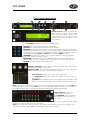
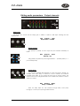
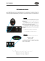
Front panel description
2
3
8
1
10
13
15
12
4
6
5
7
9
11
14
[1]-LCD Screen: Shows, by default, the
name of the last recalled memory on the
bottom line of the screen, and the current
routing on the top line. Also used to show
all parameters as they are edited, and all
menu selections.
Control Keys: Selection and adjustment of parameters.
[2]-NEXT key moves forward through list of parameters.
[3]-BACK key moves backwards through list of parameters.
[4]-MENU key activates the main menu – a second press selects the last menu edited – a
third press selects the last menu item. In this way, three presses on MENU from the default
screen will jump back to the last parameter adjusted. Selection of different menus is
accomplished using the BACK and NEXT keys, or with the FREQ encoder.
[5]-ENTER key enters the chosen menu, confirms selections, and changes filter
types when editing parametric sections.
[6]-BYPASS will flatten the currently selected parametric sections. Note that, for
safety reasons, it is not possible to bypass the high and low pass filter sections.
[7]-QUIT exits menus back to the default screen.
[8]-Rotary Encoders: Three velocity sensitive encoders adjust the relevant
parameters as displayed on the screen.
[9]-Status LEDs: The two status LEDs show, from left to right, AES inputs
selected (flashing if not locked), and AES outputs selected.
Input Sections: Control and monitor input signal paths.
Red [10]-MUTE buttons illuminate when pressed and mute audio for
that channel.
[11]-EDIT buttons illuminate yellow when pressed, and access gain on first
press, then last viewed parameter on second press, then exit on third press.
[12]- Input meters show dB from clipping point of the analogue to digital converters. Yellow (0dB) LED
illuminates 3dB from clipping. Red CLIP LED may illuminate independently from the rest of the meter to
show digital overflow. All four CLIP LEDs illuminating indicates internal clipping after the ADC.
Output Sections: Control and
monitor output signal paths.
Red [13]-MUTE buttons illuminate
when pressed and mute audio for
that channel.
[14]-EDIT buttons illuminate yellow when pressed, and access gain on first press, then last viewed
parameter on second press, then exit on third press.
[15]-Output meters show dB from limiting. The yellow LED illuminates at the onset of limiting. The
red LED illuminates at 4dB, ‘L+4’, into limiting (i.e. 4dB of gain reduction).
4
User’s Manual
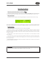
DSP-2060A
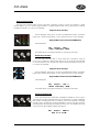
Rear panel description
1
2
3
4
5
6
[1]:
Power Switch: turns the unit’s mains supply off and on.
Mains Fuse: located in a finger-proof holder adjacent to the mains inlet. A
spare fuse is also located in this holder.
Mains Inlet: connected via a standard IEC socket.
[2]-RS232: RS232 standard via a 9 pin D-type connector, for connection to a
PC. Data is converted to RS485 standard and relayed to slave units via the
RS485 sockets.
[3]-RS485 IN-OUT: XLR sockets. Used for transmission of remote control
data over long distance or multiple unit applications. See page 18 for more
information.
[4]-Audio Outputs: 3 pin XLR sockets are provided for each channel. All are fully balanced, pin 2 hot, 3
cold, 1 screen. Note the legending on the panel to designate which outputs are used for AES streams when
the digital outputs are enabled. Please see page 23 for more information.
[5]-AES Input Switch: Recessed switch to select AES
digital inputs. Red LED will illuminate in the hole when
AES inputs are selected, along with the corresponding
front panel indicator.
[6]-Audio Inputs: 3 pin XLR sockets are provided for each channel. All are fully balanced, pin 2 hot, 3 cold,
1 screen. Note the legending on the panel to designate which inputs are used for AES when the digital inputs
are enabled. Please see page 23 for more information.
WARNING:
Class I device. This equipment must be earthed. If the cable or the mains plug
are damage they must replaced.
Always replace the fuse with the correct type and rating as shown on the rear
panel legend.
User’s Manual
5
DSP-2060A
Operating the device
Note about operation with AudioCore software:
The following operating information covers setup and control of the DSP-2060A via the front panel controls
only. Please consult the manual supplied with this software for information regarding full computer control.
Start-up procedure
Switching on the unit will display a brief message detailing the unit type and software version running
and all LEDs will briefly illuminate. The unit will then begin its countdown to the wake-up procedure, during
which time the audio will fade up to the level last set. Metering will begin to operate when the fade-up starts.
Preliminary Set-up
The procedure below should be followed when first installing a DSP-2060A.
Design your crossover! To do this, press MENU, and use the BACK or NEXT key to select 'Crossover
sub-menu' and then press ENTER. Use the BACK or NEXT key to select 'Design a crossover' and then
press ENTER. Finally, use the BACK or NEXT key to select the desired routing and follow the set-up wizard
to finalise your design.
Note that when in a menu, ENTER is always used to confirm selections. The current selection is marked
with an asterisk '*'.
Use the EDIT keys on each output channel with the BACK and NEXT keys to select the high pass filters,
low pass filters, parametrics etc. Note that when designing a new crossover, the high and low pass filters will
be set to default values.
Use the EDIT keys on each input channel with the BACK and NEXT keys to select the gain, delay and
parametrics available on each input.
Information:
Note that if no action is taken in menu mode, the unit will return to normal 'default' mode after about
twenty (20) seconds. Repeat the above directions to return to menu mode.
6
User’s Manual
DSP-2060A
Routing Options and Processing Blocks
Due to the completely new DSP platform, the routing possibilities within the DSP-2060A has been made
completely flexible, with a matrix available allowing any combination of inputs to be routed to any output. The
additional DSP power has permitted the inclusion of more processing blocks, even considering the extra
inputs and outputs, and the doubling of sample rate.
To reduce set-up time and aid usability, several standard configurations are available as described in a
later section.
This section will outline the processing blocks available in relation to the signal path, and explain the
various options for routing, including the “Free Assign” mode, which opens up completely flexible channel
routing.
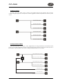
Input Channel Makeup
The diagram below shows the processing available on each of the two input channels, before routing to the
matrix.
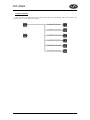
Output Channel Makeup
The diagram below shows the processing available on each of the six output channels, after routing from
the matrix.
Preset Routing Configurations
In addition to the ability to assign any combination of inputs to any output, a number of preset
configurations are provided, for use when designing a crossover from scratch. These have the advantage of
suggested settings for the high and low pass filters to useful basic starting points, to filter the different
outputs as appropriate for the chosen configuration. These may, of course, be freely modified afterwards
should they not suit the requirements exactly.
The diagrams on the following pages show the connections made between inputs and outputs, and the
suggested values chosen for the high and low pass filters.
User’s Manual
7
DSP-2060A
2 x 3 way crossover:
As shown, each input feeds a pair of outputs, odd numbers being the low frequency split, and even
numbers being the high part of the spectrum. Default suggested crossover frequencies are shown by each
output.
2 x 2 way crossover + Mono:
This format feeds input A to outputs 1 and 2, designated low and high respectively. Input B feeds outputs
3 and 4, low and high respectively. Outputs 5 and 6 are both fed from the sum of input A and B. Output 6 is a
full bandwitch output by default, with output 5 being bandwitdth limited as a sub output.
“LOW” OUTPUT: 40.1Hz - 1.62kHz
Σ
“HIGH” OUTPUT: 1.62kHz - 22.2kHz
“LOW” OUTPUT: 40.1Hz - 1.62kHz
“HIGH” OUTPUT: 1.62kHz - 22.2kHz
SUB: 15Hz - 120Hz
AUX: 10Hz - 32kHz
8
User’s Manual
DSP-2060A
1 x 6 way crossover:
Inputs A is fed to all eight outputs, with initial settings being all full bandwidth, with input B unused. The
crossover points can be adjusted as desired.
User’s Manual
9
DSP-2060A
Free Assign Routing
If none of the preset configurations are appropriate to the required system setup, it is possible to manually
select the routing of the crossover. This is achieved through the ‘Crossover Menu’ -> ‘Design A
Crossover’.
Pressing ENTER will start the crossover design wizard, with the first option being to choose the routing.
The display will show
Design A Crossover ->
Routing = 4 x 2 WAY *
or whatever the current configuration is set to. Press BACK until the display shows
Design A Crossover ->
Routing = Free Assign
And then press ENTER. The EDIT key will illuminate for output 1, as will any relevant input EDIT keys,
showing which inputs are feeding output 1. The display will also detail the current combination of inputs
feeding this output. To change the routing for any output, press its EDIT key, and then choose the required
input channel combination by just pressing the input EDIT keys as appropriate. The input combinations can
also be stepped through in turn by pressing NEXT, or BACK.
To complete the procedure, press ENTER. The wizard will continue, and if the routing has been changed,
all outputs will be muted on exit.
2
Note that:
1st.- Press EDIT to show input routing selection...
2nd.- Press EDIT input keys to select/deselect inputs.
10
User’s Manual
1
DSP-2060A
Editing audio parameters - Input channels
Input gain
The range of the control over the input gain is -40dB to +6dB in
0.1dB steps. Pressing EDIT, the display shows:
IPA
Input A
Gain
Input Gain = +6.0dB
The GAIN allows to change its value. Pressing ENTER to confirm.
Base delay
The maximum available delay between any input and output is 650mS. For
example, if the input delay on channel A is set to 500mS, the maximum
available output delay for any output fed from input A will be 150mS. The
readout units can be changed between time in milliseconds, distance in feet or
distance in metres.
IPA
Input A
Delay
Base Delay = 0.00mS
Note: The delay steps are 1mS (343mm) through FREQ, or 10uS (4mm)
through Q encoder.
Input parametric EQ
The display shows:
IPA
Input A
PEQ : 1 <>
1k00Hz Q=3.0 0.0dB
There are eight bands of parameter equalisation available on every input.
The behaviour of each individual band can be changed to a variety of different
filter shapes, including high and low shelves, notch, and bandpass. Changing
the filter type is achieved by pressing ENTER during editing any particular band.
For more details about the various types of filter available, please see page 32.
User’s Manual
11
DSP-2060A
Editing audio parameters - Output channels
Output gain
The range of the control over the output gain is -40dB to +15dB in 0.1dB steps. Pressing EDIT the
display shows:
OP1
Output 1
Gain
Output Gain = +6.0dB
Output polarity
The polarity (or phase) of each output may be switched individually as
below.
OP1
Output 1
Polar
Polarity = [+]
Using GAIN, the phase may be changed between ‘-’ (inverted phase) or ‘+’
(non inverted phase).
Output delay
The maximum available delay between any input and output is 650mS. For
example, if the input delay on channel A is set to 500mS, the maximum
available output delay for any output fed from input A will be 150mS. The
readout units can be changed between time in milliseconds, distance in feet or
distance in metres.
OP1
Output 1
Delay
Delay = 0.0000mS
Note: The delay steps are 1mS (343mm) through FREQ, 10uS (4mm)
through Q, or 0.3uS (0.1mm) through GAIN encoder.
12
User’s Manual
DSP-2060A
Output high pass filter
The high pass crossover filter on each output has a frequency range of <10Hz up to 32kHz in 1/36th
Octave steps. If you try to set the high pass filter to a higher frequency than the low pass (which would be
pointless and result in no output), the message
‘High/Low Freq. Overlap!’
will be displayed. Note that to access the 48dB/Octave filters, parametric
bands 6 & 7 need to be bypassed, or set to 0dB. If they are not, the message
‘Bypass PEQ’s 6 & 7 To Access 48dB Slopes’
will be displayed.
OP1
Output 1
HPF /~~
<10Hz Linkw-Riley 48dB
The FREQ allows to change the frequency, and using Q the slope.
Output low pass filter
The low pass crossover filter on each output has a frequency range of
35.1Hz up to >32kHz in 1/36th Octave steps. If you try to set the low pass filter
to a lower frequency than the high pass (which would be pointless and result in
no output), the message
‘High/Low Freq. Overlap!’
will be displayed. Note that to access the 48dB/Octave filters, parametric
bands 8 & 9 need to be bypassed, or set to 0dB. If they are not, the message
‘Bypass PEQ’s 8 & 9 To Access 48dB Slopes’
will be displayed.
OP1
Output 1
LPF ~~\
>32kHz Linkw-Riley 48dB
The FREQ allows to change the frequency, and using Q the slope.
Output parametric EQ
There are nine bands of parametric equalisation available on every output.
The behaviour of each individual band can be changed to a variety of different
filter shapes, including high and low shelves, notch, and bandpass. Changing
the filter type is achieved by pressing BYPASS to bypass the filter and then
pressing ENTER during editing any particular band. For more details about the
various types of filter available, please see page 32.
OP1
Output 1
PEQ:1<>
1kHz Q = 3 0.0dB
User’s Manual
13
DSP-2060A
Information:
Note that 2 bands each will be lost when using 48dB slope crossover filters, resulting in
a maximum of 5 bands of EQ when both high and low pass are set to 48dB/Octave.
Output limiter
The limiter on each output has adjustable attack and threshold, with a
release time that is selectable to be a multiplier of the attack time. For example,
as shown below, the attack time is 2mS and release is “x16” so 32mS. The
attack and release times can be automatically linked to the high pass filter
frequency, so that they are set to correct values for the output's frequency
range. If this feature is enabled, the display will show ’Automatic T/C’ in place
of the attack and release times. Selection of automatic time constants is
through the ’Design a Crossover’ wizard, in the ’Crossover Sub-menu’.
OP1
Output 1
Limiter
Atk=2.0mS Rel=x16 +22dB
Using FREQ, the attack time change. Through Q the release time change,
and through GAIN the threshold change. To complete the procedure, press
ENTER.
Output “D-Max” (Clip) limiter
The clip limiter on each output is designed to sit at a threshold just above
the standard limiter and has a look ahead attack so that its threshold can never
be exceeded. The release time can be automatically linked to the high pass filter
frequency, so that it is set to a value appropriate for the output's frequency
range. If this feature is enabled, the display will show ‘Rel.=Auto’ in place of
the release time. Selection of automatic time constants is through the ‘Design
a Crossover’ wizard, in the ‘Crossover Sub-menu’.
More information about the limiters and their use is given in the section on
page 27.
OP1
Output 1
ClipLim
Rel.=Medium 2dB Above
Using FREQ, the release time change, and through GAIN the threshold
change. To complete the procedure, press ENTER.
14
User’s Manual
DSP-2060A
Input ganging and output ganging
The method of linking inputs or outputs together during editing is achieved in the same way, so only
crossover (output) ganging will be explained here. Having selected ‘Crossover Ganging’ from the menu
under the ‘Crossover Sub-menu’, the current ganging set-up will be displayed. This will either be a preset
selection as would be useful in a standard crossover configuration – for example
<-Crossover Ganging
Ganging=1+3+5 2+4+6
…would be a logical ganging arrangement if the crossover was set up as a 3 x 2 way – linking the control
and adjustment of all “Low” outputs together, and that of all “High” outputs together.
However, if the crossover has not been set up with a preset routing configuration, then it may be required
to set up the ganging to compliment this configuration. This is achieved using the ‘Free Assign’ mode. This
is selected from the preset ganging choices, which are:
Ganging=None
Ganging=Free Assign
Ganging=1+2+3+4+5+6
Ganging=1+3+5 2+4+6
[todas las salidas independientes]
[escoja asignación]
[1x6 vías]
[2x3 vías]
Selecting ‘Free Assign’ and then pressing ENTER will begin the process of ganging outputs together
using the following simple rules:
Ø
All outputs are ganged to the lowest number – so to gang 3 & 5, 5 must be selected and then ganged
to 3.
Ø
Outputs cannot share more than one ganging set – so for example output 3 cannot be ganged to 2 and
4 unless they are ganged together as well. (Effectively 3 and 4 are ganged to 2 in this case)
With these rules in mind, selecting and setting up gangs is quite straightforward.
1
Press EDIT keys to gang
flashing channel with selection
EDIT LED will light to show
lowest number in gang
Press MUTE to select
channel to gang...
MUTE begins to flash
2
Press a MUTE key to choose the output to gang – its LED will begin to flash, and an EDIT key will
illuminate to show which output it is currently ganged with. To change this selection, just press another EDIT
key, remembering that gangs work from the highest to lowest number. So, to gang outputs 1 and 5, press
MUTE 5 then EDIT 1 – the display will show
<-Crossover Ganging
Gang Output 5 with 1
Ganging is cleared by selecting ‘Ganging=None’ from the initial choices given above. The ‘Input
Ganging’ procedure is identical to the crossover ganging, selectable under the ‘Input Sub-Menu’.
User’s Manual
15
DSP-2060A
Memory structure
The DSP-4080 has its memories split into sections, allowing independent recall of crossover settings (i.e.
all parameters associated with outputs), and input settings.
There are, therefore, two types of memory available: ‘Input Only’ and ‘Crossover Only’,also
combinations ‘Input & Xover’.
These, and all combinations of memory types, appear in the ‘GLOBAL MEMORY Sub Menu’, and its
operation warrants a little more explanation.
RECALL a Memory
Type= Input & Xover *
STORE a Memory
Type= Input & Xover *
ERASE a Memory
Type= Input & Xover *
Selecting to ‘STORE’ or ‘RECALL’ using the ‘GLOBAL MEMORY Sub Menu’ option offers the
possibility of storing various combinations of the available memory types, and these are selected using the
BACK and NEXT keys.
To explain how this all works, please consider the following example.
There are 10 memories stored in the unit with various combinations of input and crossover memories.
16
User’s Manual
DSP-2060A
Through ‘STORE’ using ‘GLOBAL MEMORY Sub Menu’, we have stored 10 memories.
If it is required to recall a location that contains ‘Input Only’ settings, this will limit the selection as
shown below: 2, 3, 4, 6, 8, 9, and 10.
But, recalling 4, 6, 8 or 10 will leave the current ‘Xover’ settings untouched.
However, if it is required to recall ‘Input & Xover’ settings then 4, 6, 8, and 10 will be the only numbers
available, with the option to change all the parameters.
Note that storage and erasure of memories does not follow quite the same rules, being simpler in its
operation.
Selecting Input and Crossover during a Store will skip any memories that have other combinations in
them.
Selecting Erase for any combination will show only locations that have EXACTLY that combination – it is
not possible to erase just one part of a combination memory.
The DSP-2060A has 256 memory locations, but these are dynamic in nature – obviously a memory
containing Input and Crossover settings takes up more space than one containing just Input settings.
User’s Manual
17
DSP-2060A
Remote control interface operation
RS232 interface
This interface is fitted as standard to all units and is accessed via the 9-pin D-type connector on the rear
of the unit. Note that to connect to a computer's COM (serial) port correctly, a one-to-one cable must be
used, and NOT a 'null modem' cable. A 'null modem' cable has the 'transmit' and 'receive' wires swapped
over and will not work.
The RS232 connection is suitable for distances of about a maximum of 25 feet (7.62 m) between the PC
and the unit. If you experience problems with the connections, consider
?
selecting a slower baud rate
?
selecting the 'Use Acknowledge Cmd' option in AudioCore (see the Remote Menu > RS232
Configuration window)
?
running the unit via the RS485 interface
Note than only one unit at a time may be connected to the computer via this interface. Additional units
may be 'daisy-chained' via the RS485 connections from the back of the first one (it acting as a converter for
them), but their RS232 ports are not used.
RS232 Connection (Single Unit)
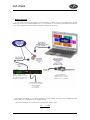
A typical interface set-up might involve running an RS232 link from laptop or a desktop computer to a
DSP-2060A unit set up as a master unit. The diagram below shows this method of connection, the required
menu options are also given. Note that the RS232 cable must be a 1-1 connection type, NOT a null modem
cable (which has connections crossed internally).
Walkabout Pack II KIT
(Please see your manual
available from our website)
9-pin D type 1-1
Male to Female
(NOT null Modem cable)
DSP-2060A
Interface Sub Menu
Mode = RS232 Mode
SERIAL SPEED = 115200
Stop MIDI Prog Chng Yes
Remote ID Number = 1
18
USB-Serial
Converter
(USB-232)
Laptop or Desktop
Running AudioCore.
Remote Menu:
RS232
COM1 to COM12
Baud Rate: 115200
User’s Manual
DSP-2060A
Loading New Software via a PC
The unit's internal software may be updated via the RS232 port ONLY, one unit at a time. We recommend
disconnecting all other devices when updating the software.
The unit's interface must be set as RS232 Master on ID1 for the PC loader program to recognise it and
allow the update to be sent.
RS232 Connection (Multiple Units)
If control over multiple units is required, typically the slaves will be set up to run from the RS485 ports on
the master unit. Note the incremental 'ID NUMBER' option in the unit's interface setup.
DSP-2060A
Interface Sub Menu
Mode = RS232 Mode
SERIAL SPEED = 115200
Stop MIDI Prog Chng Yes
Remote ID Number = 1
DSP-2060A
Interface Sub Menu
Mode = RS485 Mode
SERIAL SPEED = 115200
Stop MIDI Prog Chng Yes
Remote ID Number = 2
DSP-2060A
Interface Sub Menu
Mode = RS485 Mode
SERIAL SPEED = 115200
Stop MIDI Prog Chng Yes
Remote ID Number = 3
User’s Manual
19
DSP-2060A
Shadow ID Numbers
Shadow ID numbers allow extra units to share the same ID and follow the settings of the 'main' ID. This is
useful for larger systems (for example anything above a 4-way stereo system) where it is only necessary to
set up one side of the system, and allow the other unit to track it identically.
Using the shadow IDs in this way also reduces the apparent system complexity within AudioCore. This is
due to the fact that shadow ID's NEVER send back any settings to AudioCore and because of this will NOT
appear in the list of connected units.
They can be thought of as listening to and acting upon all information addressed to them, but not
replying. Up to 128 shadow units may be connected and assigned the same ID as the 'main' unit, but
remember that the maximum total units on any one RS485 network is 128.
RS485 interface
This interface is fitted as standard to DSP2060A units and is accessed via the 3-pin XLR
sockets on the rear of the unit. Cables to connect
units together or to an RS232-485 converter will
need to be wired one-to-one. We recommend the
use of standard shielded microphone cables, or a
balanced feed from a multicore.
DSP-2060A
Interface Sub Menu
Mode = RS232 Mode
SERIAL SPEED = 115200
Stop MIDI Prog Chng Yes
Remote ID Number = 1
Cable ‘01’
DSP-2060A
Interface Sub Menu
Mode = RS485 Mode
SERIAL SPEED = 115200
Stop MIDI Prog Chng Yes
Remote ID Number = 2
Cable ‘02’
RS485 is a fully balanced system, capable of
sending data over distances of up to one
kilometre. Note, however, that this is the total
length of connection. The RS485 output of each
unit is purely hardwired from the input and so no
electrical regeneration of the signal is provided.
What this means is that the distance from the first
RS485 output to the last RS485 input must not
exceed 1km in total.
As this diagram illustrates – The combined
length of cables 01 + 02 + …NN < 1000 metres.
DSP-2060A
Note that this includes any units set up as
shadow IDs.
Interface Sub Menu
Mode = RS485 Mode
SERIAL SPEED = 115200
Stop MIDI Prog Chng Yes
Remote ID Number = 3
Cable ‘NN’
Units may be connected in a star configuration
if required, so a long cable may be used and then
a hub formed with units all connected to this, but
we do not recommend daisy chaining these
configurations together.
DSP-2060A
Interface Sub Menu
Mode = RS485 Mode
SERIAL SPEED = 115200
Stop MIDI Prog Chng Yes
Remote ID Number = NN
20
User’s Manual
DSP-2060A
RS485 connection
To use RS485 communication directly from a computer, a master unit must be configured to receive
RS485. You must have a suitable RS485 port on your computer, or a converter connected to the serial port
in use. This configuration is shown below, along with the required unit setup.
RS232 to RS485
CONVERTER KIT
Part Number
INT-485
DSP-2060A
OR
via wireless with
Walkabout Pack II KIT
(Please see your manual
available from our website)
Interface Sub Menu
Mode = RS485 Mode
SERIAL SPEED = 115200
Stop MIDI Prog Chng Yes
Remote ID Number = 1
Additional DSP-2060As
may be set up as slaves
with incremental
ID numbers
as necessary...
The adapter is available in a kit, which includes an RJ-45 adapter, the XLR to 9-pin adapter, and the
converter itself. This complete kit is part number INT-485.
If you need to make up one of the XLR to 9-pin adapters, the pin-out is:
XLR
1
2
3
D-type
1
3
8
User’s Manual
21
DSP-2060A
If your laptop or PC does not have a spare serial port (or any serial ports for that matter!), the RS485
converter must be connected through a USB – Serial converter. The RS485 converter that DAS recommend
is available in two types – the standard K2, and the more advanced K2-ADE version. Only K2-ADE version
will work with USB-Serial converters, as these converters do not support the extra handshake lines
used with the standard converter.
USB to RS485
CONVERTER KIT
Part Number
USB-485
DSP-2060A
Interface Sub Menu
Mode = RS232 Mode
SERIAL SPEED = 115200
Stop MIDI Prog Chng Yes
Remote ID Number = 1
DSP-2060A
Interface Sub Menu
Mode = RS485 Mode
SERIAL SPEED = 115200
Stop MIDI Prog Chng Yes
Remote ID Number = 2
DSP-2060A
Interface Sub Menu
Mode = RS485 Mode
SERIAL SPEED = 115200
Stop MIDI Prog Chng Yes
Remote ID Number = 3
The adapter is available in a kit, which includes a USB-Serial converter , the XLR to 9-pin adapter, and
the K2-ADE converter itself. This complete kit is part number USB-485.
22
User’s Manual
DSP-2060A
AES inputs and outputs
The DSP-2060A units have a full AES implementation built in as standard. This allows the unit to both
receive digital audio directly, and to transmit digital audio on to other devices. The switching of input and
output can be performed independently, and the inclusion of sample rate converters on the inputs allows the
unit to accept sample rates from 32kHz up to 192kHz.
AES input
Input selection is via a recessed switch on the rear
panel of the unit. A red LED inside this aperture
illuminates to show that the AES digital inputs have
been selected.
A complimentary LED on the front panel also
illuminates. The switch controls the rear panel LED
directly, whilst the front panel one is via the processor,
allowing it to relay a little more information.
If it is flashing, this means that AES inputs have
been selected but have not locked. Once a stable
AES signal is being received, it will be permanently
illuminated.
The AES inputs are marked on the rear panel:
For channels A & B use ‘Input A’
AES output
AES outputs are selected through the AES menu:
AES/EBU Sub Menu
Output Selection
Pressing ENTER and then using BACK and NEXT
chooses either ‘Analogue’ or ‘Digital’. Press ENTER
again to confirm selection.
The AES outputs
Channels
Channels
Channels
are marked on the
1 & 2 use ‘Output
3 & 4 use ‘Output
5 & 6 use ‘Output
User’s Manual
rear panel:
1’
3’
5’
23
DSP-2060A
AES diagnostics and status information
Also under the AES/EBU Sub Menu is the AES Status Information option, which can be used to check
the incoming sample rate(s) and confirm that the data is being received correctly.
Pressing ENTER will first show
AES Device Status
V1: E V2: A
This display shows the correct operation of the two AES transmitters V1 and V2. The letter after each is
the silicon version (and is of no importance to the user).
Pressing ENTER again will show
AES Device Status
V: 96k0
This display shows the status of the AES receiver, input A. The sample rate the unit has been able to
lock to is shown, or UNLOCKED will be displayed in its place. The unit will lock to sample rates from 32kHz
up to and including 192kHz.
The unit's own processing sample rate is 96kHz, and AES output data is always at 96kHz. Internal
sample rate converters will translate all incoming rates to 96kHz – one converter for each AES input.
24
User’s Manual
DSP-2060A
Security and locking
After selecting the Security Sub Menu and pressing ENTER, select one of the lock types, choosing the
most appropriate one for your application. As ever, ENTER will confirm your selection.
User Specific
Upon pressing ENTER to select this type of lock, each parameter group is presented in turn. Choose the
type of lock (as above) using the FREQ encoder, and press ENTER to confirm each parameter. After the last
parameter, the unit requests a password. The description of this operation is given at the end of this section.
This option allows the user to specify, for each type of parameter, whether it is to be completely
accessible ('No Lock'), viewable but not adjustable ('Control'), or effectively unavailable ('Display'). The ability
to operate mutes, store or recall memories, or even access the menus may also be locked.
Xover Only
All input parameters are available, but only the gain trim (+ 6dB) is available on the outputs, effectively
locking all the crossover settings. All mutes remain active.
Xover + Trim
All input parameters available, but no output parameters – the crossover sections are completely locked.
All mutes remain active.
Xover + Trim + Mute
As for 'Xover + Trim' but additionally, output mutes are locked. Input mutes remain active.
Changes Only
All parameters may be viewed, but none may be adjusted. This applies to both inputs and outputs. All
mutes remain active.
Changes + Views
No parameters are accessible – in effect the EDIT keys do nothing. All mutes remain active.
Changes + Mutes
All parameters may be viewed, but none may be adjusted. This applies to both inputs and outputs. All
mutes are also locked.
EVERYTHING
No parameters are accessible – in effect the EDIT and MUTE keys do nothing.
Entering the Password to Complete the Locking Operation
After selection of the lock type from the list above, a four-digit security code will be asked for. This can be
entered by using the FREQ control to select a character, and the BACK and NEXT keys to move to the next
character.
Alternatively, the EDIT keys can be used to enter a code by pressing any combination of the eight
buttons. Each EDIT key represents its channel labelling, so any combination of A, B, 1, 2, 3, 4, 5 and 6 can
be used as a code, as shown below. Press ENTER to accept code and then re-enter it to confirm.
A B
1 2 3 4 5 6
Note:
To prevent external computer control being used to adjust locked settings, be sure to
set the external interface to OFF before locking out the unit.
User’s Manual
25
DSP-2060A
Unlocking the Unit
To unlock the unit press ENTER and then type the code in. This can be entered by using the FREQ
control to select a character, and the BACK and NEXT keys to move to the next character. Alternatively, the
EDIT keys can be used to enter a code by pressing any combination of the eight buttons. Each EDIT key
represents its channel labelling, as described in the locking section.
Forgotten the Password?
Don't panic! Your unit can still be unlocked. In an attempt to improve the security system on the DSP2060A, and prevent a standard master password from becoming common knowledge, the units now have a
random password key generator.
The procedure for unlocking a unit using the password override is explained below:
Switch the unit on with the MENU key held in momentarily. After a few seconds, the unit will ask for a
security code. Use the EDIT keys in the same manner as for entering lock codes (see page 25 for details)
and enter 2121.
The display will show:
Enter XTA Supplied Code:
Break Code = 12345 [NNNN]
The Break Code (in the example 12345) should be noted and supplied to DAS. We have software to
generate the corresponding Pass Code which should be typed in, followed by ENTER. This will unlock the
unit and wipe the previous password.
Note the following about this procedure:
Once the Break Code has been noted, do NOT press MENU again during the operation of the unit
(except to get back to this point on power up), or a different code will be generated. The unit may be used as
normal, but every press of MENU will change the Break Code, so the Pass Code we provide will not work!
The unit may be switched on and off as necessary – just be sure NOT to press MENU, or the entire Break
Code procedure will have to be repeated.
26
User’s Manual
DSP-2060A
Advanced audio features
Program Limiter
High performance digital limiters are provided for each output with control over attack time, release time
and threshold parameters - see details below. This level of control allows the user to balance the required
subjective quality of the limiter against the driver protection requirements. It does also mean that an
incorrectly set limiter may sound awful! In particular, as with all limiters, using too fast an attack or release
time will result in excessive low frequency distortion. In the Design a Crossover sub-menu there is an option
for automatic limiter time constants. Use this option if you are unsure how to set the time constants manually.
We recommend the use of the automatic setting.
In this mode the time constants will be automatically set from the High-Pass filter frequency according to
the table below.
The time constants are set by the high pass filter frequency for that channel.
User’s Manual
27
DSP-2060A
“D-Max” Clip Limiter
The main limitation with traditional dynamics control is the inability of the processing to react truly
instantaneously to the signal. One of the most significant advantages of digital signal processing over
analogue is the ability to delay the audio signal precisely and without extensive complex hardware. The entire
domain of digital signal processing is based around the combination of delaying, multiplying, and
accumulating numbers (representing samples of audio) to implement all the filters and dynamics processing
we have come to expect today.
In the case of dynamics processing, being able to delay a signal allows the processor module to delay the
main signal in relation to the sidechain (the signal being monitored relative to the threshold), so that it can
compensate for peaks prior to the arrival of the main signal.
Consider the situation of a monitor engineer listening to a band perform. Having no access to dynamics
processors, he has had to resort to manually 'riding the faders' in an attempt to keep control of the levels.
Should the level of one of the channels on his desk reach an unacceptably high level, he will turn it down
appropriately.
There is a hidden sidechain in
operation even in this case. The
main signal path is fed through
the monitor desk and the gain
controlled by adjusting the fader.
The sidechain is formed by the
feedback path between the
engineer's ears checking the level
and his brain instructing his hand
to turn the fader down if the
volume goes over the threshold
he has chosen.
In this case, the delay between the signal actually going over the threshold, the engineer registering the
situation, and then turning the signal down will be in the order of several hundred milliseconds at best. This
will only be true if he is not distracted – in reality, it may be several seconds before any gain reduction is
imposed on the signal to bring it under control.
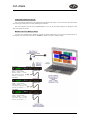
For an analogue dynamics processor, the situation is
much better. Controlling the gain electronically, and not
relying on a human sidechain feedback mechanism, it
can react much more quickly.
The red waveform represents the input to the
dynamics module, with the dotted line showing the
threshold for gain control to occur. There are several
peaks towards the start of this signal that are above the
threshold, and so the dynamics processing should react
to these as appropriate. (In this case reduce the gain).
The blue waveform shows the output of the
dynamics module. The circled peak demonstrates that
the processor has missed the first peak above the
threshold (as it is very fast and short), but has 'caught
up' shortly afterwards, keeping all other peaks under
control. As it is unable to predict what is coming, this
will always be a failing with analogue dynamics
processing.
28
User’s Manual
DSP-2060A
The DSP-2060A's “D-Max” limiter predelays the
sidechain signal, resulting in a “zero overshoot” limiter,
which is able to catch all peaks and provide a reliable
absolute maximum setting for the output of any
channel.
The predelayed sidechain is shown in green, with
the main signal in red. As the main signal arrives slightly
after the sidechain, the output from the unit does not
suffer from the overshoot problem.
Remember that this delay is only in the order of
tens of uS, and is a predelay – the sidechain is moved
back in time in relation to the main signal. Inserting a
delay into the main signal path of an analogue dynamics
processor will achieve similar results, but with the
penalty of delaying the main signal by the amount of
look ahead delay introduced.
The “D-Max” limiter which appears in output lists just following the traditional limiter, has only two
parameters to adjust:
Op1 Output 1 ClipLim
Rel. = Medium 10dB Above
The release time (either Fast, Medium, or Slow) and the threshold. Note that the threshold is set to be a
minimum of 2dB above the threshold of the program limiter – setting the threshold to 10dB Above, as in the
example, means that no more than 10dB of overshoot above the threshold of the program limiter will ever be
allowed.
The release time may also be set to follow the High Pass filter of the output – this is achieved through the
Design a Crossover sub-menu, and will result in the display changing to show
Op1 Output 1 ClipLim
Rel. = Auto 10dB Above
User’s Manual
29
DSP-2060A
Setting Accurate Limiter Thresholds
The limiters built into the DSP-2060A are intended to be used for loudspeaker driver protection, as
opposed to amplifier protection. All modern professional power amplifiers designed for live sound use have
their own limiters, which are tailored to protecting the amplifier from clipping.
The following section describes how to set up the units' limiters to provide exceptional protection against
driver overheating, and cone over-excursion.
Most speaker systems are given a power rating in Watts RMS. This is the maximum continuous power
that the system will handle and often appears very conservative. In reality, as music program is far from
continuous in nature, the peak power of the system is much higher – up to ten times the continuous figure.
Any limiter, which is to protect the driver from damage, must be able to fulfil the following tasks.
?
Have an attack time which is calculated to allow transients through but keep the RMS level below the
speaker manufacturer’s specification;
?
Have a release time which is sufficiently long to avoid the limiter itself modulating the program;
?
Be intelligent enough to adjust the envelope of the limiter according to the frequency content of the
program material.
The program limiters are capable of performing all these tasks. The only parameter that the user must set
manually is the threshold, and it is crucial that this is done correctly. Consider the table below.
Using this table it is a straightforward procedure to work out the required setting of the limiter thresholds
for the system.
?
First, check the RMS power rating of the speaker system, and its impedance.
?
Look up this value in the table above, using the closest value below the rated power of the speaker
system. Note the corresponding 'dB' value.
?
Check the gain of your amplifier, which needs to be in 'dB'.
?
Subtract FROM this gain figure that obtained from the table to find the required absolute setting for the
limiter thresholds.
Note that, for safety, always set the limiter threshold 1 or 2 dB below the maximum allowable worked out
using the above method.
Alert:
ALWAYS REFER TO D.A.S. FOR LIMITER SETTINGS.
30
User’s Manual
DSP-2060A
Crossover Filter Slopes
It should also be noted that the turnover frequency displayed on the screen is the -3dB point for all types
except Linkwitz-Riley where the -6dB point is shown. If the -6dB point is to be used for the Bessel or
Butterworth filter, take the required crossover frequency, multiply this by the appropriate factor from the
following table and then select the closest available frequency on the display.
Please note that unlike conventional analogue crossovers, crossover points and slopes are set with
absolute accuracy since component tolerance problems do not occur.
Please see page 12 for details of how to adjust the high and low pass crossover filter settings.
Time Alignment
A further advantage of the DSP-2060A over conventional products is the provision of an independently
adjustable delay section for each output. This allows the true arrival time from multiple drivers to precisely
aligned rather than relying on the compromise 'phase adjust' approach. Delay time is adjustable in 0.3uS
steps (0.1mm).
Please see page 12 for details of how to adjust the delay times.
To convert from units of time (i.e. milliseconds) to units of distance use the following formula:
1 millisecond = 343mm (1.126ft) @ 20Cº (68Fº)
To calculate time delay for a known distance, use:
Time delay = Distance (in metres)
20.06 x √
273 + ºC
where ºC is the temperature in ºC.
To simplify this equation at 20Cº.
Delay (in mS) = 0.955 x Distancia (in feet)
(Distance in metres x 2.192) or (Distance in feet x 0.955)
Note: [ºC] = 0.5555 x ([ºF]-32)
User’s Manual
31
DSP-2060A
Parametric Filter Types and Their Uses
A wide selection of filter types has been made available under the PEQ section when editing input or
output filters. Scrolling through the various filter types is achieved by repeated presses of the ENTER key.
Note that this will only change filter types if the filter is BYPASSED or the GAIN set to 0dB. Bypassing the
filter, then changing types using the ENTER key will automatically set the gain back to 0dB.
Each filter type will be explained in turn in the following section.
<- Standard Parametric EQ
InA Input A PEQ:1<>
1k00Hz Q = 3.0 0.0dB
The standard parametric band has adjustable frequency, 'Q' (or Bandwidth) and Gain controls. These
affect a range of frequencies symmetrically about the centre freqency as shown in the graph.
Various levels of cut and boost are shown to the left, along with various 'Q' settings (gain boosts only are
shown below). Remember that 'Q' is 1/Bandwidth, so the higher the 'Q', the lower the Bandwidth, and the
smaller the range of frequencies affected.
32
User’s Manual
DSP-2060A
<- Shelving EQ (High Shelf shown)
InA Input A HSF:1-<::
1k00Hz Q = 3.0 0.0dB
Remember – to change filter types, press BYPASS to bypass the filter, and then use ENTER to select the
filter type.
The shelving EQ has adjustable frequency, 'Q' (or Bandwidth) and Gain controls. These affect a range of
frequencies from the turnover freqency as shown in the graph. For a high shelf, frequencies above the
turnover frequency will be affected. For a low shelf, frequencies below the turnover frequency will be affected.
Remember that 'Q' is 1/Bandwidth, so the higher the 'Q', the lower the Bandwidth, and the smaller the
range of frequencies affected.
<- Creating a Flat-topped EQ Response
To create a flat-topped EQ filter response such as that shown to the left, use two EQ bands, BOTH
configured as low shelves. For an overall BOOST, set the Lower frequency filter to BOOST the desired
amount, and the Upper frequency filter to CUT by the same amount.
This example shows one filter at 100Hz and the other at 2kHz, with the 100Hz filter at –10dB, and the
2kHz filter at +10dB. Varying the 'Q' affects the slope of the response – values above 0.75 will cause
overshoot as shown.
Assymetrical responses may be achieved by adjusting the 'Q' of each filter independently.
User’s Manual
33
DSP-2060A
<- Low/High pass variable ‘Q’ filter (low pass shown)
InA Input A LPF:1~~\
1k00Hz Q = 3.0 LPF VarQ
Remember – to change filter types, press BYPASS to bypass the filter, and then use ENTER to select the
filter type.
The low and high pass variable 'Q' filters have adjustable frequency and 'Q' (or Bandwidth) controls. The
'Q' control adjust the damping of the filter, so that low 'Q' settings show less overshoot at the turnover
frequency, but also slower roll-off.
Remember that 'Q' is 1/Bandwidth, so the higher the 'Q', the lower the Bandwidth, and the smaller the
range of frequencies affected. The filter is primarily 12dB/Octave, but in achieving this sort of roll-off with a
high 'Q' value will result in quite a large overshoot in level at the turnover frequency. This type of filter is often
also called a resonant filter.
34
User’s Manual
DSP-2060A
Specifications
Inputs: 2 electronically balanced
Impedance: > 10k ohms.
CMRR : >65dB 50Hz - 10kHz.
MUTE : ON/OFF
Outputs: 6 electronically balanced
Source Imp: < 60 ohms
Min. Load: 600 ohms
Max. Level: +20dBm into 600 ohms
MUTE : ON/OFF
Frequency Resp.: ±½dB 20Hz-20kHz
-3dB @ 32kHz
Dyn. Range: >116dB 20Hz-20k unweighted
Distortion: < .02%@1kHz,+18dBm
Maximum Delay: 650 mS
Min Step Size: 0.3uS
Input Gain: +6dB to -40dB in 0.1dB steps
Output Gain: +15dB to -40dB in 0.1dB steps
Limiters
Program Limiter:
Threshold: +22dBu to -10dBu
Attack time: 0.3 to 90 milliseconds
Release time: 2/4/8/16/32 x Attack time
“D-Max” Limiter:
Attack Time: -60uS
Release Time: Slow/Medium/Fast
Display: 2 x 24 Character LCD
Input meter: 2 x 4 point, -24dB to digital clip
Output meter: 6 x 4 point, -24dB to +4dB into limit
Parametric Equalisation
8 per Input / 9 Sections per Output
Filter Gain: +15dB to -30dB in 0.1dB steps
Freq. Range: 19.7Hz - 32kHz, 1/36 octave steps
Filter Q / BW: 0.4 to 128 / 2.5 to 0.008
(Sections switched to shelving response)
Low frequency: 19.2Hz - 1kHz
High frequency: 1kHz - 32kHz
Shelf gains: ±15dB in 0.1dB steps
High and Lowpass Filters
Filters: 1 of each per output.
Freq. Range HPF: 10Hz - 16kHz
1/36 octave steps.
Freq. Range LPF: 35Hz - 22kHz
1/36 octave steps.
Responses:
1st Order 6dB/Oct.
Bessel/Butterworth/Linkwitz-Riley 12-24-48dB/Oct.
Bessel/Butterworth 18dB/Oct.
Connectors
Inputs: 3 pin female XLR
Outputs: 3 pin male XLR
External: 9 pin DEE connector (RS232)
RS485: 3 pin male XLR (out) 3 pin male XLR (in)
Power: 3 pin IEC
Power: 60 to 250V ±15% @ 50/60Hz
Consumption: < 30 watts.
Weight: 3.3kg. Net (4.7kg. Shipping)
7.26lb. Net (10.34lb. Shipping)
Size: 44 x 482 x 300 (mm)
1.75"(1U) x 19" x 11.8"
Due to continuing product improvement the above
specifications are subject to change.
Latency: 1.5mS (analogue in – analogue out @ 96kHz)
User’s Manual
35
DSP-2060A
36
User’s Manual
MENU activates menus
LCD display
BACK and NEXT step through
channel parameters & menus
Notes
The crossover (output) settings may be stored
independently of the input settings, using the
Global Memory sub-menu.
The output meters show level, in dB from the
limiter threshold, and the input meters show level
from clipping the A-D converters, pre-gain and all
EQ.
The high and low pass crossover filters are
defined independently on each output channel.
To access the limiter attack and release
parameters, select “AutoLimiter TimeCst: No”
when designing a crossover.
To swap parametric filter units between
bandwidth ('BandW') and 'Q', enter System Submenu, select 'Filter Q / Bandwidth', and select
required readout units.
To swap delay time units, enter System Submenu, select 'Delay Time / Distance', and select
required readout units.
Pressing an EDIT key flashes corresponding
channels routed to / from that channel.
Press QUIT to exit menus
Press ENTER to enter menus
and confirm selections
The Menus and their Contents
GLOBAL
MEMORY
Sub-menu:
Recall/Store/Erase input and crossover settings, or
combinations of.
INPUT SECTION Sub-menu: Set up input
ganging, and GEQ 'Q' setting.
CROSSOVER Sub-menu: Set up or adjust
crossover design, including routing and auto
limiter setting. Also set up output ganging.
INTERFACE Sub-menu: Comms interface
setup (RS232 and RS485), G.P.I. interface
configuration, and wireless interface.
SYSTEM Sub-menu: Used to view unit's
status, and select various global options such as
PEQ 'Q' or bandwidth units, delay units, and
output metering point (pre/post mute).
SECURITY Sub-menu: Used for locking various
operations of the unit, using a 4 digit code.
AES/EBU Sub-menu: Switch outputs from
analogue to digital and monitor AES input status
info. (AES inputs are switched via rear panel).
Press BYPASS to temporarily
flatten parametric EQ sections
Press MUTE to mute channel
Editing channels : press channel's GAIN key.
First press accesses that channel's gain. To scroll
through channel's parameters, use the BACK and
NEXT keys. Second press accesses last viewed
parameter. Third press will drop back to the
default screen.
Accessing menus: press the MENU key. Use
the BACK and NEXT keys to select the sub-menu
required, and enter the sub-menu using the
ENTER key. This applies to all levels of menu.
ENTER always confirms selections.
Press EDIT to access channel gain;
press again to view last section edited;
press again to exit to default screen
Quick reference
D.A.S. AUDIO, S.A.
C/. Islas Baleares, 24
46988 Fuente del Jarro
Valencia, SPAIN
Tel. 96 134 0525
Tel. Intl. +34 96 134 0860
Fax 96 134 0607
Fax Intl. +34 96 134 0607
D.A.S. AUDIO OF AMERICA, INC.
Sunset Palmetto Park
6816 NW 77th Court.
Miami, FL. 33166 - U.S.A.
TOLL FREE: 1-888DAS4USA
Tel. +1 305 436 0521
Fax +1 305 436 0528
UM_DSP2060A_01_EN
www.dasaudio.com
D.A.S. AUDIO ASIA PTE. LTD.
25 Kaki Bukit Crescent #01-00/02-00
Kaki Bukit Techpark 1
Singapore 416256
Tel. +65 6742 0151
Fax +65 6742 0157