1
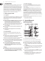
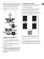
User Manual
EUROLIVE
E1520 /E1220
Processor-Controlled 400-Watt 2-Way PA Loudspeaker/Floor Monitor
2
EUROLIVE E1520A/E1220A User Manual
Table of Contents
Thank you........................................................................ 2
Important Safety Instructions....................................... 3
Legal Disclaimer.............................................................. 3
Limited warranty............................................................. 3
1. Introduction................................................................ 4
1.1 Before you get started....................................................... 4
1.1.1 Shipment........................................................................... 4
1.1.2 Initial operation.............................................................. 4
1.1.3 Online registration........................................................ 4
2. Control Elements and Connections.......................... 4
3. Application Examples................................................ 5
3.1 Using a mixing console...................................................... 5
3.2 Using several E1520A/E1220A loudspeakers............. 5
3.3 Direct connection of a stereo signal source.............. 5
4. Installation.................................................................. 6
5. Specifications.............................................................. 6
Thank you
Thank you for the confidence you have placed in us by purchasing the BEHRINGER
EUROLIVE E1520A/E1220A speaker. Targeting DJs and presenters, these extremely
robust, high-power loudspeakers offer amazing performance, durability and
portability that have made the series of EUROLIVE loudspeakers so widely used
and appreciated.
3
EUROLIVE E1520A/E1220A User Manual
Important Safety
Instructions
Terminals marked with this symbol carry
electrical current of sufficient magnitude
to constitute risk of electric shock.
Use only high-quality professional speaker cables with
¼" TS or twist-locking plugs pre-installed. All other
installation or modification should be performed only
by qualified personnel.
This symbol, wherever it appears,
alerts you to the presence of uninsulated
dangerous voltage inside the
enclosure - voltage that may be sufficient to constitute a
risk of shock.
This symbol, wherever it appears,
alerts you to important operating and
maintenance instructions in the
accompanying literature. Please read the manual.
Caution
To reduce the risk of electric shock, do not
remove the top cover (or the rear section).
No user serviceable parts inside. Refer servicing to
qualified personnel.
Caution
To reduce the risk of fire or electric shock,
do not expose this appliance to rain and
moisture. The apparatus shall not be exposed to dripping
or splashing liquids and no objects filled with liquids,
such as vases, shall be placed on the apparatus.
9. Do not defeat the safety purpose of the polarized
or grounding-type plug. A polarized plug has two blades
with one wider than the other. A grounding-type plug
has two blades and a third grounding prong. The wide
blade or the third prong are provided for your safety. If the
provided plug does not fit into your outlet, consult an
electrician for replacement of the obsolete outlet.
10. Protect the power cord from being walked on or
pinched particularly at plugs, convenience receptacles,
and the point where they exit from the apparatus.
11. Use only attachments/accessories specified by
the manufacturer.
12. Use only with the
cart, stand, tripod, bracket,
or table specified by the
manufacturer, or sold with
the apparatus. When a cart
is used, use caution when
moving the cart/apparatus
combination to avoid
injury from tip-over.
13. Unplug this apparatus during lightning storms or
when unused for long periods of time.
14. Refer all servicing to qualified service personnel.
Servicing is required when the apparatus has been
damaged in any way, such as power supply cord or plug
is damaged, liquid has been spilled or objects have fallen
into the apparatus, the apparatus has been exposed
to rain or moisture, does not operate normally, or has
been dropped.
15. The apparatus shall be connected to a MAINS socket
outlet with a protective earthing connection.
16. Where the MAINS plug or an appliance coupler is
used as the disconnect device, the disconnect device shall
remain readily operable.
Caution
These service instructions are for use
by qualified service personnel only.
To reduce the risk of electric shock do not perform any
servicing other than that contained in the operation
instructions. Repairs have to be performed by qualified
service personnel.
1. Read these instructions.
2. Keep these instructions.
3. Heed all warnings.
4. Follow all instructions.
5. Do not use this apparatus near water.
6. Clean only with dry cloth.
7. Do not block any ventilation openings. Install in
accordance with the manufacturer’s instructions.
8. Do not install near any heat sources such as
radiators, heat registers, stoves, or other apparatus
(including amplifiers) that produce heat.
LEGAL DISCLAIMER
TECHNICAL SPECIFICATIONS AND APPEARANCES
ARE SUBJECT TO CHANGE WITHOUT NOTICE AND
ACCURACY IS NOT GUARANTEED. BEHRINGER,
KLARK TEKNIK, MIDAS, BUGERA, AND TURBOSOUND
ARE PART OF THE MUSIC GROUP (MUSIC-GROUP.COM).
ALL TRADEMARKS ARE THE PROPERTY OF THEIR
RESPECTIVE OWNERS. MUSIC GROUP ACCEPTS NO
LIABILITY FOR ANY LOSS WHICH MAY BE SUFFERED
BY ANY PERSON WHO RELIES EITHER WHOLLY OR
IN PART UPON ANY DESCRIPTION, PHOTOGRAPH
OR STATEMENT CONTAINED HEREIN. COLORS AND
SPECIFICATIONS MAY VARY FROM ACTUAL PRODUCT.
MUSIC GROUP PRODUCTS ARE SOLD THROUGH
AUTHORIZED FULLFILLERS AND RESELLERS ONLY.
FULLFILLERS AND RESELLERS ARE NOT AGENTS OF
MUSIC GROUP AND HAVE ABSOLUTELY NO AUTHORITY
TO BIND MUSIC GROUP BY ANY EXPRESS OR IMPLIED
UNDERTAKING OR REPRESENTATION. THIS MANUAL
IS COPYRIGHTED. NO PART OF THIS MANUAL MAY
BE REPRODUCED OR TRANSMITTED IN ANY FORM
OR BY ANY MEANS, ELECTRONIC OR MECHANICAL,
INCLUDING PHOTOCOPYING AND RECORDING OF ANY
KIND, FOR ANY PURPOSE, WITHOUT THE EXPRESS
WRITTEN PERMISSION OF MUSIC GROUP IP LTD.
ALL RIGHTS RESERVED.
© 2013 MUSIC Group IP Ltd.
Trident Chambers, Wickhams Cay, P.O. Box 146,
Road Town, Tortola, British Virgin Islands
LIMITED WARRANTY
For the applicable warranty terms and conditions
and additional information regarding MUSIC Group’s
Limited Warranty, please see complete details online at
www.music-group.com/warranty.
4
EUROLIVE E1520A/E1220A User Manual
1. Introduction
With powerful 400 Watts, wide frequency bandwidth and extensive dynamic
range, these sound reinforcement speakers deliver truly impressive sound.
The powerful long-excursion drivers crank out big tone in the bottom end and
mid-range, while the state-of-the-art 1" HF drivers deliver crisp and detailed
highs. Each speaker has been optimized for maximum reliability through the
integrated sound processor, ensuring ultimate system control and speaker
protection. The enclosure’s shape not only allows use in an upright position,
but can also be tilted for use as a floor monitor. It also offers a high degree of
durability that can endure even the harshest road conditions.
1.1 Before you get started
1.1.1 Shipment
Your E1520A/E1220A was carefully packed at the assembly plant to assure secure
transport. Should the condition of the cardboard box suggest that damage may
have taken place, please inspect the unit immediately and look for physical
indications of damage.
◊ Damaged equipment should NEVER be sent directly to us. Please inform
the dealer from whom you acquired the unit immediately as well
as the transportation company from which you took delivery.
Otherwise, all claims for replacement/repair may be rendered invalid.
1.1.3 Online registration
Please register your new BEHRINGER equipment right after your purchase
by visiting http://behringer.com and read the terms and conditions of our
warranty carefully.
Should your BEHRINGER product malfunction, it is our intention to have it
repaired as quickly as possible. To arrange for warranty service, please contact
the BEHRINGER retailer from whom the equipment was purchased. Should your
BEHRINGER dealer not be located in your vicinity, you may directly contact
one of our subsidiaries. Corresponding contact information is included in the
original equipment packaging (Global Contact Information/European Contact
Information). Should your country not be listed, please contact the distributor
nearest you. A list of distributors can be found in the support area of our website
(http://behringer.com).
Registering your purchase and equipment with us helps us process your repair
claims more quickly and efficiently.
Thank you for your cooperation!
2. Control Elements
and Connections
◊ Please always use the original packaging to avoid damage due to
storage or shipping.
◊ Never let unsupervised children play with the E1520A/E1220A or with
its packaging.
(3)
◊ Please dispose of all packaging materials in an environmentally
friendly fashion.
1.1.2 Initial operation
Be sure that there is enough space around the unit for cooling. To avoid
overheating, do not place the E1520A/E1220A on top of power amps or near
radiators, etc.
◊ Blown fuses must be replaced by fuses of the same type and rating.
(8)
(7)
(6)
(5)
(4)
(2)
(1)
Please refer to the “Specifications” for further details.
The mains connection is made using the enclosed power cord and a standard IEC
receptacle. It meets all international safety certification requirements.
◊ Please make sure that all equipment is properly grounded at all times.
For your own safety, never remove or disable the ground conductor of
the unit or of the AC power cord.
◊ The sound quality may diminish within the range of powerful
broadcasting stations and high-frequency sources. Increase the
distance between the transmitter and the device and use shielded
cables for all connections.
Warning
◊ This loudspeaker is capable of producing extreme volumes. Please keep
in mind that high sound pressures do not only temporarily damage
your sense of hearing, but can also cause permanent hearing damage.
Be careful to select a suitable volume at all times.
Fig. 2.1: Control elements and connections (E1520A and E1220A)
(1) Use this 1/4" stereo jack to connect a signal source that has 1/4" output.
(2) Use this XLR connector to connect a signal source that has XLR output.
◊ Always use either the XLR or the ¼" jack input, and use the LEVEL
control ( 4 ) to adapt the input sensitivity. Never use both inputs at the
same time!
(3) The LINK OUTPUT is directly connected to the inputs of the E1520A/E1220A
and carries the input signal with no processing applied. In this way, you can
route the signal to the input of another device (for example, a second
E1520A/E1220A).
(4) To set the volume of the LINE or MIC signal, use the LEVEL control. The left
half of the control range is for attenuating the LINE signal. The right half is
for raising the level of the MIC signal.
(5) The CLIP LED lights up when signal distortion occurs. Reduce the volume
with the LEVEL control until the CLIP LED does not light up any more,
or occasionally lights up at signal peaks.
5
EUROLIVE E1520A/E1220A User Manual
◊ We would like to draw your attention to the fact that extremely loud
sound levels may damage your hearing as well as your headphones/
loudspeakers. Turn the LEVEL control fully to the left before you switch
on the unit. Be careful to select a suitable volume at all times.
3. Application Examples
◊ Turn the LEVEL control fully to the left before you switch on the unit
with the POWER switch. Then, raise the volume to a suitable level.
(6) The HIGH control adjusts the level of the high-frequency range.
3.1 Using a mixing console
(7) The PWR LED lights up when the loudspeaker is put into operation.
A common way to use 2 E1520A/E1220A loudspeakers is with a mixing console.
In this case, connect each of the main outputs that are on the mixing console
to a E1520A/E1220A loudspeaker. The E1520A/E1220A includes XLR and 1/4"
connectors. To avoid interference, use only XLR or 1/4" jack cables.
(8) The LOW control adjusts the level of the low-frequency range.
3.2 Using several E1520A/E1220A loudspeakers
EUROLIVE E1520A
Input
Input
Link Output
Link Output
(9)
Input
(10)
Input
Output L
Output R
(12)
(11)
X2442USB
Fig. 3.1: Wiring several E1520A/E1220A loudspeakers using the LINK OUTPUT connector
Fig. 2.2: Control elements and connections (E1520A and E1220A)
(9) The mains connection is established using a cable with an IEC mains
connector. This cable is packaged with the E1520A/E1220A. To avoid
ground-loop hum, loudspeakers and mixing consoles should be connected to
the same power circuit.
(10) You can replace fuses at the FUSE SWITCH of the E1520A/E1220A.
Always replace fuses with the same type. Please follow the instructions
given in chapter 5 “Specifications.”
(11) Press POWER to turn on your E1520A/E1220A.
◊ The POWER switch does not fully disconnect the unit from the mains.
To disconnect the unit from the mains, pull out the main cable plug
or appliance coupler. When installing the product, ensure the plug
or appliance coupler is readily operable. Unplug the power cord
completely when the unit is not used for prolonged periods of time.
(12) SERIAL NUMBER.
For larger rooms, you can connect several E1520A/E1220A speakers using the
LINK OUTPUT connector (3) (see fig. 3.1).
3.3 Direct connection of a stereo signal source
When you use two E1520A/E1220A loudspeakers, you can directly connect one
stereo signal source, for example, a CD player. In this case, each of the speakers is
connected to 1 signal-source output. (If necessary, use the appropriate adaptor.)
6
EUROLIVE E1520A/E1220A User Manual
4. Installation
Both audio inputs of the BEHRINGER E1520A/E1220A and the LINK OUTPUT
connector are fully balanced. To maximize interference compensation, try to
establish balanced connections to other equipment, whenever possible.
Balanced ¼" TRS connector
strain relief clamp
sleeve
ring
tip
sleeve
ground/shield
ring
cold (-ve)
tip
hot (+ve)
For connection of balanced and unbalanced plugs,
ring and sleeve have to be bridged at the stereo plug.
5. Specifications
Output Power
Low-Frequency Range
RMS @ 1% THD
200 W @ 8 Ω
Peak power 320 W @ 8 Ω
High-Frequency Range
RMS @ 1% THD
50 W @ 8 Ω
Peak power 80 W @ 8 Ω
Input
XLR Connector (Servo-Balanced)
Sensitivity
-40 to +4 dBu
Input impedance
24 kΩ
¼" Jack (Servo-Balanced)
Fig. 4.1: 1/4" TRS connector
Balanced use with XLR connectors
2 1
3
Sensitivity
-40 to +4 dBu
Input impedance
24 kΩ
Link Output
XLR Connector
input
1 = ground/shield
2 = hot (+ve)
3 = cold (-ve)
1
2
3
output
For unbalanced use, pin 1 and pin 3
have to be bridged
System Data
E1520A
Frequency range
50 Hz to 20 kHz
Crossover frequency
2 kHz (12 dB)
Maximum sound pressure level
125 dB @ 1 m
Limiteroptical
Fig. 4.2: XLR connector
◊ Make sure that only competent personnel install your E1520A/E1220A.
They must be sufficiently earthed during and after the installation
process. Otherwise, electrostatic discharges may negatively affect the
operating characteristics of your equipment.
Dynamic Equalizer
Processor-controlled
E1220A
Frequency range
60 Hz to 20 kHz
Crossover frequency
2.2 kHz (12 dB)
Maximum sound pressure level
124 dB @ 1 m
Limiteroptical
Dynamic Equalizer
Processor-controlled
7
EUROLIVE E1520A/E1220A User Manual
Equalizer
HIGH
12 kHz / ±15 dB
LOW
80 Hz / ±15 dB
Power Supply
Mains Voltage / Fuses
100 -120 V~, 50/60 Hz
T 5,0 A H 250 V
220 -230 V~, 50/60 Hz
T 2,5 A H 250 V
Power consumption
max. 400 W
Mains connector
Standard IEC receptacle
Dimensions / Weight
E1520A
Dimensions (H x W x D)
approx. 25.2 x 18.3 x 19"
approx. 640 x 465 x 485 mm
Weight
approx. 58 lbs / 26.3 kg
E1220A
Dimensions (H x W x D)approx. 585 x 400 x 410 mm
(23 x 15.7 x 16.1")
Weight
approx. 22.3 kg (49 lbs)
BEHRINGER is constantly striving to maintain the highest professional standards. As a result of these efforts,
modifications may be made from time to time to existing products without prior notice. Specifications and
appearance may differ from those listed or illustrated.
We Hear You