1
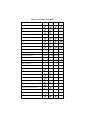
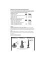
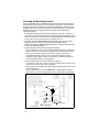
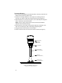
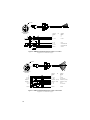
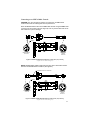
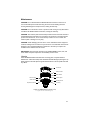
Owner’s Guide & Installation Instructions
WeatherStation Instrument
®
Models:
200WX
150WX
110WX
100WX
U.S. Patent No. 8,326,561
UK Patent No. 2 460 158
Record the serial number found on the underside of the WeatherStation® Instrument.
Serial No._______________Date of Purchase_________________
17-461-01 rev.08
06/12/14
Copyright © 2008 - 2014 Airmar Technology Corp. All rights reserved.
All Rights Reserved. Except as expressly provided herein, no part of this manual may be
reproduced, copied, transmitted, disseminated, downloaded, or stored in any storage
medium, for any purpose without prior written consent of Airmar. Airmar hereby grants
permission to download a single copy of this manual and of any revision of this manual onto
a hard drive or other electronic storage medium to be viewed and to print one copy of this
manual or any revision hereto, provided that such electronic or printed copy of this manual
or revision must contain the complete text of this copyright notice and provided further that
any unauthorized commercial distribution of this manual or any revision hereto is strictly
prohibited.
Information in this manual is subject to change without notice. Airmar reserves the right to
change or improve its products and to make changes in the content without obligation to
notify any person or organization of such changes. Visit the Airmar website at
www.airmar.com for current updates and supplemental information concerning the use and
operation of this and other Airmar products.
Table of Contents
Introduction & Features.............................................................4
Functions & Outputs................................................................. 5
Safety Instructions.................................................................... 6
Importance of True Wind......................................................... 7
Adding External Sensors.......................................................... 7
Hardware.................................................................................. 8
Tools & Materials..................................................................... 9
Where to Purchase Parts........................................................... 9
Choosing the Mounting Location............................................. 10
Installing................................................................................... 11
Cable Routing & Connecting Guidelines................................. 14
Connecting to an NMEA 0183 Display.................................... 15
Connecting to an NMEA 2000® Network............................... 17
Calibrating the Compass........................................................... 18
Maintenance..............................................................................19
Installing the Humidity Sensor................................................. 20
Software.................................................................................... 20
Troubleshooting........................................................................ 21
Technical Information............................................................... 22
Acronyms & Glossary...............................................................23
IMPORTANT: Please read the Owner’s
Guide completely before proceeding.
Introduction
Thank you for purchasing Airmar’s ultrasonic, WeatherStation Instrument. This
exciting product has multiple sensors in a single unit—without any moving parts.
The compact housing is waterproof with a single removable cable. Functions and
features vary by model.
Features
•
•
•
•
Waterproof housing and cable system
Fast response time and update rate
Stable and accurate true wind and heading data in dynamic conditions
Can be programed to compensate for an installation that is not aligned to the
front of the boat/vehicle and/or level
• Can be calibrated to compensate for magnetic deviation caused by ferrous
metals and other electro-magnetic fields
• GPS with WAAS and EGNOS
4
Table 1: Functions & Outputs
200WX
150WX
110WX
100WX
Optional
Optional
Optional
Relative humidity
Optional
Optional
Optional
Dew point temperature
Optional
Optional
Optional
Heat index temperature
Optional
Optional
Optional
NMEA 0183: RS232
Optional
Optional
Optional
Optional
NMEA 0183: RS422
Optional
Optional
Optional
Optional
Apparent wind speed and angle
True wind speed and direction
True wind speed relative to water
Heater to keep wind channel free of ice
Air temperature
Apparent wind chill temperature
True wind chill temperature
Barometric pressure
Rain intensity
Rain accumulation
Rain event duration
Peak time of rain intensity
3D Magnetic compass heading
2D Magnetic compass heading
Heading relative to true north
Rate of Turn
Angle of pitch and roll
Rate of pitch & roll
Global Positioning System (GPS)
NMEA 2000®: CAN
5
WARNING
Navigation Aid Only—The WeatherStation Instrument is
only an aid to navigation and should never be solely relied
upon. It is not a replacement for traditional navigation aids
and techniques. Only official government charts contain all
the information needed for safe navigation.
Follow the safety precautions below to reduce the risk of poor product
performance, property damage, personal injury, and/or death.
WARNING: Correct Installation Important
The WeatherStation Instrument must be installed and operated according to the
instructions in this owners guide.
WARNING: Installation Safety
Always wear safety goggles and a dust mask when installing.
WARNING: Compass Safe Distance
The WeatherStation Instrument must be a minimum of 0.3m (1') from other
standard and steering compasses.
WARNING: Do Not Install Near Artificial Magnetic Field
The WeatherStation Instrument must be a safe distance from ferrous metals and
anything that can create a magnetic field to prevent interference to the magnetic
compass.
WARNING: Electrical Safety
The power supply must be OFF before making electrical connections.
WARNING: Voltage
The power supply voltage must be that specified for the model.
• WX models
• Models with heater
9 - 40 VDC
24VDC only
WARNING: Fuse or Circuit Breaker
A safe installation requires a 0.5 amp fast-blow fuse or circuit breaker. Except,
models with a heater require a 3 amp fast-blow fuse or circuit breaker.
WARNING: Battery
Make power connections to a power source that is isolated from the engine start
battery(s). Voltage drops may cause the WeatherStation instrument to lose
information and/or change operating mode.
WARNING: Calibrating the Compass
The internal compass may need to be calibrated after the WeatherStation
Instrument is installed. Perform the pretest to determine if calibration is necessary.
WARNING: 150WX
These models incorporate a two-axis compass. Significant errors can occur in the
heading when a vehicle/boat is pitching and rolling. If there is an error in the
heading, there also will be a corresponding error in the true wind direction. Errors
can be minimized or eliminated by using data from an external compass.
6
The Importance of Understanding True Wind Direction
When the WeatherStation Instrument is stationary, the direction from which the
wind is blowing is known as the true wind. The WeatherStation Instrument is
programed to measure the direction based upon the specific orientation of the
sensor. For the WeatherStation Instrument to accurately calculate the true
direction of the wind, it must be installed and oriented correctly.
To learn more about true and apparent wind direction, visit www.airmar.com and go
to Installation Instructions and Owner’s Guides > WeatherStation Instruments or
see the “How the WeatherStation Instrument Works” on the WeatherCaster CD.
Adding External Sensors
Some WeatherStation Instruments can receive data from an external sensor(s).
The WeatherStation Instrument will automatically detect whether a sensor(s) is
internal, external, or not available at all. The WeatherStation Instrument gives
priority to valid external-sensor data when available.
- NMEA 0183—Simply connect the sensor(s) to a Combiner or other NMEA
0183 repeater hardware.
- NMEA 2000®—Connect the sensor(s) to the NMEA 2000 network.
NOTE: When an external speed sensor is connected to both an NMEA 0183
device and an NMEA 2000 network, the WeatherStation Instrument will use
NMEA 2000 data.
• Speed-through-water sensor—An external speed sensor can be installed,
such as an Airmar Smart™ Sensor. Airmar recommends installing the
DST800V to receive water depth, boat speed, and water temperature data.
7
Cables & Connecting/Converting Hardware
The WeatherStation Instrument can be connected to a device and/or network in
several ways. You must have the correct cable and any needed converting/
connecting hardware before beginning the installation.
WeatherStation Cables
•
•
•
•
Length
NMEA 0183 Cable
10m
NMEA 0183 Cable (WeatherStation with heater) 10m
NMEA 2000® Cable
6m
NMEA 2000® Cable
10m
Part No.
33-862-02
33-1167-01
33-1029-02
33-1104-01
NOTE: Additional cable lengths are available.
Connecting/Converting Hardware
•
•
•
•
•
Length
NMEA 0183 to USB Data Converter
NMEA 0183 to USB Combiner
NMEA 2000® CAN to USB U200 Gateway
NMEA 0183 & NMEA 2000® Splitter
NMEA 0183 & NMEA 2000® Splitter
15m
30m
Part No.
33-801-01
NDC-4-AIR
33-727-01
33-632-01
33-632-02
Mounts
CAUTION: Vehicles/boats traveling above 30MPH—Do not use the plastic
Cable Side-exit Adaptor (part D) supplied. Purchase a stainless steel part. At high
speeds, the plastic adaptor may break, causing the WeatherStation Instrument to
fall off.
NOTE: The WeatherStation nut has standard 1"-14 UNS or 3/4" NPT threads.
Antenna mount with standard marine 1" -14 threads and pass-through for cable
(see Figure 1)
Hardware to install antenna mount
Extension tube (some installations)
deck mount
center pass-through
deck mount
side pass-through
ratchet mount
with extension tube
extension
with cable
pass-through
cable
passes
through
center
of mount
cable
passthrough
Figure 1. Antenna mounts (not supplied)
Copyright © 2007 Airmar Technology Corp.
8
Tools & Materials
Safety goggles
Dust mask
Pencil
Level
Electric drill
Drill bits
Phillips screwdrivers
Teflon pipe-thread tape (optional)
Deck gland (some installations)
Grommets (some installations)
Cutting pliers (some installations)
Wire strippers (some installations)
Heat-shrink tubing (some installations)
Heat gun (some installations)
Multimeter (some installations)
Cable ties (some installations)
Where to Purchase Parts
Obtain parts from your instrument manufacturer or marine dealer.
Gemeco
(USA)
Tel: 803.693.0777
Fax: 803.693.0477
Email: [email protected]
Airmar EMEA
(Europe, Middle East, Africa)
Tel: +33.(0)2.23.52.06.48
Fax: +33.(0)2.23.52.06.49
Email: [email protected]
9
Choosing the Mounting Location
For accurate readings and a reliable GPS signal, selecting the best location for
the WeatherStation Instrument is very important. Easy access and appearance
should be secondary considerations. Since each installation is unique, the best
separation distances from other equipment will vary depending on the particular
equipment and how it is configured. Choose a location that balances the
requirements below.
• The WeatherStation Instrument must be mounted in “clear air”—away from
obstructions in any direction that will interfere with air flowing through the unit. If
there is an obstruction, be sure to mount the WeatherStation Instrument at least
2m (6') away. On land, avoid roof tops, chimneys, trees, etc.
• If possible, mount the WeatherStation Instrument higher than any other object.
Mount it a minimum of 500mm (20") above the surrounding surfaces.
Note that the higher the WeatherStation Instrument is mounted, the less accurate
the pitch and roll readings will be.
• To prevent interference to the internal magnetic compass:
- Mount a minimum of 0.3m (1') from other standard and steering compasses.
- Mount away from any structures or equipment that contains ferrous metals.
- Mount away from anything that may create a magnetic field such as
magnetized materials, electric motors, electronic equipment, engines,
generators, power/ignition cables, and batteries. For distances, follow the
respective manufacturer’s recommendations.
• To prevent interference to the internal GPS (see Figure 2):
- It must have a clear view of the sky to receive satellite signals. Check for any
obstructions such as other boats or buildings.
- Mount it as far as possible from high-powered transmitting antennas to avoid
mutual interference.
- Mount it lower than any on-board INMARSAT communications antenna.
- Mount above or below any radar beam. Do not mount within a radar beam.
WeatherStation
Min. 2m
Min.
1.5m
Min. 2m
metal hull /deck
antenna insulator
Figure 2. Antennas
10
(Courtesy of Northstar BNT, Acton, MA)
Installing
CAUTION: The reflector plate and the waterproof film found in the wind channel of
the WeatherStation Instrument are essential to its operation (see Figure 3). Be
careful not to scratch the plate, puncture the film, or damage them in any way.
CAUTION: The WeatherStation Instrument must be installed upright and
vertically—NOT tilted to one side. If the WeatherStation Instrument is tilted from
the horizontal plane, it may introduce an error in the compass and wind readings.
CAUTION: To accurately measure the wind direction and vehicle/boat heading,
the alignment indentation on the WeatherStation Instrument must be pointed
correctly.
• Moving vehicle/boat—The alignment indentation must point forward and be
parallel to the centerline of the vehicle/boat.
• Stationary surface—It is recommended that the alignment indentation point
toward true north.
CAUTION: Do not tighten or align the WeatherStation Instrument by rotating the
upper cap. Turning may sever internal connections and void the warranty. Grasp
the lower housing below the reflector plate. Hand tighten only.
CAUTION: If you use a thread lock, use teflon pipe-thread tape. Do not use a
liquid thread lock as it may weaken the plastic, causing it to swell and crack.
side view
bottom view
upper cap
heater
waterproof film
wind channel
(where air travels
through the
WeatherStation)
reflector plate
(heated)
lower housing
alignment
indentation
Figure 3. WeatherStation Instrument (150WX with heater shown)
Copyright © 2008 - 2014 Airmar Technology Corp.
11
Permanent Mounting
1. Place the mounting hardware at the selected location. Orient any cable exit in the
direction that you want the cable to travel.
2. Position the mounting hardware at a 90° angle to the mounting surface. If
necessary, use shims to make the mounting surface level (see Figure 4).
3. Mark the holes for the screws (see Figure 1). If the cable will pass through the
center of the mount, also mark that hole.
NOTE: If you are using a ratchet mount, be sure you have purchased an
extension with a cable pass-through.
4. Drill the holes for the mounting screws and the cable exit if necessary. If the
cable is to be fed through a deck, install a high quality deck gland.
5. Using purchased screws, fasten the mount in place.
6. Screw an extension tube onto the antenna mount if desired (see Figure 4).
WeatherStation
lower housing
alignment
indentation
nut assembly
extension tube
(most installations)
cable exit
(some installations)
antenna mount
(some installations)
Figure 4. Installation (150WX shown)
Copyright © 2007 - 2011 Airmar Technology Corp.
12
Attaching the Cable to the WeatherStation Instrument
1. With the nut assembly on the cable near the WeatherStation connector, thread the
cable through the extension tube (if used), antenna mount, and the cable exit. Be
sure to leave several inches of cable extending beyond the nut assembly (see
Figure 5).
2. Screw the nut assembly onto the top of the antenna mount /extension tube.
Hand tighten only. Do not over tighten.
NOTE: If you use a thread lock, use teflon pipe thread tape only.
3. Remove the protective cover from the connector. (Save the cap to protect the
connector, when the WeatherStation Instrument is removed.) Plug the
connector into the WeatherStation Instrument. The alignment key on the
connector fits into a notch in the base of the WeatherStation Instrument.
4. To accurately measure the wind direction, be sure to orient the alignment
indentation correctly. Grasp the lower housing of the WeatherStation Instrument
below the reflector plate and hold it in the proper position (see Figure 4).
• Moving vehicle/boat—The alignment indentation must point forward and be
parallel to the centerline of the vehicle/boat.
• Stationary surface—It is recommended that the alignment indentation point
toward true north.
5. Slide the captive nut upward and screw it onto the base of the WeatherStation
Instrument (see Figures 4 and 5). Hand tighten only. Do not over tighten. Be
careful not to rotate the WeatherStation Instrument changing the alignment or
loosen the nut assembly from the antenna mount/extension tube.
WeatherStation
connector
alignment
key
captive
nut
nut assembly
antenna mount
or extension tube
Figure 5. Attaching the cable to the WeatherStation Instrument
Copyright © 2007 - 2011 Airmar Technology Corp.
13
Cable Routing & Connecting
Depending on the equipment you will be using, route the WeatherStation cable to
a Converter, Combiner, or Splitter; an NMEA 0183 display or an NMEA 2000
network. After reading the cautions below, go to the appropriate instructions.
CAUTION: Do not remove the waterproof connector(s) to ease cable routing.
Buy a cable without a connector. Instructions for wiring are supplied.
CAUTION: To reduce electrical interference from other electrical wiring and any onboard equipment with strong magnetic fields such as: radar equipment, radio
transmitters, engines, generators, etc., separate the cables by at least 1m (3').
Ensure that all the cable shields are appropriately grounded.
CAUTION: Be careful not to tear the cable jackets when passing them through
compartments, bulkheads, or walls. Use grommets to prevent chaffing.
CAUTION: Use a multimeter to check the polarity and the connections to the
power supply before applying power to the WeatherStation Instrument.
CAUTION: Coil any excess cable(s) and secure it with cable ties to prevent
damage.
14
Connecting to a Data Converter, Combiner, or Splitter
Follow the installation instructions that are supplied with the unit.
Connecting to an NMEA 0183 Display
Route the WeatherStation cable to the display. Do not fasten the cable in place at
this time.
Connector on Display End
If your WeatherStation cable has a connector on the display end, and it can be
plugged into the port on your NMEA 0183 display; do so now. Coil any excess
cable and secure it with cable ties to prevent damage. Fasten the cable in place.
No Connector on Display End: Wiring
If your WeatherStation cable does not have a connector on the display end, it
must be hard wired. Referring to the owner’s manual that came with your display,
connect the colored wires as shown in Figure 6, or Figure 7 if your WeatherStation
Instrument has a heater.
CAUTION: Your WeatherStation Instrument has either an RS422 or RS232
interface. You must follow the wiring diagram in Figure 6 or 7 that matches your
WeatherStation Instrument. If it is wired for the wrong interface, it will not transmit
and receive data properly.
CAUTION: Heater—It is recommended to use the same 24V power supply for
both the WeatherStation Instrument and the heater. If using separate power
sources, ensure the supply grounds are common.
NOTE: If your display does not have NMEA 0183 output connections, the yellow
and orange wires are not needed. Apply heat-shrink tubing to each unused wire.
(Alternatively, the yellow and orange wires can be connected to an external
sensor.)
NOTE: The display power may be wired directly to the WeatherStation cable, or it
may be wired separately. Models with a heater MUST be wired separately.
1. Allowing an extra 25 cm (10") for wiring ease, cut the cable to length.
2. Strip 60mm (2-1/2") of the outer jacket and foil shielding from the cut end of the
cable (see Figure 6 or 7).
3. Strip 10 mm (3/8") of conductor insulation from the end of each colored wire.
4. Protect the cable’s foil shielding from causing a short by using heat-shrink tubing
around the jacket where the wires emerge from the cable. The tubing must
overlap the wires a minimum of 6mm (1/4"). Shrink the tubing using a heat gun.
5. Being sure the power supply is OFF, connect the wires to the display.
6. Fasten the cable in place.
7. Your installation is complete. To begin receiving data, refer to the owner’s
manual that came with your display.
15
locator
10
WeatherStation
connector
optional
RS422
x
or
optional
RS232
V+
VA /+ OUT
V+
VTX OUT
A/+ IN
B/- IN
RX IN
NO CONNECTION
B/- OUT
NO CONNECTION
SHIELD
SHIELD
BARE
10
Figure 6. NMEA 0183 WeatherStation Cable—no heater
Copyright © 2007 - 2014 Airmar Technology Corp.
locator
10
WeatherStation
connector
optional
RS422
V+
or
V+
VA /+ OUT
B /- OUT
HEATERV + (24 VDC)
VA /+ OUT
B /- OUT
HEATER V +
HEATER V A / + IN
B /- IN
optional
RS232
V+
V-
B /- IN
TX OUT
No Connection
HEATERV + (24 VDC)
HEATER V - (GND)
RX IN
No Connection
SHIELD
SHIELD
HEATER V - (GND)
A / + IN
GREY
SHIELD
Figure 7. NMEA 0183 WeatherStation Cable—with heater
Copyright © 2011 - 2014 Airmar Technology Corp.
16
Connecting to an NMEA 2000® Network
CAUTION: Only two termination resistors are required on an NMEA 2000
network. More than two will degrade the bus performance.
Route the WeatherStation cable to the NMEA 2000 network. Plug the NMEA 2000
connector into the network node (see Figure 8). Coil any excess cable and secure
with cable ties to prevent damage.
locator
10
WeatherStation
connector
NMEA 2000
network
connector
10
Figure 8. NMEA 2000® WeatherStation Cable [6m (20') shown]
Copyright © 2008 - 2011 Airmar Technology Corp.
NOTE: WeatherStation cables longer than 6m (20') have a termination resistor
built into the WeatherStation connector (see Figure 9).
termination resistor in connector
locator
10
120Ω
WeatherStation
connector
NMEA 2000
network
connector
10
Figure 9. NMEA 2000® WeatherStation Cable [10m (33') shown]
Copyright © 2009 - 2011 Airmar Technology Corp.
17
Calibrating the Compass
WARNING: The internal compass may need to be calibrated after the
WeatherStation Instrument is installed for maximum accuracy. Perform the pretest
below to determine if calibration is necessary.
CAUTION: Boat—The Pretest and AutoCalibration Procedure must be done in
calm seas in a 0.8 km (0.5 mile) open area away from other boats and ferrous
objects such as structures and aids to navigation. Avoid congested areas and
waters with strong currents as calibration will be difficult and possibly hazardous.
Pretest
Go to an appropriate site.
• Vehicle—Drive to an open parking lot or field, away from other vehicles and
ferrous objects.
• Boat—In calm seas, navigate to an open area of water, 0.8 km (0.5 mile) of
open space away from other boats and ferrous objects.
While making a full circle, compare the WeatherStation heading data to another
compass. Check all headings. If the data agrees, there is no magnetic influence
on the WeatherStation Instrument. The compass does NOT need to be calibrated.
If the data does not agree, continue with the calibration instructions below.
How to Calibrate
Calibration can be done in one of two ways.
• Calibrate the compass using the WeatherCaster™ software and a PC.
• Follow the AutoCalibration Procedure below.
AutoCalibration Procedure
IMPORTANT: Calibration requires the vehicle/boat to complete 2 to 3 circles.
IMPORTANT: In the event of a calibration failure, repeat the procedure.
1. At the site where the pretest was performed, select the display page on the
NMEA Instrument that shows Heading.
2. Shut OFF and then turn ON the DC power that is connected to the
WeatherStation Instrument.
3. Within 2 minutes of cycling power to the WeatherStation Instrument, start the
vehicle/boat in a slow [4.5 to 7 MPH (4 to 6 knots)] circular turn that takes about
2 to 3 minutes to complete.*
If the vehicle/boat completes 1.5 circles within 3 to 4.5 minutes, AutoCalibration
will begin. Heading will stop being reported on any NMEA 0183 or NMEA 2000
display until the calibration is finished.
4. Keep turning in the same circle for 1 to 2 more complete circles.
Do not change the speed or rate of turn through the circle.
5. When calibration is completed successfully, Heading will return to the display.
If calibration fails, the display will flash Heading ON and OFF in 10 second
intervals for 60 seconds. (Display times may vary by manufacturer.)
* The optimum rate of turn is 180°/ minute: 3°/second, 30°/10 seconds, 45°/15 seconds,
and 90°/30 seconds.
18
Maintenance
CAUTION: Do not disassemble the WeatherStation Instrument. There are no
user-serviceable parts inside. Removing the three screws holding the lower
housing will damage the waterproof seal, voiding the warranty.
CAUTION: Do not immerse in water or pressure wash. Doing so may allow water
to infiltrate the WeatherStation Instrument, voiding the warranty.
CAUTION: The reflector plate and the waterproof film found in the wind channel of
the WeatherStation Instrument are essential to its operation. The waterproof film
protects the transducers, so be careful to keep it intact. Do not to scratch the
reflector plate or damage it in any way.
CAUTION: Avoid damaging the rain sensor. If the umbrella becomes chipped or
cracked, readings from the sensor may be incorrect. If the umbrella does become
damaged, return the WeatherStation Instrument to the factory to replace the
umbrella and re-calibrate the rain sensor.
IMPORTANT: Keep the wind channel free of SPIDER WEBS, insects, dirt, and
other debris. Keep the temperature and humidity sensors clean.
Cleaning
Since the WeatherStation Instrument has no moving parts, it requires minimal
maintenance. Clean with a damp cloth and mild household detergent (see Figure 10).
Gently thread an alcohol wipe through the wind channel to remove spider webs and
any debris.
rain sensor
waterproof film
wind channel
reflector plate
lower housing
serial number
humidity sensor
temperature sensor
screw (3)
Figure 10. Maintenance (200WXR shown)
Copyright © 2008 - 2011 Airmar Technology Corp.
19
Humidity Sensor: 110WX, 150WX, 200WX
1. Remove the two screws from the humidity sensor or blank (see Figure 11).
2. Remove the sensor or blank.
3. Push the new humidity sensor into place. Fasten it with the two screws
supplied. Using a torque wrench, apply 0.25 - 0.30Nm. Do not over tighten.
screws
humidity
sensor
Figure 11. Replacing the humidity sensor
Copyright © 2011 Airmar Technology Corp.
Software
Revisions
Airmar may release updated versions of both the WeatherStation firmware and the
WeatherCaster™ software. Periodically check Airmar’s website at www.airmar.com
to down-load the latest revision or contact Technical Support for a CD.
Installing WeatherCaster™ Software
Follow the instructions in the WeatherCaster Software Guide.
20
Troubleshooting
No Readings or Inaccurate Readings
•
•
•
•
•
Is there power to the WeatherStation Instrument?
Are all the connections tight?
Is the cable-run free of kinks?
Is the wiring correct?
Are there any obstructions in the wind channel?
Keep it free of spider webs, insects, dirt, and other debris.
Be careful not to puncture the waterproof film or scratch the reflector plate.
• Are the temperature and humidity sensors clean?
• Is there ice on the WeatherStation Instrument?
No GPS Fix
• Does the WeatherStation Instrument have a clear view of the sky?
Wind Readings Are Too Low
• Is the WeatherStation Instrument mounted forward and low on the boat/vehicle’s
hardtop in dead air?
Move the WeatherStation instrument farther back and higher (see Figure 12).
Figure 12. Boat/vehicle mounting location (boat shown)
Copyright © 2007 Airmar Technology Corp.
Rain Sensor Not Working
The rain sensor functions by detecting individual rain drops. To check whether the
rain sensor is working, use a gentle spray from a nozzled garden hose. This
should produce a reading which indicates that the sensor is active, but the reading
will not be calibrated. The sensor is calibrated only for true raindrops falling from a
cloud. Do not pour water on the sensor to check whether it is working. The sensor
depends on individual drops and will not respond properly to a stream of water.
21
Technical Information
Additional Data Available from the WeatherStation
There are parameters that the WeatherStation Instrument can make available to
the user. Usually, more data is available from the WeatherStation Instrument than
can be displayed in a reasonable format on a screen. Also, if all the data was
continuously transmitted to the display, the update rate would be too slow and
could not keep up with WeatherStation measurements. Consequently, some
parameters are transmitted while others are not, based on a pre-selected list.
Note that those parameters not transmitted are, nevertheless, retained in the
WeatherStation Instrument. For more detailed information, visit www.airmar.com
and go to Installation Instructions and Owner’s Guides > WeatherStation
Instruments or see the “Technical Manual” on the WeatherCaster CD.
NMEA 2000®: Load Equivalency Number
LEN is the amount of current a devise draws from an NMEA 2000 network.
(1 LEN = 50 mA)
NMEA 2000 Load Equivalency Number (LEN)
200WX.....................2
150WX.................... 2
110WX.................... 2
22
Acronyms
CD
EGNOS
GPS
LEN
NA
NPT
PC
UNS
USB
WAAS
Compact Disk
European Geostationary Navigation Overlay Service
Global Positioning System
Load Equivalency Number
Not Available
National Pipe Thread
Personal Computer
Unified National Standard
Universal Serial Bus
Wide Area Augmentation System
Glossary
Firmware
WeatherCaster™ software
The software within the WeatherStation hardware
The PC application program
Trademarks
Airmar® is a registered trademark of Airmar Technology Corporation.
NMEA 2000® is a registered trademark of the National Marine Electronics Assoc.
Smart™ Sensor is a trademark of Airmar Technology Corporation.
WeatherCaster™ is a trademark of Airmar Technology Corporation.
WeatherStation® is a trademark of Airmar Technology Corporation.
23
35 Meadowbrook Drive, Milford, New Hampshire 03055-4613, USA
www.airmar.com
24