1
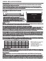
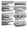
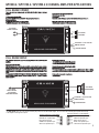
AMPLIFIERS
DRIVE
GPV800.2 / GPV1100.2 / GPV3500.2
GPV1200.4 / GPV1800.4 / GPV2400.4
GPV2100.1
Ground Pounder GPV AMPLIFIERS
Crunch is proud to introduce the finest high end car audio products available and would like to thank you for your
continued support. The Ground Pounder Series range of products have been designed to a very high level of
performance, with features unavailable in any other products. All of the amplifiers have variable crossovers built in,
with added touches such as subsonic filter, bass equalization and a bass remote control module for the mono
amps that allows bass control from with in reach of the drivers seat.
To insure years of listening pleasure, all amplifiers have a built in diagnostic mode that will detect shorted speaker
leads, low impedance, dangerous high temperatures, DC shorts and will shut down the amp to help prevent
serious damage.
INDEX
PAGE
General Installation Procedure.........................................................................................................................................................1
Amplifier Feature Descriptions..........................................................................................................................................................2
GPV800.2 / GPV1100.2 / GPV3500.2 2-CHANNEL AMPLIFIER APPLICATIONS.......................................................................3-4
Full range stereo / Full range mono
GPV1200.4 / GPV1800.4 / GPV2400.4 4 CHANNEL AMPLIFIER APPLICATIONS........................................................................5
4, 3 and 2 channel full range / 2 way active, with mono bass /
front/rear high pass using a 2 channel model for mono sub bass
GPV2100.1 A/B CLASS 1 CHANNEL AMPLIFIER APPLICATIONS................................................................................................6
Basic mono amplifier application
Features and Specifications..............................................................................................................................................................7
Setting Up Systems After Installation For Best Performance..............................................................................................................8
Troubleshooting and Diagnostics......................................................................................................................................................9
Product Warranty............................................................................................................................................................................10
Be sure to check out the Maxxsonics Extended Limited Warranty
Program on the bottom of the page
OEM Integration Accessories.....................................................................................................................................................11-12
Be sure to check us out at
www.youtube.com/maxxsonicsusainc
for product reviews and tutorials for
getting the most out of your audio system.
The contents of this manual may not be reproduced or copied with out the
written consent of MAXXSONICS USA, Inc.
GENERAL INSTALLATION PROCEDURE
System Design
The success of any car stereo system relies on several factors, such as the system design, execution of the installation, and system setup. Please
remember that any system is only as good as its weakest link.
Please remember that higher power systems are not necessarily useful purely for high sound pressure levels, but also to establish a headroom capability, to
reproduce musical peaks cleanly without distortion. Lower power amplifiers will clip earlier than their more powerful cousins, and cause loudspeaker failure when
overdriven, due to the harmonics generated by a clipped signal, thus overheating voice coils.
Amplifiers should be mounted with the fins running horizontally for best convection cooling, to minimize overheating. Purchase the best quality RCA cables you can
afford, for reliability and less engine noise interference in the audio system.
Installation
WOOD
It is highly recommended that the amplifier be mounted to a board of MDF or other solid
structure using the 4 mounting screws provided. Avoid mounting the
amplifier to metal as this can introduce noise and other unwanted issues. When mounting
the amplifier, ensure that it is mounted HORIZONTALLY, as shown in the diagram above, for
optimal heat dissipation. Mounting amplifiers to speaker enclosures is not recommended as
this can cause damage to the amplifier components. When choosing a location for
mounting the amplifier, ensure that you check for clearance from wires, gas tank, electrical
devices and brake lines etc.
DRIVE
GPV4500
GROUND POUNDER
4000 WATTS
General:
Run the wiring so that RCA cables are at least 18“ away from power and speaker cables. Keep RCA cables away from electrical devices in the vehicle that can cause
electrical noise, such as electric fuel pumps, emission control modules and other on-board electronic modules.
Power and ground connections(see the features matrix on page 9 for proper gauge cables per amplifier):
Use a sufficient gauge power cable and ground cable using the chart below as reference to what size wire you require. In a multi amplifier system, add the total value
of the manufacture recommended fusing to get your total system amperage. Some applications may require multiple runs of power wire to meet the system
requirements. In multi amplifier systems it is advisable to mount a large enough fuse right at the battery, and run one or multiple +12 volt power cables to a fused
distribution block near the amplifiers. It is then a simple matter to connect the +12 volt terminal of each amplifier to the distribution block. During this process, please
ensure that the main power fuse is removed to avoid shorting the electrical system. The main fuse must be within 12” of the vehicles battery.
Ground each amplifier with as short a ground lead as possible directly to the vehicle chassis using 4 gauge wire or equivalent to the size of the amplifiers’ power wire.
Use a ground distribution block, if you wish, but it is extremely important to keep the main ground lead from this distribution block to the chassis as short as possible ,
not more than 12“. The ground connection integrity to the chassis is very important, and the best way to achieve a good, solid electrical and mechanical contact is to
use a large round crimp lug, crimped and soldered to the ground cable. The next step is to scrape the paint off the vehicle chassis , slightly larger than the ground
lug, at the connection point. Drill a clearance hole in the chassis, the same size as the lug hole, and use a bolt, spring washer and nut to securely fasten the ground
lug. Use petroleum jelly to coat the bolt/lug connection, to prevent oxidization with time.
TIP: Use the same approach when installing head units, equalizers or any audio equipment for that matter - run short individual grounds from each piece directly to
the vehicle chassis, to minimize ground loops and system noise. All power, ground and speaker connections should be crimped and soldered for reliability. Make sure
that none of the cable insulation can chafe against exposed metal in the vehicle, causing short circuits to the chassis.
WIRE LENGTH
SYSTEM
AMPERAGE
10-13 ft.
13-16 ft.
16-19 ft.
19-22 ft.
22-28 ft.
8
6
4
4
4
4
50-65
6
4
4
4
4
2
68-85
4
4
2
2
2
0
85-105
4
2
2
2
2
0
105-125
4
2
0
0
0
0
125-150
2
0
0
0
0
0
35-50
WIRE GAUGE
7-10 ft.
NOTE: This Matrix is a general rule
of thumb. Please refer to the
manufacturers specific
requirements. GPV specifications
can be found on page 9.
Safe connection sequence:
After all cables are run, connect speaker wires to the speakers and amplifiers, then run and plug in RCA cables. Next, connect all power, ground, and remote turn on
leads. Now connect all +12 volt cables to the amplifier/s and distribution blocks and fuse holders. Finally, connect the main +12 volt cable to the battery, with the main
fuse removed, and we are almost ready to power up the system.
Power up the system:
The following procedure may seem like overkill, but there is nothing more frustrating when turning on a system for the first time, and it does not work properly
immediately.
First, make sure the head unit is off, and turn all level controls to minimum (counterclockwise), including the head unit volume control. Set all equalizers to 0 dB (no
boost), and all crossover frequency controls at approximate frequencies, as recommended by the loudspeaker manufacturer. Set all input selector and crossover
switches as required for the application. Remove all amplifier fuses, and insert the main fuse at the battery. If the fuse does not blow, you can insert the fuse in one of
the amplifiers, and we are ready to turn on the system. Turn the head unit on, insert a CD, or select a radio station, and increase the head unit volume control. If the
system sounds fine, turn off the head unit, and install fuses in the remaining amplifiers, one by one, till the complete system is powered up and functioning properly.
1
AMPLIFIER FEATURE DESCRIPTIONS
GROUND POUNDER GPV AMPLIFIERS:
Each model is capable of 4 & 2-Ohms stereo per channel, or 4-Ohms mono bridged operation except
the mono amps which are capable of 4, 2 and 1-Ohm loads.
The input sensitivities for rated output powers are variable from 0.2 volts to 5 volts on multi channel
models and 0.2 volts to 6 volts on mono models.
All crossovers are fully variable in their respective ranges.
Crossover filters are 12dB/Octave.
A POWER LED indicates the powered up and turned on condition
The X-OVER slide switch selects the internal crossover functions:
-The input signal is routed directly to the LINE OUT RCA jacks, regardless of the X-OVER setting
simplifying daisy chaining of amplifiers.
-HPF: Selects the built in HIGH PASS filter, variable from 60 Hz to 1.2kHz.
-FULL: Bypasses all crossovers for full frequency range operation.
-LPF: Selects the built in LOW PASS , variable from 30 Hz to 250Hz.
MODE: The mode switch allows you to choose Stereo for full range 2 channel operation or MONO
for bridging operation
HIGH INPUT: If your radio/CD player does not have unbalanced (RCA) outputs, you can use the
HIGH level (wire) inputs.
LINE INPUT: The line input accepts unbalanced (RCA) inputs from 0.2V to 5V.
LINE OUTPUT: The line output passes through signal from the line inputs which allows you to daisy
chain multiple amplifiers from one signal.
All Crunch amplifiers feature a comprehensive diagnostic system, with speaker lead short circuit, and
amplifier DC faults indicated by the red “PROTECT” LED.
CAUTION: DO NOT OPERATE ANY AMPLIFIER BELOW THE INTENDED IMPEDANCE. YOU
WILL CAUSE DAMAGE TO THE AMPLIFIER THAT WILL NOT BE COVERED UNDER THE
WARRANTY PRINTED IN THE BACK OF THE MANUAL. 2 & 4 Channel amps are capable of 4
and 2-Ohms wired stereo and 4-Ohms wired mono bridged. The mono amps are capable of 4, 2
and 1-Ohm.
GPV800.2 / GPV1100.2 / GPV3500.2 2-CHANNEL AMPLIFIERS
LINE OUT LINE INPUT
LEVEL
L + - gnd - +
HI INPUT
R
L
R
BASS EQ
HPF
X-OVER
LPF
MODE
FLASH
NO FLASH
5V 0.2V
0dB 9dB
60Hz 1.2KHz 30Hz 250Hz
FULL LPF HPF MONO
STEREO
Note that the LOW PASS signal is MONO.
-In the LPF position, the HIGH PASS filter acts as a subsonic
filter.
-When the LPF mode is selected, a 0 to +9dB, at 45Hz, BASS EQ is also switched in.
The 4 channel amps have the same features as the 2 channel models accept that there are 2 sets of
controls.
1 set for channels 1 & 2 and 1 set for channels 3 & 4.
In addition, the 4 channel models have a Mode switch which allows you to select 2, 3 or 4 channel
operation.
The X-OVER slide switch selects the internal crossover functions:
-The input signal is routed directly to the LINE OUT RCA jacks, regardless of the X-OVER setting
simplifying daisy chaining of amplifiers.
-HPF: Selects the built in HIGH PASS filter, variable from 60 Hz to 1.2kHz.
-FULL: Bypasses all crossovers for full frequency range operation.
-LPF: Selects the built in LOW PASS , variable from 30 Hz to 250Hz.
MODE: The mode switch allows you to choose Stereo for full range 2 channel operation or MONO
for bridging operation
HIGH INPUT: If your radio/CD player does not have unbalanced (RCA) outputs, you can use the
HIGH level (wire) inputs.
LINE INPUT: The line input accepts unbalanced (RCA) inputs from 0.2V to 5V.
LINE OUTPUT: The line output passes through signal from the line inputs which allows you to daisy
chain multiple amplifiers from one signal.
GPV1200.4 / GPV1800.4 / GPV2400.4 4-CHANNEL AMPLIFIERS
-The LINE INPUT signal is routed directly to the LINE OUT RCA jacks, regardless of the X-OVER
setting simplifying daisy chaining of amplifiers.
-SUBSONIC: Allows you to adjust the crossover filter from 15Hz to 55Hz.
-LPF: Allows yo to adjust the LOW PASS crossover filter from 40Hz to 150Hz.
LEVEL: Adjusts the input sensitivity from 0.2 volts to 6 volts.
BASS EQ: The Bass EQ is adjustable from 0db to 9dB.
REMOTE: This is the input jack for the remote Level control.
LINE INPUT: The line input accepts unbalanced (RCA) inputs from 0.2V to 6V.
LINE OUTPUT: The line output passes through signal from the line inputs which allows you to daisy
chain multiple amplifiers from one signal.
GPV2100.1 1-CHANNEL A/B CLASS MONO BLOCK AMPLIFIERS
CHANNEL 3 / 4
LINE INPUT
R
CH3
CH4
+ - gnd - +
HI INPUT
+ - gnd - +
L
CH3/4
CH1/2
CH1
CH2
LEVEL BASS EQ HPF
5V 0.2V
LEVEL BASS EQ HPF
5V 0.2V
LPF
0dB 9dB 60Hz 1.2KHz 30Hz 250Hz
X-OVER
MODE
FULL LPF HPF
2 3 4
CHANNEL
LPF
0dB 9dB 60Hz 1.2KHz 30Hz 250Hz
LINE OUT
FLASH
NO FLASH
X-OVER
FULL LPF HPF
CHANNEL 1 / 2
Note that the LOW PASS signal is MONO.
-In the LPF position, the HIGH PASS filter acts as a subsonic
filter.
-When the LPF mode is selected, a 0 to +9dB, at 45Hz, BASS EQ is also switched in.
POWER
BASS BOOST SUBSONIC
LOWPASS
LEVEL
FLASH
NO FLASH
PROTECT REMOTE
CONTROL
0dB
9dB
15Hz
55Hz 40Hz
150Hz 6V
0.2V
LINE OUT LINE INPUT
L
L
R
R
The mono amps are capable of 4, 2 & 1-Ohm loads.
Operating the amp below 1-Ohm can cause damage to the
amp not covered in the warranty.
2
GPV800.2 / GPV1100.2 / GPV3500.2 2 CHANNEL AMPLIFIER APPLICATIONS
FULL RANGE STEREO
This is the most basic application for the GROUND POUNDER Series 2 channel
amplifiers.
1. Interconnect cable checklist:
Connect the LINE INPUTS to the Radio/CD with good quality RCA cables.
2. Crossover Switch:
The X-OVER switch must be in the FULL position.
The MODE switch must be in the STEREO position.
NOTE: Minimum final loudspeaker impedances:
4 &-2-Ohms stereo mode or 4-Ohms mono mode
BRIDGED
L + - gnd - +
HI INPUT
5V 0.2V
LEVEL
0dB 12dB
BASS EQ
SPEAKER OUTPUT
- LEFT +
- LEFT +
R
FULL RANGE
SPEAKERS
DRIVE
HPF
60Hz 1.2KHz 30Hz 250Hz
FUSE
L
LINE OUT LINE INPUT
R
LPF
TO BATTERY + 12 volts VIA FUSE
X-OVER
FULL LPF HPF MONO
POWER INPUT
GND REM +12V
FULL RANGE
STEREO LINE INPUT
3. Crossover frequency control checklist:
N/A for full range operation.
4. Line Level:
Refer to the section “Setting up systems after installation for best performance”.
REMOTE TURN-ON
MODE
STEREO
CHASSIS GROUND
GROUND POUNDER
FULL RANGE MONO
Interconnect cable checklist:
A MONO signal source is required, such as would be available from the mono sub bass
output of an active crossover, whether stand alone, or built into a head unit or equalizer.
Important: Do not be tempted to connect the hot, or positive outputs, from any source
together to obtain a mono signal, as this could very well damage the output stage of that
source.
It is necessary to feed the SAME signal to both left and right inputs via a Y-adapter RCA
cable. Connect the mono speaker positive terminal to the LEFT +, and its negative
terminal to RIGHT -.
Crossover frequency control setting checklist:
N/A for full range operation.
TIP: If you are using the mono sub bass output of an active crossover, there is nothing
wrong with switching in the low pass filter in these amplifiers for a steeper low pass roll-off.
Minimum final loudspeaker impedance:
- 4-Ohms mono.
5V 0.2V
LEVEL
0dB 12dB
BASS EQ
SPEAKER OUTPUT
- LEFT +
- LEFT +
L + - gnd - +
HI INPUT
HPF
LPF
60Hz 1.2KHz 30Hz 250Hz
FUSE
R
FULL RANGE
MONO SPEAKER
DRIVE
TO BATTERY + 12 volts VIA FUSE
X-OVER
STEREO
MODE
FULL LPF HPF MONO
POWER INPUT
GND REM +12V
L
LINE OUT LINE INPUT
R
FULL RANGE
MONO LINE INPUT
VIA Y-ADAPTER
FROM MONO SOURCE
Switch setting checklist:
- The X-OVER switch must be in the FULL position.
- The MODE switch must be in the MONO position.
BRIDGED
This application illustrates the basic mono bridging method for all Crunch 2 channel
amplifiers.
GROUND POUNDER
REMOTE TURN-ON
CHASSIS GROUND
The HIGH LEVEL inputs are used when the radio/CD player does not have RCA cable outputs. You can connect the radio/CD player speaker wires directly
to the amplifier via the high Level Inputs.
Use both connectors for 4 CH amplifiers
Use this connector for 2 CH amplifiers
GRAY: CH 1 Speaker Input +
ORANGE: CH 3 Speaker Input +
BROWN: CH 1 Speaker input PINK: CH 3 Speaker input Black: Chassis Ground
Black: Chassis Ground
GREEN: CH 2 Speaker Input BLUE: CH 4 Speaker Input White: CH 2 Speaker Input +
YELLOW: CH 4 Speaker Input +
3
GPV800.2 / GPV1100.2 / GPV3500.2 2-CHANNEL AMPLIFIER APPLICATIONS
Stereo high pass with mono low-pass in a 2 way active, or bi-amplified system
In this application we will use a 2 channel amplifier for the high frequencies, and a second
one for the low frequencies, or mono sub bass. Please consult the speaker specifications
to determine maximum amplifier power requirements.
Crossover frequency control checklist:
Highs amplifier:
- HI PASS: 100 Hz
- LOW PASS: N/A
Interconnect cable checklist:
Connect the inputs of the HIGHS amplifier to a Radio/CD with good quality RCA cables.
Connect the LINE OUT of the HIGHS amplifier to the inputs of the BASS amplifier with a
stereo RCA to RCA cable.
Lows amplifier:
- HI PASS (Subsonic filter): 10 Hz to 40 Hz
- LOW PASS: 80 Hz
Mono bass woofer wiring:
Connect the mono speaker positive terminal to the RIGHT +, and its negative terminal to
LEFT -.
Please note that these frequency points are suggestions only. Refer to the loudspeaker
manufacturer specifications and the section “Setting up systems after installation for best
performance”
Switch setting checklist:
- Highs amplifier: X-OVER switch in the HPF position.
MODE switch in the STEREO position.
- Lows amplifier: X-OVER switch in the LPF position.
MODE switch in the MONO position.
Level control checklist:
- Refer to the section “Setting up systems after installation for best performance”
5V 0.2V
LEVEL
0dB 12dB
BASS EQ
BRIDGED
SPEAKER OUTPUT
- LEFT +
- LEFT +
FULL RANGE
SPEAKERS
DRIVE
HPF
60Hz 1.2KHz 30Hz 250Hz
FUSE
L + - gnd - +
HI INPUT
LPF
TO BATTERY + 12 volts VIA FUSE
X-OVER
FULL LPF HPF MONO
POWER INPUT
GND REM +12V
R
LINE OUT LINE INPUT
L
R
FULL RANGE
STEREO LINE INPUT
Minimum final loudspeaker impedances:
- 2-Ohms per channel stereo.
- 4-Ohms mono bridged.
REMOTE TURN-ON
STEREO
MODE
CHASSIS GROUND
GROUND POUNDER
STEREO
INTERCONNECT
RCA CABLE
5V 0.2V
LEVEL
0dB 12dB
BASS EQ
SPEAKER OUTPUT
- LEFT +
- LEFT +
L + - gnd - +
HI INPUT
HPF
LPF
60Hz 1.2KHz 30Hz 250Hz
FUSE
R
DRIVE
X-OVER
STEREO
MODE
FULL LPF HPF MONO
POWER INPUT
GND REM +12V
L
LINE OUT LINE INPUT
R
4
BRIDGED
MONO BASS
SPEAKER
GROUND POUNDER
TO BATTERY + 12 volts VIA FUSE
REMOTE TURN-ON
CHASSIS GROUND
GPV1200.4 / GPV1800.4 / GPV2400.4 4 CHANNEL AMPLIFIER APPLICATIONS
4 CHANNEL FULL RANGE SYSTEM
Here we show how to use the 4 channel amplifiers as straight forward discrete 4 channel
full range units.
Crossover frequency control checklist:
Channels 1/2:
- HI PASS: N/A
- LOW PASS: N/A
Channels 3/4:
- HI PASS: N/A
- LOW PASS: N/A
Interconnect cable checklist:
- Connect the four inputs of the amplifier to a Radio/CD with quality RCA cables.
Switch setting checklist:
- 1/2CH X-OVER: FULL
- 3/4CH X-OVER: FULL
- MODE: 4 CHANNEL
Level control checklist:
- Refer to the section “Setting up systems after installation for best performance”
Minimum final loudspeaker impedances:
- 2-Ohms per channel.
CH3
BRIDGED
CH4
FUSE
CHANNEL 3 / 4
LPF
LPF
TO BATTERY + 12 Volts VIA FUSE
REMOTE TURN-ON
CHASSIS GROUND
X-OVER
X-OVER
MODE
2 3 4
CHANNEL
BRIDGED
CHANNEL 1 / 2
0dB 12dB 60Hz 1.2KHz 30Hz 250Hz FULL LPF HPF
0dB 12dB 60Hz 1.2KHz 30Hz 250Hz FULL LPF HPF
LEVEL BASS EQ HPF
5V 0.2V
5V 0.2V
LEVEL BASS EQ HPF
CH 1/2 SPEAKER OUTPUT
- RIGHT +
- LEFT +
CH2
HI INPUT
+ - gnd - +
+ - gnd - +
CH1
DRIVE
POWER INPUT
GND REM +12V
CH1/2
LINE INPUT
CH3/4
CH 3/4 SPEAKER OUTPUT
- RIGHT +
- LEFT +
R
L
FULL RANGE
STEREO LINE
INPUTS
FULL RANGE
SPEAKERS
LINE OUT
FULL RANGE
SPEAKERS
GROUND POUNDER
2 or 3 CHANNEL FULL RANGE SYSTEM
Here we show how to use the 4 channel amplifiers as full range 2 or 3 channel units by
taking advantage of the mono bridging capability of all Crunch amplifiers.
Crossover frequency control checklist:
Channels 1/2:
- HI PASS: N/A
- LOW PASS: N/A
The following example shows how to create a 3 channel system by mono bridging
channel pair 3 / 4. In order to create a 2 channel system, simply follow the example to
also mono bridge channel pair 1 / 2.
Channels 3/4:
- HI PASS: N/A
- LOW PASS: N/A
Interconnect cable checklist:
- Connect the inputs of channel pair 1/2 to a suitable stereo source, e.g. a head unit
with good quality RCA cables.
- A MONO signal source is required to bridge channel pair 3/4, such as would be
available from the mono sub bass output of an active crossover, whether standalone,
or built into a head unit or equalizer.
Important: Do not be tempted to connect the hot, or positive outputs, from any source
together to obtain a mono signal, as this could very well damage the output stage of
that source.
- It is necessary to feed the SAME signal to both left and right inputs via a Y-adapter
RCA cable.
- Connect the mono speaker positive terminal to the LEFT +, and its negative terminal
to RIGHT - as shown.
Switch setting checklist:
- 1/2CH X-OVER: FULL
- 3/4CH X-OVER: FULL
- MODE: 3 CHANNEL
Level control checklist:
- Refer to the section “Setting up systems after installation for best performance”
Minimum final loudspeaker impedances:
- 2-Ohms per channel in stereo mode.
- 4-Ohms mono bridged.
CH3
BRIDGED
MONO
OR SUB BASS
SPEAKER
X-OVER
X-OVER
MODE
2 3 4
CHANNEL
BRIDGED
LPF
LPF
TO BATTERY + 12 Volts VIA FUSE
REMOTE TURN-ON
CHASSIS GROUND
POWER INPUT
GND REM +12V
CHANNEL 3 / 4
CHANNEL 1 / 2
0dB 12dB 60Hz 1.2KHz 30Hz 250Hz FULL LPF HPF
0dB 12dB 60Hz 1.2KHz 30Hz 250Hz FULL LPF HPF
LEVEL BASS EQ HPF
5V 0.2V
5V 0.2V
LEVEL BASS EQ HPF
FUSE
CH4
CH2
HI INPUT
+ - gnd - +
+ - gnd - +
CH1
DRIVE
CH 1/2 SPEAKER OUTPUT
- RIGHT +
- LEFT +
CH1/2
LINE INPUT
CH3/4
CH 3/4 SPEAKER OUTPUT
- RIGHT +
- LEFT +
R
L
1 STEREO
1 MONO
FULL RANGE
LINE INPUTS
TIP: If you are using the mono sub bass output of an active crossover, there is nothing
wrong with switching in the low pass filter in these amplifiers for a steeper low pass
rolloff.
LINE OUT
FULL RANGE
SPEAKERS
GROUND POUNDER
5
GPV2100.1 A/B CLASS 1 CHANNEL AMPLIFIER APPLICATION
Basic application
These sub bass amplifiers can be used in any of the bi-amplification systems described in
this manual, replacing the 2 channel amplifiers as per the illustrations.
Interconnect cable checklist:
Connect the inputs to a suitable source, e.g. a head unit with good quality RCA cables.
Connect the LINE OUT to the inputs of the system highs amplifier.
Use at least #12 gauge speaker wiring. The amps have dual speaker terminals,
simplifying the hookup of multiple speakers
Minimum final loudspeaker impedance: 1-Ohm.
+
+
9dB
15Hz
DRIVE
L
R
POWER
REM
LINE OUT LINE INPUT
L
R
TO BATTERY + 12 Volts VIA FUSE
REMOTE TURN-ON
CHASSIS GROUND
+12V
0.2V
LEVEL
150Hz 6V
LOWPASS
55Hz 40Hz
FUSE
BASS
BASS BOOST SUBSONIC
0dB
SPEAKER
-
MONO
SUBWOOFER
GND
MAXX
GPR-1
Level control checklist:
Refer to the section “Setting up systems after installation for best performance”
POWER
PROTECT REMOTE
CONTROL
MIN
Crossover frequency control checklist:
LOW PASS: 40Hz to 150Hz
SUBSONIC:15 Hz to 55 Hz
BASS EQ: 0 to +9dB
GROUND POUNDER
DESIGNATED
MONO OUTPUT
FROM HEAD UNIT
FULL RANGE
STEREO LINE INPUT
Y-ADAPTOR
FUSE
+
+
SPEAKER
-
-
PARALLEL MONO
SUBWOOFERS
2-OHMS EACH MINIMUM
NOT USED
GND
POWER
REM
+12V
Note: You can use the Radio/CD designated mono line output or a full range stereo line output.
For full range stereo line output, you will need an optional “Y-Adaptor” as shown.
6
7
SETTING UP SYSTEMS AFTER INSTALLATION FOR BEST PERFORMANCE
GPV800.2 / GPV1100.2 / GPV3500.2 / GPV1200.4 / GPV1800.4 / GPV2400.4
General:
At this point you are ready to get more specific on the settings for your amplifier.
High Pass:
-When in Hi Pass operation, this setting acts as a low frequency cut off for your system reproduction. The point that you set it at cuts off any frequencies from reproduction beyond this
point. The 12 o’clock position is a great starting point. EXAMPLE: If you adjust the High Pass to 100Hz, the amplifier will not play frequencies below 100Hz but will play frequencies from
100Hz to the chosen Low Pass frequency.
-When in Low Pass/Bandpass operation, this setting acts as a low frequency cut off for your system reproduction aka Subsonic Filter. The point that you set it at cuts off any frequencies
from reproduction beyond this point. The 12 o’clock position is a great starting point. EXAMPLE: If you adjust the High Pass to 25Hz, the amplifier will not play frequencies below 25Hz
but will play frequencies from 25Hz to the chosen Low Pass frequency.
-When in Flat/Full operation, the High Pass crossover is bypassed.
Bass EQ:
This setting is a fixed bass boost at 45Hz that is variable from 0-9dB. This feature provides impact to your bass, but if not adjusted correctly, it can be over used and cause damage to
your speakers and amplifiers. It is best to slowly turn this setting clockwise until the desired punch is felt. It is not recommended to exceed the 12 o’clock position unless listening at a low
volume or a low recording quality as this can result in high distortion and possibly clipping.
Low Pass:
The Low Pass control acts as a ceiling and doesn’t allow frequencies to the right of the desired setting to be reproduced. Turning the potentiometer all the way to the right is a great
starting point. EXAMPLE: If you adjust the Low Pass to 120Hz, the amplifier will not play frequencies above 120Hz but will play frequencies from 120Hz to the chosen Hi Pass or
Subsonic frequency.
-When in Hi Pass operation, this setting is bypassed.
Level Control Setup:
Ensure that the Level is turned completely to the left prior to turning the system on. Next you should insert a CD or cassette that you are familiar with to use as a reference, and turn the
head unit volume control to about 80% of its full setting. The system sound level will of course be very low, and the following procedures will help you to match the amplifier input
sensitivities properly to the head unit output signal level.
It is important to match the amplifier LEVEL input sensitivity to the Radio/CD output sensitivity. This can be located in the Radio/CD manual.
If the Radio/CD output sensitivity is 2 volts, then adjust the amplifier LEVEL input to 2 volts.
If you are not sure what the Radio output sensitivity is, follow these general guide lines:
Turn the level control up slowly, till you hear distortion, then back off a few degrees on the control. If at any point your amplifier goes into protection, you will need to turn the Level to the
left a bit and then try again. If you reach a point where the output does not increase, stop turning the Level control to the right as the amplifier/speaker combo has reached its maxx
output in this application.
GPV2100.1
General:
At this point you are ready to get more specific on the settings for your amplifier.
Subsonic:
This setting acts as a low frequency cut off for your system bass reproduction. The point that you set it at cuts off any frequencies from reproduction beyond this point. The 12 o’clock
position is a great starting point. EXAMPLE: If you adjust the Subsonic to 25Hz, the amplifier will not play frequencies below 25Hz but will play frequencies from 25Hz to the chosen Low
Pass frequency.
Bass EQ:
This setting is a fixed bass boost at 45Hz that is variable from 0-9dB. This feature provides impact to your bass, but if not adjusted correctly, it can be over used and cause damage to
your subwoofers and amplifiers. It is best to slowly turn this setting clockwise until the desired punch is felt. It is not recommended to exceed the 12 o’clock position unless listening at a
low volume or a low recording quality as this can result in high distortion and possibly clipping.
Low Pass:
The Low Pass control acts as a ceiling and doesn’t allow frequencies to the right of the desired setting to be reproduced. The 12 o’clock position is a great starting point. EXAMPLE: If you
adjust the Low Pass to 80Hz, the amplifier will not play frequencies above 80Hz but will play frequencies from 80Hz to the chosen Subsonic frequency.
Level Control Setup:
Ensure that the Level is turned completely to the left prior to turning the system on. Next you should insert a CD or cassette that you are familiar with to use as a reference, and turn the
head unit volume control to about 80% of its full setting. The system sound level will of course be very low, and the following procedures will help you to match the amplifier input
sensitivities properly to the head unit output signal level.
It is important to match the amplifier LEVEL input sensitivity to the Radio/CD output sensitivity. This can be located in the Radio/CD manual.
If the Radio/CD output sensitivity is 2 volts, then adjust the amplifier LEVEL input to 2 volts.
If you are not sure what the Radio output sensitivity is, follow these general guide lines:
Turn the level control up slowly, till you hear distortion, then back off a few degrees on the control. If at any point your amplifier goes into protection, you will need to turn the Level to the
left a bit and then try again. If you reach a point where the output does not increase, stop turning the Level control to the right as the amplifier/subwoofer combo has reached its maxx
output in this application.
Sit back and enjoy the music!
8
TROUBLESHOOTING A SYSTEM
The key to finding the problem in a misbehaving sound system is to isolate parts of that system in a logical fashion to track down the fault.
Description of the PROTECT system built into all GROUND POUNDER amplifiers
The diagnostic system will shut down the amplifier, until reset by turning the head unit off, and back on. This state of affairs will be indicated by the front panel PROTECT
LED lighting up under the following conditions:
1 - A sort circuit on the loudspeaker leads.
2 - An internal amplifier fault that causes a DC offset on the loudspeaker output.
Should the amplifier go into protect mode, simply disconnect all RCA and speaker leads, while keeping +12 volt, power ground and remote leads connected.
1. Now turn the amplifier back on, and if the diagnostic LED lights, the amplifier has an internal fault.
2. If not, plug the RCA cables back, and reset the amplifier. If it goes into diagnostic now, the fault lies in the input, either with bad cables or source unit.
3. If the amplifier seems fine with RCA cables plugged in, connect the speakers, one at a time, and if one of the speakers or its wiring is faulty, it will activate the diagnostic
system.
Amplifier heatsink overheating
The amplifiers will shut down when the heatsink temperature reaches 80 degrees centigrade, and turn back on once the unit has cooled down below that point.
Causes of overheating:
1 - Inadequate cooling - relocate or remount to provide better natural airflow over the fins.
2 - Driving high power levels into low impedances - back off on the volume control, and/or make sure you are not loading the amplifier with less than the recommended
loudspeaker impedance.
Low output power
1 - Check that level controls have been set up properly.
2 - Make sure that the battery voltage, as measured at the amplifier’s +12 volt and ground terminals, is 11 volts or more.
3 - Check all +12 volt and ground connections.
Fuses blowing
1 - The use of loudspeaker impedances below the recommended minimums will draw more current - check.
2 - A short on the main +12 volt cable from the battery to the vehicle chassis will cause the main fuse to blow.
3 - If an amplifier fuse blows continually, with only +12 volt, ground and remote leads connected, the amplifier may be faulty.
System does not turn on
1 - Check all fuses.
2 - Check all connections.
3 - Measure the +12 volt and remote turn on voltages at the amplifier terminals. If these are non existent or low, take voltage measurements at fuse holders, distribution
blocks, the head unit’s +12 volt and remote leads to localize the problem.
Noise problems
System noise can be divided into two categories, hiss, and electrical interference.
Hiss, or white noise
1 - High levels of white noise usually occurs when amplifier level controls are turned up too high - readjust according to the procedures in section ”Setting up systems after
installation for best performance”
2 - Another major problem that can cause excessive hiss, is a noisy head unit - unplug the amplifier input RCA cables, and if the hiss level reduces, the source unit is at fault.
Electrical interference
The inside of an automobile is a very hostile electrical environment. The multitude of electrical systems, such as the ignition system, alternator, fuel pumps, air conditioners,
to mention just a few, create radiated electrical fields, as well as noise on the +12 volt supply and ground. Remember to isolate the problem - first unplug amplifier input RCA
cables, if the noise is still present, check the speaker leads, if not, plug the RCA’s back, and investigate the source driving the amplifier, one component at a time.
A ticking or whine that changes with engine RPM:
1 - This problem could be caused by radiation pickup of RCA cables too near to a fuel pump or a distributor, for instance, - relocate cables.
2 - Check that the head unit ground is connected straight to the vehicle chassis, and does not use factory wiring for ground.
3 - Try to supply the head unit with a clean +12 volt supply directly from the battery +, instead of using a supply from the in dash wiring/fusebox.
A constant whine:
This type of noise can be more difficult to pinpoint, but is usually caused by some kind of instability, causing oscillations in the system.
1 - Check all connections, especially for good grounds.
2 - Make sure that no speaker leads are shorting to exposed metal on the vehicle chassis.
3 -RCA cables are notorious for their problematic nature, so check that these are good, in particular the shield connections.
9
CRUNCH
Maxxsonics Limited Warranty
As the manufacturer of Maxxsonics, Autotek, Crunch, MB Quart and Hifonics car audio products,
Maxxsonics USA Inc. Warrants to the original consumer purchaser the amplifier to be free from
defects in material and workmanship for one (1) Year from date of purchase.
All other parts and accessories of the system are warrantied to be free from defects in
material and workmanship for one (1) year from date of purchase. Maxxsonics will
repair or replace at it’s option and free of charge during the warranty period, any system
component that proves defective in materials and workmanship under normal installation,
use and service provided that the product is returned to the authorized Maxxsonics dealer
from where it was purchased. A photo copy of the original receipt must accompany the
product being returned.
Valid purchase receipts will contain the name and address of the authorized reseller.
Any damage to the product as a result of misuse, abuse, accident, incorrect wiring,
improper installation, alteration of date code or bar code labels, revolution, natural
disaster, or any sneaky stuff because someone messed up, repair or alteration out side
of our factory or authorized service centers and any thing else you have done that you
should not have done is not covered.
This warranty is limited to defective parts and specifically excludes any incidental
or consequential damages connected therewith. This warranty is not to be construed
as an insurance policy.
Warranty on installation labor, removal, re-installation and freight charges are not the
responsibility of Maxxsonics USA Inc.
Warranty products damaged as a result of insufficient or improper packing materials
are not covered by this limited warranty and such damaged product will be returned
“as is” at the expense of the owner.
For information regarding Maxxsonics
Extended Limited Warranty Program,
please visit www.maxxwarranty.com
10
OEM Integration
Accessories
MX-1 Premium High To Low Level Converter
* Converts High Level OEM speaker wires to Ultra Clean RCA
Low Level Outputs
* High Level Inputs: Accepts all types of High level Inputs
including floating ground and high voltages up to 30 volts.
* Audio Signal Sense / Hardwire Turn-On: Audio sense detects
music signals from the OEM wires and activates the MX-1. As
an option, the module also offers a remote turn-on wire.
* Parametric Bass EQ: Features Bass Boost, adjustable Band
Width (wide & narrow), Low Pass and Subsonic Filter.
* Clipping Indicators: Visually indicates audio signals Pre-Clip,
Soft Clip and Hard Clip
* Balanced Line Output: Ultra clean DIN variable high voltage
output for driving mono amps.
* Remote Output: Driver circuit to turn on amplifier when
module activates.
* Bass Remote: Features for subwoofer Level control with builtin clipping indicators.
* Input & Output Level Control: Allows for gain matching both
radio and amplifier audio signals.
MX-3 Bass Controller
* Parametric Bass EQ: Provides a wide array of subwoofer output signal
shaping controls to enhance bass response and sound quality including
Bass Boost, adjustable Bandwidth (wide and narrow), Low Pass and
Subsonic Filter.
* Accepts a wide range of incoming music signal levels while
accommodating all types of head units and signal processors and
controlling the output level to the amp to maximize a signal strength up to
9 volts.
* Clipping Indicators: Visual clipping indicators provide indication of
damaging clipped signals to help protect the subwoofer(s) and amplifier.
Includes pre-clip, soft-clip and full-clip indications.
* Music Shaping: Shapes the music signal to achieve deep bass notes as
low as 15Hz.
* Bass Remote: Included bas Remote features built-in clipping indicators
allows direct bass control from in-dask or under-dash.
MX-2 Deluxe High To Low Level Converter
MX-4 Add A Sub High To Low Level Converter
* Converts High Level OEM speaker wires to Ultra Clean RCA
Low Level Outputs
* High Level Inputs: Accepts all types of High level Inputs
including floating ground and high voltages up to 30 volts.
* Audio Signal Sense / Hardwire Turn-On: Audio sense detects
music signals from the OEM wires and activates the MX-2. As
an option, the module also offers a remote turn-on wire.
* Remote Output: Driver circuit to turn on amplifier when module
activates.
* Converts High Level OEM speaker wires to Ultra Clean RCA Low Level
Outputs
* High Level Inputs: Accepts all types of High level Inputs including
floating ground and high voltages up to 30 volts.
* Audio Signal Sense / Hardwire Turn-On: Audio sense detects music
signals from the OEM wires and activates the MX-4. As an option, the
module also offers a remote turn-on wire.
* Remote Output: Driver circuit to turn on amplifier when module activates.
11
Accessories
5V
SLAVE
ON
3V
MASTER
35Hz
MODE
250Hz
LOW PASS
FILTER
24 dB/OCT
9V
0.2V
INPUT
LEVEL
7V
1V
RED - CLIP
GREEN - 9V
9V
OUTPUT
LEVEL
15Hz
MAXX-LINK
MLX-100
0
180
0dB
PHASE
+10 dB
BOOST
30Hz
BANDWIDTH
BYPASS
-20dB
NORMAL
0dB
LEVEL
RED - CLIP
GREEN - 9V
35Hz
SUBSONIC
FILTER
24 dB/OCT
100Hz
FREQUENCY
PARAMETRIC BASS EQ
-6dB
12
OFF
TEST TONE
65Hz
PART#: S611