1
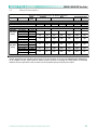
MA9.6K, MA9.6K DSP User Guide The Martin Experience All material © 2010. Martin Audio Ltd. Subject to change without notice. Contents Important safety instructions...................................................................... 3 Warning notices ........................................................................................... 4 1 Installation and operation...................................................................... 7 1.1 1.2 1.3 1.4 1.5 1.6 1.7 2 Setup and settings using the amplifier’s front panel controls ......... 12 2.1 2.2 2.3 2.3.1 2.3.2 2.3.3 2.3.4 2.3.6 2.3.7 2.3.8 2.3.10 2.3.11 2.3.12 2.3.13 2.3.14 2.3.15 2.3.16 2.3.17 2.3.18 2.3.19 3 Unpacking ................................................................................................. 7 Mounting ................................................................................................... 7 Operating Precautions ............................................................................. 8 AC Main connection ................................................................................. 8 Connecting Inputs .................................................................................... 9 Connecting Outputs ............................................................................... 10 Connecting Remote Control .................................................................. 11 Introduction............................................................................................. 12 The main screen ..................................................................................... 13 The main menu ....................................................................................... 13 Output attenuation ................................................................................. 14 Gain/Sensitivity....................................................................................... 15 Input select ............................................................................................. 15 Max output voltage ................................................................................. 15 Clip limiter CH1 - CH2 ............................................................................ 15 Gate CH1 - CH2 ....................................................................................... 16 KETH........................................................................................................ 16 Bar meters ............................................................................................... 16 Output meters ......................................................................................... 17 Temperature ............................................................................................ 17 Mains meters........................................................................................... 17 Hardware info.......................................................................................... 17 Hardware monitor ................................................................................... 18 The Smartcard function ......................................................................... 18 LCD contrast ........................................................................................... 19 Set unlock code ...................................................................................... 19 Service ..................................................................................................... 19 DSP ....................................................................................................... 20 3.2 3.3 3.4 3.6 3.7 3.8 3.9 3.10 3.10.1 Single value numeric parameters input................................................ 20 Handling local presets ........................................................................... 21 Handling Smartcard presets .................................................................. 21 Menu locking........................................................................................... 23 Amplifier name........................................................................................ 23 DSP signal path ...................................................................................... 23 DSP features ........................................................................................... 24 DSP Submenu ......................................................................................... 24 Restore flat .............................................................................................. 25 All material © 2010 Martin Audio Ltd. Subject to change without notice 1 3.10.2 3.10.2.1 3.10.2.2 3.10.2.3 3.10.2.3.1 3.10.2.3.2 3.10.2.4 3.10.3 3.10.3.1 3.10.3.2 3.10.3.3 3.10.3.4 3.10.3.5 3.10.3.6 3.10.3.7 3.10.3.9 3.10.3.9.1 3.10.3.9.2 3.10.4 3.11 3.12 3.2 4.1 4.2 4.3 4.4 4.5 5 Common settings ................................................................................... 25 Source selection ..................................................................................... 25 Main delay ............................................................................................... 25 AES3 ........................................................................................................ 25 Gain trim .................................................................................................. 25 If no link ................................................................................................... 25 Sound velocity ........................................................................................ 26 CH1, CH2, CH1+2 Settings ..................................................................... 26 EQ ............................................................................................................ 26 Q/Bandwidth, Q/Gain and shelving slope dual mode input ................ 26 Low-pass and high-pass filters ............................................................. 27 Polarity .................................................................................................... 27 Channel delay ......................................................................................... 27 Gain ......................................................................................................... 28 Peak Limiter ............................................................................................ 28 Advanced ................................................................................................ 29 Damping Control .................................................................................... 29 Filters Definition ..................................................................................... 30 Channel Settings Copy .......................................................................... 30 How to Setup a crossover ..................................................................... 30 Setup a bridged configuration............................................................... 32 MA Control Manager Overview.............................................................. 32 Turn-On/Turn-Off muting ....................................................................... 35 Short circuit protection .......................................................................... 35 Thermal protection ................................................................................. 35 DC fault protection ................................................................................. 35 Input/Output protection ......................................................................... 35 Maintenance ......................................................................................... 36 5.1 5.2 5.3 Cleaning .................................................................................................. 36 Service ..................................................................................................... 36 Dust removal ........................................................................................... 36 6 Warranty ............................................................................................... 37 7 Technical notes .................................................................................... 38 7.1 7.2 7.3 7.4 Block diagram ......................................................................................... 38 Thermal Dissipation ............................................................................... 39 Specification ........................................................................................... 40 Technical Drawing .................................................................................. 41 All material © 2010 Martin Audio Ltd. Subject to change without notice 2 Important safety instructions Caution To reduce the risk of electric shock, do not remove the cover. No user-serviceable parts inside. Refer servicing to qualified service personnel. Safeguards Electrical energy can perform many useful functions. This unit has been engineered and manufactured to assure your personal safety. Improper use can result in potential electrical shock or fire hazards. In order not to defeat the safeguards, observe the following instructions for its installation, use and servicing. Approvals * This equipment has been tested and found to comply by Competent Body (Directive 89/336/EECEMC) pursuant to the product family standard for audio professional use: EN 55103-1 and EN 55103-2 standard); EN61000- 3 - 2, EN 61000 - 3 - 3. In a domestic environment this product may cause radio interferences in which case the user may be required to take adequate measures. NOTES: This equipment has been tested and found to comply by Competent Body (Directive 89/336/EEC-EMC) pursuant to the product family standard for audio professional use: EN 55103-1 and EN 55103-2 standard ); EN61000- 3 - 2 , EN 61000 - 3 - 3. This is a class A product. In a domestic environment this product may cause radio interferences in which case the user may be required to take adequate measures. This equipment has been tested and found to comply by Notified Body (Directive 2006/95/EEC L.V) pursuant to the audio apparatus safety requirements: Standard EN 60065. All material © 2010 Martin Audio Ltd. Subject to change without notice 3 Warning notices Location Install the amplifier in a well-ventilated location where it will not be exposed to high temperature or humidity. Do not install the amplifier in a location that is exposed to direct rays of the sun, or near to hot appliances or radiators. Excessive heat can adversely affect the cabinet and internal components. Installation of the amplifier in a damp or dusty environment may result in malfunction or accident. Precautions regarding installation Placing and using the amplifier for long periods on heat-generation sources will affect performances. Avoid placing the amplifier on heat-generating sources. Install this amplifier as far as possible from tuners and TV sets. An amplifier installed in close proximity to such equipment may cause noise or degradation of the picture. WARNING: To prevent fire or electric shock: Do not expose this equipment to rain or moisture. Apparatus shall not be exposed to dripping or splashing and no objects filled with liquids, such as vases, shall be placed on the apparatus”. Safety rules This device must be powered exclusively by earth connected mains sockets in electrical networks compliant to the IEC 364 or similar rules. It is absolutely necessary to verify this fundamental requirement of safety and, in case of doubt, requires an accurate check by qualified personnel. The constructor cannot be considered responsible for eventual damages caused to persons, things or data for the missing of accurate earth link. Before powering this device verify that the amplifier is supplied with the correct voltage rating. Verify that your mains connection is capable to satisfy the power ratings of the device. Do not spill water or other liquids into or on the unit. Do not use this unit if the electrical power cord is frayed or broken. Do not remove the cover. Removing the cover will expose you to potentially dangerous voltage. No naked flame sources such like lighted candles should be placed on the amplifier. Contact the authorized centre for ordinary and extraordinary maintenance. Speaker damage Martin Audio 9.6K & 9.6K DSP amplifiers are among the most powerful professional amplifiers available and are capable of producing much more power than many loudspeakers can handle. It is the user's responsibility to use suitable speakers with the amplifier and to use them in a sensible way that will not cause damage. Martin Audio will not be responsible for damaged speakers. Consult the speaker manufacturer for powerhandling recommendations. Even if you reduce the gain using the amplifier's front panel attenuation controls, it is still possible to reach full output power if the input signal level is high enough. A single high-power crescendo can damage highfrequency drivers almost instantaneously, while low-frequency drivers can usually withstand very high, continuous power levels for a few seconds before they fail. Reduce power immediately if you hear any All material © 2010 Martin Audio Ltd. Subject to change without notice 4 speaker "bottoming out" - harsh pops or cracking distortion that indicate that the speaker voice coil or diaphragm is striking the magnet assembly. Martin Audio recommends that you use amplifiers of this power range for more headroom (cleaner sound) rather than for increased volume. Speaker output shock hazard A Martin Audio amplifier is capable of producing hazardous output voltages. To avoid electrical shock, do not touch any exposed speaker wiring while the amplifier is operating. This manual contains important information on operating your Martin Audio amplifier correctly and safety. Please read it carefully before operating your amplifier. If you have any questions, contact your Martin Audio dealer. All material © 2010 Martin Audio Ltd. Subject to change without notice 5 Introduction The totally new Martin Audio MA9.6K, & 9.6K DSP technology has changed the way the world looks at professional audio amplification. No other amplifiers come close for applications demanding high power and long term reliability. Thanks to amazing reductions in heat output along with reductions in weight and the specific high output power, MA9.6K & 9.6K DSP amplifiers can be used in an unlimited range of applications such as concert touring, opera houses, theatres, churches, cinema, theme parks, television sound stages and stadiums. More sound and less weight Compared to a conventional amplifier, Martin Audio MA9.6K & 9.6K DSP technology offers very high efficiency and delivers more power to the loudspeakers with greatly reduced heat dissipation. This greater efficiency enables dimensions, weight and power consumption to be reduced. The output stages of the amplifiers typically run at 95% efficiency, dissipating only 5% of the input energy as heat. One of the most interesting characteristics is that MA9.6K & 9.6K DSP efficiency is almost independent of output level. Conventional amplifiers achieve their best efficiency only at full rated power output. Since standard music has an average power density of 40% of the maximum level, conventional amplifiers can easily generate 10 times more heat than MA9.6K, & 9.6K DSP amplifiers for the same volume of sound. Superior Sound-Sonic Accuracy Crystal-clear highs and a tight, well-defined low end: the most accurate reproduction of an audio signal. Patented design features ensure very high performance over parameters such as distortion, frequency response, slew rate, power bandwidth and dumping factor. Totally Digital with High Reliability The MA9.6K & 9.6K DSP series is based on PWM technology that has been used for 30 years or more in power supplies and inverters. PWM provides high reliability, small size, low weight and high efficiency. A PWM converter works as a high frequency sampler, converting the variable amplitude (audio) signal into an impulse sequence with average value equal to the audio input. MA9.6K & 9.6K DSP amplifiers use very high sampling frequencies to obtain high performances across the audio band. The Best Amplifier for Your Mains Martin Audio MA9.6K & 9.6K DSP amplifiers adopt Power Factor Correction. This unique feature ensures that a predominantly resistive load is presented to mains, minimizing current distortion and voltage/current displacement. This leads to much improved performance of the amplifier at high levels of output and avoids mains-voltage collapses, typical of standard and switching power supplies. Another great advantage of this technology is that its performance is, to a large extent, independent of mains voltage. The rated output power does not vary with load/line conditions. Martin Audio MA9.6K & 9.6K DSP power amplifiers Martin Audio MA9.6K & 9.6K DSP power amplifiers have many advanced features, Digital control of many parameters, adjustable maximum mains consumption, selectable digital presets and a graphic display that shows detailed information of the status of the amplifier. You can appreciate the functionality of these and a lot of other features by reading this manual carefully. The Show Always Goes On The MA9.6K & 9.6K DSP Series is completely protected against every possible error in operation and are designed to work under every condition. They will deliver maximum power with maximum safety and increased long-term reliability. Anticipating potential problems at the design stage means your show always goes on! All material © 2010 Martin Audio Ltd. Subject to change without notice 6 1 1.1 Installation and operation Unpacking Carefully open the shipping carton and check for any noticeable damage. Every Martin Audio amplifier is completely tested and inspected before leaving the factory and should arrive in perfect condition. If you find any damage, notify the shipping company immediately. Be sure to save the carton and all packing materials for the carrier's inspection. 1.2 Mounting The 9.6K & 9.6K DSP amplifiers will mount in a standard 19" rack. Four front panel mounting holes are provided. Rear support mounting holes are also provided. These should always we used to support the weight of the amplifier at the rear in a 19” rack. Your MA9.6K, & 9.6K DSP amplifiers uses a forced-air cooling system to maintain a low, even operating temperature. Drawn by an internal fan, air enters through the slots in the front panel and courses over and through components. The MA9.6K & 9.6K DSP series amplifiers feature an "intelligent" variable-speed DC fan which is controlled by heat sink temperature sensing circuits: the fan speed will increase only when the temperature of either heat sink requires it, which keeps fan noise to a minimum and helps cut dust accumulation inside. Under extreme thermal load, the fan will force a very large volume of air through the heat sinks. All material © 2010 Martin Audio Ltd. Subject to change without notice 7 If either heat sink gets too hot, its sensing circuit will reduce the output power. If the amplifier overheats, another sensing circuit shuts down its circuit to cut off power until it cools to a safe temperature. The exhaust cooling air is forced out through the rear of the chassis (see below), so make sure there is enough space around the sides of the amplifier to allow the air to escape. If it is rack mounted, make sure the exhaust air can flow without resistance. If you are using a rack with closed backs, there must be at least one standard rack space of opening in the front of the rack for every four amplifiers. Amplifiers may be stacked directly on top of each other (no space needed between units), starting from the bottom of the rack. 1.3 Operating Precautions Make sure the AC mains voltage is correct and is the same as that printed on the rear of the amplifier. Damage caused by connecting the amplifier to improper AC voltage is not covered by the warranty. Make sure the power switch is off before making any input or output connections. It is always a good idea to have the gain controls muted during power-up to prevent speaker damage particularly if there is a high signal level at the inputs. Whether you purchase them or build them yourself, use good quality input and speaker cables. Most intermittent problems are caused by faulty cables. Use good quality connectors and cable along with good soldering technique to ensure trouble free reliability. 1.4 AC Main connection The AC Main connection is made via the CPC type connector on the rear side of the panel. The figure below shows the connection to the amplifier. Be sure that your AC mains power source has the requirements indicated in this manual. MA9.6K & 9.6K DSP amplifiers have an automatic power factor correction system for a perfect mains network interface. The amplifier is a resistive load for the mains network, minimizing the reactive power and the harmonic distortion on the current. The system allows performance to be maintained even in circumstances of varying the mains voltage. Is important to connect the ground for safety, do not use adapters that disable the ground connection. All material © 2010 Martin Audio Ltd. Subject to change without notice 8 1.5 Connecting Inputs Input connections are made via the 3-pin XLR-female type or 1/4" phone Jack connectors on the rear side of the amplifier. The figure below shows the connection of analog input for balanced and unbalanced line. You can use either configuration, but you must consider that unbalanced long lines can introduce noise in the audio system. The Link switch located in the rear panel is for direct paralleling the rear input connectors. You can use the remaining input connector to carry signal to other amps. All material © 2010 Martin Audio Ltd. Subject to change without notice 9 1.6 Connecting Outputs Warning: there are lethal voltages at the loudspeaker connectors when the amplifier is turned on. To prevent any damages turn the amplifier off before connecting the loudspeaker. Output connectors are made via Neutrik Speakon connectors. Consult the wire gauge chart to find a suitable wire gauge to minimize power and damping factor losses in the speaker cables. The outputs can also work in bridge mode. For each device the 1+ and 2+ pins of Speakon connector are paralleled internally and have to be considered as the positive output of the channel; likewise the 1- and 2- pins of Speakon connector are also paralleled internally and should be treated as the negative output of the channel. Note: Channel B is run out of phase internally, corrected by reversing the connections from the amplifier output to the output connecter Channel A is run in phase. By having channel A and B operating in opposite polarity, the energy storage in the power supply is more efficient. This is significant for signals below 100Hz (sub bass etc.) and improves the power bandwidth. Be sure to use balanced inputs on all measurement equipment (including oscilloscope probes) if you are bench testing. All material © 2010 Martin Audio Ltd. Subject to change without notice 10 1.7 Connecting Remote Control You can control the amplifier via the RS485 interface; the illustration shows the wiring configuration for the connection of the data cable to the RJ45 socket located on the rear panel of the amplifier. The same picture shows also the ID selection for Remote Control (in this case ID= 28); to change the ID; rotate the selectors at the desired position. All material © 2010 Martin Audio Ltd. Subject to change without notice 11 2 2.1 Setup and settings using the amplifier’s front panel controls Introduction The figure right shows the front panel of 9.6K, & 9.6K DSP Amplifiers. The front panel controls, in conjunction with the graphic LCD display above the buttons, give the user the total control and detailed information about the status of the amplifier. Each pushbutton has multiple functions and the display shows the current active function for each button. Read the instructions below carefully which will explain the many functions of the amplifier. All material © 2010 Martin Audio Ltd. Subject to change without notice 12 2.2 The main screen The illustration below shows the main screen; this screen appears after a short presentation when the user powers on the amplifier. In the first line, after power on, "WAIT" appears; if the system parameters are normal, the display is replaced with "READY". During the normal operation the controller monitors the system parameters. If a parameter is out of range, the correspondent error code is shown on the LCD meter of the relevant channel on the third line; if the abnormal parameter is associated with both channels, the error code is written in the centre. The LED bars can function as output voltage or output current meters; in the first case the LCD meters function as output current meters, vice versa in the second case. The first green LED at the bottom of the LED bar when illuminated indicates the presence of input audio signal above -60 dBV on the corresponding channel. From the second green LED to the yellow one, each LED will illuminate for every 3 dB increase in level. The green LEDs will be illuminated during normal operation. The yellow LED will light at -2 dBu. If the level of the audio signal reaches the channel maximum output capability, the red LED will be triggered. The LED bars also have diagnostic function; a flashing yellow LED indicates a critical range of temperature (from 80°C to 85°C) of the power devices on the corresponding channel, if this LED is lighting constantly, the temperature is above 85°C. A constantly lit red LED indicates that the corresponding channel is in protection. The fourth line of the screen shows the functions of the buttons below; The "lock" function is activated if the corresponding button is pressed or more than 1 second; in this case all the other buttons are locked. The same operation unlocks these buttons (unlock code is required - see section 2.3.18 for more details). The "mute" buttons switch off the two channels independently; in this case "muted" appears on the first line. The same operation disables the mute function. If the "menu" button is pressed, the main menu is displayed on the LCD screen. 2.3 The main menu The illustration shows the main menu. You can scroll the menu items by pushing the up or down buttons and choose the selected function by pressing "ok" (if the chosen item enables or disables a function, display showing "on" is replaced with "off" for disabling it, or "on" for enabling it. See below for menu tree. Main menu All material © 2010 Martin Audio Ltd. Subject to change without notice 13 The Amplifier menu diagram 2.3.1 Output attenuation The illustration below shows the Output attenuation screen. You can choose to set CH1, CH2 or both by pushing the "C1+2" button. The "+" and "-" buttons change the value of the output attenuation in the range from 0 to -30dB. Note: for the best sonic performance it is recommended that you set the attenuation to 0db (no attenuation), and select the proper gain/sensitivity from the following menu. All material © 2010 Martin Audio Ltd. Subject to change without notice 14 2.3.2 Gain/Sensitivity The illustration below shows the Gain/Sensitivity screen. You can choose to set CH1, CH2 or both by pushing "C1+2" button. The "+" and "-" buttons change the value of the gain. The values of gains permitted are 26, 29, 32 and 35 dB. Martin Audio strongly recommends the use of the default 32dB setting as this is the industry standard and is the basis for the limiter thresholds used in all Martin Audio loudspeaker controllers and published speaker parameters. 2.3.3 Input select You can choose between two different input modes (if available): Analog and Ethernet. The up and down buttons change the selection; the "sel" button locks the selected option. 2.3.4 Max output voltage The illustration below shows the Max output voltage screen. You can choose to set CH1, CH2 or both by pushing "C1+2" button. The "+" and "-" buttons change the value of the max output peak voltage. 2.3.5 Max mains current The Max mains current screen is shown below. The "+" and "-" buttons change the value of the max mains current draw in the range from 15 to 32A. - 2.3.6 Clip limiter CH1 - CH2 Enable this function to prevent distortion due to excessive amplitude of the output signal leading to a “clipped” waveform. You can enable/disable it by pushing the on/off button. CAUTION: There is the risk of damage to the loudspeakers if the Clip Limiters are deactivated. You should not deactivate Clip Limiters unless their function is taken over by external devices, such as All material © 2010 Martin Audio Ltd. Subject to change without notice 15 digital system controllers. In such cases it is mandatory, to correctly set the parameters in the external device. 2.3.7 Gate CH1 - CH2 This function allows muting of the amplifier channels individually if the input signal amplitude is falling below the values shown in the following table. You can enable/disable the gate by pushing the on/off button. Gating the output is delayed by 5 seconds after input signal removal, and follows in reversed way the bottom green LED on the CH1, CH2 bar LED display *(muted if green LED is off). 2.3.8 KETH This section is not currently implemented. 2.3.10 Bar meters In the Bar meters screen you can select the LED bargraphs to operate as output voltage meters and the LCD bargraphs in the main screen as output current meter (by selecting "LED Volt, LCD Curr), or vice versa (by selecting the other option). All material © 2010 Martin Audio Ltd. Subject to change without notice 16 2.3.11 Output meters In the Output meters screen you can view the values of the output signal for CH1 and CH2. Furthermore, the impedance of the load is shown on the bottom line of the screen (see illustration). Minimum output voltage for impedance measurements is 10Vrms; measurements values are stored in a logbook. Time between single impedance measurements can be up to several minutes depending on program signal. Output power is shown as maximum value every 200 ms. C1+C2 shows the output values are being shown in bridge mode. 2.3.12 Temperature In the Temperature screen you can view the historic temperature diagram of the last four hours of the final current use in the range from 10 to 90°C; in the bottom-right side of the screen the present value is shown. 2.3.13 Mains meters In the Mains meters screen you can view the voltage and the current of the connected mains supply. 2.3.14 Hardware info In this screen you can view information regarding the amplifier hardware: S/N the serial number of the amplifier HW ID the hardware identifier If you push the "more" button, you can view additional info; KFRNT the version number of the front panel KCTRL the version number of the controller KETH the version number Ethernet adapter Lifetime the operating time of the amplifier All material © 2010 Martin Audio Ltd. Subject to change without notice 17 2.3.15 Hardware monitor In this screen you can view details regarding the system parameters: PWRBSCH1 - PWRBSCH2 amplifier power supply voltages channel 1-2 VAUX internal auxiliary voltages If you press the "more" button you can view the remaining parameters: +5VAN auxiliary analog voltage VEXT external remote control voltage VAUX if "OK" is displayed, auxiliary voltages of the power supply are correct. IGBTCONV if "OK" is displayed, the DC/DC converter monitor function properly 192KHZ if "OK" is displayed, the frequency system clock is correct 2.3.16 The Smartcard function The Smartcard operates as memory and can be used to save the settings of the amplifier. These settings can be loaded into other amplifiers saving considerable time compared to manually entering identical settings. When you insert the smartcard in the slot over the LCD screen, the screen shown below appears. You can select the desired option by pushing up or down button and "ok" to activate it. The option "Recall local preset" does not appear if the smartcard is blank. All material © 2010 Martin Audio Ltd. Subject to change without notice 18 2.3.17 LCD contrast In this screen you can set the contrast of the LCD display by pushing the +/- buttons. 2.3.18 Set unlock code In this screen you can insert the numeric key to unlock the settings. The same screen appears when the “unlock” button in the main screen is pressed. There is a universal key to unlock the settings. This is 270156. 2.3.19 Service This function is factory reserved. All material © 2010 Martin Audio Ltd. Subject to change without notice 19 3 3.1 DSP Menu changes The addition of a KDSP board converts a standard MA9.6K to a 9.6K DSP. This can be done at the time of ordering or retrospectively at a later date. New firmware in installed which causes some reorganization of the K-Series menu. The main differences are the division of the Settings menu into two (or more) submenus, one for the amplifier-related settings, one for the KDSP settings and the other for additional add-on board, and the introduction of a local presets menu from which the user will be able to store and recall to/from local memory all settings entered both on the amplifier and KDSP. The amplifier settings menu is almost the same as the “Settings” menu of the non-DSP version. The only differences are the introduction of an input selection command and the new idle mode function. The input selection can be used to switch from analog input to digital AES3 input, with or without DSP processing. The idle mode function is a power saving feature. When activated, the output stage switches off if the amplifier doesn’t detect an input signal for the user defined amount of time. This saves about 40 W of power per channel. This means reduced heat, longer amplifier and fan life, and lower electricity bills for permanently powered, fixed installation systems. A menu locking feature in the Setup menu and an amplifier name feature in the Display menu have been added. The DSP settings submenu is the menu from which all the DSP processing parameters can be entered. See the following pages for details. 3.2 Single value numeric parameters input The numeric input mode has been extended with a fine/coarse feature to cater for the large number of parameters now available. When you edit a parameter, you start in the “fine” mode. The steps applied by the – and + keys are the minimum allowable for that parameter. You can switch to the “coarse” mode by clicking the “fast” key. The “fast” key will be renamed “slow”. All material © 2010 Martin Audio Ltd. Subject to change without notice 20 Coarse steps are equivalent to 10 fine steps so editing will be 10 times faster. Steps are automatically repeated by keeping the – or + key pressed. 3.3 Handling local presets Up to 50 presets may be stored on the amplifier’s local memory. The current amplifier settings and KDSP board settings are stored on the local memory by using the local preset Save command. The menu will ask you to choose one of the 50 available presets, showing the preset number and name. Available preset positions will be shown “empty”. You can enter the preset name by pressing ok. The selected character is arrowed, and is modified by pressing – or + keys. The next character is selected by pressing sel key. Finish the procedure by pressing the ok key to store the preset. Preset selection Preset name input You can load and apply a stored preset by using the Recall local preset. This uses an identical dialog. Please note that all the current amplifier settings are overwritten! 3.4 Handling Smartcard presets It is the possible to store up to 150 presets for each settings smartcard. The menu is activated when the smartcard is inserted in the amplifier if the main page of the menu is selected. The store and recall procedures are identical to those used for local presets. All material © 2010 Martin Audio Ltd. Subject to change without notice 21 3.5 Handling preset names Note that the current preset name, either entered by you or loaded from the local memory or from a smartcard, is retained by the amplifier and used as starting point for a new preset saving operation. The menu will ask if you want to keep/edit that name or if you would like to edit the name of the preset that is going to be overwritten. This is useful for copying presets to or from a smartcard. For instance, if you load a preset named “18IN SUB 1” from a smartcard, and then save it into local memory: Select Keep name? Modify current name Use existing name All material © 2010 Martin Audio Ltd. Subject to change without notice 22 3.6 Menu locking In addition to the basic push-button locking function, a new menu locking strategy has been introduced for the DSP version of the amplifier. There are three levels of locking: All locked Information may be displayed but not altered. Presets cannot be loaded Allow safe User can change from Analog input to AES3 input with DSP into the signal path. Some common DSP parameters can be changed (AES gain trim, main delay, DSP input selection). Only local presets can be recalled, and they should all be safe for the speaker system connected to that amplifier (example: HF driver –3 dB, HF driver 0 dB, HF driver +3 dB). Allow all All settings menus are enabled. User can recall presets from either local memory or smartcard. Local presets can be made Read-Only by enabling the “Lock presets” function, in order to preserve the original settings stored on the amplifier. The lock code, when set different from 000000, protects the whole Menu locking submenu. 3.7 Amplifier name The amplifier name, together with the current preset name, can be displayed by enabling the “Display amplifier data” function. The 20-character amplifier name and the 40-character preset name are shown differently when the amplifier is in the starting page of the main menu. The amplifier name can be assigned via the “Edit amplifier name” command (see Handling local presets above). 3.8 DSP signal path The KDSP board embeds a very advanced digital signal processor. There are some features found only in high level sound processors, and some new utilities that can only be implemented in a completely integrated DSP/amplifier system. A complete block diagram of the processing chain is shown below All material © 2010 Martin Audio Ltd. Subject to change without notice 23 3.9 DSP features AES3 digital input high performance (128 dB SNR) analogue input high performance (122 dB SNR) analogue output latest generation SHARC DSP with 40 bit floating point signal path for noiseless processing enhanced IIR filtering routine optimized for the highest SNR up to 2 seconds of main delay PEQ16: fully parametric equalizer, 16 band, each with 8 different filter shapes (peaking, hi/lo shelving, hi/lo pass EQ, band pass, band stop, all pass) alignment delay with high temporal resolution crossover with IIR Butterworth, Bessel and Linkwitz-Riley filters advanced crossover with FIR linear phase brick-wall filters speaker and amplifier monitor and analyzer to estimate power and load impedance peak limiter with look-ahead true power limiter to avoid burning voice coils while getting the maximum performances from drivers patented damping control and cable resistance compensation: get optimally damped bass response regardless of cable length 3.10 DSP Submenu All material © 2010 Martin Audio Ltd. Subject to change without notice 24 3.10.1 Restore flat This command resets to default values all the DSP parameters after a confirmation request. Flat frequency response, 0 dB gain, + polarity, no delay, no limiters and no damping control. Input signal parameters, such as the stereo/parallel input mode and the AES3 gain trim are NOT modified. 3.10.2 Common settings These parameters are applied (identical) to both channels. 3.10.2.1 Source selection This menu allows you to choose the input selection mode. In “Stereo Mode” the signal on CH1 IN is processed and then goes to CH1 OUT, and that on CH2 IN is processed and then goes to CH2 OUT. In “Parallel from CH1” the signal on CH1 IN goes on both CH1 and CH2 out, through independent DSP processing. Similarly, in “Parallel from CH2” mode the source is the signal on CH2 IN. 3.10.2.2 Main delay This is the delay that is applied to both channels. This is mainly intended for delayed speaker systems. The delay ranges from 0 to 2000 ms, in 1 ms increments. 3.10.2.3 AES3 This menu controls the AES3 input options. 3.10.2.3.1 Gain trim This menu sets the gain to be applied at the signal coming from the AES3 digital input. Setting 0 dB makes a full-scale digital signal equivalent to an analog input signal of 20 dBu. 3.10.2.3.2 If no link This menu controls the behaviour if the AES3 signal connection fails or becomes unreliable (>1% of errors). You can choose either “mute” or “analogue”. If “mute” is selected, when the AES3 connection fails, the amplifier will mute the output. If “analog” is selected, when the AES3 connection fails, the amplifier will take the signal from the analog input. The switching is done in real time to avoid a glitch. If the input levels are correctly matched between analog input and AES3 input (use AES3 GAIN TRIM parameter), the switching between AES3 and analog will be inaudible. When you use the analog input backup, you must run the amplifier in parallel mode to select only one digital input channel and you have to connect the corresponding analog signal cable in the ANALOG IN1 plug. The amplifier must be patched like this: All material © 2010 Martin Audio Ltd. Subject to change without notice 25 Analogue backup mode connection: the amplifier runs with AES3 input selected, in parallel mode. In the above example diagram, the R channel of the AES3 stream is selected, which is the “Parallel from CH2” choice from Source Selection submenu. Also the L channel can be used, by selecting “Parallel from CH1”. This signal goes, through processing, to both amplifier outputs. A cable with an analogue signal identical to that provided by AES3 should be connected to IN1 of the amplifier for backup purposes. The level should be accurately trimmed, by using the AES3 gain trim setting, or by changing the analogue signal level. 3.10.2.4 Sound velocity This option sets the sound velocity used for time to distance conversions throughout the local interface. It can be set from 320 m/s to 360 m/s. 3.10.3 CH1, CH2, CH1+2 Settings The channel (or the channels) that are being edited are shown on the top-right corner in these sub-menus: CH1, CH2, or 1+2 when you are editing both channels at once. 3.10.3.1 EQ This menu lists the 16 parametric filters. You can move from filter to filter using the arrow keys. The parameters are synthesised on the display. You can check all equaliser settings by switching through all 16 filters. You can change the settings for the selected filter by clicking “edit”. You can enable the filter or set it to a flat response. You can choose the filter type from the following types: peaking (Peak) low (LSh) and high (HSh) shelving (from 3 to 15 dB/oct) low pass EQ (LPEQ) and high pass EQ (HPEQ) bandstop (Notch) bandpass (BandP) allpass (AllP) You can change: The frequency in 1/96 octave steps from 20Hz to 20 kHz. the gain – for peaking or shelving filters – in 0.1dB from –15 to +15 dB the Q factor - for all filters except shelving – in 0.1 steps from 0.1 to 30 the shelving slope from 3 to 15 dB/oct 3.10.3.2 Q/Bandwidth, Q/Gain and shelving slope dual mode input All material © 2010 Martin Audio Ltd. Subject to change without notice 26 Peaking/Bandpass/Bandstop/Allpass Lowpass/Highpass EQ Shelving 3.10.3.3 Low-pass and high-pass filters This menu sets up the crossover filters. There are 2 available filters, one low-pass (LP) filter and one highpass (HP) filter. By using both, you will obtain a band-pass response. Both traditional IIR and brick-wall linear phase FIR filters are implemented. The classic IIR crossover filters can be selected as a Butterworth, Bessel or Linkwitz-Riley shape. In the first two cases, the Freq. parameter defines the –3 dB point, in the latter, the –6 dB point. The slope is freely selectable from 6dB/octave (1st order filter) to 48dB/octave (8th order filter). The FIR filters can be selected as normal (FIR) or enhanced (FIR+). The enhanced version gives a higher out-of-band rejection, at the expense of a little (<10 degrees) phase nonlinearity. In both cases, the minimum working frequency is related to the desired latency. A 400Hz minimum working frequency gives a latency of 2ms. It is better, therefore, to use the FIR filters for upper midranges or mid-high crossovers for which the phase coherency is a key point. The use of the FIR filters causes the deactivation of the limiter look-ahead feature, in order to preserve the overall 2.0 ms latency. 3.10.3.4 Polarity This menu allows the user to reverse the signal polarity. 3.10.3.5 Channel delay This menu allows two different transducers to be time aligned. The selectable delay varies from 0 to 30 ms in 10.4us steps. All material © 2010 Martin Audio Ltd. Subject to change without notice 27 3.10.3.6 Gain This menu changes the channel gain, from –40 dB to +15 dB, in 0.1dB steps. 3.10.3.7 Peak Limiter This menu controls the output peak limiter voltage threshold, attack time and decay time. When editing the threshold, the display shows in real-time the gain reduction due to the limiting function (GR = …dB), together with the limiting voltage referred to the input. The limiter has a look-ahead buffer, in order to soften the clipping and to minimise distortion. The default value of the look-ahead time is 1.5 ms. When FIR filters are activated; the limiter look-ahead feature is deactivated to preserve the overall 2.0 ms latency. Peak Limiter All material © 2010 Martin Audio Ltd. Subject to change without notice 28 3.10.3.8 Power limiter This menu controls the output power limiter which decreases the gain in order to reduce the power delivered to the load. The amplifier measures the load current to estimate the actual active power output being delivered. Given the low efficiency of electromechanical transducers (<10%), almost the same level of power is transformed into heat in the driver voice coil. This limiter is intended to avoid burning the voice coils of the drivers while exploiting their maximum performances. The parameters are the power threshold in W at which the gain begins to get reduced, the attack time, that is the response time of the limiter intervention and the decay time, that is the time constant after which the gain is restored to the nominal gain. You should select as power threshold the true power handling of your speaker (it is usually between one third and one half of the declared RMS or AES power handling, see the table below), with time constants related to the thermal inertia of your speaker (the mass to be heated). So, huge 4” VC subwoofers could require some seconds of attack and some seconds of release time, while tiny 1’ VC tweeters may need less than 1/10 of second of attack time. When editing the threshold, the display shows in real-time the gain reduction due to the combined peak/power limiting function (GR = xx.x dB) and the power really delivered to the load (Pavg=xxxxW). Power Limiter DRIVER 1” VC tweeter 1.5” VC tweeter 2” VC horn driver 3” VC horn driver 4” VC horn driver 2” VC midrange 3” VC midbass 4” VC woofer 4” VC subwoofer 6” VC massive subwoofer POWER THRESHOLD 10…20 W 20…30 W 20…40 W 30…50 W 40…60 W 30…100 W 50…150 W 100…200 W 150…300 W 250…500 W ATTACK TIME 100 ms 150 ms 200 ms 300 ms 500 ms 500 ms 1000 ms 2000 ms 4000 ms 6000 ms DECAY TIME 300 ms 300 ms 400 ms 500 ms 3000 ms 3000 ms 5000 ms 5000 ms 8000 ms 10000 ms Suggested power limiter settings for common used drivers. The power limiter should be used to protect the drivers from burning, and at working levels it normally shouldn’t activate. Check the gain reduction, it should not raise over 2-4 dB even during loud passages of music, in order to obtain the optimal sound. Note that a normal musical signal has very loud peaks, but a low average level, while a continuous tone has a much higher average power even if it has a modest impact on the ear. 3.10.3.9 Advanced These are advanced settings that are not usually found on any other sound processor or amplifier;- 3.10.3.9.1 Damping Control This unique and patented feature allows you to add a “virtual” resistor in series with the amplifier output. The value of this resistor can also be negative in order to get the correct damping factor with any cabling you use. For example, if you use a 10 meters cable for powering the subs, you will add a parasitic series resistance (0.3 ohm for example). By enabling the damping control, you can add a negative resistance that compensates the cable resistance. All material © 2010 Martin Audio Ltd. Subject to change without notice 29 WARNING: when enabled, a lowpass filter cutting around 400 Hz is automatically inserted into the chain. This feature is intended to be used only for subwoofer applications. AWG 16 16 16 14 14 14 12 12 12 Sq mm 2 x 1.5 mm2 2 x 1.5 mm2 2 x 1.5 mm2 2 x 2.5 mm2 2 x 2.5 mm2 2 x 2.5 mm2 2 x 4 mm2 2 x 4 mm2 2 x 4mm2 Length 5m 10 m 20 m 5m 10 m 20 m 5m 10 m 20 m Resistance 0.13 Ohm 0.26 Ohm 0.52 Ohm 0.08 Ohm 0.16 Ohm 0.32 Ohm 0.05 Ohm 0.10 Ohm 0.20 Ohm Typical cabling resistance. Another advantage is that you can take in account the voice coil rise in resistance due to heating, getting a correctly damped bass response in the average working condition. For example, if you run your subwoofer amplifiers hard during your performance, you should add a negative resistance between 1 and 2 Ohms to keep the correctly damped response. This value is correct for an 8 Ohm typical subwoofer; remember to divide it for the number of paralleled speakers on the K amplifier output. Take into account that if you use the system at a lower level, you should select a smaller negative resistance to avoid an over damped response. This setting will be linkable to the actual average level automatised in the next firmware release… Average power / rated power 10% 20% 50% 100% Power compression 1.4 dB 2.0 dB 2.8 dB 4.5 dB Equivalent series resistance for 8 Ohm driver 1.0 Ohm 1.4 Ohm 2.1 Ohm 3.8 Ohm Typical rise in resistance due to voice coil heating. Note the huge amount (3.8 Ohm) when the driver reaches its thermal limit. 3.10.3.9.2 Filters Definition This feature allows to emulate the parameters input of some commercial audio processors, in order to get the same equalizer frequency response by simply inputting the same parameter values. You should not learn some complicated conversion formulas or frequency response definitions to get the same behaviour of the processor you are used to work with. In the current version, the supported modes are Powersoft (Type1) and alternative (Type2), contact Powersoft support for correlation with other Processing Units from other manufacturers. 3.10.4 Channel Settings Copy By selecting the “CH1+2, copy CH1=>CH2” submenu, all the CH2 DSP settings are cloned from the CH1, and then the parameters of both channels are changed at the same time. The same applies for “CH1+2, copy CH2=>CH1”. 3.11 How to Setup a crossover For example, midrange on CH1 and high frequency driver on CH2. Edit CH1, go to LP Filter, set Active=ON All material © 2010 Martin Audio Ltd. Subject to change without notice 30 Set Frequency = 2000 Hz Set Shape=Linkwitz-Riley (You could also experiment with shape=FIR) Set Slope=24dB/oct. Edit CH2 Go to HP Filter, set Active=ON Set Frequency = 2000 Hz All material © 2010 Martin Audio Ltd. Subject to change without notice 31 Set Shape=Linkwitz-Riley (or FIR) Set Slope=24dB/oct On CH2, edit Ch Delay to temporal align midrange with highs horn. On CH2, edit Gain to align levels. 3.12 Setup a bridged configuration If you already have a preset made for a non-bridged configuration, lets say for the CH2 for example, you should load the preset, then choose to edit “CH1+2, copy CH2=>CH1”. The CH1 now is identical to CH2. With this command you can also edit both channels at the same time. Otherwise, you can immediately choose “CH1+2, copy CH1=>CH2” or “CH1+2, copy CH2=>CH1”, then edit both channels at once. Remember that, in bridged mode, the 2 DSP channels should be identical to get the right results. 3.2 MA Control Manager Overview Both the standard and DSP versions of the MA9.6K may be remote controlled from a PC using the MA Control Manager software which may be downloaded from the Martin Audio website;http://www.mauserguides.com.red-square.net/Ampsoft/ContMan.pdf The application may be used to control many amplifiers, particularly in an installation environment and offers a host of extremely useful programming and monitoring facilities. Amplifiers are connected to a PC using an RS485 convertor and with each assigned a unique address, connections can either be daisy-chained between amplifiers or connected in star configuration from an RS485 hub which gives the additional facility of remote power switching All material © 2010 Martin Audio Ltd. Subject to change without notice 32 MA Control Manager main screen The main screen shows all amplifiers that are part of the network and gives an instant at-a-glance overview of the entire system. Amplifier Settings Window Each amplifier can be opened and all parameters adjusted on line in real time making a complex system very straightforward to set up compared to spending hours going through each front panel menu. This is particularly true of the DSP versions of the MA-K series amplifiers where the additional functions can be easily accessed All material © 2010 Martin Audio Ltd. Subject to change without notice 33 The EQ Window from an MA5.2K DSP Control Manager also offers a phenomenal array of test, analysis and monitoring tools to manage any installation with unparalleled ease. A scheduler is available to switch amplifiers on or off at a specified time either daily or weekly. A record of amplifier performance including temperature can be accessed and tests run on individual amplifiers or the entire system. The software can even be configured to e-mail or send an SMS message in the event of a specified fault condition such as an impedance or temperature error. All material © 2010 Martin Audio Ltd. Subject to change without notice 34 4 4.1 Protection Turn-On/Turn-Off muting For about four seconds after turn-on, and immediately at turn-off, the amplifier outputs are muted. 4.2 Short circuit protection A short circuit protection system safeguards the amplifier's output transistors under short circuits and other stressful loads. It is completely inaudible when inactive. In case of short circuit, the red LED will be light-up and writing "PROT" appears in the first line of the display (see Par. 2.2 for a detailed description). The amplifier will reset itself 50 times every 2 seconds. Once 50 resets have been performed, if the fault still exists on the output, the unit goes into permanent protection mode. A power OFF/ON cycle is needed to restart the unit. 4.3 Thermal protection The MA9.6K and 9.6K DSP amplifiers use a continuously variable speed fan to assist cooling (the fan speed changes in response to the amplifier's cooling needs). If the heat sink temperature reaches approximately 80°C, the yellow LED starts to flashing. If the temperature is more then 85°C the thermal sensing circuitry will mute each power section channels, the LED will light permanently and the power supply will be cut off. Once the heatsink has cooled down, the amplifier will automatically reset and the LED will go out. The temperature can be reduced by reducing the output power. 4.4 DC fault protection If DC or excessive subsonic energy appears at a channel output, an instantaneous protection circuit will cut off the power supply for both channels. Power supply shutdown is used instead of speaker relays, thereby improving the damping factor and reliability of the MA9.6K & MA9.6K DSP amplifiers. 4.5 Input/Output protection An ultrasonic network decouples RF from the outputs and keeps the amplifier stable with reactive loads. All material © 2010 Martin Audio Ltd. Subject to change without notice 35 5 5.1 Maintenance Cleaning Disconnect the amplifier from the AC main source first; use a soft cloth and mild non-abrasive solution to clean the faceplate and chassis. 5.2 Service There are no user-serviceable parts in your 9.6K or 9.6K DSP amplifier. Refer servicing to qualified technical personnel. If your 9.6K or 9.6K DSP amplifier needs repair, contact your Martin Audio dealer or distributor. 5.3 Dust removal Particularly in dusty environments, the front side filters clog with dust and dirt after prolonged use, this will interfere with cooling. You may use compressed air to remove the dust from filters. To remove air filters unscrew the retaining screws and rotate the covering grill; repeat the same operation on the other side. All material © 2010 Martin Audio Ltd. Subject to change without notice 36 6 Warranty Martin Audio MA9.6K and MA9.6K DSP Amplifiers are warranted against manufacturing defects in materials or craftsmanship over a period of 4 (four) years from the date of original purchase. During the warranty period Martin Audio will, at its discretion, either repair or replace products which prove to be defective provided that the product is returned in its original packaging, shipping prepaid, to an authorised Martin Audio service agent or distributor. Martin Audio Ltd. cannot be held responsible for defects caused by unauthorised modifications, improper use, negligence, exposure to inclement weather conditions, act of God or accident, or any use of this product that is not in accordance with the instructions provided by Martin Audio. Martin Audio is not liable for consequential damages. This warranty is exclusive and no other warranty is expressed or implied. This warranty does not affect your statutory rights. All material © 2010 Martin Audio Ltd. Subject to change without notice 37 7 7.1 Technical notes Block diagram The illustrations below show the output stage block diagram and the power supply block diagram. All material © 2010 Martin Audio Ltd. Subject to change without notice 38 7.2 Thermal Dissipation Martin Audio MA9.6K & MA9.6KDSP Level Load Rated Power Switch off or remote power off by software* Power on, amplifier in idle mode Pink Noise (1/8 rated power) Pink Noise (1/4 rated power) 8Ω / Stereo 16Ω / bridged 4Ω / stereo 8Ω / bridged 2Ω / stereo 4Ω / bridged Watt 2 x 1500 1 x 3000 2 x 3000 1 x 6000 2 x 4800 1 x 9600 8Ω / Stereo 16Ω / bridged 4Ω / stereo 8Ω / bridged 2Ω / stereo 4Ω / bridged 2 x 1500 1 x 3000 2 x 3000 1 x 6000 2 x 4800 1 x 9600 AC Mains 230V AC 115V AC 0.86 0.8 0.52 1.6 Out Watt In Dissipated 0 0 2.95 160 2.95 160 Ampere Watt Thermal Dissipation BTU/hr Kcal/hr 10 546 2.5 138 BTU/hr Kcal/hr 2.7 5.5 375 469 254 771 195 4.8 9.5 750 938 348 1069 270 7.2 14.4 1200 1500 460 1444 365 4.7 9.3 750 938 348 997 252 8.7 17.4 1500 1875 535 1593 402 13.6 27.1 2400 3000 760 2342 591 *Power absorbsion with amplifier switched off is not zero because to comply with EN60065/IEC 60065:200112 all amplifier circuitry must include a “bleed” resistor across the incoming AC mains power to discharge residual current to prevent the risk of shock from an amplifier disconnected from the mains. All material © 2010 Martin Audio Ltd. Subject to change without notice 39 7.3 Specification POWER REQUIREMENTS Power supply................................................................................................115-230V (-15%, +15%) (50/60Hz) Power factor.........................................................................................more than 0.95 from 500W to full power Operating temperature .................................................................................................................... 0° C, 45° C Weight........................................................................................................................................ 12Kg (26.5 lbs) External dimensions Width……………………………………………………………………..……..…..Standard 19” Rack: 483mm (19”) Depth…………..………………………………………….………………………………………………475mm (18.7”) Height…………………………………………………….…………………………………1 Rack Unit: 44mm (1.75”) AUDIO SECTIONS Bandwidth (1W, 8Ohm)......................................................................................................20Hz, 20KHz ±0,2dB Damping factor (8Ohm)................................................................................................... (20Hz, 200Hz) > 5000 Slew Rate (8Ohm)................................................................................................50V/uS (input filter bypassed) S/N ratio.......................................................................................................................................................>109 Distortion THD……………………………………….…..... Max < 0.5% from 1W to full power (typically < 0.05%) Intermodulation SMPTE …………………………....……. Max < 0.5% from 1W to full power (typically < 0.05%) Intermodulation DIM 30.................................................... Max<0.5% from 1W to full power (typically < 0.05%) Inputs............................................................................................Balanced to ground, XLR female combo jack Impedance..............................................................................................10KOhm each leg balanced to ground Gain ……………………………………..…………….….…………………...…....26, 29, 32, 35dB, user selectable Outputs….……...…...High current Neutrik 4-pole Speakon connectors (pins 1+ 2+ paralleled, 1-2- paralleled) Data……………………………………………………………………………………………..………RS485 via RJ45 OUTPUT SPECIFICATIONS Output Power EIAJat 1KHz, 1% THD 8Ω Per Channel………….……………………………………………………………………………………….1500W 4Ω Per Channel………….……………………………………………………………………………………….3000W 2Ω Per Channel…………………………………………………………………………………………………..4800W 16Ω Bridged……………………………………………………………………………………………………….3000W 8Ω Bridged…………………………………………………………………………………………………...……6000W 4Ω Bridged……………………………………………………………………………………………………...…9600W Max output voltage……………………………………………………………………………………………….…169V Max output current………………………………………………………………………………………………...…85A FEATURES Display…………………………………………………………………………………. LCD matrix interactive display Indicators…………………………………………………………..……2 x Multi-function 7 segment LED bargraph Data Storage and Transfer…………...........................................................…………………Smart Card Reader All material © 2010 Martin Audio Ltd. Subject to change without notice 40 7.4 Technical Drawing All material © 2010 Martin Audio Ltd. Subject to change without notice 41