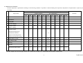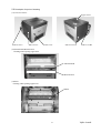
1
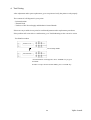
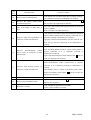
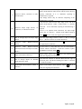
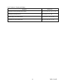
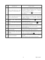
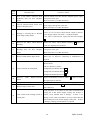
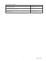
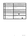
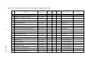
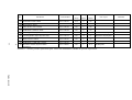
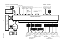
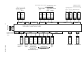
Digital Photo Printer
CHC-S1245-5
Maintenance Specifications
Date:
Revised:
Revision:
March 8, 2005
First Edition
Confirmation Signature
(Customer: )
(Shinko Electric Co., Ltd.)
Approved
Inspected
Drew
Shinko Electric Co., Ltd.
YQE8-J0092E
Revision Record
Revised Date
Correction
Descriptions
ECN No.
symbol
3/8/2005
-
First Edition
YQE8-J0092E
Contents
1.Scope ....................................................................................................................................................1
2.Periodic Inspection................................................................................................................................2
2.1 Parts Required.................................................................................................................................................. 2
2.2 Tools Required ................................................................................................................................................ 2
2.3 Tool Required .................................................................................................................................................. 2
2.4 Maintenance Schedule ..................................................................................................................................... 3
2.5 Inspection Contents ......................................................................................................................................... 4
2.6 Description for point of cleaning ..................................................................................................................... 6
2.7 Description for point of lubrication ............................................................................................................... 11
3.Adjustment ..........................................................................................................................................14
3.1 Power Unit Voltage Setting ........................................................................................................................... 14
3.1.1 +5V Setting............................................................................................................................................. 14
3.1.2 Thermal Head Power (THV) Setting ...................................................................................................... 15
3.1.3 +24V Verification................................................................................................................................... 15
3.2 Timing Belts Adjustment............................................................................................................................... 16
3.2.1 For Feed Roller Drive ............................................................................................................................. 16
3.2.2 For Feed Roller Drive ............................................................................................................................. 16
3.2.3 For Roll Paper Drive............................................................................................................................... 16
3.3 Print Density Adjustment .............................................................................................................................. 17
3.4 Resetting Maintenance Print Counter and Cutter Counter............................................................................. 18
4.Test Printing ........................................................................................................................................20
5.Troubleshooting ..................................................................................................................................21
5.1 How to Use This Specification ...................................................................................................................... 21
5.2 Troubleshooting Table................................................................................................................................... 22
5.2.1 Troubles during Power On and Off ........................................................................................................ 22
5.2.2 Error Messages on LCD Display when Power Is On ............................................................................. 24
5.2.3 Troubles in Operation Buttons and Indicators ........................................................................................ 29
5.2.4 Troubles in Paper Feed ........................................................................................................................... 31
5.2.5 Troubles in Feeding Ink Ribbon ............................................................................................................. 34
5.2.6 Troubles in Printing and Contents of Printing ........................................................................................ 36
5.2.7 Occurrence of Abnormal Noise .............................................................................................................. 39
5.2.8 Troubles in Connection........................................................................................................................... 41
Appendix 1: Maintenance Parts List (including Periodic Replacement Parts).........................................43
Appendix 2: BLOCK DIAGRAM................................................................................................................45
YQE8-J0092E
1.Scope
This document is applicable to the following Shinko Digital Photo Printer.
Applicable Model Name:CHC-S1245-5
Related Documents
・Maintenance Parts Replacement Procedures
YQE8-J0093E
・Operation Manual
YTE8-J0124E
1
YQE8-J0092E
2.Periodic Inspection
2.1 Parts Required
№
Description
Parts Number
1 Head Cleaning Kit
Q’ty
1
060-91-7146
2 Isopropyl Alcohol (IPA) or Ethyl
Supplier
Remarks
Option
Some Available on
Alcohol (more than 99% purity)
market
3 Bleached Cloth
Some Available on
market
4 Grease (equivalent to MOLYKOTE
Some Available on
PG-671)
market
5 Wire Tire (insulation lock)
060-64-8011
20
2.2 Tools Required
Description
Model Type
Q’ty
+Philips Screwdriver
#0(Micro-driver)
1
+Philips Screwdriver
#1
1
+Philips Screwdriver(small)
#2 (less than 100mm in length)
1
+Philips Screwdriver
#2
1
+Philips Screwdriver
#2(more than 300mm in length)
1
+Philips Screwdriver
#2(Latch type)
1
−Flat-blade Screwdriver(small)
2.5×100
1
−Flat-blade Screwdriver(small)
4.5×50
1
Nipper
1
Pliers
1
Scissors
1
Clip for Digital Voltmeter
Refer to figure below for aspect
2
Clip for Digital Voltmeter
2.3 Tool Required
Description
Digital Voltmeter
Remarks
0.1V unit of measurement
2
YQE8-J0092E
2.4 Maintenance Schedule
Periodic inspection is performed according to the following schedule. If problem is detected during the inspection, adjustment or Replacement of parts may be
necessary.
○(circle) denotes to Perform, R denotes to Replace
Schedule
№
Inspect Item
Number of Prints
Remarks
(K=1,000 prints)
10K
20K
30K
40K
50K
60K
70K
80K
90K
100K
1 Thermal Head
○
R
○
R
○
R
○
R
○
R
2 Platen Roller
○
○
○
○
○
○
○
○
○
○
3 Timing Belt
○
○
○
○
○
○
○
○
○
○
○
4 DC Power Supply
5 DC Motor ASSY
R
R
R
(Ribbon winding)
6 DC Motor ASSY
・Thermal Head Up/Down
R
・Pinch Roller UP/Down
・Paper Feed Pinch Up/Down
・Paper Ejection Pinch Up/Down
R
7 Ribbon Brake 2 ASSY
8 Pinch Roller ASSY
○
○
○
○
○
○
○
○
○
○
9 Cleaning
○
○
○
○
○
○
○
○
○
○
○
10 Lubricate
Lubricate (DC Motor ASSY)
○
○
○
○
○
○
○
○
○
○
○
○
○
○
Remarks: Replace DC Power Supply and DC fan (Control box cooling) every 30,000 hours of total printer working time.
3
YQE8-J0092E
2.5 Inspection Contents
Inspection Items
№
1 Thermal Head
Inspection Contents
Perform test printing, and replace the Thermal Head ASSY if the following
problem occurs (Refer to Section 4 of this document for test printing
procedures)
- Visible white line on output surface (ink does not transfer to the paper
even after cleaning the thermal print head.
- Using pattern with fairly even density, there is extreme uneven density the
output. (Refer to Maintenance Parts Replace Procedures for replacement
procedures)
2 Platen Roller
Roll the Platen Roller to check for unevenness or scratches on the surface.
Replace the platen if problem occurs with the output. (Refer to Maintenance
Parts Replace Procedures for replacement procedures)
Inspect the timing belt tension (Refer to Section 3.2 of this document).
Turning the pulley to check for scratches and split on the timing belt.
Replace the timing belt if the problem occurs (Refer to Maintenance Parts
Replacement Procedures for replacement procedures).
Inspect the +5V, +24V, and THV output value. (Refer to Section 3.1 of this
document for more details)
Roll the Pinch Roller to check for unevenness or scratches on the surface.
Replace the pinch Roller if problem occurs with the output (Refer to
Maintenance Parts Replace Procedures for replacement procedures).
(1) Clean the thermal head with Head Cleaning Kit (Refer to Section 2.6 for
more details).
(2) Clean the surface of rubber rollers with Isopropyl Alcohol (IPA) in
bleached cloth (Refer to Section 2.6 for more details).
①Platen
②Cleaning Roller
③Paper Feed Roller (Paper feed)
④Paper Feed Roller (Paper transport)
⑤Ejection Roller
(3) Clean the front of peeling plate and ribbon mark sensor reflector with
Isopropyl Alcohol (IPA) in bleached cloth (Refer to Section 2.6 for more
details).
(4) Clean the paper sensor and ink ribbon sensor with Head Cleaning Kit.
(5) Clean the surface of Pinch Roller with dry and bleached cloth.
(6) Vacuum and/or clean the paper dust inside the printer.
(7) Clean the covers with dry and bleached cloth (Refer to Operation Manual
for more details).
(8) Clean the fan filters at upper and side cover (Refer to Operation Manual
for more details).
3 Timing Belt
4 DC Power Supply
5 Pinch Roller
6 Cleaning
4
YQE8-J0092E
№
7
Inspection Item
Lubricate
Inspection Contents
Apply some grease (Molykote PG-671) to each of the following
sections.
(1)DC Motor ASSY (Ribbon roll-up)
①Circumference of Worm Gear
(2)DC Motor (Pinch Roller)
①Circumference of Worm Gear
②Circumference of the Pinch Cam (left and right)
③Circumference of Gear
(3)DC Motor (Thermal Head)
①Circumference of Worm Gear
②Circumference of Head Cam
(4)DC Motor (Paper Feeding Pinch Roller)
①Circumference of Worm Gear
②Circumference of Feed Pinch Roller Cam
(5)DC Motor (Paper Ejection Pinch Roller)
①Circumference of Worm Gear
(6)Sub-Motor
①Circumference of Pinion Gear
5
YQE8-J0092E
2.6 Description for point of cleaning
(1)Covers for remove
Upper Cover
Side Cover L2
Side Cover L
Front Cover
Side Cover R
Side Cover R2
(2)Thermal Head Heat Element
Cleaning while opening Upper Unit
Thermal Head
Heat Element
(3)Platen
Cleaning while opening Upper Unit
Platen
6
YQE8-J0092E
(4)Cleaning Roller(Paper Ejection side)
Remove the Cleaning Roller and clean while opening Upper Unit
Cleaning Roller(Paper Ejection side)
(5)Cleaning Roller(Paper Feed side)
Remove the Cleaning Roller and clean while opening Upper Unit
Cleaning Roller(Paper Feed side)
(6)Paper Feed Roller
Clean the Paper Feed Roller while opening Paper Cover.
Paper Feed Roller
7
YQE8-J0092E
(7)Paper Feed Roller (For Paper Transport)
①Remove Cleaning Roller(Paper Feed side)
②Remove 2 screws (M3 x 6) which hold Print Position Sensor Cover, and remove Print Position Sensor
Cover.
Print Position Sensor Cover
Screw
③Remove side cover R.
④Remove a screw (M3 x 6) which holds Feed Pinch Up Lever and remove Feed Pinch Up Lever.
Feed Pinch Up Lever
Screw
⑤Remove the spring (roller side) which holds Feed Pinch Roller, move the Feed Pinch Roller upwards, and
then clean the Pinch Roller.
Feed Pinch Roller
Helical Torsion Spring
8
YQE8-J0092E
(8)Cleaning Ejection Roller
①Remove Side Cover L, Side Cover R, Front Cover, and cleaning roller (ejection side).
②Remove 2 screws (M3x6) which hold PCB HSSV7-LCDSOSA-F ASSY and remove the PCB (removing
wire harness is not required).
Warning: Do not touch the blade of the cutter unit in order to avoid injury.
HSSV7-LCDSOSA-F ASSY
Screw
③Remove 2 screws (M3x6) which hold the Paper Cutter Unit, then remove the Paper Cutter Unit, and clean
the Ejection Roller.
Paper Cutter Unit
Screw
(9)Separation Plate and Ribbon Sensor Reflection Shield
Clean the Separation Plate and Ribbon Sensor Reflection Shield with the upper unit opened.
Ribbon Sensor Reflection Shield
9
Separation Plate
YQE8-J0092E
(10)Paper Edge Sensor and Ribbon Sensor
Clean the Paper Edge Sensor and Ribbon Sensor with the upper unit opened.
Paper Edge Sensor
Ribbon Sensor
(11)Main Pinch Roller
Clean the Main Pinch Roller with the upper unit opened.
Main Pinch Roller
10
YQE8-J0092E
2.7 Description for point of lubrication
(1)Lubricating driving system of DC motor for ribbon winding
Lubricate the driving system of DC motor for ribbon winding with Side Cover L removed.
Worm Gear
(2)Lubricating driving system of DC motor for pinch roller
Lubricate the driving system of DC motor for pinch roller with Side Cover L and Side Cover R removed.
Worm Gear and Circumference
of Gear
Circumference of Pinch Roller Cam Circumference of Pinch Roller Cam
11
YQE8-J0092E
(3)Lubricating driving system of DC motor for thermal head
Lubricate the driving system of DC motor for thermal head with the Upper Cover and Head Gear Cover
removed.
Worm Gear
Circumference of Head Cam Circumference of Head Cam
(4)Lubricating DC motor system for paper feed pinch roller
Lubricate the DC motor system for paper feed pinch roller with Side Cover L and Side Cover L2 removed.
Worm Gear
12
YQE8-J0092E
(5)Lubricating DC motor system for ejection pinch roller
Lubricate the DC motor system for ejection pinch roller with Side Cover R removed.
Worm Gear
(6)Lubricating driving system of sub-motor
Lubricate the driving system of sub-motor with Side Cover L and Side Cover L2 removed.
Circumference of Pinion Gear
13
YQE8-J0092E
3.Adjustment
3.1 Power Unit Voltage Setting
Remove the main cover and set the power unit voltage by the following procedures.
3.1.1 +5V Setting
(1)Measurement Conditions
Turn the Power on, and measure under ready condition.
(Ink Ribbon and Paper are not required with control PC board connected)
(2)Setting Voltage
Connect the digital voltmeter directly to the +5V terminal (pin 1 or 2) and 0V terminal (pin 3 or 4) of CN3
connector on DC Power Supply and verify whether Power output is under the following figure.
+5V Voltage:5.15±0.1 [V]
If it is not set correctly, set the voltage by +5V adjustment volume of which shown at the following figure.
(Turning the volume clockwise increases the voltage.)
THV Variable Volume
+5V Variable Volume
CN3
CN2
Pin 1 ∼ Pin 8
Pin 1 ∼ Pin 10
View of DC Power Supply from the left side of the Printer
CN2 pin assignment (10 pins)
1
2
3
THV
4
5
6
CN3 pin assignment (8 pins)
7
8
9
10
1
GND
2
+5V
3
4
0V
5
6
+24V
7
8
P0V
0V, P0V, and GND are jumpered.
14
YQE8-J0092E
3.1.2 Thermal Head Power (THV) Setting
(1)Measurement Conditions
Turn the Power on, and measure under ready condition.
(Ink Ribbon and Paper are not required with control PC board connected)
(2)Setting Voltage
①Open the Upper Cover, and read the THV value that is stated in the nameplate on the Thermal Head cover
(see below).
THV value
24.7V 4625Ω 0707000001
5B04 6038 TPH216R66
②Close the Upper Cover.
③Connect the digital voltmeter directly to the THV terminal (pin 1) and GND terminal (pin 10) of CN2
connector on DC Power Supply and set Power output under the following figure.
Set the voltage to +/- 0.1V limit to the THV value.
To set the THV value, use the THV variable volume described in Section 3.1.1.
(Turning the volume clockwise increases the voltage.)
3.1.3 +24V Verification
(1)Measurement Conditions
Be sure to perform the procedure for "+5V Setting" described in Section 3.1.1 first.
Turn the Power on, and measure under ready condition.
(Ink Ribbon and Paper are not required with control PC board connected)
(2)Setting Voltage
①Connect the digital voltmeter directly to the +24V terminal (pin 5 or 6) and P0V terminal (pin 7 or 8) of the
CN3 connector on DC Power Supply and set Power output under the following figure.
Verify whether the voltage is set at 24V +/- 1.44 V
If it is not set, replace DC Power Supply.
15
YQE8-J0092E
3.2 Timing Belts Adjustment
3.2.1 For Feed Roller Drive
①Loosen Tension Pulley Screw.
Tension pulley presses timing belt at appropriate strength by spring.
②Tighten Tension Pulley Screw.
Timing Belts
Tension Pulley Screw
3.2.2 For Feed Roller Drive
①Loosen Tension Pulley Screw.
Tension pulley presses timing belt at appropriate strength by spring.
②Tighten Tension Pulley Screw.
Timing Belts
Tension Pulley Screw
3.2.3 For Roll Paper Drive
①Loosen Tension Pulley Screw.
Tension pulley presses timing belt at appropriate strength by spring.
②Tighten Tension Pulley Screw.
Timing Belts
Tension Pulley Screw
16
YQE8-J0092E
3.3 Print Density Adjustment
Print density setting is done for every Thermal Head. Therefore after replacing the thermal head, set the print
density by the following procedures.
Turn the Power On by pressing “PAPER SET” and “CLEAR/PAPER REWIND” keys at the same time.
LCD displays “Density Setup Mode” afterwards.
Initializing
DensitySetUpMode
READY:8×10
Press “MENU” key.
Density
Press “ENTER” key.
Density :YMC
Press “ENTER” key.
Density YMC ***
This shows the current setting.
By pressing “+” or “-“ keys, change this value to the density that is stated in Thermal Head (Spare
Parts). Press “CLEAR” key until “Ready” appears on LCD.
Confirm the setting value by pressing the "ENTER" key, then press the "CLEAR" key until "Ready"
appears on LCD.
Remarks:Do not change the setting other procedures than explained above. If you have entered to
other setting mode, press “CLEAR” key or turn off the power.
17
YQE8-J0092E
3.4 Resetting Maintenance Print Counter and Cutter Counter
Reset the Maintenance Print Counter after replacing Thermal Head, and reset the cutter counter after Paper
Cutter Unit.
Turn the power on while pressing “-“ and “MENU” keys.
LCD displays “Maintenance” and “Ready” afterwards.
Initializing
Maintenance
READY:8×10
Press “MENU” button.
MntPrintCounter
“MENU”
If you are resetting Maintenance Print
Counter, press “ENTER” key here.
Print2 ****
Press “ENTER” key.
RESET?
If you are resetting, press “ENTER” key here.
Otherwise press “CLEAR” key.
Print2 0
Press “CLEAR” key and escape from
Maintenance Print Counter menu.
(Continue to the next page)
18
YQE8-J0092E
(Continued from the previous page)
Cut Counter
If you are resetting Cut Counter, press
“ENTER” key here.
Cut
****
Press “ENTER” key.
RESET?
If you are resetting, press “ENTER” key.
Otherwise, press “CLEAR” key.
Print2 0
Press “CLEAR” key and escape from Cut
Counter menu.
Press “CLEAR” key to Proceed Setup Mode.
Remarks:Pressing “MENU” key will move to the next menu, but do not use the menu
other than Maintenance Print Counter and Cut Counter. If you have entered
to other setting mode, press “CLEAR” key or turn off the power.
19
YQE8-J0092E
4.Test Printing
After adjustment and/or parts replacement, go to test print and verify the printer works properly.
The contents of self-diagnostic by test prints.
・Print mechanism
・Thermal Head
・Total test of DC Power Supply and Mechanic Control Boards.
If there are any troubles in test print, Re-confirm adjustment and/or replacement procedures.
If the problem still exists after re-confirmation, go to Troubleshooting to take corrective action.
Test Print Procedures
READY:8×10
Press “MENU” key to proceed Setup Mode.
Test Print Mode
“Test Print Mode” menu appears. Press “ENTER” key to go to
Test Print.
In order to escape from Test Print Mode, press “CLEAR” key.
20
YQE8-J0092E
5.Troubleshooting
5.1 How to Use This Specification
This document describes each of the trouble conditions that may occur.
The following is the explanation to the Symptom and Check Item.
Symptom
Check Item
No power when the power switch is A-B-C-D・・・・・
turned to ON (I) position.
Symptom list shows the possible causes of the problem.
"Check Item" shows list of alphabet as in A-B-C-D-…
In separate table (example shown below) lists the Check Item (A, B, C, D...), Probable cause and
Corrective Action.
Check Item
Probable Cause
Corrective Action
A
Sequences of the check item are listed in prior order of possible cause for the problem. Use the procedures
that are best suited for the circumstances.
In the Corrective Action column, the number in the blank box refers to the sequence number listed in
Maintenance Parts List. Furthermore, follow the Maintenance Parts Replacement Procedures.
21
YQE8-J0092E
5.2 Troubleshooting Table
5.2.1 Troubles during Power On and Off
Symptom
Check Item
No power when the power switch is turned on to (I) Position.
(After verification that POWER LED at operation panel does not light and A−C−B−E
no LCD messages. And Power Supply does not work.)
When the power switch is turned to ON (I) position, DC fan in the DC
Power supply does not work.
When the power switch is turned to ON (I) position, DC output fails down
after a while.
When the power switch is turned to ON (I) position, Power Supply work,
but Power LED does not work and LCD does not display at all.
When the power switch is turned to ON (I) position, POWER LED lights
on but no LCD display at all.
22
B
B
D−H−F
D−F−G
YQE8-J0092E
Check
Probable Cause
Item
Corrective Action
Verify that power cord is properly connected to the power
A
AC Power Cord connection
plug. Also make sure that power cord is properly connected
to the inlet plug on the device side.
Use digital voltmeter or tester to verify that each DC
Output value is correct.
If the DC Output value is not correct, turn off the power
and disconnect TB-2 and TB-3 connectors from DC Power
Supply and verify the DC Output value again (refer to
Section 3.1 of this document).
B
DC Output from DC Power Supply is
Replace DC Power Supply 4 if the DC Output value is
defective.
abnormal.
If the DC output value is correct, turn the power off and
connect output connector. Measure resistance value
between each output terminal and GND. If resistance value
is low, look for the reason.
Reference:Resistance>Output voltage÷Rated Current
Verify that power line (AC inlet-TB1-Power Switch) inside
C
Power line connection is defective.
the device is properly connected. If it is abnormal, repairing
at manufacturer is required.
Verify that the cable between PCB HSS7-LCDSOSA-F
D
Operation Panel connector is defective or ASSY and PCB HSSV7-CONT-F ASSY (CN21-CN13) is
disconnected.
properly connected. If it is abnormal, repairing at
manufacturer is required.
E
F
Verify that Power Switch can operate. If it is abnormal,
Power Switch is defective.
PCB
HSS7-LCDSOSA-F
repairing at manufacturer is required.
ASSY
defective.
is Replace PCB HSS7-LCDSOSA-F ASSY
works, the original part is defective.
Replace PCB HSSV7-CONT-F ASSY
G
PCB HSSV7-CONT-F ASSY is defective.
PCB
H
HSSV7-CONT-F
defective.
ASSY
1
2
and if it
and if it works,
the original part is defective.
is By using tester, verify that Fuse (F6) in PCB HSSV7CONT-F ASSY is blown or not.
(Fuse in HSSV7-CONT-F ASSY is If it was blown, then replace PCB HSSV7-CONT-F ASSY
1.
blown)
23
YQE8-J0092E
5.2.2 Error Messages on LCD Display when Power Is On
Symptom
Check Item
Control Error **
Mecha Error 01、Mecha Error 02
Mecha Error 03、Mecha Error 04、Mecha Error 05
Mecha Error 06
Mecha Error 07、Mecha Error 08
Mecha Error 09、Mecha Error 10
Mecha Error 11、Mecha Error 12
Sensor Error 05
Sensor Error 09、Sensor Error 10
Sensor Error 11、Sensor Error 12
Sensor Error 13、Sensor Error 14
Sensor Error 15、Sensor Error 16
Sensor Error 17、Sensor Error 18、Sensor Error 19
Sensor Error 20
Sensor Error 21
TempSensErr 01、TempSensErr 02
TempSensErr 03、TempSensErr 04
Upper Cover Open
Paper Cover Open
Paper Jam01、Paper Jam23
Paper Jam02、Paper Jam22
Paper Jam03、Paper Jam92
Paper Jam05、Paper Jam15、Paper Jam18、Paper Jam21
Paper Jam31、Paper Jam41、Paper Jam53、Paper Jam67
Paper Jam71
Paper Jam65、Paper Jam69、Paper Jam6C
Paper Jam6B、Paper Jam81、Paper Jam91
Paper Jam83
Paper Empty
Ribbon Empty
Inccorect Ribbon
24
A
E−F−D−N−A
B−C−D−N−A
I−D−N−A
T−D−N−A
Q−D−N−A
Q−D−N−A
F−D−N−A
C−D−N−A
I−D−N−A
T−D−N−A
Q−D−N−A
P−D−N−A
U−D−N−A
W−A
X−D−N−A
P−D−N−A
U−D−N−A
V−S−Y−L−M−D−N−A
0−J−K−D−N−A
R−D−N−A
R−D−N−K−A−J
R−D−N−G−K−A−J
O−D−A−N
S−D−A−N
Described in Section 5.2.4.
Described in Section 5.2.5.
H−D−A−N
YQE8-J0092E
Check
Probable Cause
Corrective Action
Item
A
PCB
HSSV7-CONT-F
ASSY
defective.
1 and if replaced
is Replace PCB HSSV7-CONT-F ASSY
part works, the original part is defective.
Verify that the cable between DC Motor ASSY(Pinch Roller
B
Up/Down) and PCB HSSV7-CONT-F ASSY (CN12-CN62)
Defective on DC Motor ASSY (Pinch is properly connected. If it is abnormal, repairing at
Roller Up/Down), its connector or manufacturer is required.
cable disconnection.
Replace DC Motor ASSY(Pinch Roller Up/Down) 8 and
if it works, the original part is defective.
Verify that the cable between Pinch Roller Position Sensor
and PCB HSS7-JUNCTION-F ASSY (CN41-CN71, CN41-
C
Defective on Pinch Roller Sensor, its CN72) is properly connected. If it is abnormal, repairing at
manufacturer is required.
connector, or cable disconnection.
If DC Motor (Pinch Roller Up/Down) rotates but error
occurs, Replace Pinch Roller Sensor ASSY 23 .
Verify that the cable between PCB HSSV7-CONT-F ASSY
D
Connection failure on PCB HSSV7- and PCB HSSV7-JUNCTION-F ASSY (CN4-CN40) is
JUNCTION-F ASSY.
properly connected. If it is abnormal, repairing at
manufacturer is required.
Verify that the cable DC Motor ASSY (Thermal Head
Up/Down) and PCB HSSV7-CONT-F ASSY (CN12-CN63-
E
Defective
on
(Thermal
Head
DC
Motor
Up/
ASSY
Down),
connector, or cable disconnection.
CN68) is properly connected. If it is abnormal, repairing at
its manufacturer is required.
Replace DC Motor ASSY (Thermal Head Up/Down) 7 and
if it works, the original part is defective.
Verify that the cable between Head Sensor ASSY and PCB
HSSV7-JUNCTION-F ASSY (CN42-CN74, CN42-CN75) is
F
Defective on Head Sensor ASSY, its properly connected. If it is abnormal, repairing at
manufacturer is required.
connector, or cable disconnection.
If DC Motor ASSY (Thermal Head Up/Down) rotates but
error occur, replace Thermal Head Sensor ASSY 22 .
Verify that the cable between Electromagnetic Clutch of
Defective on Electromagnetic Clutch Ribbon Brake 2 ASSY and PCB HSSV7-CONT-F ASSY
G
of
Ribbon
Brake
2
ASSY,
connector, or cable disconnection.
its (CN12-CN66) is connected properly.
Replace Ribbon Brake 2 ASSY12 and if it works, the
original part is defective.
25
YQE8-J0092E
Verify that the cable between Ribbon Sensor ASSY and PCB
H
Defective on Ribbon Sensor ASSY, its
connector, or cable disconnection.
HSSV7-JUNCTION-F ASSY (CN53-CN87, CN53-CN88) is
properly connected.
Replace Ribbon Sensor ASSY 27 and if it works, the original
part is defective.
Verify that the cable between Pinch Roller Position sensor
and PCB HSSV7-JUNCTION-F ASSY (CN48-CN80,
Defective Pinch Roller Position sensor, CN48-CN81) is properly connected. If it is abnormal,
repairing at manufacturer is required.
its connector, or cable disconnection.
Verify that the able between DC Motor ASSY (Paper Feed
I
Defective DC Motor ASSY (Paper Pinch Up/Down) and PCB HSSV7-CONT-F ASSY (CN12Feed Pinch Up/Down), its connector, CN64-CN69) is properly connected. If it is abnormal,
or cable disconnection.
repairing at manufacturer is required.
Replace DC Motor ASSY (Paper Feed Pinch Up/Down) 9
and if it works, the original part is defective.
Verify that the wire between Main Motor (Paper Feed) and
J
Defective Main Motor (Paper Feed), its
connector or cable disconnection.
PCB HSSV7-CONT-F ASSY (CN6) is properly connected.
If it is abnormal, repairing at manufacturer is required.
If the Main Motor does not work, Main Motor may be
defective. Repairing at manufacturer is required.
Defective
K
PCB
HSSV7-CONT-F Use the tester to verify that Fuse (F1) on PCB HSSV7-
ASSY
CONT-F ASSY is not blown. If it is blown, replace PCB
(Blown fuse of Main Motor (Paper HSSV7-CONT-F ASSY 1 .
Feeding)
Verify that the cable between Paper Feeding Sub-Motor and
L
Defective Paper Feed Sub-Motor, its
connection or cable disconnection.
PCB HSSV7-CONT-F ASSY (CN7) is properly connected.
If it is abnormal, repairing at manufacturer is required.
If Paper Feeding Sub-Motor is not working, sub-motor may
be defective. Repairing at manufacturer is required.
Defective
M
N
ASSY
PCB
HSSV7-CONT-F Use the tester to verify that Fuse (F3) on PCB HSSV7CONT-F ASSY is not blown. If it is blown, replace PCB
(Blown Fuse on Paper Feed Sub- HSSV7-CONT-F ASSY 1 .
Motor)
Defective PCB HSSV7-JUNCTION-F Replace PCB HSSV7-JUNCTION-F ASSY 3 and if it
ASSY.
works, the original part is defective.
26
YQE8-J0092E
Verify that the cable between Paper Edge Sensor and PCB
HSSV7-JUNCTION-F ASSY (CN45-CN82) is properly
O
Defective Paper Edge Sensor, its connected. If it is abnormal, repairing at manufacturer is
required.
connector or disconnection.
Replace PCB HSSV7-SEN2-F ASSY 24 and if it works,
the original part is defective.
Verify that the Upper Cover Open Switch is operational. If it
is abnormal, repairing at manufacturer is required.
P
Defective Upper Cover Open Switch, Verify that the cable between Upper Cover Open switch and
its connector or disconnection.
PCB HSSV7-JUNCTION-F ASSY (CN49-CN96) is properly
connected. If it is abnormal, repairing at manufacturer is
required.
Verify that cable between the DC Motor at Paper Cutter Unit
and PCB HSSV7-CONT-F ASSY (CN10) is properly
connected. If it is abnormal, repairing at manufacturer is
required.
Q
Defective
Paper
Cutter
Unit,
connector or disconnection
its Verify that the cable between sensor at Paper Cutter Unit and
PCB HSSV7-JUNCTION-F ASSY (CN50-CN91, CN50CN92,CN50-CN93) is properly connected. If it is abnormal,
repairing at manufacturer is required.
Replace Paper Cutter Unit 10 and if it works, the original
part is defective.
Verify that the cable between Print Position Sensor and PCB
HSSV7-JUNCTION-F ASSY (CN46-CN83) is properly
connected. If it is abnormal, repairing at manufacturer is
R
Defective Print Position Sensor, its
connector or cable disconnection.
required.
Print Position Sensor is located inside Feed Roller Guide
ASSY. Replace Feed Roller Guide ASSY 21 and if it
works, the original part is defective.
Verify that cable connection between Paper Empty Sensor
and PCB HSSV7-JUNCTION-F ASSY (CN43-CN78,
S
Defective Paper Empty Sensor, its CN43-CN79) is properly connected. If it is abnormal,
connector or cable disconnection.
repairing at manufacturer is required.
Paper Empty Sensor may be defective. Repairing at
manufacturer is required.
27
YQE8-J0092E
Verify that the cable between Ejection Pinch Roller Position
sensor and PCB HSSV7-JUNCTION-F ASSY (CN39-CN84,
Defective
Ejection
Pinch
Roller CN39-CN85) is properly connected.
If it is abnormal,
Position sensor, its connector, or cable repairing at manufacturer is required.
Verify that the cable between DC Motor ASSY (Ejection
disconnection.
Pinch Up/Down) and PCB HSSV7-CONT-F ASSY (CN12-
T
Defective DC Motor ASSY (Ejection CN59) is properly connected. If it is abnormal, repairing at
Pinch Up/Down), its connector, or manufacturer is required.
Replace DC Motor ASSY (Ejection Pinch Up/Down) 29 and
cable disconnection.
if it works, DC Motor ASSY (Paper Feed Pinch Up/Down) is
defective.
Verify that the Paper Feed Cover Open Switch is operational.
Defective Paper Feed Cover Open
U
Switch,
its
connector,
or
cable
disconnection.
If it is abnormal, repairing at manufacturer is required.
Verify that the cable between the Paper Feed Cover Open
Switch and PCB HSSV7-JUNCTION-F ASSY (CN48CN89) is properly connected. If it is abnormal, repairing at
manufacturer is required.
Use a clear cloth soaked with isopropyl alcohol to clean the
V
W
Dirty Paper Feed Roller of Paper Box.
Paper Feed Roller of Paper Box. (Refer to Section 2.6 of
this document)
Verify that the cable between Thermal Head connector and
PCB HSSV7-CONT-F ASSY (CN3-CN22) is properly
Defective Thermal Head ASSY, its connected. If it is abnormal, repairing at manufacturer is
required.
connector, or cable disconnection.
Replace the Thermal Head ASSY 5 and if it works,
Thermal Head ASSY is defective.
Verify that the Ambient Temperature Sensor is operational.
Defective
X
Sensor,
Ambient
its
connector,
disconnection.
Temperature
or
cable
If it is abnormal, repairing at manufacturer is required.
Verify that the cable between the Ambient Temperature
Sensor and PCB HSSV7-JUNCTION-F ASSY (CN52CN90) is properly connected. If it is abnormal, repairing at
manufacturer is required.
Verify that the cable between Electromagnetic Clutch
and
Defective Electromagnetic Clutch , its PCB HSSV7-CONT-F ASSY (CN12-CN65) is connected
Y
connector, or cable
disconnection.
properly.
Replace Electromagnetic Clutch 11 and if it works, the
original part is defective.
28
YQE8-J0092E
5.2.3 Troubles in Operation Buttons and Indicators
Symptom
Check Item
LED lights on Operation Panel do not display or are constantly displayed.
A−C−D−E
LCD does not display properly.
A−C−D−E
Operation Buttons do not operate.
A−B−D
29
YQE8-J0092E
Check
Probable Cause
Corrective Action
Item
Verify that cable connection between Operation panel and
A
Operation Panel connector is defective PCB HSSV7-CONT-F ASSY (CN13-CN21) is properly
or disconnected.
connected. If it is abnormal, repairing at manufacturer is
required.
Replace HSSV7-LCDSOSA-F ASSY 2 and if the replaced
B
Operation Switch is defective.
PCB works, the original part is defective.
C
D
PCB HSSV7-LCDSOSA-F ASSY is Replace HSSV7-LCDSOSA-F ASSY 2 and if the replaced
defective.
PCB
HSSV7-CONT-F
PCB works, the original part is defective.
ASSY
is PCB HSSV7-CONT-F ASSY 1 and if the replaced PCB
defective.
works, the original part is defective.
Verify that DC output value is normal.
If it is not normal, then proceed to DC output voltage
E
DC output from DC Power Supply is
abnormal.
adjustment on DC Power Supply (Described Section 3.1 of
this document)
If the problem still exists, replace DC Power Supply 4 .
30
YQE8-J0092E
5.2.4 Troubles in Paper Feed
Symptom
Check Item
Cannot initially load the paper. Paper Empty is displayed.
A−B−C−D−E−N
Paper does not properly eject after printing.
F−O−D−H
Scratches on the surface of the paper.
P−G
Front part of paper is bent.
G−A
Paper skews.
I−G−A
Paper is automatically rewound to the paper box.
L−K−J
Cannot detect paper empty.
J−M
Paper is not cut normally.
O
31
YQE8-J0092E
Check
Probable Cause
Corrective Action
Item
Verify that the part inside the Paper Box is properly working.
A
Defective part inside Paper Box.
B
Defective DC Motor ASSY (Paper Replace DC Motor ASSY (Paper Feed Pinch Up/Down) 9
Feed Pinch Up/Down)
and if it works, the original part is defective.
C
If it is abnormal, repairing at manufacturer is required.
Paper Feed Roller of Paper Box is
dirty.
Use a clear cloth soaked with isopropyl alcohol to clean the
Paper Feed Roller.
(Refer to Section 2.6 of this document)
Verify that the wire between Paper Feed Sub-Motor and PCB
HSSV7-CONT-F ASSY (CN7) is properly connected. If it is
D
Defective Paper Feed Sub-Motor, its abnormal, repairing at manufacturer is required.
connector or cable disconnection.
If properly connected but Sub-Motor does not work, the submotor may be defective. Repairing at the manufacturer is
required.
Verify the cable between Electromagnetic Clutch (Paper
Defective
E
Electromagnetic
Clutch
(Paper Feed), its connector or cable
disconnection.
Feed) and PCB HSSV7-CONT-F ASSY (CN12-CN65) is
properly connected. If it is abnormal, repairing at
manufacturer is required.
Replace the Electromagnetic Clutch (Paper Feed) 11 and if it
works, the original part is defective.
Verify the cable between Print Position sensor and PCB
HSSV7-JUNCTION-F ASSY (CN46-CN83) is properly
connected. If it is abnormal, repairing at manufacturer is
F
Defective Print Position Sensor, its
connector or cable disconnection.
required.
Print Position sensor is inside Feed Roller Guide ASSY.
Replace Feed Roller Guide ASSY 21 and if it works, the
original part is defective.
G
Dirt or foreign object at the paper path.
H
Defective Ejection Roller ASSY
Verify that if there is no dirt or foreign objects at paper path.
Replace Ejection Roller ASSY 16 and if it works, the
original part is defective.
I
Roll Failure of Paper
Verify whether the paper has no roll failure.
If it has, replace with the new paper.
32
YQE8-J0092E
Verify that the cable between Paper Empty Sensor and PCB
HSSV7-JUNCTION-F ASSY (CN43-CN78, CN43-CN79) is
J
Defective Sensor, connector or cable properly connected. If it is abnormal, repairing at
disconnection.
manufacturer is required.
Paper Empty Sensor may be defective. Repairing at the
manufacturer is required.
Verify that the cable between Paper Edge Sensor and PCB
HSSV7-JUNCTION-F ASSY (CN45-CN82) is properly
connected.
K
Defective Paper Edge Sensor, its
connector, or cable disconnection.
If it is abnormal, repairing at manufacturing is
required.
If there is no problem with connection, the Paper Edge
Sensor may be defective.
Replace PCB HSSV7-SEN2-F
ASSY 24 and if it works, the original part is defective.
L
M
Dirt or foreign object on Paper Edge Clean the Paper Edge Sensor if there is dust or foreign
Sensor.
Defective
PCB
HSSV7-CONT-F Replace PCB HSSV7-CONT-F ASSY 1
ASSY
and if it works,
the original part is defective.
HSSV7-CONT-F Use the tester to verify that Fuse (F3) on PCB HSSV7ASSY (blown fuse for Paper Feed Sub- CONT-F ASSY is not blown. If the fuse is blown, replace
Defective
N
object. (Refer to Section 2.6 of this document)
PCB
Motor)
PCB HSSV7-CONT-F ASSY 1 .
Replace Paper Cutter Unit 10 and if the replaced part
O
Paper Cutter Unit is defective.
works, the original part is defective.
P
Q
Dirt or foreign objects on Thermal
Head and release plate.
Clean the heat element of Thermal Head and the edge of
separation plate with Head Cleaning Kit.(Refer to Section
2.6 of this document)
PCB HSSV7-JUNCTION-F ASSY is Replace PCB HSSV7-JUNCTION-F ASSY 3 and if it
defective.
works, the original part is defective.
33
YQE8-J0092E
5.2.5 Troubles in Feeding Ink Ribbon
Symptom
Check Item
Cannot detect the beginning of the ribbon.
H−F−E−B−A−G−C−D
Cannot detect the ribbon out.
H−F−B−A−C−D
Ribbon empty error cannot cancel.
F−E−B−A−G−C−D
Cannot detect correct ribbon type.
H−F−E−B−A−C−D
34
YQE8-J0092E
Check
Probable Cause
Corrective Action
Item
Verify that the cable connection between Ribbon Sensor
ASSY and PCB HSSV7-JUNCTION-F ASSY (CN87-CN53,
A
Defective Ribbon Mark Sensor ASSY, CH88-CN53) is properly connected. If it is abnormal,
its connector, or cable disconnection.
repairing at manufacturer is required.
Replace Ribbon Sensor ASSY 27 and if it works, the original
part is defective.
Verify that cable connection between PCB HSSV7-CONT-F
B
Defective PCB HSSV7-JUNCTION-F ASSY and PCB HSSV7-JUNCTION-F ASSY (CN4-CN40)
ASSY, or cable disconnection.
is properly connected. If it is abnormal, repairing at
manufacturer is required.
C
D
Defective
PCB
HSSV7-CONT-F Replace PCB HSSV7-CONT-F ASSY 1
ASSY.
and if it works,
the original part is defective.
Defective PCB HSSV7-JUNCTION-F Replace PCB HSSV7-JUNCTION-F ASSY 3 and if it
ASSY.
works, the original part is defective.
Verify that Ribbon Mark Reflection Shield Slicked on the
E
F
G
Ribbon Mark Reflection Shield is dirty. thermal head ASSY is not dirty. Clean if it is dirty
(Refer to Section 2.6)
Dust and/or foreign object in the ribbon Verify that there are no paper dusts, and foreign object on the
mark sensor ASSY.
Ribbon Mark Sensor ASSY. (Refer to Section 2.6)
Use printer engine’s self diagnostic to test the operation of
Defective DC Motor ASSY (Ribbon DC Motor. If the diagnostic showed abnormality, replace the
Winding)
DC Motor ASSY (Ribbon Winding) 6 .
Verify if there is no roll failure of Ink ribbon at winding or
H
Roll Failure of Ink Ribbon
supply side.
If there is roll failure, replace with the new ink ribbon.
35
YQE8-J0092E
5.2.6 Troubles in Printing and Contents of Printing
Symptom
Check Item
Thermal head cooling fan does not spin.
P−O−C
Thermal protect cannot be canceled.
P−O−B−C
Thermal protect occurs so often.
P−O−B−G−A−H
Stop in the middle of printing.
C
Printing function works, but only printing blank paper.
B−A−C
Printing result falls short.
L−D−C−R
Printing unwanted objects.
B−C−R
Certain block does cannot print or density is abnormal.
B−C
Blank line in the paper printing direction.
B−C
Section of the area is not printed.
E−F−N−K−J−B−C
Wrinkle printing occurs.
G−A−H−P−O−B−I
Printing has extreme bad registration.
L−D−C−M
Print density is too dark, or light.
B−G−A−H−C
Print color is completely different.
B−C
Streaks are printed in the longitudinal direction.
L−D−C−R
Printed image is distorted.
C−B
Paper cut cannot be done well.
Q
36
YQE8-J0092E
Check
Probable Cause
Corrective Action
Item
Use digital voltmeter to verify the output value is correct. If
A
Thermal
head
power
output
defective.
it is abnormal, adjust the DC output on the DC Power
is Supply. (Refer to Section 3.1 of this document)
If the value is incorrect even after this adjustment, replace the
DC Power Supply 4 .
Verify the connection between thermal head connector and
PCB HSSV7-CONT-F ASSY (CN3-CN22) is properly
B
Defective Thermal Head ASSY, its connected. If it is abnormal, repairing at manufacturer is
required.
connector, or cable disconnection.
Replace Thermal Head ASSY 5 and if it works, the
original part is defective.
C
Defective HSSV7-CONT-F ASSY.
Replace PCB HSSV7-CONT-F ASSY 1
and if it works,
the original part is defective.
If Paper Feed Main Motor does not work, the Main Motor
D
Paper Feed Main Motor is defective.
may be defective.
Repairing at manufacturer is required.
E
Platen is dirty.
F
Pinch Roller is dirty.
Use a clear cloth soaked with isopropyl alcohol to clean the
platen. (Refer to Section 2.6)
Use a dry clear cloth soaked to clean the Pinch Roller.
Each thermal head has different resistance value for the
heating element. Therefore voltage setting for each device is
G
Thermal head power setting is bad.
different.
Make sure that voltage setting matches the value on the
nameplate. Otherwise set the voltage of the Power Supply
Unit. (Refer to Section 3.1 of this document)
Each thermal head has different density value. Therefore
H
Incorrect Density Setting of Thermal adjusting print density for each thermal head.
Head.
Make sure that print density value is as same as designated.
(Refer to Section 3.3 of this document)
Verify that the cable between Electromagnetic Clutch
Defective
I
Electromagnetic
Clutch (Ribbon Brake) and PCB HSSV7-CONT-F ASSY (CN12-
(Ribbon Brake), its connector, or cable CN66) is properly connected.
Replace Ribbon Brake 2 ASSY 12 and if it works, the
disconnection.
original part is defective.
37
YQE8-J0092E
J
Cleaning Roller is dirty.
If there is dust on the Cleaning Roller, use a clear cloth
(Paper Feed, Paper Ejection)
soaked with isopropyl alcohol to clean the Cleaning Roller.
Verify that there is no unevenness and/or scratches on the
K
Defective Pinch Roller
Pinch Roller.
Otherwise replace Pinch Roller ASSY 17 .
Adjust the tension of timing belt, referring to Section 3.2 of
this document.
If there is defective, replace
L
Lack of tension on Timing Belt
Timing Belt (Feed Roller Drive) 18 ,
Timing Belt (Feed Roller Drive) 19 or
Timing Belt (Roll Paper Drive) 20 .
M
N
O
Defective DC Motor ASSY (Ribbon Replace DC Motor ASSY (Ribbon Winding) 6
and if it
Winding)
works, the original part is defective.
Defective Platen ASSY.
If the printout has obvious streaking or density change for
about every 57milimeters, replace Platen ASSY 14.
Defective DC Fan (Thermal Head Replace DC Fan (Thermal Head Cooling) 13 and if it
Cooling).
works, the original part is defective.
Verify that connection between DC Fan connector and PCB
P
Connector failure on DC Fan (Thermal HSSV7-CONT-F ASSY (CN12-CN63-CN70) is properly
Head Cooling), or cable disconnection.
connected. If it is abnormal, repairing at manufacturer is
required.
Replace Paper Cutter Unit 10 and if it works, the original
Q
Defective Paper Cutter Unit.
R
Defective Paper Feed Sub-Motor.
part is defective.
If Paper Feed Sub-Motor does not work, the Sub-Motor may
be defective. Repairing at the manufacturer is required.
38
YQE8-J0092E
5.2.7 Occurrence of Abnormal Noise
Symptom
Check Item
Abnormal noise occurs when turning the power on.
K
Abnormal noise occurs during Thermal Head up and down movement.
A−B
Abnormal noise occurs during printing.
G−C
Abnormal noise occurs during ribbon winding.
E−D
Abnormal noise occurs during paper feeding.
G−F−H−I
Abnormal noise occurs during paper cutting.
J
39
YQE8-J0092E
Check
Probable Cause
Corrective Action
Item
Gear of DC Motor (Thermal Head If the DC Motor Gear does not have adequate grease, apply
A
Up/Down) does not have adequate some grease to the gear.
grease.
B
(Refer to Section 2.7 of this document)
Cam for Thermal Head contact does
not have adequate grease.
If the cam for Thermal Head contact does not have adequate
grease, apply some grease to the cam.
(Refer to Section 2.7 of this document)
Use digital voltmeter to verify that each DC output value is
C
correct. If it is not correct, adjust the DC output on the DC
Sticking is occurring due to Thermal Power Supply. (Refer to Section 3.1 of this document)
head voltage setting failure.
If the value is still incorrect, replace the DC Power Supply
4.
D
Defective DC Motor ASSY (Ribbon Replace DC Motor ASSY (Ribbon Winding) 6
Winding)
and if it
works, the original part is defective.
Gear of DC Motor ASSY (Ribbon If the DC Motor Gear does not have adequate grease, apply
E
Winding) does not have adequate some grease to the gear.
(Refer to Section 2.7 of this document)
grease.
If Main Motor (Paper Feed) works abnormally, the Main
F
Defective Main Motor (Paper Feed)
Motor may be defective. Repairing at manufacturer is
required.
Adjust the tension of timing belt, referring to Section 3.2 of
this document.
If there is defective, replace
G
Lack of Tension on Timing Belt
Timing Belt (Feed Roller Drive) 18 ,
Timing Belt (Feed Roller Drive) 19 or
Timing Belt (Roll Paper Drive) 20 .
H
Defective
PCB
HSSV7-CONT-F Replace PCB HSSV7-CONT-F ASSY 1
and if it works,
ASSY.
the original part is defective.
I
Foreign Object on Paper Path.
Verify that there are no foreign objects in the paper path.
J
Defective Paper Cutter Unit
Replace Paper Cutter Unit 10 and if it works, the original
part is defective.
Verify that there is no contact of the cable to thermal head
cooling fan or DC Power Supply cooling fan. If there is
K
Cable contact to the rotating section of contact, verify whether there is damage.
cooling fans.
If there is no
damage, tie the cable in a bundle so as not to contact thermal
head cooling fan or DC Power Supply cooling fan.
If there
is damage, repairing at manufacturer is required.
40
YQE8-J0092E
5.2.8 Troubles in Connection
Symptom
Check Item
Host cannot find the printer.
C−B−F−E
Data cannot be transferred to the printer.
C−B−F−E
Data transfer stops.
C−B−F−E−A−D
41
YQE8-J0092E
Check
Probable Cause
Corrective Action
Item
A
Number of received data is different
Verify that data size to the printer and number of data that is
sent from the driver software and format are correct.
Verify that the USB cable is not loose, and connector latch is
B
Connection failure of USB cable, or properly locked.
Replace the cable and if it works, the original cable is
cable disconnection.
defective.
C
Defective USB cable connector.
D
Defective printer driver software.
Verify that USB cable connector's pin is normal.
If it is
abnormal, replace the USB cable.
Verify the driver software specifications to check whether
the command and data transfer format are properly output.
Verify that the test print can operate properly. If not, PCB
E
Defective
PCB
HSSV7-CONT-F
HSSV7-CONT-F ASSY 1 is defective.
Replace the part
ASSY
with the new one.
Verify that the cable between PCB HSSV7-USBCON-F
F
Defective PCB HSSV7-USBCON-F ASSY and PCB HSSV7-CONT-F-ASSY (CN18) is properly
ASSY, its connection, or cable connected.
disconnection.
Replace PCB HSSV7-USBCON-F ASSY 28 and if it works,
the original part is defective.
42
YQE8-J0092E
Appendix 1: Maintenance Parts List (including Periodic Replacement Parts)
№
Part Number
Repair-
Storage
MTTR
ability
(Year)
(Hour)
Life Cycle
43
1 PCB HSSV7-CONT-F ASSY
164-11-09756
Yes
2
0.2
2 PCB HSSV7-LCDSOSA-F ASSY
164-11-09757
Yes
2
0.2
3 PCB HSSV7-JUNCTION-F ASSY
164-11-09758
Yes
2
0.2
4 DC Power Supply
164-11-09625
No
2
0.4
*
5 Thermal Head ASSY
164-11-09770
No
2
0.4
20,000 prints
*
6 DC Motor ASSY (Ribbon Winding)
164-11-09627
No
2
0.2
30,000 prints
*
7 DC Motor ASSY (Thermal Head Up/Down)
164-11-09628
No
2
0.2
60,000 prints
*
8 DC Motor ASSY (Pinch Roller Up/Down)
164-11-09629
No
2
0.2
60,000 prints
*
9 DC Motor ASSY (Paper Feed Pinch Up/Down)
164-11-09630
No
2
0.3
60,000 prints
10 Paper Cutter Unit
164-11-09760
No
2
0.2
300,000 cuts
11 Electromagnetic Clutch
164-11-09418
No
2
0.2
60,000 prints
12 Ribbon Brake 2 ASSY
164-11-09634
No
2
0.2
60,000 prints
13 DC Fan (Thermal Head Cooling)
164-11-09765
No
2
0.3
30,000 hours
14 Platen ASSY
164-11-09766
No
1.5
0.3
More than 100,000 prints
15 Feed Roller ASSY
164-11-09767
No
1.5
0.3
More than 100,000 prints
16 Ejection Roller ASSY
164-11-09768
No
1.5
0.3
More than 100,000 prints
17 Pinch Roller ASSY
164-11-09769
No
1.5
0.3
More than 100,000 prints
18 Timing Belt (Feed Roller Drive)
060-91-1803-101
No
1.5
0.2
More than 100,000 prints
19 Timing Belt (Feed Roller Drive)
060-91-1782-126
No
1.5
0.2
More than 100,000 prints
20 Timing Belt (Roll Paper Drive)
060-91-1810-256
No
1.5
0.2
More than 100,000 prints
*
YQE8-J0092E
43
Part Name
Remarks
№
44
*
Part Name
Part Number
Repair-
Storage
MTTR
ability
(Year)
(Hour)
Life Cycle
21 Feed Roller Guide ASSY
164-11-09761
Yes
2
0.4
22 Head Sensor ASSY
164-11-09415
No
2
0.2
23 Pinch Roller Sensor ASSY
164-11-09762
No
2
0.4
24 PCB HSSV7-SEN2-F ASSY
164-11-09764
No
2
0.2
25 Cleaning Roller (Paper Feed side)
164-11-09771
No
1.5
0.1
More than 100,000 prints
26 Cleaning Roller (Paper Ejection side)
164-11-09772
No
1.5
0.1
More than 100,000 prints
27 Ribbon Sensor ASSY
164-11-09763
No
2
0.2
28 PCB HSSV7-USBCON-F ASSY
29 DC Motor ASSY (Ejection Pinch
Up/Down)
164-11-09759
No
2
0.2
164-11-09823
No
2
0.2
60,000 prints
Remarks 1: * denotes periodic replacement parts. Follow the maintenance schedule for periodic replacement.
YQE8-J0092E
44
Remarks
DC Fan for
Control Box
Appendix 2: BLOCK DIAGRAM
DC Motor (Paper
Cutter Unit)
CN1
USB connector
MO
PCB
CN13
CN18
CN10
CN6
45
Thermal Head
PM
Sub Stepping Motor (Paper Feed)
FAN
Connected to PCB HSSV7JUNCTION-F ASSY via
Wire Harness
CN7
CN4
FAN
CN95
CN9
CN14
CN66
CN62
CN65
CN61
CL
MO
CL
MO
PCB HSSV7-CONT-F ASSY
CN3
CN22
PM
Main
Stepping
Motor (Paper
Feed)
CN21
HSSV7-LCDSOSA-F
ASSY
DC Fan for
Pulse Motor
CN8
CN12
TB3
CN23
TB2
CN59
CN63
CN64
DC Power
Supply
TB1
AC
AC Input
YQE8-J0092E
(Inlet)
45
Power
Switch
MO
DC Motor (Ejection
Pinch)
CN69
CN68
MO
MO
CN70
FAN
FAN
DC Motor
DC Fan for Head
Clutch
Clutch
DC Motor
(Head Up/Down) Cooling
(Paper Feed) (Ribbon Winding)
(Ribbon Brake 2)
DC Motor
DC Motor (Paper Feed
(Pinch Roller Up/Down)
Pinch Up/Down)
Head Sensor ASSY
Ribbon Mark Sensor ASSY Pinch Roller Sensor ASSY
Ejection Pinch Roller
Position Sense
1(D) 2(U)
Photo
Paper Empty Sense
Radiant Receiving Head Position Sense
2(U)
Side
Side
1(D)
Photo
Sensor
Sensor
Photo
Photo
Photo
Photo
Photo
Photo
Sensor
Sensor
×2
×2
Sensor
Sensor
Sensor
Sensor
Sensor
Sensor
CN84
CN85
CN87 CN88
CN78 CN79
CN74
CN75
46
CN47
CN44
CN71 CN72
CN53
CN41
CN43
CN42
CN40
PCB HSSV7-JUNCTION-F ASSY
Connect with PCB CN51
HSSV7-CONT-F
ASSY
CN48
CN52
CN50
CN49
CN45
CN46
YQE8-J0092E
CN90
CN89
CN80
CN81
CN91
CN92
CN93
CN96
CN82
CN83
Thermi
Photo
Photo
Photo
Photo
Photo
Photo
Photo
Photo
Photo
stor
Sensor
Sensor
Sensor
Sensor
Sensor
Sensor
Sensor
Sensor
Sensor
Environment
temperature
Sensor
Paper Feed
Cover Open
Sense
1(D) 2(U)
Paper Feed Pinch
Position Sense
DC Motor ASSY
(Paper Feed Pinch Up/Down)
46
Photo
Pinch Roller Position
Sense
1(Left) 2(Right)
Photo
CN39
CN4
Ribbon Mark
Read
3(C) 1(R) 2(L)
Cutter Position Sense
Paper Cutter Unit
Upper
Cover
Open
Paper Edge Sense
Print Position Sense