1
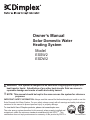
Owner’s Manual
Solar Domestic Water
Heating System
Model
ESSW2
ESDW2
!
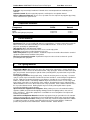
arning: This system is designed to be used with Polypropylene Glycol as a
W
heat transfer liquid. Substitution of any other heat-transfer fluid can cause irreparable damage and create a health and safety hazard.
NOTE: This manual should be kept in the same area as the system for reference
purposes.
IMPORTANT SAFETY INFORMATION: Always read this manual first before attempting to install or use this
Solar Domestic Hot Water System. For your safety, always comply with all warnings and safety instructions
contained in this manual to prevent personal injury or property damage.
To view the full line of Dimplex products, please visit www.dimplex.com
The solar energy system described in this manual, when properly installed and
maintained, meets the minimum standards established by the SRCCTM. This
certification does not imply endorsement or warranty of this product by SRCCTM.
7211690100R01
Table of Contents
Welcome & Congratulations . . . . . . . . . . . . . . . . . . . . . . . . . . . . . . . . . . . . . . . . . . . . . . . . . . . . . . . . 3
Important Instructions. . . . . . . . . . . . . . . . . . . . . . . . . . . . . . . . . . . . . . . . . . . . . . . . . . . . . . 4
Quick Reference Guide. . . . . . . . . . . . . . . . . . . . . . . . . . . . . . . . . . . . . . . . . . . . . . . . . . . . . . . . . . . . 5
General Operating Information. . . . . . . . . . . . . . . . . . . . . . . . . . . . . . . . . . . . . . . . . . . . . . . . . . . . . . 6
Single Wall Heating System. . . . . . . . . . . . . . . . . . . . . . . . . . . . . . . . . . . . . . . . . . . . . . . . . . . . . . . . 7
Double Wall Heating System . . . . . . . . . . . . . . . . . . . . . . . . . . . . . . . . . . . . . . . . . . . . . . . . . . . . . . . 8
Site Selection and Preparation. . . . . . . . . . . . . . . . . . . . . . . . . . . . . . . . . . . . . . . . . . . . . . . . . . . . . . 9
Installation Instructions. . . . . . . . . . . . . . . . . . . . . . . . . . . . . . . . . . . . . . . . . . . . . . . . . . . . . . . . . . . 12
Solar Collectors . . . . . . . . . . . . . . . . . . . . . . . . . . . . . . . . . . . . . . . . . . . . . . . . . . . . . . . . . . . . . . . . 12
Piping. . . . . . . . . . . . . . . . . . . . . . . . . . . . . . . . . . . . . . . . . . . . . . . . . . . . . . . . . . . . . . . . . . . . . . . . 15
Solar Pumping Station - Solar Loop-A. . . . . . . . . . . . . . . . . . . . . . . . . . . . . . . . . . . . . . . . . . . . . . . 15
Solar Loop Expansion Tank . . . . . . . . . . . . . . . . . . . . . . . . . . . . . . . . . . . . . . . . . . . . . . . . . . . . . . . 17
Solar Heat Transfer Liquid . . . . . . . . . . . . . . . . . . . . . . . . . . . . . . . . . . . . . . . . . . . . . . . . . . . . . . . . 18
Pumping Station - HXA (Only for use in Double Wall Systems). . . . . . . . . . . . . . . . . . . . . . . . . . . . 19
HXA Expansion Tank (Only for use in Double Wall Systems). . . . . . . . . . . . . . . . . . . . . . . . . . . . . . 20
Solar Storage Tank. . . . . . . . . . . . . . . . . . . . . . . . . . . . . . . . . . . . . . . . . . . . . . . . . . . . . . . . . . . . . . 20
Solar Controller. . . . . . . . . . . . . . . . . . . . . . . . . . . . . . . . . . . . . . . . . . . . . . . . . . . . . . . . . . . . . . . . . 21
Commissioning. . . . . . . . . . . . . . . . . . . . . . . . . . . . . . . . . . . . . . . . . . . . . . . . . . . . . . . . . . . . . . . . . 23
Heat Transfer Liquid System Filling - Polypropylene Glycol. . . . . . . . . . . . . . . . . . . . . . . . . . . . . . . 23
HXA Pumping Station Filling - Distilled Water (If Applicable). . . . . . . . . . . . . . . . . . . . . . . . . . . . . . 24
Potable Water Connection. . . . . . . . . . . . . . . . . . . . . . . . . . . . . . . . . . . . . . . . . . . . . . . . . . . . . . . . 25
Operation. . . . . . . . . . . . . . . . . . . . . . . . . . . . . . . . . . . . . . . . . . . . . . . . . . . . . . . . . . . . . . . . . . . . . . 27
Solar Collectors . . . . . . . . . . . . . . . . . . . . . . . . . . . . . . . . . . . . . . . . . . . . . . . . . . . . . . . . . . . . . . . . 27
Piping. . . . . . . . . . . . . . . . . . . . . . . . . . . . . . . . . . . . . . . . . . . . . . . . . . . . . . . . . . . . . . . . . . . . . . . . 27
Pumping Station - Solar Loop-A. . . . . . . . . . . . . . . . . . . . . . . . . . . . . . . . . . . . . . . . . . . . . . . . . . . . 27
Solar Loop Expansion Tank . . . . . . . . . . . . . . . . . . . . . . . . . . . . . . . . . . . . . . . . . . . . . . . . . . . . . . . 28
HXA Pumping Station (If Applicable) . . . . . . . . . . . . . . . . . . . . . . . . . . . . . . . . . . . . . . . . . . . . . . . . 28
HXA Expansion Tank . . . . . . . . . . . . . . . . . . . . . . . . . . . . . . . . . . . . . . . . . . . . . . . . . . . . . . . . . . . . 29
Solar Storage Tank. . . . . . . . . . . . . . . . . . . . . . . . . . . . . . . . . . . . . . . . . . . . . . . . . . . . . . . . . . . . . . 29
Solar Controller. . . . . . . . . . . . . . . . . . . . . . . . . . . . . . . . . . . . . . . . . . . . . . . . . . . . . . . . . . . . . . . . . 29
Maintenance. . . . . . . . . . . . . . . . . . . . . . . . . . . . . . . . . . . . . . . . . . . . . . . . . . . . . . . . . . . . . . . . . . . 33
Solar Collectors . . . . . . . . . . . . . . . . . . . . . . . . . . . . . . . . . . . . . . . . . . . . . . . . . . . . . . . . . . . . . . . . 33
Piping. . . . . . . . . . . . . . . . . . . . . . . . . . . . . . . . . . . . . . . . . . . . . . . . . . . . . . . . . . . . . . . . . . . . . . . . 33
Pumping Stations - Solar Loop and HXA. . . . . . . . . . . . . . . . . . . . . . . . . . . . . . . . . . . . . . . . . . . . . 33
Expansion Tanks. . . . . . . . . . . . . . . . . . . . . . . . . . . . . . . . . . . . . . . . . . . . . . . . . . . . . . . . . . . . . . . . 34
Storage Tanks. . . . . . . . . . . . . . . . . . . . . . . . . . . . . . . . . . . . . . . . . . . . . . . . . . . . . . . . . . . . . . . . . . 34
Solar Controller. . . . . . . . . . . . . . . . . . . . . . . . . . . . . . . . . . . . . . . . . . . . . . . . . . . . . . . . . . . . . . . . . 35
Decommissioning. . . . . . . . . . . . . . . . . . . . . . . . . . . . . . . . . . . . . . . . . . . . . . . . . . . . . . . . . . . . . . . 36
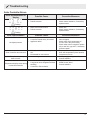
Troubleshooting. . . . . . . . . . . . . . . . . . . . . . . . . . . . . . . . . . . . . . . . . . . . . . . . . . . . . . . . . . . . . . . . 38
Warranty . . . . . . . . . . . . . . . . . . . . . . . . . . . . . . . . . . . . . . . . . . . . . . . . . . . . . . . . . . . . . . . . . . . . . 40
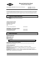
Appendix - Dowfrost HD MSDS. . . . . . . . . . . . . . . . . . . . . . . . . . . . . . . . . . . . . . . . . . . . . . . . . . . . 43
2
www.renewables.dimplex.com
Welcome & Congratulations
Dear Customer,
Thank you very much for choosing the our Solar Domestic Hot Water System. We appreciate the choice
of products you have had and we want to assure you that the Solar Hot Water System satisfy the highest
performance, quality and reliability requirements. When correctly installed, commissioned, operated and
maintained we are sure that you will enjoy many years of hot water from your Solar Hot Water System.
This document will guide you through all the necessary steps to ensure you will benefit from a long and
trouble free service of your Solar Hot Water System. The guide is structured into the following sections:
For the trained installer:
• Installation
• Commissioning
• Maintenance
• Troubleshooting
• Decommissioning
For the user:
• Operation
• Troubleshooting
• Warranty
• Contact Information
The installation, commissioning and maintenance sections of this guide are for the trained installer only.
Should any issues arise at any stage, which you do not find sufficiently covered in this document please
contact technical service using one of the means detailed below.
Wishing you lots of sunshine,
Your Technical Service Team
Contact us at:
www.renewables.dimplex.com/contact_us for Troubleshooting and Technical Support
OR Toll-Free 1-888-DIMPLEX (1-888-346-7539) Monday to Friday 8:00 a.m. to 4:30 p.m. EST
3
Important Instructions
When using electrical appliances, basic precautions should
always be followed to reduce the risk of fire, electric shock,
and injury to persons, including the following:
1. Read all instructions before using this appliance.
2. Disconnect all power supplies before performing any
cleaning, maintenance or relocation of the unit.
3. Do not modify any of the pumps. Use them only
as described in this manual. Any other use not
recommended by the manufacturer may cause electric
shock or injury to persons.
4. Do not operate the unit with any damaged cords, if any
of the pumps have malfunctioned, if the tanks or piping
have been damaged in any manner.
Disclaimer
The information presented in this manual was correct at the
time of print and was prepared with the greatest diligence
and care possible. The manufacturer does not take any
responsibility for damage done to property or life by not
adhering to the instructions given in this guide. The right is
reserved to introduce technical alterations without prior notice
as part of the company’s continuous improvement measures.
All personnel specifying or designing the use of this equipment, installing, operating or maintaining it must be appropriately trained or instructed and must follow the procedures
laid out in this guide and other related and relevant literature
including standards and regulations.
5. The Solar Hot Water System is only to be filled in its cold
condition. If required, cover the solar collector during
installation.
Warning: High temperatures of solar panels and heat
transfer solution may result in scalding!
6. Solar Hot Water Systems can absorb high temperatures.
There is a danger of burning! Be careful when installing
or inspecting the temperature sensor.
7. Consult the MSDS sheets or Safety Data Sheets for
information on the heat transfer solution before filling or
draining the system.
8. Installers of this product should follow guide lines for
safety for proper transportation and manipulation of the
solar collector on/to the roof set out by Local Health and
Safety Acts.
9. Only a trained and competent person should install this
system.
10. Dimplex does not accept any liability for damage done to
persons or property resulting from undue handling and
usage of this product.
11. All regulations current at the time of installation are to be
considered alongside the content of this manual as they
form the code of best practice.
12. It is the responsibility of the Owner/Installer to ensure
that the transport, storage, installation and operation of
the product is carried out in a safe manner.
13. When making the piping connections, make sure that
connecting pipe work is not mechanically over-stressed.
Over time this could cause breakages, with consequent
liquid losses which, in turn, could cause harm to property
and/or people.
SAVE THESE Instructions
Always use a qualified technician or service
agency to repair this system.
! NOTE: Procedures and techniques that are
considered important enough to emphasize.
CAUTION: Procedures and techniques which,
if not carefully followed, will result in damage to
the equipment.
Warning: Procedures and techniques which,
if not carefully followed, will expose the user to
the risk of fire, serious injury, or death.
4
www.renewables.dimplex.com
Quick Reference Guide
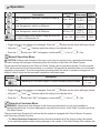
Component Check List
Kit Components
Part Number
Description
ESSW2
Qty
ESDW2
Qty
DSCA-2M
SOLAR COLLECTOR, DIMPLEX, FP BLUE-A, 2M
2
2
MK-DSCA
MOUNTING KIT, 1 X DSCA
2
2
NA12142
FITTING, UNION, COMPRESSION 3/4”
2
2
254752
FITTING, ELBOW, COMPRESSION 3/4" THREADED
2
2
DSTA-200
STORAGE TANK, DIMPLEX, SOLAR HX, 53GAL/200L
1
1
9702900
EXPANSION TANK, SOLAR LOOP, 6.6GAL/25L
1
1
45111.5 NA
CONTROLLER, MEIBES, SOLAR-A
1
1
8400410100
WIRE, CONNECTION, 6FT (1.8M)
1
1
4100170200RP
CORDSET
1
1
45722.1 NA
PUMPING STATION, MEIBES, SOLAR LOOP-A
1
1
45411.30 NA
PUMPING STATION, MEIBES, HXA
N/A
1
1002540100
BRACKET, PUMP MOUNT
1
1
NA12141
FITTING, END-STOP, COMPRESSION
2
2
7611000
MOUNTING BRACKET, EXPANSION TANK, SOLAR LOOP-A
1
1
5400250100
EXPANSION TANK, HX-A 0.5GAL/2L
N/A
1
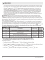
Optional Additional Components
Part Number
Description
DGA-25
POLYPROPYLENE GLYCOL, DOWFROST, 6.6GAL/25L
NA3520-15
FLEXTUBE SET, INSULATED 1/2" WITH SENSOR WIRE - 50 FT/15M
NA12102
FITTING, FLEXTUBE, 3/4"
NA12133
MOUNTING BRACKET, FLEXTUBE, SET OF 4
Qty
Qty
1-2*
1-2*
1
1
8 min..**
12 min..**
1
1
* Depending on pipe length
** Depending on number of connectors
NOTE: Reference to “A” in Description indicates that in larger systems multiples of these components may be used.
General requirements
• Electrical Water Heater tank, 50 gal (184L)
! NOTE: Water heater must have adequate capacity, listed and labeled by an accredited listing
organization.
• Competent person must install this system.
• Improper operation/installation of the unit could invalidate the warranty.
! NOTE: It is recommended that any systems with hard water have a water softener installed in
line before the Solar Hot Water System to prevent calcium build up and reduced performance of the
system.
• A predetermined location for the installation of the Solar Storage Tank and Solar Collectors.
• Tempering mixing valves, to avoid burns, are required at the outlet of the existing water heating
system or at each faucet.
• All electrical installations must be grounded.
• Make sure all piping and all equipment is clean before filling or flushing (a non-foaming detergent may be used in the Solar Hot Water System, e.g. TSP) - See Commissioning Section.
• Carefully follow the instructions and labels during the connection of the units.
5
General Operating Information
With the increasing concern for the health of our
environment and the awareness to reduce our carbon emissions, the need to use alternative sources
of energy is becoming more important. Using a
Solar Domestic Hot Water System will assist with
that and reduce your household heating costs
throughout the year. The Dimplex® Solar Domestic
Hot Water System has received US Energy Star
Rating Certification.
The Dimplex® Solar Domestic Hot Water System
uses heat transferred from the sun to specifically
designed solar collectors, with high efficiency coils
to fully optimize the heat transfer, which are located on your roof or any other southern facing surface. The panel attracts the sun’s rays and traps
them under a thick solar collector glass, increasing
the temperature of copper tubing, which is coiled
from top to bottom and heats the polypropylene
glycol mixture which is being pumped through
them, by a Solar Pumping station.
The Solar Pumping station, located within the
same area as your existing water heater, is a self
contained unit, equipped with a variable speed
pump to adjust the heat transfer speed within the
collection panels. The Solar Pumping station allows the user to monitor: the input and output temperatures of the polypropylene glycol with temperature measurement dials; the operating pressure
of the system; and the flow rate of the glycol on a
variable area rotameter. As a safety consideration
the pumping station is equipped with a Solar Loop
Expansion Tank and a pressure release valve to
compensate when the temperatures within the
system reach maximum capacity.
The Dimplex® Solar Domestic Hot Water System
comes in two different configurations, for heat
transfer, depending on Local plumbing code requirements: a Single Wall; and a Double Wall
System.
In Single Wall Systems, the polypropylene glycol
is then pumped directly from the Solar Collectors
and circulated through a heat transfer coil located
in the Solar Storage Tank to heat your household
potable water.
In Double Wall Systems, the polypropylene glycol
is then pumped through a cross flow Solar Pumping Station - HXA, transferring the heat from the
glycol to Distilled water. The distilled water is then
circulated in a coil located in the Solar Storage
Tank to heat your household potable water.
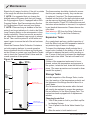
The glass lined steel Solar Storage Tank is constructed with 2.4” (60mm) of insulation to reduce
the amount of heat loss and contains a heat transfer coil to maximize the transfer of solar energy to
the water.
This Solar Hot Water System is controlled by comparing two temperature probes within the system:
one measuring the temperature at the outlet of
the Solar Collectors and one measuring the temperature of the water located in the bottom of the
Solar Storage tank. As the temperature fluctuates,
between the temperature probes, the circulation
pumps will turn on and off to transfer the fluid
throughout the system and heat the water within
the Solar Storage Tank, to the desire temperature.
The Solar Hot Water System is used in conjunction
with your existing system (Back-up). When the solar collectors are unable to provide sufficient heat
to reach set temperatures, your existing system
will supplement the generation of heat to obtain the
desired setpoint.
As an additional ability both the Solar Pumping station and the HXA Pumping Station are engineered
with a flush and fill ability. Where a portion of the
circuit can be blocked and a external pumping station can be attached to fill or drain that particular
circuit, without having to go on to the roof.
6
www.renewables.dimplex.com
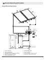
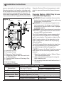
General Operating Information
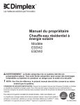
Single Wall Heating System
5
3
1
1
4
4
3
2
8
7
80
2
0
60
40
20
40
8
20
4
6
0
0 120 14
10
0
0 120 14
10
60
80
To Pressure
Relief
Collection Tank
10
5
9
6
To 120V Power Supply
Additional
Temperature
Probe Port
(Optional)
Outlet to Backup
Heating System
10
Auxiliary
Electrial
Water Tank
Inlet from Main
Water Supply
Mixing Valve
1.
2.
3.
4.
5.
Solar Collectors
Mounting Brackets
Straight Flexible Compression Fitting
Elbow Compression Fitting
Plug Compression Fitting
6.
7.
8.
9.
Solar Storage Tank
Solar Controller
Pumping Station - Solar Loop-A
Expansion Tank - Solar Loop
7
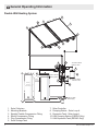
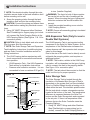
General Operating Information
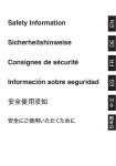
Double Wall Heating System
5
3
1
1
4
4
3
2
5
8
7
60
100
100
60
To Pressure Relief
Collection Tank
80
80
4
0
40
40
20
10
20
8
120 140
2
6
120 140
9
To 120V Power Supply
2
6
0
8
60
40
20
40
120 140
20
To Pressure Relief
Collection Tank
80
100
60
80
120 140
10
4
100
Auxiliary
Electrial
Water Tank
Additional
Temperature
Probe Port
(Optional)
12
Outlet to Backup
Heating System
10
6
11
Inlet from Main
Water Supply
Mixing Valve
1.
2.
3.
4.
5.
6.
Solar Collectors
Mounting Brackets
Straight Flexible Compression Fitting
Elbow Compression Fitting
Plug Compression Fitting
Solar Storage Tank
7. Solar Controller
8. Pumping Station - Solar Loop-A
9. Expansion Tank - Solar Loop-A
10.HXA Pumping Station (ESDW2 Only)
11.HXA Expansion Tank (ESDW2 Only)
8
www.renewables.dimplex.com
Site Selection and Preparation
Prior to installation of a Domestic Solar Hot Water
System Local Building Codes, Zoning Ordinances,
Subdivision covenants and any other special regulations pertaining to the site should be consulted.
To find out what’s needed for local compliance,
contact the following:
Your local jurisdiction’s zoning and building enforcement divisions
• Briefly describe your intended construction,
asking for other relevant ordinances/codes
that might be in effect.
• Find out if there are any additional local
amendments or modifications to the regulations in effect.
• Ask how to determine whether you are located in a historic district, flood-plain area,
or any other special category regulated by
a government body.
• Ask where you may find pertinent ordinances/codes (local library, government office,
etc.).
• Read pertinent sections of the regulations,
making photocopies of information you
wish to file for future review and design/installation analysis.
Homeowner’s, subdivision, neighborhood, and/
or community associations
• Ask if they have any ordinances, provisions, or covenants that may affect the
design and installation of the system.
• Copy and file pertinent sections for reference.
City or Municipal Offices
• Required Building Permits and associated
Inspections.
Location Considerations:
• You have determined the best south facing
roof/mounting surface with no or minimum
shading during the day. For maximum efficiency the solar collectors should be installed
in a location where they can receive 8 hours of
sunlight per day.
• The Solar Collector mounting surface is rated
to withstand the weight of the components as
well as the Fluid.
• The condition of the mounting surface has been
considered, i.e. the replacement of the shingles
would result in the need to remove and reinstall
the panels.
• You have allocated enough space for the Solar
Hot Water System installation in the same location as you current water heating system.
• The age of the current water heating system
System Considerations:
• Your household main supply of potable water is
supplied to your water heating system in accordance to applicable Plumbing Codes and
Standards.
• You have installed your auxiliary electrical storage heating system to achieve standard temperatures to applicable Plumbing Codes.
• Electrical requirements are in accordance to
Local and National Electrical Code.
• A mixing or tempering valve is present or needs
to be added.
• Local plumbing code has been consulted to
determine if additional plumbing is required on
the domestic water supply.
• The geographical location of the installation
to determine the appropriate solution required
for the system, to ensure that freeze tolerance
limits are appropriate.
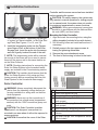
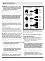
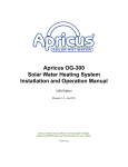
GENERAL INTRODUCTION FOR SOLAR
COLLECTOR INSTALLATION PLANNING
Solar collectors can be installed in various ways.
Consideration in the installation should include:
Figure 1
B
A
9
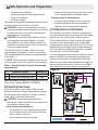
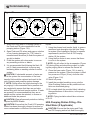
Site Selection and Preparation
The location of the Solar Controller, pumping system and storage tanks can be planned in the same
location as your current water heating system.
The Dimplex Solar Hot Water System will require
an area, in the same area as your current water
heating system, which will allow for the 24” (61cm)
diameter Solar Storage Tank with approximately 6”
(15.2cm) diameter additional clearance, to enable
easy access to monitor the system.
It is recommended that an area of wall in the same
area is available for mounting the pumping components and controller. Consideration should be
taken to ensure that it can withstand the weight of
the components and fluids. If this is not available,
the components can be mounted on a plywood
Figure 2
80
80
60
4
0
0
60
10
10
0
40
8
0
0
20
40
2
6
120 1
4
120 1
4
Installation option
Availability
A
Sloped roof vertical
Yes
B
Sloped roof horizontal (top)
Yes
Option A and B: Available with standard mounting
kit for Solar Collector ESSW2 OR ESDW2.
SYSTEM INSTALLATION AREA
20
Table 1: Dimplex Solar Collector Recommended Installation
• Routing of the pipe inside of the attic in direction of storage heater installation place.
Outside piping Considerations:
• The pipe will be visible on top of your roof.
• Ease of installation and any possibility of
leakage into the house will be avoided.
10
• Available solar radiation
• Seasonal usage of the energy demand
• Ease of installation
• Aesthetic impact
The following suggested installation orientations of
the solar collectors are shown in Figure 1.
CAUTION: Location considerations should ensure that building materials adjacent to the solar
components are not exposed to the elevated
temperatures of the system.
CAUTION: Ensure that solar collectors will not
be susceptible to excess shading. For maximum efficiency the solar collectors should be
installed in a location where they can receive 8
hours of sunlight per day.
The Dimplex Solar Hot Water System is specifically designed for shingle or steel roof mounting.
The recommended fixing options are summarized
in the Table 1.
! NOTE: There are some installations the are not
recommended, due to the specifics of this system.
PIPING ROUTING PLAN
4
2
6
0
8
10
60
40
20
0
120 1
4
40
0
10
0
120 1
4
20
80
0
60
80
10
Once the location of your Solar Collectors has
been decided, the routing of the piping to connect
the two areas can be planned. Piping can be led
either inside or outside of the house.
CAUTION: Ensure that any penetrations
through fire-rated assemblies do not reduce the
fire resistance below code.
Inside piping considerations:
• The piping will not be visible on the surface
of your house and only the Solar Collectors
will be visible on the roof.
• A roof sealing kit will be required.
ONLY USED IN ESDW2 MODEL
GLYCOL LOOP
DISTILLED WATER LOOP
10
WIRING (POWER AND SENSORS)
www.renewables.dimplex.com
Site Selection and Preparation
board or a “mounting wall”.
For the double wall system installation the wall
area required is approximately 4’ x 4’ (122 cm x
122 cm).
For the single wall system installation the wall area
required is approximately 2’ x 4’ (61 cm x 122 cm).
CAUTION: Protection against auto-ignition of
combustibles: Combustible materials used in soar
equipment and adjacent structures shall not be exposed to an elevated temperature that could cause
ignition.
CAUTION: Access to the Solar Controller, pressure relief valves and the connecting cables must
be ensured, for monitoring and maintenance of the
system.
Consideration of the location of the unit should
also allow for a 120V GFI receptacle to be located
in the same vicinity to allow for the Solar Controller
to be plugged in.
11
Installation Instructions
The Dimplex Solar Domestic Hot Water System is
designed to be installed in series to your existing
potable water heating system.
arning: This system is to be installed in
W
accordance to Local Building Codes, Electrical
Codes and National Roofing Contractors Association while following State/Provincial Health
and Safety Standard practices.
! NOTE: The Overall layout of the system can be
found in the General Operating Information Section
of this manual.
! NOTE: For space allocation requirements see
the Site Selection and Preparation section of this
manual.
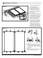
Solar Collectors
to the trusses on any roof. Figure 10 shows the
typical vertical installation, although the solar collectors can be mounted horizontally, as long as the
outlet is connected at the highest point.
CAUTION: The installation should not impair
the enclosure function of the building.
CAUTION: Ensure that all penetrations into the
building and all connections are resistant to
vermin.
! NOTE: Instructions are included to mount the
solar collectors to a support bracket located below
the trusses but longer bolts will be required (not
included).
! NOTE: Consult Local building codes as to the
type of installation that will be required.
For Mounting Collectors Directly to Trusses
Warning: Appropriate lifting practices and
appropriate Health and Safety equipment are to
be used to ensure safe transporting and installation of the solar collectors.
CAUTION: Tempered glass will shatter if handled inappropriately.
Warning: Due to the nature of the components it is suggested that the panels be covered,
during installation, to reduce the amount of
heat transfer occurring on start up and commissioning.
The Solar Collectors come with an installation kit
(Figure 3) which includes all of the components
required to mount and seal the two solar collectors
(Figure 5A)
CAUTION: Ensure that the structural members
that are being penetrated by the Solar components meet code.
1. On the surface where the solar collectors are
to be located, locate 5 studs, and mark their
centers.
! NOTE: The middle stud is not used in the installation.
2. Install the flashing under the shingles, lining
up holes in flashing to centers of the studs and
line up bottom of flashing with bottom of the
shingle. (Figure 4)
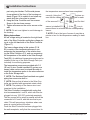
3. Using the flashing as the template drill pilot
Figure 3
7
13
8
3
6
5
1
2
15
9
14
11
10
12
4
12
www.renewables.dimplex.com
Installation Instructions
Figure 4
Figure 5
A
Figure 6
B
Figure 7
3
Figure 8
#10 Self Drilling Screw
3/8" x 2" Bolt
" x 3 Lag Screw
or 3 8" Bolt
8
3/8" Washer
Clamp
3
3
8
8
" Lock Washer
" EPDM Washer
Bracket
EPDM Gasket
Flashing (Asphalt Roofs Only)
Support Clamp
Nut Clamp
3/8" Locknut
Mounting Surface
holes using a 5/16” drill bit.
mark and drill 3/8” holes for the bolts to pass
through.
! NOTE: The flashing can be used as a template
5. On the outside surface, where the solar collectfor steel roofs but is not required as part of the
ors are to be located, locate the corresponding
installation. Flashing is required on asphalt roofs to
3 studs and mark the center points between
prevent water penetration.
them.
4. Install brackets using (2) 3/8” x 3” lag screws,
lock washer, EPDM washer, Bracket and EPDM 6. Install the flashing under the shingles, lining up
the hole in the flashing to the marks on the roof.
Gasket for each mounting location. (Figure 5)
(Figure 4).
Continue to Step 9.
For Mounting Collectors to Support Bracket 7. Using the flashing as the template drill 3/8”
holes for the bolts to pass through.
(Figure 5B)
! NOTE: The flashing can be used as a template
CAUTION: Ensure that the structural members
that are being penetrated by the Solar compon- for steel roofs but is not required as part of the
installation. Flashing is required on asphalt roofs to
ents meet code.
prevent water penetration.
1. Inside the roof, measure the distance across 3
8. Install brackets using (2) 3/8” x Bolt, Lock
trusses (from the outer most points).
Washer, EPDM Washer, Bracket and EPDM
2. Cut a 2” x 6” piece of wood corresponding to
Gasket for each mounting location. (Figure 6)
the measured length.
9. Assemble the clamping assemblies (Figure 7)
3. Mark the on the board, 3 marks that divide the
then insert them into the support brackets and
board into 4 equal sections.
tighten to 35 lbs (15.9kg) of torque.
4. Line up the flashing center on the two outside
10.Measure up 75.5” (191.8cm) and repeat Steps
marks and using the flashing as a template,
13
Installation Instructions
Figure 9
Sensor Well
Detail A
1-4 for assembly of the top
mounting assemblies.
11.Assemble the clamping assemblies (Figure 7) then
insert them into the support
brackets and tighten only to
hold in place.
12.Place each Solar Collector on
clamp assemblies, so that the
sensor wells are located on
the outside of the assembly
and the clamps are securely
resting on the brackets.
13.Connect the solar collectors
together, using the provided
Stainless Steel flexible connectors, Figure 10, which
will allow for expansion and
contraction due to changing
weather conditions and install
Figure 10
! NOTE: Plumbing connections and
plugs can be reversed, as long as
the outlets are located at the top of
the panels.
! NOTE: Only use the sensor well
that is closest to the outlet.
14
www.renewables.dimplex.com
Installation Instructions
the threaded plugs in the unused ports.
! NOTE: There are two different thickness of
shims provided to assist with ensuring that the
collectors are level and connections are sealed
properly.
14.Once the solar collectors are level and plumbed
together, secure the bottom clamp assemblies,
using #10 self drilling screws. (Figure 8)
15.Loosen the bolt in the bottom clamp and slide
into groove of the solar collector and tighten to
35 lbs (15.9kg) of torque (Figure 9 - Detail A).
16.Repeat Steps 11-15 for the top clamp assembly.
CAUTION: Ensure that the final installation of
the collectors is capable of maintaining tilt and
azimuth.
17.Install the elbow connector at the Solar Collector inlet and outlet. (Figure 10)
Piping
Two lines of 1/2” (12.7mm) piping, insulated to
R4.2 with UV resistant EPDM insulation, need to
be run from the Solar Collectors to the pumping
system. The lines can run either through the walls/
attic of the house or along the outside wall of the
house. Any piping that is required to run across a
surface horizontally should be sloped towards the
drain ports with a drainage slope of no less than
3/4” (20mm) vertical drop for each meter of horizontal length (1/4”/ft).
! NOTE: Stainless steel corrugated pipe is suggested for use but standard insulated potable
compliant piping can be used.
! NOTE: Stainless steel corrugated piping is
available as an optional accessory, in 50’ (15.24m)
lengths, with sensor wire and insulation.
! NOTE: If soldering rigid connections, ensure
soldered connections meet potable water requirements and can withstand high temperatures.
! NOTE: Tag the inlet and outlet of the piping at
each end to help with installation.
The Stainless steel corrugated piping is equipped
with a sensor wire that can be attached to the
Solar Controller and the temperature probe at the
Solar Collectors. If using an alternative piping,
double insulated 20 ga two core sensor wire can
be used and should be covered with the UV resistant insulation, with a minimum rating of R-4.2, to
protect the wire from environmental elements and
vermin.
! NOTE: When running piping ensure that the
pipe is supported properly to prevent any sagging
or stress on any other component of the system,
and has been installed with the correct pitch to allow for proper drainage.
CAUTION: When installing piping supports
ensure that the insulation is not pinched or compressed, which may damage or reduce the life of
the insulation and subsequently the piping.
In the Sensor wells, in the Solar Collectors, there is
a rubber gasket.
• Remove the gasket and insert the probe
through the gasket.
• Insert the probe into the sensor well so that the
probe gently touches the end of the well.
• Move the gasket so that it seats back into the
well and secures the temperature probe.
CAUTION: Flashing, sealing and routing for the
piping and sensor wire is the responsibility of the
installer and is not included in the kit.
When running piping from Solar Collectors to
Pumping Stations ensure that the vertical runs
of piping are supported at a minimum every 10ft
(3m).
Solar Pumping Station - Solar Loop-A
Warning: Always completely disconnect the
device from the power supply before performing
maintenance or electrical work.
Warning: Do not make any changes to electrical components, the design or the hydraulic
components to prevent risks or harm to people
or material property.
Warning: Wiring procedures and connections
should be in accordance with the National Electric code (NEC) and local codes
15
Installation Instructions
CAUTION: The pumping stations described are
to be operated as described in these instruction
with the recommended solar heat transfer liquid.
(See Heat Transfer Liquid Section for specific information)
CAUTION: Do not make any changes to electrical components, the design or the hydraulic com-
Figure 11
From Solar
Collectors
D
To Solar
Collectors
F
Glycol Overflow
D
80
4
0
0
60
10
10
60
80
2
0
40
20
20
8
10
40
6
0
0
120 1
4
120 1
4
To Expansion
Tank
J
G
A
H
K
B
C
I
H
E
To Heat
Exchanger
From Heat
Exchanger
A. Insulation Housing
B. Circulation Pump
C. Air Separator
D. Temperature Dials & Shut-off Ball Valves
with built-in Check Valves
E. Volume Flow Indicator
F. Pressure Relief Valve and Discharge Pipe
G. Pressure Gauge
H. Flush and Fill Connections
I. Isolating Ball Valve
J. Expansion Tank Connection
K. Air Separator
ponents. Any other use not recommended by the
manufacturer may cause electric shock or injury to
persons.
Warning: Improper ventilation will result in
pressure loss and can cause malfunctions in
the Solar Hot Water System. The temperatures
of the leaking air and the heat transfer medium
may be higher than 140°F (60°C). Therefore,
there is a risk of scalding. The vent is located at
the highest point of the system. Once the system has been carefully and properly ventilated,
the system pressure must be increased to the
operating pressure again.
The Solar Pumping Station - Solar Loop-A is delivered as a preassembled system. The expansion
tank and pressure relief valves are included as
separate components and installation instructions
can be found in the corresponding sections.
The unit is comprised of: a 3-way directional distributor that incorporates a manually adjustable
non-return and isolating ball valve together with
an over pressure relief valve (87 psi/6 bar) (Figure
11F); a connection point for a solar rated expansion tank (Figure 11J); an isolating ball valve, that
is fitted above the volumetric flow meter (Figure
11H), complete with flow and return filling points
with dedicated isolating ball valves for system
commissioning purposes; the ‘flow’ line incorporates a further manually adjustable non-return and
isolating ball valve at the temperature head and
also features a permanent ‘air separator’ (Figure
11C); and a 2 part EPP insulated cover.
The system must be installed on a load-bearing
wall, in a dry location. The location, relative to the
HXA Pumping station, will be dependant on the
type of piping used to connect the two pumping
stations together.
Specifications for Pumping Station - Solar Loop-A
3/4” MNPT
Connections
Solar circuit for expansion tank
3/4” MNPT
Thermometer
Display Range 70 - 300 °F (20 - 150 °C)
Pressure Gauge
Display Range 0 - 150 psi (0 - 10 bar)
Pressure Relief Valve Activation Pressure 87 psi (6 bar)
16
www.renewables.dimplex.com
Installation Instructions
Figure 12
80
80
60
0
0
60
10
10
4
0
10
40
40
20
8
0
0
20
2
6
120 1
4
120 1
4
4
2
6
0
8
10
60
40
20
0
120 1
4
0
120 1
4
40
0
10
0
20
80
10
60
80
ONLY USED IN ESDW2 MODEL
GLYCOL LOOP
DISTILLED WATER LOOP
WIRING (POWER AND SENSORS)
CAUTION: Hazards caused by neighboring
building components, electrical, gas, water, or
heating pipes must be prevented.
1. Select the installation location. Refer to Figure
12 for recommended layout.
! NOTE: Access to the Solar Controller, pressure
relief valves, and the connecting cables must be
ensured.
2. Align and mark the mounting holes using the
back insulation shell.
3. Drill mounting holes and install wall anchors, if
necessary.
! NOTE: Run electrical cables through the outer
insulation access holes in the back insulation shell
before mounting unit to wall.
4. Secure the insulation shell and mounting bracket to the wall and into the mounting holes.
CAUTION: Connect all piping and ensure there
are no leaks before making any electrical connections.
5. Connect the Solar Collector piping to the top
portion of the Solar Pumping Station (Figure
11).
! NOTE: Instructions for piping connections to the
HXA Pumping Station unit can be found in the HXA
Pumping Station installation section, if applicable.
6. The Solar Pumping station requires two additional components to ensure safe and hazard
free operation:
• Expansion Tank - See Solar Loop Expansion Tank section for Installation Instructions.
• Pressure relief collection container - It is recommended to have a container 0.26 gal (1L)
in size - Installer Supplied.
! NOTE: The pressure relief valve is factory set to
87 psi (6 bar).
Warning: The liquid in both of these containers can be hot and the risk of scalding will be
present. When choosing the type of piping and
collection container this should be taken into
account.
Warning: The liquid being collected is high
pressure and high temperature polypropylene
glycol and all associated safety precautions
should be exercised.
CAUTION: To operate the system, the Flush
and Fill ball valves must be completely closed (Figure 11H) - See Commissioning Section for additional operational instructions.
CAUTION: Refer to tank labels and valve labelling for proper fluid flow directions.
7. See Solar Controller Installation section for Wiring Instructions.
8. Install the provided insulating cover onto the
solar pumping station.
! NOTE: Ensure all connecting piping is insulated
to reduce heat loss.
Solar Loop Expansion Tank
The Solar Loop Expansion Tank is an important
safety component to the Solar Domestic Hot Water
System. As the temperature of the Polypropylene
Glycol increases the volume does as well, the
Solar Loop Expansion Tank compensates for this
17
Installation Instructions
change. When deciding on the location for this
component, the continuous fluctuations in volume/
weight needs to be taken into consideration, as the
volume/weight of the tank will change throughout
the day.
CAUTION: To ensure the maximum life of the
Solar Loop Expansion Tank do not use a solution with a higher concentration than 50% v/v
polypropylene glycol. If a higher concentration
is required due to the area in which you live, an
alternative Expansion Tank is suggested with a
diaphragm with a higher concentration rating.
1. Determine the general location for mounting the
Solar Loop Expansion Tank, ensuring that it is a
close as possible to the Solar Pumping Station.
! NOTE: The location, relative to the Solar Pumping station, will be dependant on the type of piping
used to connect the tank to the pumping station.
CAUTION: When installing ensure that no additional loads are applied to pipelines or equipment.
2. Mark the location of the mounting holes.
3. Drill mounting holes and install wall anchors, if
necessary.
4. Included with the tank is a mounting bracket
(Figure 13) to mount the tank to the wall off of
the floor. Secure the bracket with screws to the
mounting surface.
5. Mount the tank in the bracket, ensuring that the
mounting bracket is located between the two
protruding lines on the tank.
! NOTE: The tank should be mounted so that the
outlet is at the top for proper operation.
6. Secure the bracket by tightening the gear
clamp on the screw.
7. Connect with piping the Solar Loop Expansion
Tank connection on the Solar Loop Pumping
Station (Figure 11J)
Figure 13
arning: The liquid being collected is high
W
pressure and high temperature polypropylene
glycol, all associated safety precautions should
be exercised.
Solar Heat Transfer Liquid
arning: Read Safety Data Sheets /
W
MSDS data sheets before handling
liquid. Follow all personal protection and handling and storing requirements.
Warning: This system is designed to be
used with Polypropylene Glycol as a heat
transfer liquid. Substitution of any other
heat-transfer fluid can cause irreparable
damage and create a health and safety hazard.
Warning: The transfer liquid can reach
or exceed temperatures of 60°C/140°F and
poses the risk of scalding.
To ensure maximum heat absorption into the Solar
Water Heat Transfer system it is suggested that a
Polypropylene Glycol solution of 50% by volume
with water with liquid inhibitors is used for areas
where the average freezing temperature does not
exceed 30°F (-34°C). Any solution that is used in
the system is recommended to be GRAS compliant. Dimplex offers a Polypropylene Solution that is
50% v/v which will be appropriate for most installations, the MSDS sheet is attached in Appendix 1,
for reference.
! NOTE: Document the manufacturer and type of
the Solar Heat Transfer solution, because under
certain circumstances, the solar fluid should not be
mixed with agents from other manufacturers.
CAUTION: To ensure the maximum life of the
Solar Loop Expansion Tank do not use a solution with a higher concentration than 50% v/v
polypropylene glycol. If a higher concentration
is required due to the area in which you live, an
alternative Expansion Tank is suggested with a
diaphragm with a higher concentration rating.
CAUTION: Ensure the liquid has an adequate
antifreeze content.
CAUTION: Freeze tolerance limits are based
18
www.renewables.dimplex.com
Installation Instructions
upon an assumed set of environmental conditions.
Extended periods of cold weather, including ambient air temperatures above the specified limit, may
cause freezing in exposed parts of the system. It
is the owner’s responsibility to protect the system
in accordance with the Supplier’s instructions (see
Figure 14
From PGA
To PGA
Pumping Station
Pumping Station
E
F
Glycol Overflow
4
2
6
0
8
H
Expansion
C To
Tank
10
G
H
B
80
60
40
20
40
20
120 1
4
0
0
0
120 1
4
10
0
D
10
60
80
D
To Storage
Tank
A
From Storage
Tank
A. Insulation Housing
B. Circulation Pump
C. Expansion Tank Connection
D. Temperature Dials & Ball Valves with builtin Check Valves
E. Pressure Relief Valve and Discharge Pipe
F. Flat Plate
G. Pressure Gauge
H. Flush and Fill Valves
Connections
Thermometer
Pressure Gauge
Pressure Relief Valve
Medium
Operation Section) if the air temperature is anticipated to approach the specified freeze tolerance
limit.
Pumping Station - HXA (Only for use
in Double Wall Systems)
Warning: Always completely disconnect the
device from the power supply before performing
maintenance or electrical work.
Warning: Do not make any changes to electrical components, the design or the hydraulic
components to prevent risks or harm to people
or material property.
Warning: Wiring procedures and connections
should be in accordance with the National Electric code (NEC) and local codes
The HXA Pumping Station comes preassembled.
The system must be installed on a load-bearing
wall, in a dry location. The location, relative to the
Solar Pumping station, will be dependant on the
type of piping used to connect the two pumping
stations together.
The HXA Pumping Station transfers the heat from
the Polypropylene Glycol to Distilled water that
circulates through the Solar Storage Tank.
! NOTE: Access to the Solar Controller, pressure
relief valves and the connecting cables must be
ensured.
1. Select the installation location. Refer to Figure
12 for recommended layout.
2. Align and mark the mounting holes using the
back insulation shell.
3. Drill mounting holes and install wall anchors, if
necessary.
Specifications for HXA Pumping Station
3/4” MNPT to Solar Storage Tank
Solar circuit (Primary)
3/4” MNPT to Expansion Tank
Display Range 70 - 300 °F (20 - 150 °C)
Display Range 0 - 150 psi (0 - 10 bar)
Activation Pressure 87 psi (2 bar)
Solar Circuit (Primary)
Approved Solar Heat Transfer Liquid
Storage Circuit (Secondary)
Distilled Water
19
Installation Instructions
! NOTE: Run electrical cables through the outer
insulation access holes in the back insulation shell
before mounting unit to wall.
4. Screw the pumping station through the back
insulation shell and into the mounting holes.
CAUTION: Connect the piping and ensure there
are no leaks before making any electrical connections.
5. Using 3/4” MNPT fittings and either Stainless
Steel Flexible/rigid or copper piping (not included), connect the Solar Pumping Station to the
HXA Pumping Station (See Figures 11 & 14 for
connection points).
CAUTION: Refer to tank labels and valve markings for proper fluid flow directions
! NOTE: See Solar Storage Tank and Expansion
Tank Installation Instructions for additional piping
and see Solar Controller Installation section for
Wiring Instructions.
6. The HXA Pumping station requires two additional components to ensure safe and hazard
free operation:
• HXA Expansion Tank - See HXA Expansion
Tank section for Installation Instructions.
• Pressure relief collection container - It is recommended to have a container 0.26 gal (1L)
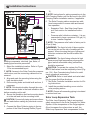
Figure 15
Anode Rod
Pressure Relief Valve
Potable Water
Outlet (3 4" NPT)
Top
Temperature
Sensor Well
Heat Exchanger
Water Inlet
(3 4" NPT)
Bottom
Temperature
Sensor Well
Heat Exchanger
Water Outlet
(3 4" NPT)
Potable Water Inlet
(3 4" NPT)
Drain
in size. (Installer Supplied)
Warning: The liquid in both of these containers can be hot and the risk of scalding will be
present. When choosing the type of piping and
collection container this should be taken into
account.
7. Install the provided insulating cover onto the
HXA Pumping Station.
! NOTE: Ensure all connecting piping is insulated
to reduce heat loss.
HXA Expansion Tank (Only for use in
Double Wall Systems)
The HXA Expansion Tank is an important safety
component to the Solar Hot Water System. As the
temperature of the Distilled water increases the
volume does as well, the expansion tank compensates for this change.
Due to the size of the tank it can be directly mounted beside the pumping station, and requires no
additional support.
! NOTE: The location, relative to the HXA Pumping station, will be dependant on the type of piping
used to connect the tank to the pumping station.
See Figure 14 for connection point.
! NOTE: The tank should be mounted so that the
outlet is at the top for proper operation.
Solar Storage Tank
The Solar Storage Tank is heated through the
circulation of the heated fluid (the type of fluid is
dependent on the system that you have installed Glycol or Distilled Water) through a heating coil located within the tank. The domestic potable water
fills the tank which contains a temperature probe,
located at the bottom of the tank. The temperature
difference is measured between the Solar Collectors and the Solar Storage tank and compared
to the set point. If there is a temperature offset
between the two the Solar Controller starts the
Pumping Stations.
1. Using 3/4” MNPT fittings and either Stainless
Steel Flexible/rigid or copper piping (not included), connect the Solar Pumping Station or
20
www.renewables.dimplex.com
Installation Instructions
Figure 16
HXA Pumping Station - depending on the type
of system you have installed - to the Solar Storage Tank (See Figures 11 or 14, and 15)
2. Install the temperature probe into the Temperature Sensor Well, at the bottom of the Solar
Storage Tank. Insert the probe into the sensor
well until it gently touches the end of the well.
! NOTE: The temperature probe will be inserted
far enough in that there will be no need to secure
them into the sensor well in the same fashion as
on the Solar Collector.
! NOTE: Plumbing instructions for connecting the
Solar Hot Water System to the household water
supply are included in the Commissioning section.
CAUTION: The installer should ensure that the
Solar Hot Water System is fully setup and functioning correctly before connecting the Solar Hot
Water System to the Household water supply.
Controller and the secure screw has been installed
before operating the system.
CAUTION: For safety reasons, the system may
only remain in manual operation for testing purposes. In manual mode, the system does not monitor
for maximum temperatures or sensor functions.
Warning: Wiring procedures and connections
should be in accordance with the National Electric code (NEC) and local codes.
Mounting the Solar Controller
1. Align and mark the mounting holes, using the
drilling template (included in box with device).
2. Drill mounting holes and install wall anchors, if
necessary.
3. Partially screw in the two upper screws, allowing for tightening afterwards.
4. Remove the cover attachment screw.
5. The front of the housing is locked to the back
Figure 17
Solar Controller
Warning: Always completely disconnect the
device from the operating voltage before performing installation or wiring work on the electrical equipment.
Warning: Never mix up the connections of
the protective low voltage areas (temperature
sensors) with the 120V connections (pump outputs).
CAUTION: The Solar Controller is neither
splash-proof, nor drip-proof, ensure that it is
mounted in an area where it will not be exposed to
excess moisture.
CAUTION: Ensure that the cover of the Solar
PE
L
N
A1
Ground Wire
Line In from Electrical Plug
Neutral from Electrical Plug
Line Out - Pumping Station Control
(both pumps)
N Neutral Out - Pumping Station Control
(both pumps)
S1 Solar Collectors Temperature Sensor
S2 Bottom Solar Storage Tank Temperature
Sensor
S3 Top Solar Storage Tank Temperature Sensor
(Not Included)
21
Installation Instructions
part using two latches. Pull the side pieces
(cover plates) of the front of the housing outwards (Figure 16) to unlatch it and rotate upwards until the cover plate is opened.
6. Hang the Solar Controller onto two screws.
Screw in the two lower screws.
7. Tighten all screws so the unit is secure on the
wall.
! NOTE: Do not over tighten to avoid damage to
the housing.
Wiring Instructions
All low voltage wiring is located on the right hand
side of the Solar Controller and higher voltage wiring is on the left hand side of the Solar Controller.
(Figure 17)
The lower voltage wiring in this system (S1 &
S2) consists of two temperature sensors: one
measuring the temperature of the solution leaving the Solar Collectors (S1), and one measuring
the temperature of the water in the Solar Storage
Tank (S2). An additional temperature probe can be
installed in the top of the Solar Storage Tank (not
included) for monitoring purposes.
The temperature sensors are provided with 3 ft
(90 cm) of wire. Double insulated 20 ga two core
sensor cable can be used to extend the cable to
install the temperature probe to the solar collectors
or the Solar Storage tank.
! NOTE: The Stainless Steel insulated corrugated
piping has sensor wire built in.
! NOTE: Ensure that all wires to the Solar Controller are installed with appropriate strain reliefs.
! NOTE: The polarity of the sensor wire is not
important to the installation.
The Solar Controller is supplied with a plug that
is to be connected to L and N, which can then be
plugged into any 120V GFI protected receptacle.
The two pumps will be wired in parallel and will be
connected to A1 and N, with the wire that is provided. This will prevent any situations where one
pump is running without the other.
Once the Solar Controller has been plugged into
the wall receptacle, verify that the connections for
the temperature sensors have been completed
correctly. Using the
and
buttons ensure that the values are being displayed for each
of the sensors S1 (
), S2 (
) and if a third
). If the
icon is
sensor is installed S3 (
present there is an issue with the corresponding
sensor.
! NOTE: Due to the type of sensor it may take a
minute or two for the temperature reading to stabilize.
22
www.renewables.dimplex.com
Commissioning
arning: The initial start-up must be carried
W
out by a trained, qualified person and must be
recorded in writing. The technical documentation must be kept with the equipment.
CAUTION: The installer should ensure that the
Solar Hot Water System is fully setup and functioning correctly before connecting the Solar Hot
Water System to the Household water supply.
Before proceeding to fill the system verify that all
plumbing connections have been installed and
tightened, all electrical connections have been
made, all of the required flashing has been installed and all piping insulated with UV resistant
insulation.
There are manual valves incorporated into the
Solar Loop Pumping Station as well as the HXA
Pumping Station to allow for filling and draining of
the system.
Shut-off ball valves
The Shut-off ball valves (Figure 11D and Figure
14D) are equipped with integrated check valves
that can be set by hand. The arrow on the spindle
indicates the flow direction or position (Figure 18).
CAUTION: The shut-off ball valves must only be
activated by trained Operators. Failure to observe
the flow direction can result in the check valve
working against the intended flow direction and, as
a result, blocking the flow and possibly damaging
the system.
Valve settings with activated backflow preventers
are (Figure 18):
• Open - Normal Operation - the arrows are vertical, depending on the direction of flow.
• Open - Flushing & Filling - the arrows are set at
45° angle, to disable the backflow preventer to
allow to fill the entire system.
• Closed - the arrows are horizontal to prevent
any flow through the valves - should only be
used during maintenance functions.
Lower shut-off valve (Only on the Solar Pumping Station)
The lower shut-off valve is integrated in the small
distributor where filling/emptying tap is located,
Figure 18
- Normal Operation
1 Opened
(Check Valve Active)
Note flow direction, which is
marked by an arrow!
To Solar
Collectors
From Solar
Collectors
2
Opened - Flushing & Filling
(Check Valve Inactive)
To Solar
Collectors
From Solar
Collectors
3
Closed
To Solar
Collectors
From Solar
Collectors
above the flow meter (Figure 19 or Figure 11I).
When the valve is set between position 1 and 2,
the shut-off valve is a volume flow limiter through
the solar pumping station.
Heat Transfer Liquid System Filling Polypropylene Glycol
arning: Read MSDS data sheets beW
fore handling liquid. Follow all
personal protection and handling
and storing requirements.
CAUTION: Due to the nature of the components it is suggested that the panels be covered
during installation, and filling to be performed
during the morning or evening hours to reduce
the amount of heat transfer and subsequent
hazard of scalding occurring on commissioning
and start up.
1. On the Solar Pumping Station, rotate the Shutoff Ball valves (Figure 11D), to the Flushing &
Filling Position (Position 2 - Figure 18).
2. Close the Isolating ball valve (Figure 11I) located above the flow meter. (Position 1 on Figure
19)
23
Commissioning
Figure 19
1
2
Closed for Filling/Flushing
3
Open Normal Operation
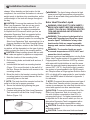
3. Attach the Flush and Fill Pumping system to
the Flush and Fill valve connections on the
pumping station (Figure 11H).
4. Open Flush and Fill valves and pump a solution
of non-foaming detergent (i.e. TSP, mixed to
manufacturers directions) to flush the system of
any dirt or debris.
5. Flush the system with clean water to remove
any remaining solution or debris.
6. It is recommended that following the flush, 50
psi (3.4 bar) pressurized air to remove any
remaining water or washing solution from the
system.
CAUTION: If substantial amounts of water are
left in the system the concentration of the heat
transfer fluid would be reduced and result in the
risk of freezing and possible system damage.
! NOTE: During either the liquid cleaning or the
air purging it is recommended that a pressure test
be completed to ensure that there are no leaks
before filling with the heat transfer solution. If leaks
are present it is recommended that they are repaired and the system be retested, to ensure no
additional leaks are present.
CAUTION: Wear all personal protective clothing
required by MSDS Sheets.
CAUTION: Ensure that the Flush & Fill pumping
station has been thoroughly cleaned to ensure no
cross contamination or dilution of the heat transfer
Closed for Pump Replacement
liquids.
7. Using the chosen heat transfer liquid, to ensure
maximum heat absorption into the Heat Transfer system (See Installation Section for specific
requirements) and the Flush & Fill Pumping
station, fill the system.
8. Using the flow meter to see, ensure that there
is no air in the system.
! NOTE: Air will collect in the air separator (Figure
11K) during filling and should be purged, by opening the purging valve to release the excess air.
9. Close the lower valve (Figure 11H) to start to
pressurize the system. Once the system is filled
to a pressure of 29 psi (2 bar), close the inlet
valve (Figure 11H).
10.Switch off pump.
11.Install the provided insulating cover onto the
Solar Pumping Station and any additional insulation on associated piping.
12.Fill out and attach the provided label, indicating
the specifications of the solution, to the pumping station.
! NOTE: Piping insulation should be a minimum
of R-4.2.
HXA Pumping Station Filling - Distilled Water (If Applicable)
CAUTION: Ensure that the piping and Flush
and Fill Pumping station has been thoroughly
24
www.renewables.dimplex.com
Commissioning
cleaned to ensure that there is no cross contamination of the heat transfer liquids
1. On the HXA Pumping Station, rotate the Shutoff Ball valves (Figure 14D), to the Flushing &
Filling Position (Position 2 - Figure 18).
2. Attach the Flush and Fill Pumping system to
the Flush and Fill valve connections on the
pumping station (Figure 14H).
3. Open Flush and Fill valves and pump a solution
of non-foaming detergent (i.e. TSP, mixed to
manufacturers directions) to flush the system of
any dirt or debris.
4. Flush the system with clean water to remove
any remaining solution or debris.
5. It is recommended that following the flush, 50
psi (3.4 bar) pressurized air to remove any remaining washing solution in the system.
! NOTE: During either the liquid cleaning or the
air purging it is recommended that a pressure test
be completed to ensure that there are no leaks
before filling with the heat transfer solution. If leaks
are present it is recommended that they are repaired and the system be retested, to ensure no
additional leaks are present.
6. Using Distilled Water and the Flush & Fill
Pumping station, fill the system.
7. Once the system is filled, return the valves to
their original state.
8. Switch off Pump.
9. Install the provided insulating cover onto the
HXA Pumping station and any additional insulation on associated piping.
! NOTE: Piping insulation should be a minimum
of R-4.2.
Potable Water Connection
arning: This system is to be installed in acW
cordance to applicable Plumbing Codes.
When installing the Dimplex Solar Water Heater
system additional plumbing will need to be added
to your existing water system. (Figure 20)
! NOTE: Depending on local plumbing codes the
system may require the addition of a backflow preventer on the supply water inlet.
arning: If a backflow preventer is installed
W
in the system an expansion vessel will also be
required to allow for the changing volume/pressure within the closed system.
1. Pipe your potable water through an isolation
valve to the inlet of the Solar Storage Tank (the
bottom fitting).
! NOTE: It is recommended that any systems
with hard water have a water softener installed in
line before the Solar Hot Water System to prevent
calcium build up and subsequently reduce the performance of the system.
Figure 20
Cold Water
Existing
Heating
System
Heated Water
T
Solar Storage
Tank
Supply
Water
T
Expansion
Tank
Anti-Scalding
Valve
Isolation
Valve
Backflow
Preventer
25
Commissioning
! NOTE: The cold water supply line to the Solar
Storage tank should be insulated with R-4.2, 1”
(2.5cm) thick, for a minimum distance of 5’ (1.5m)
or to the wall if it is less than 5’ (1.5m).
2. Install an isolation valve on the outlet of the
Solar Storage Tank and add a Tee connection
to the existing piping into the existing water
heating system.
3. Install an Anti-Scalding valve on the outlet of
the backup water heating systems before distribution throughout the house.
! NOTE: Anti-Scalding valves should be installed
to reduce the point of use water temperature by
mixing hot and cold water in branch water lines at
the outlet of the heaters.
4. Close the bypass valve and open the isolation
valves on either side of the Solar Hot Water
System.
5. Open two faucets.
6. Open the main shut off valve and let the water
run until full streams are coming out of both
open water faucets. Close both faucets.
7. Actuate the pressure relief valve located on the
top of the Solar Storage Tank and the Back-Up
Heating System until water comes out of both,
to ensure that they are full of water and free of
air.
• Verify that the main water supply has been
turned back on.
• When the Solar Collector has been turned on
and the system is running the pump icon
(
) should be On and turning in the bottom
left hand corner and both of the pumps running.
After the system has been started (and the installer
is satisfied that it is operating properly) complete
the warranty registration, found at the end of this
manual.
System Start Up
Once all of the piping has been filled with the associated liquid, and the system has been checked
for leaks, the system can be started.
• Rotate all of the manual valves from the flushing and filling setting to the operational settings.
• Actuate the air separator to ensure that any accumulated air is removed.
! NOTE: If there is some air accumulated, open
the air separator long enough to release the air.
Then run the system for a little while and open
it again to ensure that all of the air has been removed.
• Ensure that the Solar Controller is in automatic
operation.
• Verify that covers (if used) have been removed
from the solar collection panels.
26
www.renewables.dimplex.com
Operation
arning: If the outdoor temperaW
ture is expected to drop below the
rated temperature range of the
heat transfer liquid, drain the heat
transfer liquid out of the system
until the threat is no longer present.
Solar Collectors
There is no specific operator action required.
Piping
There is no specific operator action required.
Pumping Station - Solar Loop-A
arning: CHECK THAT ALL VALVES ARE
W
ORIENTED IN THE APPROPRIATE DIRECTION BEFORE STARTING THESE INSTRUCTIONS. see figures 18 & 19.
Warning: This system is designed to be used
with Polypropylene Glycol as a heat transfer
liquid. Substitution of any other heat-transfer
fluid can cause irreparable damage and create
a health and safety hazard.
Warning: The housing of the motor and any
uninsulated piping will be hot during operation.
To avoid burns, do not let bare skin touch hot
surfaces.
The circulation pumps on the Solar Pumping Station and the HXA Pumping Station are controlled
by the comparison of temperatures of the temperature probe in the Solar Storage Tank and the
temperature probe at Solar Collectors. The Solar
Controller turns the pumps On and Off and adjusts
the speed, of both, to maximize the efficiency of
the system and the result is a totally automated
system where periodic monitoring is all that is
required.
The Solar Controller will display the symbol
,
indicating that the pumps are On.
CAUTION: Both pumps should be running at
the same time, if only one pump is running disconnect power to the system and troubleshoot the
issue.
! NOTE: In general a lower flow rate will result in
a higher heat transfer rate throughout the system,
leading to higher temperatures.
• Pressure Relief Valve
The pumping station is equipped with a pressure relief valve. The activation pressure of the
pressure relief valve is 87 psi (6 bar).
Although the valve is set for 87 psi (6 bar) as the
pressure release, the normal operation of the
unit will be 58 psi (4 bar).
Warning: The supplied pressure relief
valve must be permanently installed at the intended position of the solar pumping station.
• Check Valves
When the system is not operating, the Check
Valves in the pumping station prevent the uncontrolled circulation of the heat transfer medium. They are located in the Shut-off Ball Valves
in the supply and the return lines in each pumping station.
CAUTION: The shut-off ball valves must only
be activated by trained Operators. Failure to observe the flow direction can result in the check
valve working against the intended flow direction
and, as a result, blocking the flow and possibly
damaging the system.
They should only be opened manually (Figure
18) by adjusting the ball valves 45° clockwise,
from the open operating position, for filling and
draining the system or closed for maintenance
to prevent any flow of solution.
• Flow Meter
The pumping station is equipped with a rotameter to monitor the flow through the unit. The
Solar Controller varies the speed of the pumps
to maximize the heat transfer through the system. As a result the flow meter will typically read
between 0.7gpm and 1.2 gpm.
The flow rate of the Solar Heating Water System
varies to optimize the energy gain from the solar
collector into the cylinder. However, should the
flow meter on the solar pumping station indicate
a flow outside that range, the troubleshooting
guide should be consulted as a malfunction ex27
Operation
ists.
! NOTE: If there is some air accumulated,
open the air separator long enough to release
the air. Then run the system for a little while and
open it again to ensure that all of the air has
been removed.
• Temperature Gauges
The system is equipped with two temperature
gauges to monitor the temperature of the fluid
travelling to and from the Solar Collector Panels.
The color of the printing on the dial indicates
the direction of flow to assist in monitoring the
system:
• Red lettering = SP (from the Solar Collectors)
• Blue lettering = RT (to the Solar Collectors)
The range of the gauges is 70 - 300 °F (20 - 150
°C).
Solar Loop Expansion Tank
There is no specific operator action required.
HXA Pumping Station (If Applicable)
arning: CHECK THAT ALL VALVES ARE
W
ORIENTED IN THE APPROPRIATE DIRECTION BEFORE STARTING THESE INSTRUCTIONS. See Figure 19
Warning: The housing of the motor and any
uninsulated piping can be hot during operation.
To avoid burns, do not let bare skin touch hot
surfaces.
The circulation pumps on the Solar Pumping Station and the HXA Pumping Station are controlled
by the comparison of temperatures of the temperature probe in the Solar Storage Tank and the
temperature probe at Solar Collectors. The Solar
Controller turns the pumps On and Off and adjusts
the speed, of both, to maximize the efficiency of
the system and the result is a totally automated
system where periodic monitoring is all that is
required.
,
The Solar Controller will display the symbol
indicating that the pumps are On.
CAUTION: Both pumps should be running at
the same time, if only one pump is running discon-
nect power to the system and troubleshoot the
issue.
• Pressure Relief Valve
The pumping station is equipped with a pressure relief valve. The activation pressure of the
pressure relief valve is 29 psi (2 bar).
Although the valve is set for 29 psi (2 bar) as the
pressure release, the normal operation of the
unit will be 14.5 psi (1 bar).
Warning: The supplied pressure relief
valve must be permanently installed at the intended position of the solar pumping station.
• Check Valves
When the system is not operating, the Check
Valves in the pumping station prevent the uncontrolled circulation of the heat transfer medium. They are located in the Shut-off Ball Valves
in the supply and the return lines in each pumping station.
CAUTION: The shut-off ball valves must only
be activated by trained Operators. Failure to observe the flow direction can result in the check
valve working against the intended flow direction
and, as a result, blocking the flow and possibly
damaging the system.
They should only be opened manually (Figure
18) by adjusting the ball valves 45° clockwise,
from the open operating position, for filling and
draining the system or closed for maintenance
to prevent any flow of solution.
• Temperature Gauges
The system is equipped with two temperature
gauges to monitor the temperature of the water
travelling to and from the Solar Collector Panels. The color of the text on the dial indicates
the direction of flow to assist in monitoring the
system:
• Red lettering = SP (from the Solar Pumping
Station)
• Blue lettering = RT (to the Solar Pumping Station)
The range of the gauges is 70 - 300 °F (20 150 °C).
28
www.renewables.dimplex.com
Operation
HXA Expansion Tank
There is no specific operator action required.
Figure 22
Solar Storage Tank
Main Menu
The Solar Storage Tank is equipped with a pressure relief valve. The activation pressure of the
pressure relief valve is 29 psi (2 bar).
Although the valve is set for 29 psi (2 bar) as the
pressure release, the normal operation of the
unit will be 14.5 psi (1 bar).
Warning: The supplied pressure relief valve
must be permanently installed at the intended
position of the Solar Storage Tank (Figure 15).
Solar Controller
CAUTION: Ensure that the cover of the Solar
Controller and the secure screw has been installed
before operating the Solar Controller.
Figure 21
Button
Function
Description
• Value change: increase of the indicated
value by 1, holding the button causes
the value to increase continuously
• Access a main menu, decrease menu
“Access”
items
“Down”
• Value change: decrease of the indi“-”
cated value by 1, holding the button
causes the value to increase faster
• In main menu scroll to the left
“Scroll left” • Exit a menu
“Exit”
• Exit a menu item
“Cancel” • Cancel value change without saving
the value
• In main menu scroll to the right
“Scroll right”
• Select a menu item
“Select”
• Confirmation of value change and sav“Confirm”
ing the value
“Up”
“+”
Display Values
Measuring Points
Assignments
Status Indication
Once the Dimplex Solar Hot Water System is
installed and commissioned the system will be set
to automatically operate. No user intervention is required to ensure the most efficient and safe operation of the system.
However, the user might want to check from time
to time the temperatures, pressures and flows to
verify that no issues have arisen.
Operation of the Solar Controller SOLAREG II
takes place by means of 4 operating buttons.
(Figure 21) With these operating buttons you can:
toggle through settings and operational values,
and change device settings.
The symbols on the display lead you in a simple
sequence through the operating structure and
show clearly the current menu points, display
values or parameters. To make the operation of
the appliance clear, the appliance operating and
display functions are divided into 4 main menus:
Information
, Programming
, Manual Opera-
and Basic Adjustment
. Each active
tion
menu is presented in the upper line of the display
through corresponding graphic symbol.
Pressing the
button will allow the user to
toggle through the main menus.
! NOTE: Not all displayed icons are available with
this version of the controller.
29
Operation
Information Menu
The Information Menu is the main menu for automatic regulation of Solar Hot Water System. It indicates
current system values, the current system condition, any error messages and the number of operating
hours. The table below indicates the readings in the Information Menu and whether they can be reset to
assist in monitoring the system.
Using the
and
buttons will allow the user to toggle through the displayed values.
Indication
Reset
Description
E.g.
Possible
Indication of current Solar Collector temperature (S1)
150 °F
No
min. 50 °F
Yes
max. 170 °F
Yes
122 °F
No
Indication of minimum temperature of the Solar Storage Tank (S2)since startup or the last reset. Resets to current temperature
min. 104 °F
Yes
Indication of maximum temperature of the Solar Storage Tank (S2)since startup or the last reset. Reset to current temperature
max. 150 °F
Yes
130 °F
No
1234 h
Yes
Indication of minimum Solar Collector temperature (S1)- since
startup or the last reset. Resets to current temperature
Indication of maximum Solar Collector temperature (S1) - since
startup or the last reset. Resets to current temperature
Indication of current temperature of the Solar Storage Tank (S2)
Indication of the current temperature of the Optional Temperature
Sensor (S3)
Operating hours for charging the Solar Storage Tank - since startup
or the last reset. Resets to 0 h
If the values are marked as “reset-able“, they may be reset in the following way:
• Toggle through to the value to be reset. Press both buttons
and
• Resetting of the value by pressing the button
• “OK?” will appear, confirm with
= no or
= yes
Programming Menu
All adjustable parameters can be checked in this menu and, if necessary, changed. The unit is set up
with factory default values, which as a rule guarantee a problem-free operation of the system. The table
below indicates the parameters which are adjustable in your system.
! NOTE: Any changes can affect how the system functions and should only be changed by a technician.
30
www.renewables.dimplex.com
Operation
Description
Solar Storage tank: Maximum Permissible temperature
Indication Value range Default
e.g.
Settings
59-185°F
149°F
max. 149°F
(15-85°C)
(65°C)
Solar Storage tank: switch-on difference
dT max
13°F
5-72 °F
(3-40°C)
13 °F
(7°C)
Solar Storage tank: switch-off difference
dT min. 5°F
4-30 °F
(2-17°C)
5 °F
(3°C)
min. 100
30%-100%
100%
Set the minimum pump capacity using the RPM control 100% = RPM control off
To change the values:
• Toggle through to the setting to be changed. Press the
• Using the
and
• Press the
button and “OK?” will appear, confirm with
button and the value will begin to flash.
buttons adjust the setting to the desired value.
= No or
= Yes.
Manual Operation Menu
CAUTION: Settings and changes in this menu must only be carried out by a specialized technician.
Incorrect settings can damage or adversely affect the function of the Solar Hot Water System.
For service and test purposes the Solar Hot Water System can be operated manually. For this purpose
120V switch outputs may be disconnected or connected. During manual operation there is no automatic
regulation of the system. To avoid unregulated operating states this mode of operation changes into “Indication“ after 8 hours and the automatic regulation is activated again.
Description
Value Range
Switching on / off switch output A1 (solar circulation pump) by hand
0 = off
1 = on
Indication
To change the values:
• Toggle through to the setting to be changed. Press the
• Using the
and
• Press the
button and “OK?” will appear, confirm with
button and the value will begin to flash.
buttons adjust the setting to the desired value.
= No or
= Yes.
Protective Functions Menu
arning: Adjustments and changes in this menu must be carried out only by an installer or
W
specialized technician. Incorrect adjustments may affect the function of the Solar Controller and Solar
Hot Water System.
There are two basic Protective Functions that the system is equipped with: Solar Collector Protection
and Recooling (Holiday Function).
• The Solar Collection Protection function should be enabled all of the time to protect the system
from overheating and possibly causing damage to the system. If the Solar Storage Tank reaches the
31
Operation
set maximum temperature and the Solar Collector temperature exceeds the Solar Collector Protection setting (Line 1) the pumping stations will be switched on and will continue to run until the Solar
Collector Temperature is 18°F (8°C) below the set maximum tank temperature. In this case, the
Solar Storage Tank is charged up to 250°F (121°C) regardless of the set maximum temperature.
• The Recooling (Holiday) Function is a function that should be enabled when the system is not
going to be used for an extended period of time, i.e. going on Vacation. The Recooling Function
is only effective if the Solar Storage Tank temperature is below the temperature limit (203°F).
Therefore, during the holiday period, for example, the Solar Storage Tank is discharged at night to
the set recooling temperature.
CAUTION: Make sure not to activate the Recooling (Holiday) function together with the backup
heating. As an additional cost saving measure the backup system set point can be reduced, as well.
! NOTE: The Recooling function has been setup to only be functional when the Solar Collector Protection is enabled. If the Solar Collector Protection is disabled when the Recooling Function is enabled, the
Solar Controller will turn off both.
To avoid accidental changes in menu “Basic adjustment”, it is not adjustable in normal functioning but
has only display function. To be able to carry out any changes, you must choose this menu within the
first minute after switching on the appliance or by simultaneously pressing the buttons
then
The basic adjustment menu “is blocked“ automatically within one minute after leaving or one
minute after switching on the appliance.
Indication
Line / value
Description
Value range
0 -- 0
Solar Collector Protection On or Off Function
0 = Off / 1 = On
Temperature at which the Solar Collector protection
230-302°F
1 -- 250 °F
function is active
(110-150°C)
Recooling Function On or Off (Will only function when 0 = Off / 1 = On
2 -- 0
the Solar Collector Protection is On)
Temperature to which the Solar Storage Tank is re
86-176°F
3 -- 104 °F
cooled after active Solar Collector protection function
(30-85°C)
* This setting should be changed so that during normal operation it is On.
** This setting should be changed so that it is set to Maximum 302°F (150°C)
To change the values:
• Pressing the buttons
then press
Factory
set-up
0 = Off*
250 °F**
(121 °C)**
0 = Off
104 °F
(40 °C)
, this will allow for unlimited editing.
• Toggle through to the setting to be changed. Press the
• Using the
and
• Press the
button and “OK?” will appear, confirm with
button and the value will begin to flash.
buttons adjust the setting to the desired value.
= No or
32
= Yes.
www.renewables.dimplex.com
Maintenance
Warning: Always completely disconnect the
device from the power supply before performing
maintenance or electrical work.
The Solar Hot Water System should be monitored
on at least a monthly basis, by checking system
pressures, flows and temperatures to ensure that
they are within normal operating range. These
ranges can be found in the Operation Section of
the manual and the Warranty Sheet.
The entire system, both the Solar Heating system and the Back-up heating system, should be
inspected on a yearly basis, Fall is suggested, to
ensure proper operation and condition of each
component.
Warning: The components and liquid in the
system can be hot and the risk of burning/scalding will be present.
Solar Collectors
When maintaining the Solar Collectors, the following should be inspected:
• Visually check for shading of the collectors
during the day (mid-morning, noon, and midafternoon) on an annual basis. Shading can
greatly affect the performance of solar collectors. Vegetation growth over time or new
construction on your house or your neighbor’s
property may produce shading that wasn’t
there when the collectors were installed.
• Ensure that there is no build up of dirt on the
panels and clean if necessary, using a soft
cloth and warm soapy water.
• Look for cracks in the collector glazing, and
check to see if seals are in good condition.
Plastic glazing, if excessively yellowed, may
need to be replaced.
• Ensure that the sensor is fully inserted.
• Take note of the condition of the sensor wire.
Ensure that there is no damage to the protective coating and that all connections are still
intact.
! NOTE: When replacing parts of the insulation
ensure the sensor cable is protected from getting
damaged when cutting the insulation.
Figure 23
• Roof penetrations - Flashing and sealant
around roof penetrations should be in good
condition.
• Support structures - Check all nuts and bolts
attaching the collectors to any support structures for tightness.
Piping
There is no specific maintenance that is required
for the piping. A visible inspection is all that is
required. Ensure that there are no signs of leaking
or large areas of rusting that could begin to leak,
check that all of the insulation is present and access to the Solar Controller, pressure relief valves,
and the connecting cables is ensured.
Pumping Stations - Solar Loop and
HXA
Inspect all piping connections for tightness and
leaks, ensure that insulation is not showing any
signs of degradation or damage, and repair/replace as necessary.
On the Solar Pumping Station inspect the condition
of the Polypropylene Glycol through the flow meter.
The Polypropylene Glycol should be a clear yellow color, if it appears to be slightly cloudy or black
it will need to be replaced. The pH of the solution
should be taken on a yearly basis to help determine the condition beyond color change.
! NOTE: Consult Safety Data Sheets/MSDS Data
33
Maintenance
Sheets for pH range of solution. If the pH is outside
of the range the solution should be replaced.
! NOTE: It is suggested that you change the
distilled water at the same time that you change
the Polypropylene Glycol, if equipped with a HXA
Pumping Station. See Decommissioning Section
for Polypropylene Glycol removal from system.
! NOTE: If there are any air bubbles in the flow
meter it can be an indication of a leak in the Solar
Loop Pumping Station or the air separator is functioning incorrectly. If there is some air accumulated, open the air separator long enough to release
the air. Then run the system for a little while and
open it again to ensure that all of the air has been
removed.
Check the Pressure Relief Collection Containers
on both pumping stations. In normal operation
these containers should not have any liquid present but if there is contact your local Service Technician to check the Pressure Relief Valves and the
overall operation of the system.
Figure 24
Anode Rod
Pressure
Relief Valve
TO BACK UP HEATING
SYSTEM
The thermometers should be checked to ensure
that they are reading correctly, they can be easily replaced, if required. The thermometers are
inserted into the body of the ball valve below and
can be removed by simply pulling the dial out of
the valve handle. (Figure 23) It should be ensured
that when a thermometer is removed, it is replaced
by an identical thermometer. Please observe the
color label:
Red lettering = SP (from the Solar Collectors);
Blue lettering = RT (to the Solar Collectors)
Expansion Tanks
On a yearly basis perform a visible inspection of
both the Solar Loop and HXA expansion tanks for
any exterior signs of wear or damage.
To inspect the diaphragm briefly actuate the nitrogen valve, located on the bottom of the tank. If
nitrogen is released the tank is still in working order. If some of the liquid is released the diaphragm
has a leak or has failed. The tank will need to be
replaced.
If either of the expansion tanks need to be replaced, reduce the temperature and pressure in
the system, isolate the tank, drain the fluid and replace. (The same procedure can be used to disassemble the system.)
Storage Tanks
TOP
Temperature
Probe
(Optional)
HEATED FLUID
(Glycol or Distilled Water)
BOTTOM
Temperature
Probe
HEATED FLUID
(Glycol or Distilled Water)
FROM WATER SUPPLY
Drain Valve
A visible inspection of the Storage Tanks, insulation, the insertion of the temperature probe(s) and
the tightness of the fittings should be done on a
yearly basis.
On a bi-annual basis the anodes within the tank
will need to be replaced to ensure the maximum
life and efficiency of the Solar Storage Tank. The
system has been equipped with 2 replacement
anodes.
Changing Anode Rod
1. Turn off the power or fuel to your Back-up Water Heating System.
2. Turn off power to the Solar Water Heater System.
3. Allow the water in both tanks to cool.
34
www.renewables.dimplex.com
Maintenance
arning: The water in both of the tanks is hot
W
enough that it could scald.
4. Close the Household Water isolation valve.
5. Turn on a hot water faucet to relieve pressure
from the system.
6. Turn on another faucet, to allow air into the
system.
7. Open the drain valve at the bottom of the Solar
Storage Tank and drain approximately 2 gallons
(7.5 liters) of water from the tank, so that when
the rods are removed water does not splash
out of the hole.
8. Unthread the Anode rod from top of tank. The
rod may be rusted in place, the use of spray
lubricant will assist in removing the rod.
9. Add sealant, pipe compound or Teflon tape,
to the threads on the new anode, so that the
threads are sealed from leaking. Ensure that
there is allowance made for contact between
the tank metal and the anode rod.
! NOTE: Test the installation with a volt meter, by
ensuring that there is electrical continuity between
the anode head and the pipe nipple.
10.Open the main shut off valve and let the water
run until full streams are coming out of both
open water faucets. Close both faucets.
11.Actuate the pressure relief valve located on the
top of the Solar Storage Tank until water comes
out, and all of the air has been removed.
12.Restore power and fuel to both of the water
heating systems.
Solar Controller
CAUTION: Do not operate if there is any
recognisable damage to the Solar Controller,
cables or the connected pumps and valves.
There is no specific maintenance that is required
for the Solar Controller. A visible inspection is all
that is required. Ensure that the cover has not
been damaged, the wires going in and out of the
Solar Controller have no signs of wear or damage
and that all of the wires/connections within the
Solar Controller are still secure.
35
Decommissioning
arning: Always completely disconnect the
W
device from the power supply before performing
maintenance or electrical work.
Warning: The decommissioning must be carried out by a trained, qualified person and must
be recorded in writing. The technical documentation must be kept with the equipment.
The following instructions can be used for replacing Fluids, fixing failed components or disassembling the system. Depending on the task that is
required all or only some of the following steps will
be required.
Warning: Read MSDS data sheets
before handling liquid. Follow all
personal protection and handling,
storing and disposing requirements.
1. Turn off Solar Controller and unplug.
2. Isolate the Solar Hot Water System, see Figure
20.
! NOTE: By isolating the Solar Hot Water System
the Back-Up system can continue to run to ensure
continuous Hot Water Supply.
3. Cover Solar Collectors and allow the
system to cool - fluids, piping and
components, to minimize heat transfer during
Decommissioning.
CAUTION: Due to the nature of the
components the system, they should be
allowed to cool and that draining should be
performed during the morning or evening hours
to reduce the amount of heat transfer and
subsequent hazard of scalding.
4. On the Solar Pumping Station, rotate the Shutoff Ball valves (Figure 11D) to the Flushing &
Filling Position (Position 2 - Figure 18).
5. Close the Isolating ball valve (Figure 11I)
located above the flow meter. (Position 1 on
Figure 19)
6. Attach the Flush and Fill Pumping system to
the Flush and Fill valve connections on the
pumping station (Figure 11H).
CAUTION: Ensure that the connections are
secure before opening the valves, since the
system is pressurized.
7. Open Flush and Fill valves and allow the
solution to drain out of the system.
! NOTE: A secondary manual valve is necessary
to allow air into the system to assist in draining.
8. Close the Flush and Fill Valves.
CAUTION: Follow National and Local
Environmental Regulations for the disposal of
the Heat Transfer Solution.
! NOTE: If the solution is being replaced, the
commissioning instructions can be followed to refill
the system.
CAUTION: Ensure that the piping and Flush
and Fill Pumping station has been thoroughly
cleaned to ensure that there is no cross
contamination of the heat transfer liquids (old
and new) that may shorten the life of the new
solutions.
! NOTE: Maintenance on Solar Loop Pumping
Station, Solar Collectors or associated piping can
now be performed.
9. On the HXA Pumping Station, rotate the Shutoff Ball valves (Figure 14D), to the Flushing &
Filling Position (Position 2 - Figure 18).
10.Attach the Flush and Fill Pumping system to
the Flush and Fill valve connections on the
pumping station (Figure 14H).
11.Open Flush and Fill valves and pump the Heat
Transfer solution out of the system.
12.When most of the solution has been removed
turn off the pump, and allow the remainder of
the solution to drain out of the system.
13.Close the Flush and Fill Valves.
! NOTE: If the solution is being replaced, the
commissioning instructions can be followed to refill
the system.
CAUTION: Ensure that the piping and Flush
and Fill Pumping station has been thoroughly
cleaned to ensure that there is no cross
contamination of the heat transfer liquids (old
and new) that may shorten the life of the new
solutions.
! NOTE: When both fluids have been removed
maintenance on both Pumping Stations, Solar
36
www.renewables.dimplex.com
Decommissioning
Loop and HXA, or associated piping can be performed.
14.To empty the Solar Storage Tank, open the
pressure relief valve on the top of the unit.
15.Open the drain valve at the bottom of the Solar
Storage Tank and empty tank.
16.All of the sections of the Solar Hot Water System can now be disassembled.
CAUTION: Ensure that any penetrations into
the roof or exterior of the building are filled
and sealed following removal of the system to
prevent any water penetration or environmental
damage to the structure.
37
Troubleshooting
Problem
Possible Cause
Corrective Action
The Solar Controller does
not turn On
1.Unit is not plugged in.
2.Circuit breaker has tripped.
1.Plug unit in to outlet.
2.Check electrical panel.
The Pump(s) do not turn On
(but controller has power)
1.System does not need
pumps On
2.Loose wiring
symbol is turning.
1.Pumps should only be running if
2.Unplug unit and check pump connections inside of Solar
Controller
Backup heat System
running when Solar system
should be running
1.Temperature probes not
correctly installed.
2.Temperature probes not
reading correctly
1.Check the installation of probes, ensure that they are
fully inserted into Solar Collector and Solar Storage tank.
2.Check the wiring to the Solar Controller, ensure that
wires are secure in Solar Controller input.
3.Temporarily switch connection points in Solar Controller
to determine if Temperature Probes and Solar Controller
are functioning properly, replace defective probe(s) if
necessary.
Color of Polypropylene
glycol has changed from
yellow to milky or black
1.pH of Polypropylene has
decreased due to glycol
inhibitor degradation
1.Flush system of Polypropylene Glycol and replace with
new solution. See Decommissioning and Commissioning
sections for instructions.
Large Volume of Glycol in
Pressure Relief collection
Tank
1.Diaphragm in Solar Loop
Expansion Tank no is longer
working
2.Failure of pressure relief
valve
1.Briefly actuate the nitrogen valve, located on the top of
the tank, if nitrogen is released the diaphragm is still in
working order, if water comes out the expansion tank will
need to be replaced.
2.Contact installer to inspect the system.
Operating Pressure is
dropping over time
1.Leak in System (Solar Loop
Operating pressure 4 bar,
Resting pressure 2 bar)
2.Large volume of liquid in
Pressure Relief Collection
Containers
1.Check for leaks and repair as necessary. If operating
pressure is still low, will need to add more liquid to
system (Polypropylene glycol or Distilled water)
2.Check flow meter for air in viewer - release excess air.
3.Problems with system/pressure relief valves, contact
installer to check system operating settings.
Insufficient/Excessive
Pressure
1.Leak in system.
2.Manual valves not in
appropriate setting.
1.Check plumbing connections and repair if necessary
2.Adjust valves to proper settings
3.Contact Installer to inspect the system.
38
www.renewables.dimplex.com
Troubleshooting
Solar Controller Errors
Error representation on
display
Possible Cause
Corrective Measures
•
•
Sensor wire broken
Defective sensor
•
•
Check wire
Check sensor resistance, if necessary
replace sensor
•
•
Short circuit in sensor wire
Defective sensor
•
•
Check wire
Check sensor resistance, if necessary
replace sensor
Flashing
Flashing
Error representation
No display function
Possible Cause
•
•
•
Lost main power
Controller internal safety fuse failed
Appliance defect
Corrective Measures
•
•
•
•
Solar Controller does not work
•
•
Symbol “Pump” rotates, but pump •
does not work
Temperature display varies strong
in short time intervals
•
•
•
Check to ensure that circuit breaker
has not tripped
Check other 120V components on
circuit to see if they are working
Check safety fuse in controller, replace
it by a new one, type 2A/T, if necessary
Consult installer
Solar Controller is in manual operation
No demand for unit to be on
•
•
Exit menu “Manual Operation”
Wait until temperatures place demand
on system to turn on
Loose wiring
•
•
Check pump(s) wiring connections
Consult Installers
•
Interference from neighboring wires
Long sensor wires lengthened without •
•
shielding
Controller or Sensor defect
Adjust location of wires
Shield Sensor Wires
Consult Installers
39
Warranty
DIMPLEX NORTH AMERICA LIMITED - LIMITED WARRANTY FOR SOLAR PRODUCTS
Scope of limited warranty coverage
Dimplex North America Limited’s (“Dimplex”) limited warranty to the original purchaser (“you”) of a product from the Dimplex product range
set out below (each a “Product”) is as follows (the “Warranty”): Subject to the terms and conditions set out below, Dimplex warrants that
new Products shall be free from defects in workmanship and materials under normal and proper usage, maintenance and service for the
warranty periods set out below (each, a “Warranty Period”).Upon expiration of the applicable Warranty Period, all liability of Dimplex in
respect of the Warranties shall terminate.
Dimplex will extend the coverage of the Warranty and the duration of the Warranty as set out below provided that the you register for such
extended warranty within 60 days from the date of installation of a Product by a Dimplex authorized dealer (“Dealer”). Registration for extended Warranty coverage may be made at: www.renewables.dimplex.com/solar_hot_water/warranty_registration.
Product
Solar Hot Water System, Indirect
Single Wall HX ES-SW-A,
2 Collector
Catalogue
Number
ESSW2
Warranty Period and Coverage
Warranty Period: 1 year.
Coverage: parts and freight to Dealer.
Extended Warranty Period and
Coverage
Warranty Period:
10 years on collectors
6 years on the tank
2 years on the controls
Coverage: parts
Solar Hot Water System, Indirect
Double Wall HX ES-DW-A,
2 Collector
ESDW2
Warranty Period: 1 year.
Coverage: parts and freight to Dealer.
Warranty Period:
10 years on collectors
6 years on the tank
2 years on the controls
Coverage: parts
Solar Collector, FP-Blue-A, 2M
DSCA-2M
Storage Tank, Solar HX, 53GAL/200L
DSTA-200
Expansion Tank, Solar Loop,
6.6GAL/25L
9702900
Controller, Solar-A
45111.5 NA
Pumping Station, Solar Loop-A
Warranty Period: 1 year.
Warranty Period: 10 years.
Coverage: parts and freight to Dealer.
Coverage: parts
Warranty Period: 1 year.
Warranty Period: 6 years.
Coverage: parts and freight to Dealer.
Coverage: parts
Warranty Period: 1 year.
N/A
Coverage: parts and freight to Dealer.
45722.1 NA
Warranty Period: 1 year.
Warranty Period: 2 years.
Coverage: parts and freight to Dealer.
Coverage: parts
Warranty Period: 1 year.
N/A
Coverage: parts and freight to Dealer.
Pumping Station, HX-A
45411.30 NA
Expansion Tank, HX-A, 0.5GAL/2L
5400250100
Warranty Period: 1 year.
N/A
Coverage: parts and freight to Dealer.
Warranty Period: 1 year.
N/A
Coverage: parts and freight to Dealer.
The Warranty Period begins on the date of purchase as shown on your invoice or purchase receipt (as applicable).
Upon determination by Dimplex that a Product has manufacturing defects under proper use, maintenance and service, the sole remedy
available to you is for Dimplex, at its option, to either: (i) replace the applicable Product; (ii) replace non-performing components of the applicable Product; or (iii) make all necessary repairs or modifications to the applicable Product.
The Warranty applies to the original purchaser of a Product and is transferrable only to subsequent residents of the same address as
such original purchaser. The Warranty may be subject to further limitations for purchases of Products made outside of the United States or
Canada. Please consult your Dealer for further information regarding any such limitations.
What is not covered by this limited warranty?
The Warranty is void, does not apply under, and does not cover defects or damages to a Product resulting from any: (i) use with the applicable Product of components and/or parts that are not warranted by Dimplex; (ii) misuse, abuse, accident, negligence or alteration; (iii)
improper installation of the applicable Product including, but not limited to, over-tightening of fittings, installation methods that are not in
compliance with the applicable codes, regulations or ordinances of any applicable governmental authority, or installation that is otherwise
not in accordance with Dimplex’s installation and operating instructions; (iv) use of a Product for a purpose other than medium temperature
(110 - 160°F / 43 - 70°C) domestic or residential water heating; (v) improper maintenance, storage, handling or operation of the applicable
40
www.renewables.dimplex.com
Warranty
Product; (vi) clouding or condensation; (vii) chemicals, fluids or liquids that are not authorized or otherwise approved by Dimplex for with the
applicable Product; (viii) freezing temperatures and other natural or extreme weather conditions; and/or (ix) fire or other factors or circumstances that are outside of Dimplex’s control including, but not limited to, an Act of God.
The Warranty does not apply to and does not cover: (i) cosmetic damage including, without limitation, discoloration or glazing; or (ii) any
breakage to any glass component of a Product. Further, the Warranty does not apply to and does not cover Products for which you do not
have proper commissioning and maintenance records.
How to Make a Warranty Claim?
If you discover a defect in materials within the Warranty Period, you must promptly contact the Dealer to begin the Warranty claim process.
Making a Warranty claim will require the following:
• a completed Dimplex warranty claim form (which will be provided to you by the Dealer as part of the claim process);
• proof of purchase of the Product from a Dealer;
• digital pictures of the alleged defective in the Product(s);
• applicable commissioning and maintenance records; and
• such other supporting documentation and materials as Dimplex may require.
Additional conditions of this limited warranty?
You must submit all necessary information requested by Dimplex through the Dealer for Dimplex to assess your warranty claim. The Warranty will extend only to claims received by Dimplex before the end of the applicable Warranty Period. Product removal, reinstallation,
and related costs and fees are excluded from the Warranty. All replaced Products will become Dimplex’s property and the replacement
Product(s) becomes your property.
What Dimplex will do in the event of a valid warranty claim?
Upon determination by Dimplex that a Warranty claim is valid, Dimplex shall either deliver repaired or replaced Product(s) or components
to the Dealer, freight pre-paid by Dimplex or provide the end user a monetary value for the length of the product warranty in the amount of:
$440 per collector, $725 for the tank and $350 for the controller.
All other costs of removal and/or re-installation of the Product(s) or components associated with Dimplex’s Warranty services including, but
not limited to, any additional labour, shipping duty or other charges, shall be borne by you.
Limitations of this limited warranty and what Dimplex is not responsible for
THE WARRANTY IS YOUR EXCLUSIVE WARRANTY AND CONSTITUTES THE SOLE LIABILITY OF DIMPLEX TO YOU FOR ALL
PRODUCTS. DIMPLEX HEREBY DISCLAIMS ALL OTHER REPRESENTATIONS, WARRANTIES OR CONDITIONS, EXPRESS OR
IMPLIED, STATUTORY OR OTHERWISE, INCLUDING BUT NOT LIMITED TO, ANY IMPLIED WARRANTIES OR CONDITIONS OF
MERCHANTABILITY AND FITNESS FOR A PARTICULAR PURPOSE. SOME JURISDICTIONS DO NOT ALLOW THE EXCLUSION OF
EXPRESS OR IMPLIED WARRANTIES, SO THE FOREGOING EXCLUSIONS MAY NOT APPLY TO YOU. IN THAT EVENT, ALL EXPRESS AND IMPLIED WARRANTIES ARE THEN LIMITED TO THE WARRANTY PERIOD SET OUT ABOVE.
TO THE MAXIMUM EXTENT PERMITTED BY LAW, IN NO EVENT WILL DIMPLEX, OR ITS DIRECTORS, OFFICERS, OR AGENTS,
BE LIABLE TO YOU OR ANY THIRD PARTY, WHETHER IN CONTRACT, IN TORT, OR ON ANY OTHER BASIS, FOR ANY INDIRECT,
SPECIAL, PUNITIVE, EXEMPLARY, CONSEQUENTIAL, OR INCIDENTAL LOSS, COST, OR DAMAGE ARISING OUT OF OR IN CONNECTION WITH THE SALE, MAINTENANCE, USE, OR INABILITY TO USE THE PRODUCT, EVEN IF DIMPLEX OR ITS DIRECTORS,
OFFICERS, OR AGENTS HAVE BEEN ADVISED OF THE POSSIBILITY OF SUCH LOSSES, COSTS OR DAMAGES, OR IF SUCH
LOSSES, COSTS, OR DAMAGES ARE FORESEEABLE. IN NO EVENT WILL DIMPLEX, OR ITS OFFICERS, DIRECTORS, OR AGENTS
BE LIABLE FOR ANY DIRECT LOSSES, COSTS, OR DAMAGES THAT EXCEED THE PURCHASE PRICE OF THE PRODUCT. AS
SOME JURISDICTIONS DO NOT ALLOW THE EXCLUSION OR LIMITATION OF INCIDENTAL OR CONSEQUENTIAL DAMAGES, THE
ABOVE LIMITATIONS OR EXCLUSION MAY NOT APPLY TO YOU.
This limited warranty gives you specific legal rights, and you may also have other rights which vary from jurisdiction to jurisdiction.
Miscellaneous
The division of this document into sections and the insertion of headings are for convenience of reference only and do not affect the
construction or interpretation of this document. Each section of this document is distinct and severable. If any section of this document, in
whole or in part, is or becomes illegal, invalid, void, voidable or unenforceable in any jurisdiction by any court of competent jurisdiction, the
illegality, invalidity or unenforceability of that section, in whole or in part, will not affect: (i) the legality, validity or enforceability of the remaining sections of this document, in whole or in part; or (ii) the legality, validity or enforceability of that section, in whole or in part, in any other
jurisdiction. The failure of Dimplex to exercise or enforce any right or provision of this document shall not operate as a waiver of such right
or provision. This document is governed by, and is to be construed and interpreted in accordance with, the laws of the Province of Ontario
and the laws of Canada applicable in that Province. The United Nations Convention on Contracts for the International Sale of Goods (also
called the Vienna Convention, and which is cited in the statutes of Canada as the International Sale of Goods Contracts Convention Act)
will not apply to this Agreement or the transactions contemplated by this Agreement.
41
Dimplex North America Limited
1367 Industrial Road
Cambridge ON
Canada N1R 7G8
© 2012 Dimplex North America Limited
Material Safety Data Sheet
The Dow Chemical Company
Product Name: DOWFROST* HD Heat Transfer Fluid, Dyed
Issue Date: 08/12/2010
Print Date: 24 Nov 2010
The Dow Chemical Company encourages and expects you to read and understand the entire (M)SDS,
as there is important information throughout the document. We expect you to follow the precautions
identified in this document unless your use conditions would necessitate other appropriate methods or
actions.
1.
Product and Company Identification
Product Name
DOWFROST* HD Heat Transfer Fluid, Dyed
COMPANY IDENTIFICATION
The Dow Chemical Company
2030 Willard H. Dow Center
Midland, MI 48674
USA
Customer Information Number:
800-258-2436
EMERGENCY TELEPHONE NUMBER
24-Hour Emergency Contact:
Local Emergency Contact:
2.
989-636-4400
989-636-4400
Hazards Identification
Emergency Overview
Color: Yellow to green
Physical State: Liquid.
Odor: Characteristic
Hazards of product:
No significant immediate hazards for emergency response are known.
OSHA Hazard Communication Standard
This product is not a "Hazardous Chemical" as defined by the OSHA Hazard Communication
Standard, 29 CFR 1910.1200.
Potential Health Effects
Eye Contact: May cause slight temporary eye irritation. Corneal injury is unlikely.
Skin Contact: Prolonged contact is essentially nonirritating to skin. Repeated contact may cause
flaking and softening of skin.
Skin Absorption: Prolonged skin contact is unlikely to result in absorption of harmful amounts.
Inhalation: At room temperature, exposure to vapor is minimal due to low volatility. Mist may cause
irritation of upper respiratory tract (nose and throat).
®(TM)*Trademark of The Dow Chemical Company ("Dow") or an affiliated company of Dow
Page 1 of 7
Product Name: DOWFROST* HD Heat Transfer Fluid, Dyed
Issue Date: 08/12/2010
Ingestion: Very low toxicity if swallowed. Harmful effects not anticipated from swallowing small
amounts.
Aspiration hazard: Based on physical properties, not likely to be an aspiration hazard.
Effects of Repeated Exposure: In rare cases, repeated excessive exposure to propylene glycol may
cause central nervous system effects.
3.
Composition Information
Component
CAS #
Propylene glycol
Water
Dipotassium hydrogen phosphate
57-55-6
7732-18-5
7758-11-4
4.
Amount
> 93.0 %
< 5.0 %
< 5.0 %
First-aid measures
Eye Contact: Flush eyes thoroughly with water for several minutes. Remove contact lenses after the
initial 1-2 minutes and continue flushing for several additional minutes. If effects occur, consult a
physician, preferably an ophthalmologist.
Skin Contact: Wash skin with plenty of water.
Inhalation: Move person to fresh air; if effects occur, consult a physician.
Ingestion: No emergency medical treatment necessary.
Notes to Physician: No specific antidote. Treatment of exposure should be directed at the control of
symptoms and the clinical condition of the patient.
Emergency Personnel Protection: If potential for exposure exists refer to Section 8 for specific
personal protective equipment.
5.
Fire Fighting Measures
Extinguishing Media: Water fog or fine spray. Dry chemical fire extinguishers. Carbon dioxide fire
extinguishers. Foam. Do not use direct water stream. May spread fire. Alcohol resistant foams (ATC
type) are preferred. General purpose synthetic foams (including AFFF) or protein foams may function,
but will be less effective.
Fire Fighting Procedures: Keep people away. Isolate fire and deny unnecessary entry. Use water
spray to cool fire exposed containers and fire affected zone until fire is out and danger of reignition has
passed. Fight fire from protected location or safe distance. Consider the use of unmanned hose
holders or monitor nozzles. Immediately withdraw all personnel from the area in case of rising sound
from venting safety device or discoloration of the container. Burning liquids may be extinguished by
dilution with water. Do not use direct water stream. May spread fire. Move container from fire area if
this is possible without hazard. Burning liquids may be moved by flushing with water to protect
personnel and minimize property damage.
Special Protective Equipment for Firefighters: Wear positive-pressure self-contained breathing
apparatus (SCBA) and protective fire fighting clothing (includes fire fighting helmet, coat, trousers,
boots, and gloves). If protective equipment is not available or not used, fight fire from a protected
location or safe distance.
Unusual Fire and Explosion Hazards: Container may rupture from gas generation in a fire situation.
Violent steam generation or eruption may occur upon application of direct water stream to hot liquids.
Hazardous Combustion Products: During a fire, smoke may contain the original material in addition
to combustion products of varying composition which may be toxic and/or irritating. Combustion
products may include and are not limited to: Carbon monoxide. Carbon dioxide.
Page 2 of 7
Product Name: DOWFROST* HD Heat Transfer Fluid, Dyed
6.
Issue Date: 08/12/2010
Accidental Release Measures
Steps to be Taken if Material is Released or Spilled: Small spills: Absorb with materials such as:
Cat litter. Sawdust. Vermiculite. Zorb-all®. Collect in suitable and properly labeled containers. Large
spills: Dike area to contain spill. See Section 13, Disposal Considerations, for additional information.
Personal Precautions: Keep unnecessary and unprotected personnel from entering the area. Use
appropriate safety equipment. For additional information, refer to Section 8, Exposure Controls and
Personal Protection.
Environmental Precautions: Prevent from entering into soil, ditches, sewers, waterways and/or
groundwater. See Section 12, Ecological Information.
7.
Handling and Storage
Handling
General Handling: No special precautions required. Keep container closed. Spills of these organic
materials on hot fibrous insulations may lead to lowering of the autoignition temperatures possibly
resulting in spontaneous combustion. See Section 8, EXPOSURE CONTROLS AND PERSONAL
PROTECTION.
Storage
Do not store in: Galvanized steel. Opened or unlabeled containers. Store in the following material(s):
Carbon steel. Stainless steel. Store in original unopened container. See Section 10 for more specific
information. Additional storage and handling information on this product may be obtained by calling
your sales or customer service contact.
8.
Exposure Controls / Personal Protection
Exposure Limits
Component
List
Type
Value
WEEL
TWA
Aerosol.
10 mg/m3
|
Propylene glycol
|
Personal Protection
Eye/Face Protection: Use safety glasses (with side shields).
Skin Protection: Wear clean, body-covering clothing.
Hand protection: Use gloves chemically resistant to this material when prolonged or
frequently repeated contact could occur. Examples of preferred glove barrier materials
include: Butyl rubber. Natural rubber ("latex"). Neoprene. Nitrile/butadiene rubber ("nitrile" or
"NBR"). Polyethylene. Ethyl vinyl alcohol laminate ("EVAL"). Polyvinyl alcohol ("PVA").
Polyvinyl chloride ("PVC" or "vinyl"). NOTICE: The selection of a specific glove for a particular
application and duration of use in a workplace should also take into account all relevant
workplace factors such as, but not limited to: Other chemicals which may be handled, physical
requirements (cut/puncture protection, dexterity, thermal protection), potential body reactions
to glove materials, as well as the instructions/specifications provided by the glove supplier.
Respiratory Protection: Respiratory protection should be worn when there is a potential to exceed
the exposure limit requirements or guidelines. If there are no applicable exposure limit requirements
or guidelines, wear respiratory protection when adverse effects, such as respiratory irritation or
discomfort have been experienced, or where indicated by your risk assessment process. In misty
atmospheres, use an approved particulate respirator. The following should be effective types of airpurifying respirators: Organic vapor cartridge with a particulate pre-filter.
Ingestion: Use good personal hygiene. Do not consume or store food in the work area. Wash hands
before smoking or eating.
Page 3 of 7
Product Name: DOWFROST* HD Heat Transfer Fluid, Dyed
Issue Date: 08/12/2010
Engineering Controls
Ventilation: Use local exhaust ventilation, or other engineering controls to maintain airborne levels
below exposure limit requirements or guidelines. If there are no applicable exposure limit
requirements or guidelines, general ventilation should be sufficient for most operations. Local exhaust
ventilation may be necessary for some operations.
9.
Physical and Chemical Properties
Physical State
Color
Odor
Odor Threshold
Flash Point - Closed Cup
Flammability (solid, gas)
Flammable Limits In Air
Autoignition Temperature
Vapor Pressure
Boiling Point (760 mmHg)
Vapor Density (air = 1)
Specific Gravity (H2O = 1)
Freezing Point
Melting Point
Solubility in water (by
weight)
pH
Decomposition
Temperature
Evaporation Rate (Butyl
Acetate = 1)
Kinematic Viscosity
10.
Liquid.
Yellow to green
Characteristic
No test data available
104 °C (219 °F) Pensky-Martens Closed Cup ASTM D 93 (based on
major component), Propylene glycol.
Not applicable to liquids
Lower: 2.6 %(V) Literature Propylene glycol.
Upper: 12.5 %(V) Literature Propylene glycol.
371 °C (700 °F) Literature Propylene glycol.
2.2 mmHg Literature
152 °C (306 °F) Literature .
>1.0 Literature
1.06 20 °C/20 °C Literature
supercools
Not applicable to liquids
100 % Literature
9.5 (@ 50 %) Literature
No test data available
< 0.5 Estimated.
43.4 cSt @ 20 °C Literature
Stability and Reactivity
Stability/Instability
Stable under recommended storage conditions. See Storage, Section 7. Hygroscopic.
Conditions to Avoid: Exposure to elevated temperatures can cause product to decompose.
Generation of gas during decomposition can cause pressure in closed systems. Avoid direct sunlight
or ultraviolet sources.
Incompatible Materials: Avoid contact with: Strong acids. Strong bases. Strong oxidizers.
Hazardous Polymerization
Will not occur.
Thermal Decomposition
Decomposition products depend upon temperature, air supply and the presence of other materials.
Decomposition products can include and are not limited to: Aldehydes. Alcohols. Ethers. Organic
acids.
11.
Toxicological Information
Page 4 of 7
Product Name: DOWFROST* HD Heat Transfer Fluid, Dyed
Issue Date: 08/12/2010
Acute Toxicity
Ingestion
LD50, Rat, female > 20,300 mg/kg
Dermal
For the major component(s): LD50, Rabbit > 20,000 mg/kg
Inhalation
For the major component(s): No deaths occurred following exposure to a saturated atmosphere.
LC50, 8 h, Vapor, Rat 4.1 mg/l
Eye damage/eye irritation
May cause slight temporary eye irritation. Corneal injury is unlikely.
Skin corrosion/irritation
Prolonged contact is essentially nonirritating to skin. Repeated contact may cause flaking and
softening of skin.
Sensitization
Skin
For the major component(s): Did not cause allergic skin reactions when tested in humans.
Respiratory
No relevant information found.
Repeated Dose Toxicity
In rare cases, repeated excessive exposure to propylene glycol may cause central nervous system
effects.
Chronic Toxicity and Carcinogenicity
Similar formulations did not cause cancer in laboratory animals.
Developmental Toxicity
For the major component(s): Did not cause birth defects or any other fetal effects in laboratory
animals.
Reproductive Toxicity
For the major component(s): In animal studies, did not interfere with reproduction. In animal studies,
did not interfere with fertility.
Genetic Toxicology
In vitro genetic toxicity studies were negative. For the major component(s): Animal genetic toxicity
studies were negative.
12.
Ecological Information
ENVIRONMENTAL FATE
Movement & Partitioning
For the major component(s): Bioconcentration potential is low (BCF less than 100 or log Pow less
than 3). Potential for mobility in soil is very high (Koc between 0 and 50).
Persistence and Degradability
For the major component(s): Material is readily biodegradable. Passes OECD test(s) for ready
biodegradability.
ECOTOXICITY
For the major component(s): Material is practically non-toxic to aquatic organisms on an acute basis
(LC50/EC50/EL50/LL50 >100 mg/L in the most sensitive species tested).
13.
Disposal Considerations
DO NOT DUMP INTO ANY SEWERS, ON THE GROUND, OR INTO ANY BODY OF WATER. All
disposal practices must be in compliance with all Federal, State/Provincial and local laws and
regulations. Regulations may vary in different locations. Waste characterizations and compliance with
applicable laws are the responsibility solely of the waste generator. AS YOUR SUPPLIER, WE HAVE
Page 5 of 7
Product Name: DOWFROST* HD Heat Transfer Fluid, Dyed
Issue Date: 08/12/2010
NO CONTROL OVER THE MANAGEMENT PRACTICES OR MANUFACTURING PROCESSES OF
PARTIES HANDLING OR USING THIS MATERIAL. THE INFORMATION PRESENTED HERE
PERTAINS ONLY TO THE PRODUCT AS SHIPPED IN ITS INTENDED CONDITION AS
DESCRIBED IN MSDS SECTION: Composition Information. FOR UNUSED & UNCONTAMINATED
PRODUCT, the preferred options include sending to a licensed, permitted: Recycler. Reclaimer.
Incinerator or other thermal destruction device.
14.
Transport Information
DOT Non-Bulk
NOT REGULATED
DOT Bulk
NOT REGULATED
IMDG
NOT REGULATED
ICAO/IATA
NOT REGULATED
This information is not intended to convey all specific regulatory or operational
requirements/information relating to this product. Additional transportation system information can be
obtained through an authorized sales or customer service representative. It is the responsibility of the
transporting organization to follow all applicable laws, regulations and rules relating to the
transportation of the material.
15.
Regulatory Information
OSHA Hazard Communication Standard
This product is not a "Hazardous Chemical" as defined by the OSHA Hazard Communication
Standard, 29 CFR 1910.1200.
Superfund Amendments and Reauthorization Act of 1986 Title III (Emergency Planning
and Community Right-to-Know Act of 1986) Sections 311 and 312
Immediate (Acute) Health Hazard
Delayed (Chronic) Health Hazard
Fire Hazard
Reactive Hazard
Sudden Release of Pressure Hazard
No
No
No
No
No
Superfund Amendments and Reauthorization Act of 1986 Title III (Emergency Planning and
Community Right-to-Know Act of 1986) Section 313
To the best of our knowledge, this product does not contain chemicals at levels which require reporting
under this statute.
Pennsylvania (Worker and Community Right-To-Know Act): Pennsylvania Hazardous
Substances List and/or Pennsylvania Environmental Hazardous Substance List:
The following product components are cited in the Pennsylvania Hazardous Substance List and/or the
Pennsylvania Environmental Substance List, and are present at levels which require reporting.
Component
CAS #
Amount
Propylene glycol
57-55-6
> 93.0 %
Pennsylvania (Worker and Community Right-To-Know Act): Pennsylvania Special Hazardous
Substances List:
To the best of our knowledge, this product does not contain chemicals at levels which require reporting
under this statute.
Page 6 of 7
Product Name: DOWFROST* HD Heat Transfer Fluid, Dyed
Issue Date: 08/12/2010
California Proposition 65 (Safe Drinking Water and Toxic Enforcement Act of 1986)
This product contains no listed substances known to the State of California to cause cancer, birth
defects or other reproductive harm, at levels which would require a warning under the statute.
Toxic Substances Control Act (TSCA)
All components of this product are on the TSCA Inventory or are exempt from TSCA Inventory
requirements under 40 CFR 720.30
CEPA - Domestic Substances List (DSL)
This product contains one or more substances which are not listed on the Canadian Domestic
Substances List (DSL). Contact your sales or technical service representative for more information.
16.
Other Information
Hazard Rating System
NFPA
Health
0
Fire
1
Reactivity
0
Recommended Uses and Restrictions
Intended as a heat transfer fluid for closed-loop systems. We recommend that you use this product in
a manner consistent with the listed use. If your intended use is not consistent with the stated use,
please contact your sales or technical service representative.
Revision
Identification Number: 50335 / 1001 / Issue Date 08/12/2010 / Version: 5.0
Most recent revision(s) are noted by the bold, double bars in left-hand margin throughout this
document.
Legend
N/A
W/W
OEL
STEL
TWA
ACGIH
DOW IHG
WEEL
HAZ_DES
Action Level
Not available
Weight/Weight
Occupational Exposure Limit
Short Term Exposure Limit
Time Weighted Average
American Conference of Governmental Industrial Hygienists, Inc.
Dow Industrial Hygiene Guideline
Workplace Environmental Exposure Level
Hazard Designation
A value set by OSHA that is lower than the PEL which will trigger the need for
activities such as exposure monitoring and medical surveillance if exceeded.
The Dow Chemical Company urges each customer or recipient of this (M)SDS to study it carefully and
consult appropriate expertise, as necessary or appropriate, to become aware of and understand the
data contained in this (M)SDS and any hazards associated with the product. The information herein is
provided in good faith and believed to be accurate as of the effective date shown above. However, no
warranty, express or implied, is given. Regulatory requirements are subject to change and may differ
between various locations. It is the buyer's/user's responsibility to ensure that his activities comply with
all federal, state, provincial or local laws. The information presented here pertains only to the product
as shipped. Since conditions for use of the product are not under the control of the manufacturer, it is
the buyer's/user's duty to determine the conditions necessary for the safe use of this product. Due to
the proliferation of sources for information such as manufacturer-specific (M)SDSs, we are not and
cannot be responsible for (M)SDSs obtained from any source other than ourselves. If you have
obtained an (M)SDS from another source or if you are not sure that the (M)SDS you have is current,
please contact us for the most current version.
Page 7 of 7