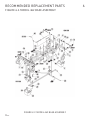
1
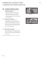
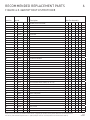
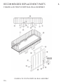
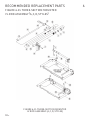
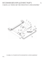
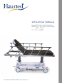
Operating Manual
Hausted® Horizon Series Stretchers
Model: 462 – A, C, D, E, F, G and H Tops
EMP – Youth
V1 02.11 068499
HAUSTED® Patient Handling Systems, LLC
WARNING - COPYING PROHIBITED
This manual is protected by Federal Copyright Law, which
provides for damages of up to USD $20000, as well as
criminal fines and imprisonment, for unauthorized copying.
a word from Hausted
This manual contains important information on
proper use and maintenance of the Hausted®
Horizon Stretcher. All personnel involved in the use
and maintenance of this equipment must carefully
review and comply with the warnings, cautions
and instructions contained in this manual. These
instructions are important to protect the health and
safety of personnel operating a Hausted Horizon
Stretcher and should be retained in a conveniently
accessible area for quick reference.
Complete instructions for uncrating have been
furnished. If missing, contact Hausted for replacement
copies, giving the serial number and model numbers
of the unit.
Hausted carries a complete line of accessories for use
with this stretcher. A Hausted representative will gladly
review these with you.
Indications for Use
on a scheduled basis to assure equipment performance
at peak capability and to help avoid untimely or costly
interruptions. Hausted maintains a global staff of well
equipped, factory-trained technicians to provide this
service, as well as expert repair services. Please contact
your Hausted representative for details.
Advisory
A listing of the safety precautions to be observed
when operating and servicing this equipment can be
found in Section 1 of this manual. Do not operate or
service the equipment until you have become familiar
with this information.
Any alteration of this equipment not authorized or
performed by Hausted Engineering Service which
could affect its operation will void the warranty,
could adversely affect use of this equipment, could
violate national, state, and local regulations, and could
jeopardize your insurance coverage.
The Hausted Horizon Series Multi-Purpose Stretchers and Youth Care Stretchers are designed for patient
transport, treatment and recovery.
Service Information
A thorough preventive maintenance program is
essential to safe and proper unit operation. This
manual contains maintenance schedules and
procedures which should be followed for satisfactory
equipment performance.
You are encouraged to contact Hausted concerning our
comprehensive Annual Maintenance Agreements. Under
the terms of these agreements, preventive maintenance,
adjustments, and replacement of worn parts are done
©2011 Hausted® Patient Handling Systems LLC. All Rights ReservedPrinted in U.S.A.
i
068499
EC Authorized Representative
CEpartner4U BV
ESDOORNLAAN 13
3951DB MAARN
The Netherlands
+31(0)6 516 536 26
Manufactured by:
Hausted® Patient Handling Systems, LLC
2511 Midpark Road
Montgomery, AL 36109
334.215.5151 Main
877.706.5151 Toll Free
334.215.5150 Fax
www.Hausted.com
Equipment not suitable for use in the presence
of a flammable anesthetic mixture with air or
oxygen or nitrous oxide.
The base language of this document is
ENGLISH. Any translations must be made
from the base language document.
ii
068499
Table of Contents
1 Listing of Warnings and Cautions................................................................................................................ 1-1
2 Uncrating Instructions........................................................................................................................................... 2-1
3 Operating Instructions.......................................................................................................................................... 3-1
3.1 Braking and Steering Operation..............................................................................................................................3-1
3.1.1 Applying The Brakes.................................................................................................................................................3-1
3.1.2 Releasing The Brakes...............................................................................................................................................3-1
3.1.3 Applying the Steering Lock/Fifth Wheel ..........................................................................................................3-2
3.1.4 Releasing the Steering Lock/Fifth Wheel ........................................................................................................3-2
3.2 Litter Top Height Adjustment ..................................................................................................................................3-3
3.2.1 Height Adjustment....................................................................................................................................................3-3
3.2.2 Lowering Litter Top...................................................................................................................................................3-3
3.2.3 Trendelenburg Adjustment.....................................................................................................................................3-3
3.2.4 Reverse Trendelenburg Adjustment....................................................................................................................3-3
3.3 Fowler Backrest Operation........................................................................................................................................3-4
3.3.1 Raising the Backrest.................................................................................................................................................3-4
3.3.2 Lowering the Backrest.............................................................................................................................................3-4
3.4 Backrest/Knee Flex Operation (Manual Models)................................................................................................3-5
3.4.1 Raising the Backrest/Knee Flex............................................................................................................................3-5
3.4.2 Lowering the Backrest/Knee Flex........................................................................................................................3-5
3.5 Air Glide Rail Operation..............................................................................................................................................3-6
3.5.1 Raising The Rail.........................................................................................................................................................3-6
3.5.2 Lowering The Rail......................................................................................................................................................3-6
3.5.3 Install Armboard Adaptor and Surgical Bar......................................................................................................3-7
3.6 Retracto Rail Operation...............................................................................................................................................3-8
3.6.1 Raising the Rail..........................................................................................................................................................3-8
3.6.2 Half Height...................................................................................................................................................................3-8
3.6.3 Lowering the Rail.......................................................................................................................................................3-8
3.7 Rail Operation (Youth Stretcher)..............................................................................................................................3-9
3.7.1 Raising the Rail to Full Height..............................................................................................................................3-9
3.7.2 Raising the Rail to Half Height.............................................................................................................................3-9
3.7.3 Lowering the Rail.......................................................................................................................................................3-9
3.8 Optional Pushbar Operation................................................................................................................................... 3-10
3.8.1 Deploying Pushbars............................................................................................................................................... 3-10
iii
068499
Table of Contents
3.8.2 Storing Pushbars..................................................................................................................................................... 3-10
4 Recommended Preventive Maintenance................................................................................................ 4-1
5 Recommended Optional Accessories. ....................................................................................................... 5-1
6Recommended Replacement Parts............................................................................................................. 6-1
7Warranty............................................................................................................................................................................ 7-1
iv
068499
Listing of Warnings and cautions
The following Safety Precautions must be observed
when operating or servicing Hausted® Horizon Series
Stretchers . WARNING indicates the potential for
personal injury and CAUTION indicates the potential
for damage to equipment. For emphasis, certain Safety
Precautions are repeated throughout the manual. It is
important to review ALL Safety Precautions before
operating or servicing the unit.
Strictly following these Safety Precautions enhances
your ability to safely and effectively utilize the unit
and helps the customer avoid improper maintenance
methods which may damage the unit or render it
unsafe. It is important to understand that these
Safety Precautions are not exhaustive; customers
are encouraged to develop their own safety policies
and procedures to enhance and compliment these
Safety Precautions.
WARNING–PERSONAL INJURY HAZARD
AND/OR EQUIPMENT DAMAGE HAZARD:
l
Repairs and adjustments to this equipment
should be made only by fully qualified
service personnel. Maintenance performed
by inexperienced, unqualified personnel or
installation of unauthorized parts could cause
personal injury, invalidate the warranty, or
result in costly equipment damage. Contact
Hausted regarding service options.
l
Do not sit on end – tipping may occur.
stretchers have a warning label located
lThe
near the head end stating: Maximum patient
weight 226 kg (500 lbs.). For Pediatric models
only, this label reads: Maximum patient weight
147 kg (325 lbs).
1-1
068499
1
entry, egress and transfer should always
lPatient
be done with caster braking system locked.
braking system should always be locked
lCaster
when patient is not in transport.
braking system should always be
lCaster
locked and patient side rails up when patient
is left unattended.
ensure that side rail is locked before
lAlways
leaving patient unattended.
WARNINGS – LACERATION HAZARD:
cutting bands always use a tool
lWhen
specifically designed for that purpose.
This will help to avoid personal injuries
frequently incurred when bands are cut and
tension released.
WARNINGS – PROPER OPERATION
HAZARD:
must be smooth and level to maintain
lFloors
optimum fifth wheel steering. Fifth wheel
steering functions can be influenced by floor
irregularities (bumps or dips) greater than
1/2" (13 mm) across the span of the stretcher.
UnCrating instructions
l
IMPORTANT - REPORT ANY
SHIPPING DAMAGE IMMEDIATELY:
Inform shipper of any damages - leave carton
intact. Leave the equipment in the receiving
area until inspection is complete.
- POSSIBLE EQUIPMENT
lCAUTION
DAMAGE:
This crate contains fragile expensive medical
equipment. Uncrate and handle carefully.
If after uncrating the equipment you find any
damage (no matter how slight), show it to
your supervisor.
- PERSONAL
lWARNING
INJURY HAZARD:
When cutting bands, always use tool specifically
designed for that purpose. This will help avoid
personal injuries frequently incurred when
bands are cut and tension is released.
2
IMPORTANT: Follow each step in the order shown
in these instructions.
UNPACKING INSTRUCTIONS:
Your Hausted equipment has been carefully packed
at our manufacturing plant to ensure safe shipment
to your medical facility. There are several procedures
you must follow to put your new equipment in service.
These procedures only take a few minutes to complete
and are required to ensure proper operation of the
equipment.
1. Cut the two bands around the shipping carton.
2. Remove the top half of the carton and cut one side
of the bottom half.
3. Remove the equipment from the carton.
4. Check to see if all features of the equipment work
properly. If all the features work, advance to step 5.
If any of the features of the equipment do not work
properly, call Hausted for service at: 877.706.5151.
5. Clean the equipment using mild detergent to remove
any dirt accumulated during shipment, and place the
equipment into service.
2-1
068499
operating instructions
3
3.1 Breaking and steering operation
l
WARNING–PERSONAL INJURY
HAZARD AND/OR EQUIPMENT
DAMAGE HAZARD:
• Caster braking system should always be
locked when patient is not in transport.
• Caster braking system should always be
locked and patient side rails up when patient
Figure 3-1
is left unattended.
3.1.1 Applying the Brakes
Four-wheel central braking system is
activated by depressing a red pedal at any of
the unit’s four corners (Figure 3-1). To fully
engage brakes, press pedal to approximately
45º. All four caster wheels should be locked
from swiveling and rotating.
3.1.2 Releasing the Brakes
Depress green pedal at any of the unit’s four
corners, until pedal is in a horizontal position
(Figure 3-2). All four wheels should rotate and
swivel freely.
NOTE: Brakes should always be activated when unit is not in transport.
3-1
068499
Figure 3-2
operating instructions
3
3.1 Breaking and steering operation
l
WARNING–PROPER OPERATION
HAZARD:
Floors must be smooth and level to maintain
optimum fifth wheel steering. Fifth wheel
steering functions can be influenced by floor
irregularities (bumps or dips) greater than
1/2" (13 mm) across the span of the stretcher.
Figure 3-3
3.1.3 Applying the Steering
Lock/Fifth Wheel
From any corner of stretcher, depress green
pedal downward into locked position. (Figure
3-3). Steering Lock – One caster at foot end
locks into a non-swivel mode, allowing straight
steering by the attendant. Fifth Wheel –
A center-steer caster lowers and applies
pressure to floor, allowing straight steering
by the attendant.
3.1.4 Releasing the Steering
Lock/Fifth Wheel
Depress red pedal at any of the unit’s four
corners, until pedal is in a horizontal position
(Figure 3-2). All four wheels should rotate and
swivel freely, and/or optional fifth wheel lifts
off floor.
3-2
068499
operating instructions
3
3.2 Litter top height adjustment
3.2.1 Height Adjustment
Press pump pedal to floor (Figure 3-4), then
release. Repeat this process until desired height
is obtained. Use smooth strokes on pump pedal
to ensure patient comfort.
3.2.2 Lowering Litter Top
Press down on two release pedals at the
same time (Figure 3-5) until desired height
is obtained.
Figure 3-4
NOTE: Do not stand on release pedals.
3.2.3 Trendelenburg Adjustment
Place unit at maximum height, see SECTION
3.2.1, HEIGHT ADJUSTMENT, PAGE 3-2. Press
down on the release pedal nearest the head end
(Figure 3-6) until desired position is obtained
then remove pressure.
Figure 3-5
3.2.4 Reverse Trendelenburg Adjustment
Place the unit at maximum height, see SECTION
3.2.1, HEIGHT ADJUSTMENT, PAGE 3-2.
Press down on release pedal nearest foot end
(Figure 3-7) until desired position is obtained
then remove pressure.
Figure 3-6
Figure 3-7
3-3
068499
operating instructions
3
3.3 Fowler backrest operation
3.3.1 Raising the Backrest
Grasp fowler backrest frame tube and gas spring
activating handle from either side of stretcher.
Squeeze handle and tube together and lift.
Once desired incline is achieved, release handle.
NOTE: The amount of manual lifting required will vary depending on patient
size, gas spring is intended only to assist in lifting patient.
Figure 3-4
3.3.2 Lowering the Backrest
Grasp fowler backrest frame tube and gas
spring activating handle from either side of the
stretcher. See Figure 3-8. Squeeze handle and
tube together while supporting fowler. Adjust
incline either by slowly lowering patient or by
pressing fowler down. Release handle once
desired incline is achieved.
NOTE: The amount of manual supporting required will vary depending on
patient size, the gas spring is intended only to assist in lowering patient.
3-4
068499
operating instructions
3.4 backrest/knee flex operation (Manual models)
3.4.1Raising the Backrest/Knee Flex
To elevate backrest or knee flex, flip crank
handle upwards, and rotate crank handle
clockwise. See Figure 3-9. When reaching
desired position, stop rotating handle and
return crank handle to its original position.
See Figure 3-10.
3.4.2 Lowering the Backrest/Knee Flex
Figure 3-9
To lower backrest or knee flex, flip crank
handle upwards, and rotate crank handle
counterclockwise, See Figure 3-9. When
reaching desired position, stop rotating
handle and return crank handle to its original
position. See Figure 3-10.
Figure 3-10
3-5
068499
3
operating instructions
3
3.5 airglide rail operation
3.5.1 Raising the Rail
Refer to Figures 3-11A & 3-11B. Grasp rail
top tube from under litter top firmly. Then
pull up until rail locks into full up position.
NOTE: Verify latching of rail before leaving patient unattended.
3.5.2 Lowering the Rail
Firmly grasp top of rail, pull out on red tab
located under litter top at foot or head end
(Figure 3-12). Lower side rail completely under
litter top.
Figure 3-11A
Figure 3-11B
Figure 3-12
3-6
068499
operating instructions
3
3.5 Airglide rail operation
3.5.3 Install Armboard Adaptor
and Surgical Bar
1. Refer to Figure 3-13. Install surgical bar
adaptor by positioning adapter over bumper
channel and pad. Then slide adapter
downward until it rests on channel.
2. Refer to Figure 3-14. Secure adapter by
inserting tethered pin into hole in adaptor.
Insert fully until pin is locked through both
sides of the adapter.
3. Refer to Figures 3-15A and 3-15B. Mount
armboard to adaptor by tilting armboard
upwards slightly, engaging upper portion
of clamp over surgical bar on adaptor.
a. Once armboard is engaged with surgical
bar, lower to horizontal position to lock.
b. To remove Armboard, depress gravity latch
and lift armboard from surgical bar.
Figure 3-13
Figure 3-14
Figure 3-15A
Figure 3-15B
3-7
068499
operating instructions
3
3.6 Retracto rail operation
l
WARNING–PROPER OPERATION
HAZARD:
• Patient entry, egress and transfer should
always be done with caster braking
system locked.
• Caster braking system should always be
locked and patient side rails up when patient
is left unattended.
Figure 3-16
3.6.1 Raising the Rail
Grasp rail top cap in the middle of the rail
(Figure 3-16), and lift.
3.6.2 Half Height
Grasp the rail (Figure 3-16); lift up on red
trigger under the litter top (Figure 3-17) while
lowering rail. When rail starts to move down
release trigger. Lower rail until it locks into
half height position.
Figure 3-17
3.6.3 Lowering the Rail
Grasp the rail (Figure 3-16), lift up on the red
trigger under the top (Figure 3-17) while
lowering the rail. Hold up on the trigger
until the rail is all the way down.
NOTE: Be sure both rails are in upright locked position before
leaving patient.
3-8
068499
operating instructions
3
3.7 Rail Operation (Youth Stretcher)
l
WARNING–PROPER OPERATION
HAZARD:
• Patient entry, egress and transfer should
always be done with caster braking
system locked.
• Caster braking system should always be
locked and patient side rails up when patient
is left unattended.
3.7.1 Raising the Rail to Full Height
Refer to Figure 3-18A & 3-18B. Grasp the rail
top tube in the center of the rail with free hand
squeeze the rail trigger. Lift the rail all the way
up. Once the rail is all the way up, release the
rail trigger and lower the rail slowly until the
trigger engages. Check rail lock by trying to
squeeze the rail trigger, if you cannot squeeze
the trigger the rail is locked securely, release
the rail top tube.
Figure 3-18A
Figure 3-18B
NOTE: Be sure rail is locked securely before leaving patient.
NOTE: Never leave the patient unattended with the rail down.
3.7.2 Raising the Rail to Half Height
Refer to Figure 3-18B. Grasp rail top tube in
center of rail and raise rail until it engages.
Check rail lock by trying to squeeze rail trigger. If trigger will not squeeze, the rail is locked
securely. Release rail top tube.
NOTE: Be sure rail is locked securely before leaving patient.
3.7.3 Lowering the Rail
Refer to Figure 3-18C. Grasp top tube in center
of rail and squeeze rail trigger with free hand
while lifting slightly on rail. This should allow
rail trigger to release trigger lock. Lower rail
slowly. If ‘half height’ is desired, release rail
trigger as soon as the rail starts lowering. If ‘full
down’ is desired continue to squeeze the trigger
until rail is completely lowered.
NOTE: Be sure rail is locked securely before leaving patient.
3-9
068499
Figure 3-18C
operating instructions
3
3.8 Optional pushbar operation
NOTE: Refer to PUSH HANDLE R.R. UNITS ASSEMBLY, 075656-00 for
installation procedure, if necessary.
3.8.1Deploying Pushbars
Refer to Figure 3-19. Grasp handles at the rear
of litter top and rotate them 90° upward until
fully deployed for use.
3.8.2 Storing Pushbars
Refer to Figure 3-19. Rotate lock knobs counterclockwise until each stops turning. Then rotate
handles 90° until level with stretcher top.
Rotate pushbars 90°
to deploy or store
Lock Knob
Figure 3-19
3-10
068499
Recommended preventive maintenance
l
4
AUTION – POSSIBLE EQUIPMENT
C
DAMAGE HAZARD
Steam cleaning and pressure washing
of stretcher is not recommended and can
void warranty.
Procedure
Schedule
Material
Lubricate all moving and sliding
parts and hinge points
3 Months
Inspect all fasteners to ensure
proper fit, position and tightness
(including nuts, bolts, etc.).
3 Months
Lubricating oil, light-duty grease,
wax stick lubricant or graphite
Lubricant.
Proper size wrench and screwdriver.
Wipe mattresses and pads with
damp cloth to remove any foreign
materials
After each use
Routine Hospital Grade disinfectants,
soap and water. Use only medium
strength cleaners. (DO NOT pressure
clean or steam clean.)
Inspect all surfaces and remove
any user developed sharp or
burred areas. Apply touch-up
where required.
Clean external surface to
remove blood, dirt, lint and any
other deposits
3 Months
Metal File, proper color paint
(specify color when ordering).
After each use
Medium strength anti-bacterial
cleaners, stainless steel cleaner
and polish. NOTE: If units are pressure washed or steam cleaned, lubrication of all hinging, moving, and sliding points should be done afterwards. (Pressure washing and
steam cleaning are not recommended procedures and can void warranty.)
For more detailed information, please contact:
Hausted Patient Handling Systems at
877.706.5151
4-1
068499
Recommended Optional accessories
I.V. Poles
AirGlide Rail Style Tops
066725
Mounted Stainless Steel Telescoping In. Rod
Retracto Rail Style Tops
00E17-00
Stainless Steel 42” Long I.V. Rod
066000
Telescoping I.V. Rod Mtd. At Head End W/Bumper – E & G Tops
066021
Telescoping I.V. Rod Mtd. At Head End W/Bumper – F & H Tops
Universal
000018
Stainless Steel 27” To 54” Long Telescoping I.V. Rod
126740-00
Infusion Pump In. Rod 1-1/8” Dia - 42” Long - Removable
IVSTOW-00
Mobile I.V. Stand Attachment
Pads and Mattresses
AirGlide Rail Style Tops
067167-60
2” x 28” x 76” Conductive Foam – “A” Rails
067177-60
3” x 28” x 76” Conductive Foam – “A” Rails
067178-60
Pressurecare – 4” x 28” x 76” Conductive Foam -“A” Rails
068923-60
Enhanced Pressurecare – 5” x 28” x 76” – “A” Rails
068020-60
3” x 28” x 76” Conductive Foam – “B” Rails
068021-60
Pressurecare – 4” x 28” x 76” Conductive Foam – “B” Rails
068924-60
Enhanced Pressurecare – 5” x 28” x 76” – “B” Rails
Retracto Rail Style Tops
031654-60
2” x 24-1/2” x 76” Conductive Foam – E & G Tops
031655-60
3” x 24-1/2” x 76” Conductive Foam – E & G Tops
061893-60
Pressurecare – 4” x 24-1/2” x 76” Cond. Foam – E & G Tops
068921-60
Enhanced Pressurecare – 5” x 24-1/2” x 76” – E & G Tops
031661
3” x 29-1/2” x 76” Conductive Foam – F & H Tops
061894-60
Pressurecare – 4” x 29-1/2” x 76” Cond. Foam – F & H Tops
068922-60
Enhanced Pressurecare – 5” X 29-1/2” X 76” – F & H Tops
Head and Foot Boards
AirGlide Rail Style Tops
067225-00
Head/Foot Board With Chart Holder
067221-00
Extension Head/Foot Board – With 1” Pad – With Chart Holder
Retracto Rail Style Tops
00CR6B-00
End Board With Chart Rack – E & G Tops
00CR7B-00
Extension Head/Foot Board – With Chart Rack – E & G Tops
0CRW6B-00
End Board With Chart Rack – F & H Tops
0CRW7B-00
Extension Head/Foot Board – With Chart Rack – F & H Tops
Monitor Shelves
AirGlide Rail Style Tops
068835-00
Extension Footboard/Monitor Shelf With Chart Holder
Retracto Rail Style Tops
000N45-00
5-1
068499
Monitor Shelf – Removable – Folding – E & G Tops
5
Recommended Optional accessories
068836-00
Extension Footboard/Mon. Shelf With Chart Rack – E & G Tops
00WN45-00
Monitor Shelf – Removable – Folding – F & H
068846-00
Extension Footboard/Mon. Shelf With Chart Rack – F & H Tops
5
X-Ray Accessories
AirGlide Rail Style Tops
00L25C-00
X-Ray Sub Top, “A” Tops Only
000027-00
X-Ray Cassette Holder With Handle, S.S.
Retracto Rail Style Tops
000054-00
Lateral X-Ray Cassette Holder – Holds Up To 14” X 17”
Miscellaneous
AirGlide Rail Style Tops
075664-00
Self-Storing Push-bars, Standard Width
075665-00
Self-Storing Handles, Extra Wide
065180-00
Armboard – Height Adjustable – 1” Pad Included
00C16H-00
Heel Stirrups
00C16L-00
Knee Crutch Stirrups
00L16M-00
Mounting Adaptor Clamps For Heel Stirrups Leg Holders
067741-00
Side Rail Pads
Retracto Rail Style Tops
00N16A-00
Heel Stirrups with Mounting Adaptors
00N16C-00
Knee Crutches with Mounting Adaptor
00N16E-00
Knee Crutches and Heel Stirrups with Mounting Adaptors
069257-00
Paper Roll Holder
076334-00
Armboard Stainless Steel with 2” Pad and Mounting Adaptor
128840-00
Drainage Bag Hooks
075656-00
Self Storing Push Bars
131934-00
Burgundy Bumpers and Labels For Department Identification
131935-00
Teal Bumpers and Labels For Department Identification
131936-00
Plum Bumpers and Labels For Department Identification
Universal
000012-00
Restraint Straps With Buckle
APC012-00
Restraint Straps With Velcro
128450-00
Vertical Oxygen Tank Holder
065366-00
Universal Patient Tray
Base Accessories
462 (Side Control)
068577-00
Burgundy Label Kit
068578-00
Teal Label Kit
Universal
075796
Center Track Steering – Model 462
recommended that only Hausted approved accessories be used with this device.
lItToisorder
accessories, or for more detailed information on accessories, please contact Hausted at:
1.877.706.5151
5-2
068499
replacement parts
6
Significant assemblies and components of the Hausted® Horizon Series Stretchers are illustrated and identified in
this section. The part number, the description and the quantity required for each usage are given. Each indentation in the description represents the assembly level. The UNITS PER ASSEMBLY column is specific for the given
assembly or subassembly level.
6.1 How to use the illustrated parts breakdown
1. Determine the function and application of the part required. Select the most appropriate title from the List of
Illustrations in the Table of Contents. Note the illustration page number.
2. Turn to the page indicated and locate the desired part on the illustration.
3. From the illustration, obtain the item number assigned to the desired part. Refer to the accompanying tabular
list (usually on the facing page) for the part number and description of the part.
Item No.
No indentation –Part of top assembly
Part No.
Description
P
146655
023
Arm and Lighthead Assembly
1
P
136807
181
CAP
2
P
136807
981
Funnel Cone Assembly
P
136807
979
• CAP, Shield
P
129362
378
• CLIP, Locking
P
93911
304
• CONE, Cap
P
136807
980
• FUNNEL, Cap
3
P
83628
001
SCREW, Button Head, #6-32 x 3/8 I
4
P
19684
061
LOCKWASHER, Helical, #6
5
P
90713
061
LOCKWASHER, Helical, #4
6
P
47760
091
SCREW, Button Head, #4-40 x
One Indentation – First subassembly, part
of assembly under which it is indented
6-1
068499
S
V
C
Recommended replacement parts
6
6.2 LIst of Illustrations
Figure 6-1. Model 462 Base Assembly...................................................................................................................................................6-3
Figure 6-2. Model 462 Base Assembly...................................................................................................................................................6-5
Figure 6-3. Top Assembly - Straight (A Style) (Part 1 of 3).............................................................................................................6-7
Figure 6-3. Top Assembly - KneeFlex (C Style) (Part 2 of 3)..........................................................................................................6-9
Figure 6-3. Top Assembly - KneeFlex (D - Extra Wide) (Part 3 of 3)........................................................................................ 6-11
Figure 6-4. Pneumatic (P Style) - A, C, and D Style......................................................................................................................... 6-13
Figure 6-5. Straight (A Style) Rail Assembly...................................................................................................................................... 6-15
Figure 6-6. Straight - Top Assemblies................................................................................................................................................. 6-17
Figure 6-7. KneeFlex - Top Assemblies (Part 1 of 2)...................................................................................................................... 6-19
Figure 6-7. KneeFlex - Top Assemblies (Part 2 of 2)...................................................................................................................... 6-21
Figure 6-8. Pneumatic (M Style)............................................................................................................................................................. 6-23
Figure 6-9. 462EMP Youth Stretcher.................................................................................................................................................... 6-25
Figure 6-10. Youth Vertical Rail Assembly......................................................................................................................................... 6-27
Figure 6-11. Three-Section Mounted I.V. Rod Assembly (A, C, D, Styles)................................................................................ 6-29
Figure 6-12. Three-Section Mounted I.V. Rod Assembly............................................................................................................... 6-31
Figure 6-13. 462 Fifth Wheel Center Track Assembly (Part 1 of 3)........................................................................................... 6-33
Figure 6-13. 462 Fifth Wheel Center Track Assembly (Part 2 of 3).......................................................................................... 6-35
Figure 6-13. 462 Fifth Wheel Center Track Assembly (Part 3 of 3)........................................................................................... 6-37
6-2
068499
Recommended replacement parts
Figure 6-1. Model 462 Base Assembly
Figure 6-2. Model 462 Base Assembly
6-3
068499
6
Recommended replacement parts
6
Figure 6-1. Model 462 Base Assembly
Item No.
S
V
C Description
Part No.
MODEL 462 BASE ASSEMBLY - NO 5TH WHEEL
Units Per Assembly
X
MODEL 462 BASE ASSEMBLY - WITH 5TH WHEEL
X
1
P
150830
492
BASE FRAME ASSEMBLY
1
1
2
P
056397
897
CASTER, BRAKE TOTAL LOCK
3
4
3
P
056397
896
CASTER, STEER LOCK
1
–
COVER, HORIZON BOTTOM, HEAD END
1
1
4
5
069281
HEX HEAD CAP SCREW, M8 x 1.25 x 16
8
8
6
P
065041
EYE BOLT, 5/16-18
4
4
7
031058
NUT, FREE THREAD 5/16
4
4
CAP SCREW WITH MYLAR PATCH
4
4
LOCK NUT, 5/16-18
4
4
8
9
150830
554
031101
P
150830
756
10
062684
CAM LEVER
2
4
11
068551
HORIZON BRAKE ROD
2
2
12
066507
LEFT, BRAKE PEDAL ASSEMBLY
2
2
13
066508
RIGHT, BRAKE PEDAL ASSEMBLY
2
2
14
069478
JACK MOUNTING PLATE
4
4
15
068338
COLLAR
4
4
16
068207
HYDRAULIC JACK, HEAD END
1
1
17
068209
HYDRAULIC JACK, FOOT END
1
1
18
035122
HEX HEAD CAP SCREW, 1/4-20 x 1 5/8
4
4
19
031337
HEX HEAD CAP SCREW, 1/4-20 x 3/4
4
4
20
031076
WASHER, FLAT1/4
18
18
21
031055
LOCK NUT, 1/4-20
13
13
22
031092
LOCK WASHER, 5/16 INTERNAL TOOTH
8
8
23
075241
JACK LINK ASSEMBLY
1
1
24
069280
COVER, HORIZON BOTTOM, FOOT END
1
1
25
068512
VELCRO PILE, 2 x 5/8
8
8
PUMP PEDAL ASSEMBLY
1
1
26
P
150830
599
27
068126
NYLINER, 1/2
2
2
28
068379
PUMP PEDAL HINGE BAR
1
1
29
075249
TEFLON TAPE, 2.5 x .75 (NOT SHOWN)
1
1
30
068355
VERTICAL GUIDE ANGLE
1
1
31
068417
RUE CLIP, 5/16
1
1
32
068418
NYLINER, 1/4
2
2
33
031006
HEX HEAD CAP SCREW, 1/4-20 x 1 1/2
1
1
34
031321
HEX HEAD CAP SCREW, 1/4-20 x 2
8
8
35
068380
TEFLON TAPE, 1.5 x .75
4
4
36
069492
STOP BUMPER
1
1
RELEASE ASSEMBLY, FOOT
1
1
BRACKET, AXLE BEARING
2
2
SELF TAPPING SCREW, #10-16 x .375 TYPE B
1
1
37
P
38
39
150830
747
069481
P
048064
045
6-4
068499
Recommended replacement parts
6
Figure 6-1. Model 462 Base Assembly
Item No.
Part No.
S
V
C Description
40
P
*
69484
Units Per Assembly
RELEASE PEDAL
2
2
41
031100
NYLON WASHER
1
1
42
068890
HEX HEAD CAP SCREW, #10-32 x 1/2
2
2
PUSH PLATE
2
2
1/4” STOP COLLAR
2
2
NYLON SHOULDER WASHER
2
2
43
44
068377
P
45
741
068530
46
47
150830
P
150830
746
RELEASE ASSEMBLY, HEAD
1
1
150830
742
SETSCREW, #10-32
2
2
NOTE: The P prefix on the part numbers marked with an *, designate part numbers for the powder coated units. For chrome/stainless units the
P prefix should be replaced with a 0 prefix.
6-5
068499
Recommended replacement parts
Figure 6-1. Model 462 Base Assembly
Figure 6-2. Model 462 Base Assembly
6-7
068499
6
Recommended replacement parts
6
Figure 6-1. Model 462 Base Assembly
Item No.
S
V
C Description
Part No.
MODEL 462 BASE ASSEMBLY - NO 5TH WHEEL
Units Per Assembly
X
MODEL 462 BASE ASSEMBLY - WITH 5TH WHEEL
X
1
075796
5th Wheel Sub-Assembly
–
1
2
031055
LOCKNUT, 1/4-20
–
4
3
031006
SCREW, Hex Head Cap, 1/4-20 x 1-1/2
–
4
4
031076
WASHER, Flat, 1/4
–
4
5
LOCKNUT, 5/16
–
2
6
062684
CAM
–
2
7
065807
BOLT, Shoulder, 3/8 x 3/8
–
2
8
068583
PLATE, Bellows Attachment
2
2
9
068550
BELLOWS
2
2
10
068208
COVER, Horizon Base Top
1
1
11
068512
PILE, Velcro, 2 x 5/8
8
8
12
068513
HOOK, VELCRO, 2 X 5/8
8
8
LINKAGE, Brake/Steer
1
1
13
P
P
150830
056397
756
930
14
065807
BOLT, Shoulder, 3/8 x 3/8
2
2
15
031156
GROMMET
4
4
6-8
068499
Recommended replacement parts
6
Figure 6-3. Top assembly – Straight (A Style ) (Part 1 of 3)
Figure 6-3. Top assembly – Straight (A Style) (Part 1 of 3)
6-9
068499
Recommended replacement parts
6
Figure 6-3. Top assembly – Kneeflex (C style ) (Part 2 of 3)
Figure 6-3. Top assembly – Kneeflex (C style) (Part 2 of 3)
6-10
068499
Recommended replacement parts
6
Figure 6-3. Top assembly – kneeflex (D Extra-Wide) (3 of 3)
Figure 6-3. Top assembly – kneeflex (D Extra-Wide) (3 of 3)
6-11
068499
Recommended replacement parts
6
Figure 6-1. Model 462 Base Assembly
Item No.
Part No.
S
V
C Description
TOP ASSEMBLY - STRAIGHT (A STYLE) REG. WIDTH
Units Per Assembly
X
TOP ASSEMBLY - KNEEFLEX (C STYLE) REG. WIDTH
X
TOP ASSEMBLY - KNEEFLEX (D STYLE) EXTRA WIDE
1
2
X
P67103
*
TOP WELDMENT, HEAD
1
1
–
P69221
*
TOP WELDMENT, HEAD - WIDE
–
–
1
P67104
*
TOP WELDMENT, FOOT
1
–
–
P67109
*
TOP WELDMENT, FOOT, KNEE FLEX
–
1
–
P69225
*
TOP WELDMENT, FOOT, KNEE FLEX - WIDE
–
–
1
TUBE PROTECTOR, EXTRUSION
2
2
2
3
075233
4
P67130
*
TOP SHEET
1
–
–
P67126
*
SEAT COVER SHEET
–
1
–
P69234
*
SEAT COVERSHEET, WIDE
–
–
1
5
066696
FOWLER HINGE TUBE
2
2
2
6
P68529
*
COVER, UNDER FOWLER
1
–
1–
P69247
*
COVER, UNDER FOWLER, WIDE
–
–
1
7
031012
HEX HEAD CAP SCREW, 5/16-18 X 1
4
4
4
8
031057
LOCK NUT, 5/16-18
14
20
20
9
031010
HEX HEAD CAP SCREW, 5/16-18 X 3/4
10
16
16
10
P68931
*
FOWLER ASSY. AIRGLIDE TOP
1–
1
–
P69441
*
11
031421
12
P67129
P69237
*
FOWLER COVER SHEET, WIDE
–
–
1
13
P67128
*
FOOT COVER SHEET
–
1
–
P69236
*
FOOT COVER SHEET, WIDE
–
–
1
P67127
*
KNEE COVER SHEET
–
1
–
P69235
*
KNEE COVER SHEET, WIDE
–
–
1
15
P67069
*
KNEE FLEX ASSY
–
1
–
P69250
*
KNEE FLEX ASSY., WIDE
–
–
1
16
031212
VELCRO HOOK, 2 x 12
2
2
2
17
065258
LOCKING COTTER PIN, RUE CLIP
1
1
1
14
*
FOWLER ASSY. AIRGLIDE TOP, WIDE
–
–
1
LOCK NUT, #10-24
–
2
2
FOWLER COVER SHEET
1–
1
–
18
031080
WASHER, 5/16
12
14
14
19
000794
POP RIVET, LARGE 3/16 x .45
29
34
34
20
067131
RAIL LATCH ASSY
2
2
2
21
075627
PIN, GAS SPRING HINGE
1
1
1
22
031055
LOCK NUT, 1/4-20
16
16
16
23
066540
CORNER BUMPER
4
4
4
24
075503
MACHINE SCREW, #10-24 x 1 3/8, PHILLIPS PAN HEAD
–
2
2
25
066613
RAIL LATCH CAP
4
4
4
26
068786
HEX HEAD CAP SCREW, 1/4-20 x 5/8
16
16
16
27
066603
LATCH SPRING
2
2
2
6-12
068499
Recommended replacement parts
6
Figure 6-3. Top assembly – Straight (A Style)
& Kneeflex (C & D Styles)
Item No.
Part No.
S
V
C Description
Units Per Assembly
28
068484
RIGHT, TOP ANGLE ASSY.
1
1
1
29
068483
LEFT, TOP ANGLE ASSY.
1
1
1
30
068495
GAS SPRING ANCHOR
1
1
–
069245
GAS SPRING ANCHOR
–
–
1
31
030432
CROSS BAR SHAFT
–
2
2
32
067136
LATCH TUBE SUPPORT
8
8
8
33
066605
LATCH TUBE SUPPORT PLATE
4
4
4
34
061375
WASHER, NYLON
6
6
6
35
031314
SPRING PIN, 3/16 x 3/4
4
6
6
36
069296
CRANK ANCHOR PLATE ASSY.
–
1
1
37
075235
TUBE PROTECTOR
2
2
–
075236
TUBE PROTECTOR, WIDE
–
–
2
38
065059
RATCHET PLATE
–
2
2
39
067143
STOP ANGLE
–
1
1
40
P67112
*
KNEE FLEX ASSEMBLY
–
1
–
P69226
*
41
031312
42
P67114
P69232
KNEE FLEX ASSEMBLY, WIDE
–
–
1
PIN, Spring, .250 x .750
–
2
2
*
ASSEMBLY, Foot Frame
–
1
–
*
ASSEMBLY, Foot Frame, Wide
–
–
1
43
066688
CAP, Vinyl
2
2
–
44
067113
SUPPORT, Knee Flex Foot
–
1
–
069229
SUPPORT, Knee Flex Foot, Wide
–
–
1
45
035115
WASHER, Nylon, .75 OD x .3915 ID
–
2
2
46
067149
SPACER, Foot Frame
–
2
2
47
031357
SCREW, Phillips Head Machine, .250-20 x 1.750
–
2
2
NOTE: The P prefix on the part numbers marked with an *, designate part numbers for the powder coated units. For chrome/stainless units the
P prefix should be replaced with a 0 prefix.
6-13
068499
Recommended replacement parts
figure 6-4. pneumatic ( p style ) - a, c, and d style
figure 6-4. pneumatic ( p style) - a, c, and d style
6-15
068499
6
Recommended replacement parts
6
figure 6-4. pneumatic ( p style ) - a, c, and d style
Item No.
Part No.
S
V
C Description
PNEUMATIC (P STYLE) - A & C STYLE (REG. WIDTH)
Units Per Assembly
X
PNEUMATIC (P STYLE) - D STYLE (X-WIDE)
1
X
P68442
*
FOWLER FRAME ASSEMBLY
1
–
P69241
*
FOWLER FRAME ASSEMBLY, WIDE
–
1
2
068441
ACTUATING PIN
1
1
3
066530
FOWLER HANDLE
2
2
4
066547
PIN, HANDE - HINGE
2
2
5
066548
CLEVIS PIN, .188 x .938
4
4
6
068438
PIVOT BALL
1
1
7
068436
BALL RETAINER
1
1
8
068437
GAS SPRING NUT
1
1
9
075403
STOP COLLAR
1
1
10
067287
GAS SPRING
1
1
11
075503
MACHINE SCREW, PHILLIPS PAN HEAD, #10-24 x 1 3/8
2
2
12
031421
LOCK NUT, #10-24
2
2
13
075410
SET SCREW, M5 x 10
1
1
14
068435
RELEASE ROD
2
–
069240
RELEASE ROD, WIDE
–
2
15
062654
LABEL, FOWLER
2
2
16
P67129
*
FOWLER COVER SHEET
1
–
P69237
*
FOWLER COVER SHEET, WIDE
–
1
17
000794
POP RIVET, LARGE 3/16 x .45
8
8
18
031212
VELCRO HOOK, 2 x 12
1
1
NOTE: The “P” prefix on the part numbers marked with an *, designate part numbers for the powder coated units. For chrome/stainless units the “P” prefix
should be replaced with a “0” prefix. (Example: Item 1 for a chrome/stainless unit would become 068442.)
6-16
068499
Recommended replacement parts
figure 6-5. straight ( A Style ) Rail assembly
This style rail is used on the
A, C, and D style tops only
figure 6-5. straight ( A Style) Rail assembly
6-17
068499
6
Recommended replacement parts
figure 6-5. straight ( A Style ) Rail assembly
Item No.
S
V
C Description
Part No.
STRAIGHT (A STYLE) RAIL ASSEMBLY
(this style rail is used on the A, C, & D style tops only)
1
Units Per Assembly
X
462 DPA
2
069238
CROSSTUBE, HEAD END, WELDMENT
1
3
068464
STOP COLLAR, 3/4 I.D.
6
4
068493
HORIZON TOP RETAINING PLUG
2
5
068521
AIRGLIDE RAIL ASSEMBLY
2
6
075530
• WELDMENT, RAIL TALL AIRGLIDE
7
066619
• NYLON WASHER
8
066616
• SHOULDER BOLT, 1/2 x 1-1/2
4
9
075532
• LOWER LINK LEFT, TALL RAIL
1
10
075535
• UPPER LINK LEFT, TALL RAIL
1
11
075536
• UPPER LINK RIGHT, TALL RAIL
1
12
075533
• LOWER LINK RIGHT, TALL RAIL
1
13
031021
ROUND HEAD SCREW, 1/4-20 x 1/4
2
14
062037
SHOULDER BOLT, 1/2 x 2
8
15
066619
NYLON WASHER, 3/4 OD x .505 ID
16
16
066618
LOCK NUT, 3/8-16
8
17
067712
BALL STUD, SHORT
4
18
067711
BALL STUD, LONG
4
19
031057
LOCK NUT, 5/16-18
8
20
075529
RAIL, GAS SPRING, 154/110 NEWTONS
4
21
030919
SHOULDER BOLT, 3/8-16
1
22
030918
HEX NUT, 3/8-16
1
23
066983
TRIM LOCK
4
24
067062
KNEEFLEX CRANK ASSEMBLY
1
25
065257
CLEVIS PIN
1
26
065258
RUE CLIP
5
27
030923
LOCK WASHER
1
28
069248
CROSSTUBE, FOOT END, WELDMENT
1
29
068466
ROLLER BRACKET ASSEMBLY
2
PIN, CLEVIS, 3/8 x 6-5/8
2
30
6
P
150830
358
1
6-18
068499
Recommended replacement parts
figure 6-6. straight - top assemblies
figure 6-6. straight - top assemblies
6-19
068499
6
Recommended replacement parts
6
figure 6-6. straight - top assemblies
Item No.
S
V
C Description
Part No.
STRAIGHT - TOP ASSEMBLIES - STYLE E (REGULAR WIDTH)
Units Per Assembly
X
STRAIGHT - TOP ASSEMBLIES - STYLE F (EXTRA-WIDE)
1
2
031118
X
SPRING PIN, 3/16 x 1
4
4
P
150830
489
HORIZON TOP WELDMENT
1
–
P
141210
510
HORIZON TOP WELDMENT, X-WIDE
–
1
RETAINING PLUG, HORIZON
2
2
3
068493
4
ROLLER BRACKET ASSEMBLY
2
2
5
P
150830
358
PIN, CLEVIS 3/8 x 6-5/8
2
2
6
P
150830
486
TOP COVER SHEET
1
–
P
150830
572
TOP COVER SHEET, X-WIDE (not shown in illustration)
–
2
7
075627
HINGE, GAS SPRING, PIN
1
1
8
031212
VELCRO, HOOK, 2 x 12
2
2
9
068464
COLLAR, 1.25 DIA x .765 ID
6
6
10
068469
CROSSTUBE, HEAD END
1
–
068471
CROSSTUBE, HEAD END, X-WIDE
–
1
068172
CROSSTUBE, FOOT END
1
–
068473
CROSSTUBE, FOOT END, X-WIDE
–
1
12
068466
ROLLER PIVOT BRACKET
2
2
13
065258
LOCKING COTTER PIN
5
5
14
031055
LOCKNUT, 1/4-20
19
19
15
031021
MACHINE SCREW, 1/4-20 x 1/4
2
2
16
068481
PLATE FOOT END
2
2
17
067958
CORNER BUMPER
4
4
18
067959
BUMPER, SIDE, GRAY
2
2
19
068154
BUMPER, END, GRAY
2
–
11
P69472
068151
BUMPER, END, GRAY, X-WIDE
–
2
20
031057
LOCKNUT, 5/16-18
12
12
21
062037
SHOULDER BOLT, 1/2 x 2
2
2
22
035138
SPACER
2
2
23
035137
ROCKER STOP
2
2
24
068917
ANCHOR, GAS SPRING
1
1
25
075226
I.V. WELL TOP CAP
4
4
26
075229
NYLON ARROW CLIP, 1/8
4
4
27
031010
HEX HEAD CAP SCREW, 5/16-18 x 3/4
12
12
28
066617
SHOULDER BOLT, 5/16 x 1-1/4
2
2
29
031004
HEX HEAD CAP SCREW, 1/4-20 x 1/2
2
2
30
068887
RETRACTO RAIL ASSEMBLY, RIGHT
1
1
31
068885
RETRACTO RAIL ASSEMBLY, LEFT
1
1
32
031455
WELD NUT, 1/4-20
8
8
33
035122
HEX HEAD CAP SCREW, 1/4-20 x 1-5/8
14
14
34
061195
BUTTON HEAD SOCKET SCREW, 1/4-20 x 5/8
8
8
6-20
068499
Recommended replacement parts
6
figure 6-6. straight - top assemblies
Item No.
S
V
C Description
Part No.
Units Per Assembly
35
069450
VINYL CAP ROLLER BRACKET
4
2
36
P65855
SHEET, FOWLER COVER
1
–
P65879
SHEET, FOWLER COVER, X-WIDE
–
1
37
000794
CHERRY RIVET, 3/16 x .45
20
20
38
P68929
*
FOWLER ASSEMBLY
1
–
P68930
*
FOWLER ASSEMBLY, X-WIDE
–
1
PLATE, SUPPORT RETRACTO RAIL
2
2
39
068198
NOTE: The “P” prefix on the part numbers marked with an *, designate part numbers for the powder coated units. For chrome/stainless units the “P” prefix
should be replaced with a “0” prefix.
6-21
068499
Recommended replacement parts
Figure 6-7. KneeFlex – Top Assemblies (1 of 2)
Figure 6-7. KneeFlex – Top Assemblies (1 of 2)
6-23
068499
6
Recommended replacement parts
Figure 6-7. KneeFlex – Top Assemblies (2 of 2)
6
Figure 6-7. KneeFlex – Top Assemblies (2 of 2)
6-24
068499
Recommended replacement parts
6
Figure 6-7. KneeFlex – Top Assemblies
Item No.
S
V
C Description
Part No.
KNEEFLEX - TOP ASSEMBLIES - STYLE G (REGULAR WIDTH)
Units Per Assembly
X
KNEEFLEX - TOP ASSEMBLIES - STYLE H (EXTRA-WIDE)
1
2
031118
SPRING PIN, 3/16 x 1
4
4
P
150830
489
HORIZON TOP WELDMENT
1
–
P
141210
510
HORIZON TOP WELDMENT, X-WIDE
–
1
RETAINING PLUG, HORIZON
2
2
ROLLER BRACKET ASSEMBLY
2
2
PIN, CLEVIS 3/8 x 6-5/8
2
2
P65250
KNEE FLEX CRANK SUPPORT, FOOT END
1
–
3
068493
4
5
X
P69472
P
6
150830
358
P65254
KNEE FLEX CRANK SUPPORT, FOOT END, X-WIDE
–
1
7
030918
HEX NUT, 3/8-16
1
1
8
075627
HINGE, GAS SPRING, PIN
1
1
9
031212
VELCRO, HOOK, 2 x 12
2
2
10
068464
COLLAR, 1.25 DIA x .765 ID
6
6
11
068469
CROSSTUBE, HEAD END
1
–
068471
CROSSTUBE, HEAD END, X-WIDE
–
1
068172
CROSSTUBE, FOOT END
1
–
068473
CROSSTUBE, FOOT END, X-WIDE
–
1
13
068466
ROLLER PIVOT BRACKET
2
2
14
031327
BUTTON HEAD SOCKET SCREW, 1/4-20 x 1
8
8
15
031055
LOCKNUT, 1/4-20
23
23
16
P68929
*
FOWLER ASSEMBLY
1
–
P68930
*
12
FOWLER ASSEMBLY, X-WIDE
–
1
17
067958
CORNER BUMPER
4
4
18
067959
BUMPER, SIDE, GRAY
2
2
19
068154
BUMPER, END, GRAY
2
–
068151
BUMPER, END, GRAY, X-WIDE
–
2
MOUNTING BLOCK, THIGH
2
2
20
P
150830
490
21
062037
SHOULDER BOLT, 1/2 x 2
2
2
22
075226
I.V. WELL TOP CAP
4
4
23
075229
NYLON ARROW CLIP, 1/8
4
4
24
068917
ANCHOR, GAS SPRING
1
–
P68912
ANCHOR, GAS SPRING, X-WIDE
–
1
P62226
FOOT SECTION COVER
1
–
P62261
FOOT SECTION COVER, X-WIDE
–
1
26
065258
LOCKING COTTER PIN
6
6
27
062358
ACCESSORY SUPPORT CHANNEL
1
–
062359
ACCESSORY SUPPORT CHANNEL, X-WIDE
–
1
28
031021
MACHINE SCREW, 1/4-20 x 1/4
2
2
29
P33013
LEG SECTION COVER
1
–
P33050
LEG SECTION COVER, X-WIDE
–
1
25
6-25
068499
Recommended replacement parts
6
Figure 6-7. KneeFlex – Top Assemblies
Item No.
S
V
C Description
Part No.
Units Per Assembly
30
068887
RETRACTO RAIL ASSEMBLY, RIGHT
1
1
31
068885
RETRACTO RAIL ASSEMBLY, LEFT
1
1
32
P
056397
890
KNEE FLEX ASSEMBLY
1
–
P
150830
540
KNEE FLEX ASSEMBLY, X-WIDE
–
1
33
35122
HEX HEAD CAP SCREW, 1/4-20 x 1-5/8
14
14
34
P65855
SHEET, FOWLER
1
–
P65879
SHEET, FOWLER, X-WIDE
–
1
35
069450
VINYL CAP ROLLER BRACKET
4
2
36
065061
KNEE-FLEX RATCHET PLATE ASSEMBLY, LEFT
1
1
37
031337
HEX HEAD CAP SCREW, 1/4-20 x 3/4
10
10
38
065060
KNEE-FLEX RATCHET PLATE ASSEMBLY, RIGHT
1
1
39
000794
CHERRY RIVET, 3/16 x .45
24
24
40
41
LOCKNUT, #10-24
1
1
P
031421
150830
626
COVER, Seat Section
1
–
P
150830
639
COVER, Seat Section, Wide
–
1
42
031455
NUT, Weld, 1/4-20
8
8
43
068198
PLATE, Support Retracto Rail
2
2
44
066617
BOLT, Shoulder, 5/16 x 1-1/4
2
2
45
031004
SCREW, Hex Head Cap Screw, 1/4-20 x 1/2
2
2
46
031010
SCREW, Hex Head Cap Screw, 5/16-18 x 3/4
16
16
47
031057
LOCKNUT, 5/16-18
12
12
48
035137
STOP, Rocker
2
2
49
030923
WASHER, Lock
1
1
50
068481
PLATE, Foot End
2
2
51
035138
SPACER
2
2
52
075502
SCREW, Phillips Head, #10-24 x 1-1/8
1
1
53
030919
BOLT, Special Shoulder, 1/2 x1-1/2
1
1
54
065257
PIN, CLEVIS
1
1
55
062209
SHAFT, Crossbar
2
2
56
031364
WASHER, Flat, 1/4
2
2
57
068724
ASSEMBLY, 462 Elevating Crank
1
1
58
061195
SCREW, Button Head Socket, 1/4-20 x 5/8
8
8
NOTE: The “P” prefix on the part numbers marked with an *, designate part numbers for the powder coated units. For chrome/stainless units the “P” prefix
should be replaced with a “0” prefix. (Example: Item 16 for a chrome/stainless unit would become 068929)
6-26
068499
Recommended replacement parts
figure 6-8. pneumatic ( M style )
figure 6-8. pneumatic (M style)
6-27
068499
6
Recommended replacement parts
6
figure 6-8. pneumatic ( M style )
Item No.
S
V
C Description
Part No.
PNEUMATIC (M STYLE) - E & G STYLE (REG. WIDTH)
Units Per Assembly
X
PNEUMATIC (M STYLE) - F & H STYLE (X-WIDE)
1
X
P68907
*
FOWLER FRAME ASSEMBLY, USED W/RETRACTO RAIL
1
–
P68901
*
FOWLER FRAME ASSEMBLY, WIDE,
USED W/RETRACTO RAIL
–
1
2
068441
ACTUATING PIN
1
1
3
075410
SET SCREW, M5 x 10
1
1
4
066530
FOWLER HANDLE
2
2
5
066547
PIN, HANDE - HINGE
2
2
6
066548
CLEVIS PIN, .188 x .938
4
4
7
067287
GAS SPRING
1
1
8
068436
BALL RETAINER
1
1
9
068438
PIVOT BALL
1
1
10
068435
RELEASE ROD, SHORT
1
–
069240
RELEASE ROD, SHORT, X-WIDE
–
1
068909
RELEASE ROD, LONG
1
–
11
069431
RELEASE ROD, LONG, X-WIDE
–
1
12
068437
GAS SPRING NUT
1
1
13
075403
STOP COLLAR
1
1
14
062654
LABEL, FOWLER
2
2
NOTE: The “P” prefix on the part numbers marked with an *, designate part numbers for the powder coated units. For chrome/stainless units the “P” prefix
should be replaced with a “0” prefix. (Example: Item 1 for a chrome/stainless unit would become 068907)
6-28
068499
Recommended replacement parts
figure 6-9. 462EmP youth Stretcher
figure 6-9. 462EmP youth Stretcher
6-29
068499
6
Recommended replacement parts
figure 6-9. 462EmP youth Stretcher
Item No.
S
V
C Description
Part No.
462EMP YOUTH STRETCHER
1
2
6
Units Per Assembly
X
BASE FINAL ASSEMBLY
P
3
150830
489
068493
4
P69472
*
TOP WELDMENT, REGULAR WIDTH
1
HORIZON TOP RETAINING PLUG
2
ROLLER BRACKET ASSEMBLY
2
5
P
150830
358
CLEVIS PIN
2
6
P
150830
486
TOP COVER SHEET
1
7
000794
CHERRY RIVET, 3/16 x .250”
22
8
031212
VELCRO HOOK, CORNERS
2
COLLAR, 1.25 DIA x .764 ID
6
SHEET, FOWLER COVER
1
ROLLER PIVOT BRACKET ASSEMBLY
2
9
068464
10
P65855
11
068466
*
12
065258
RUE CLIP
5
13
031055
LOCKNUT, 1/4-20
12
14
067958
BUMPER CHANNEL CORNER, 826
4
15
067959
BUMPER EXTRUSION, 826
2
16
068154
EXTRUSION CHANNEL
2
17
P68929
18
062037
*
FOWLER ASSEMBLY
1
SHOULDER BOLT, 1/2 x 2
2
19
075627
HINGE PIN, GAS SPRING
1
20
128930
SIDE RAIL ASSEMBLY
2
21
066250
END RAIL ASSEMBLY
2
22
031321
HEX HEAD CAP SCREW, 1/4-20 x 2
8
23
069450
VINYL CAP
4
24
013111
VERTICAL RAIL SPACER
8
25
000990
DOUBLE SIDED TAPE, 2” LONG
4
26
069066
MOUNTING PLATE, LABEL
2
27
061195
BUTTON HEAD SOCKET SCREW, 1/4-20 x 5/8”
8
28
031455
WELD NUT, 1/4-20
8
29
067292
BUTTON HEAD SOCKET SCREW, 5/16-18 x 3/4”
12
30
031057
LOCKNUT, 5/16-18
12
31
031021
MACHINE SCREW, 1/4-20x 1/4”
2
32
068469
CROSS TUBE, HEAD
1
33
068172
CROSS TUBE, FOOT
1
34
000787
WASHER
2
35
068917
ANCHOR ASSEMBLY, GAS SPRING
1
36
031118
SPRING PIN, 3/16 x 1”
4
37
075226
I.V. WELL TOP CAP
4
38
075229
CLIP, NYLON
4
39
068481
PLATE, FOOT END SUPPORT
2
40
062080
BROOM CLIP
2
NOTE: The “P” prefix on the part numbers marked with an *, designate part numbers for the powder coated units. For chrome/stainless
units the “P” prefix should be replaced with a “0” prefix. (Example: Item 4 for a chrome/stainless unit would become 069472.)
6-30
068499
Recommended replacement parts
figure 6-10. Youth vertical rail assembly
figure 6-10. Youth vertical rail assembly
6-31
068499
6
Recommended replacement parts
figure 6-10. Youth vertical rail assembly
Item No.
S
V
C Description
Part No.
1
128930
2
12893D
Units Per Assembly
YOUTH VERTICAL RAIL ASSEMBLY
X
SIDE RAIL ASSEMBLY
2
• LOWER RAIL
2
3
P
056397
933
• TUBE ASSEMBLY, LOCK, VERTICAL
1
4
P
056397
932
• VERTICAL TUBE
1
• UPPER RAIL END TUBE ASSEMBLY
10
• VERTICAL RAIL BRACE ASSEMBLY
1
• PEDIATRIC RAIL LOCKING TUBE
1
5
12893B
6
7
12893C
P
056397
939
8
069098
• VERTICAL RAIL SLIDE TUBE ASSEMBLY
1
9
031037
• PHILLIPS OVAL HEAD SCREW, 1/4-20 x 1 1/2
28
10
035419
• RAIL CUSHION HOSE
4
11
12893E
• RAIL CAP EXTRUSION, 68
1
12
069214
• RAIL PLUNGER, 5/16-18 x 5/8
1
13
068485
• DOUBLE SIDED TAPE, 2 LONG PIECE
3
• PHILLIPS OVAL HEAD SCREW, 1/4-20 x 1 1/4
4
• UPPER RAIL
1
14
P
150830
594
15
12893A
16
066250
17
066254
• HEAD & FOOT END FRAME ASSEMBLY
1
18
066252
• HEAD & FOOT END VERTICAL ROD TALL
5
19
031037
• PHILLIPS OVAL HEAD SCREW, 1/4-20 x 1 1/2
2
20
062343
• HEAD & FOOT END RAIL BASE TUBE
1
21
069083
• END RAIL CAP EXTRUSION
1
22
068475
• DOUBLE SIDED TAPE, 2 LONG PIECE
2
23
050233
• CHAIN, 12 ASSEMBLY
1
24
062377
• PIN & RING ASSEMBLY
1
HEAD & FOOT END RAIL ASSEMBLY
6
2
6-32
068499
Recommended replacement parts
Figure 6-11. Three - Section Mounted
I.V. Rod assembly ( A, C, D, Styles )
Figure 6-11. Three-Section Mounted
I.V. Rod assembly (A, C, D, Styles )
6-33
068499
6
Recommended replacement parts
Figure 6-11. Three - Section Mounted
I.V. Rod assembly ( A, C, D, Styles )
Item No.
Part No.
S
V
C Description
Units Per Assembly
THREE-SECTION MOUNTED I.V. ROD ASSEMBLY (A, C, D,
STYLES
X
I.V. ROD THREE-SECTION ASSEMBLY, SHORT
1
1
066726
2
066731
• SHORT OUTSIDE TUBE
1
3
069456
• SPRING PIN, 3/16 x 1 3/8
1
4
066014
• SQUEEZE BUSHING, LARGE
1
5
066013
• SCREW COLLAR, LARGE
1
6
066732
• SLIDE TUBE, SHORT
1
7
066015
• CAP GLIDE, OUTSIDE
1
8
031314
• SPRING PIN, 3/16 x 3/4
1
9
030209
• SQUEEZE BUSHING
1
10
030207
• SCREW COLLAR
1
11
066733
• INSIDE TUBE, SHORT
1
12
030176
• CAP GLIDE, INSIDE
1
13
065605
• SPRING PIN, 1/8 x 1/2
1
14
031110
• SPRING PIN, 3/16 x 7/8
1
15
061411
• TOP SECTION SUB ASSEMBLY
1
16
066734
• I.V. ROD PIN SPACER
1
17
066727
• I.V. ROD SUPPORT AND MOUNT ASSEMBLY
1
18
062080
BROOM CLIP
1
19
000794
POP RIVET, .188 x .5
1
20
062038
BUTTON HEAD SOCKET SCREW, .25-20 x .75
3
21
066510
CONVERGE ASSEMBLY
1
22
031055
LOCK NUT, .25-20
2
23
050233
• CHAIN, 12 ASSEMBLY
6
1
6-34
068499
Recommended replacement parts
Figure 6-12. Three - section mounted i.v. rod assembly
Figure 6-12. Three -section mounted i.v. rod assembly
6-35
068499
6
Recommended replacement parts
Figure 6-12. Three - section mounted i.v. rod assembly
Item No.
Part No.
S
V
C Description
THREE-SECTION MOUNTED I.V. ROD ASSEMBLY –
STYLES E & G
6
Units Per Assembly
X
THREE-SECTION MOUNTED I.V. ROD ASSEMBLY –
STYLES F & H
X
1
066006
I.V. ROD STOP ASSEMBLY
1
1
2
031455
WELD NUT, .250 - 20
2
2
3
031325
BUTTON HEAD SOCKET SCREW
2
2
4
065844
SHEET METAL SCREW, #4 x .375
2
2
5
066001
1 DIA THREE-SECTION FOLDING IV ROD
1
1
6
066018
CHANNEL NUT, .250 - .313-18
2
2
7
066022
HEX HEAD CAP SCREW, .313 - 18 x .625
2
2
8
066009
BUMPER GUARD ASSEMBLY
1
066023
BUMPER GUARD ASSEMBLY, EXTRA WIDE
9
061195
BUTTON HEAD SOCKET SCREW, .250-20 x .625
4
4
10
031055
LOCK NUT, .250 - 20
4
4
1
6-36
068499
Recommended replacement parts
figure 6-13. 462 fifth wheel center track assembly
(Part 1 of 3)
figure 6-13. 462 fifth wheel center track assembly (Part 1 of 3)
6-37
068499
6
Recommended replacement parts
6
figure 6-13. 462 fifth wheel center track assembly
(Part 2 of 3)
figure 6-13. 462 fifth wheel center track assembly (Part 2 of 3)
6-38
068499
Recommended replacement parts
figure 6-13. 462 fifth wheel center track assembly
(Part 3 of 3)
figure 6-13. 462 fifth wheel center track assembly (Part 3 of 3)
6-39
068499
6
Recommended replacement parts
figure 6-13. 462 fifth wheel center track assembly
Item No.
1
S
V
C Description
Part No.
P
134469
496
Units Per Assembly
462 FIFTH WHEEL CENTER TRACK ASSEMBLY
X
LINK, SHORT
1
2
075783
LINK, LONG
1
3
065807
BOLT, SHOULDER 3/8 x 3/8
2
4
062684
CAM
2
LOCK NUT, 5/16-18
4
5
P
150830
756
6
075775
WELDMENT, MOUNTING BRACKET - LEFT
1
7
075771
SPRING, TORSION
1
8
011422
COLLAR
1
9
075776
WELDMENT, MOUNTING BRACKET - RIGHT
1
10
075781
ROD, HEX
1
11
075780
ROD, PIVOT
1
12
031334
HEX HEAD CAP SCREW, 5/16-18 x 2
1
13
076191
HEX HEAD CAP SCREW, 1/4-20 x 1.25
1
14
031054
NUT, 1/4-20
2
15
P
056397
854
WELDMENT, UPPER BRACKET
1
16
P
056397
849
SPRING, TORSION
1
17
075772
BRACKET, WHEEL
1
18
075785
5 WHEEL
1
19
P
SHOULDER BOLT
1
20
075782
CAM, AUTO TRACK
1
21
031004
HEX HEAD CAP SCREW, 1/4-20 x 1/2
1
SHOULDER BOLT, 1/4 x 3/8
1
ROLLER
1
22
23
150830
343
075794
P
150830
423
6
6-40
068499
Warranty
8
We reserve the right to make changes at anytime in prices, materials, equipment, specifications, accessories and
models, or to discontinue items at anytime consistent with the latest design trends or factors beyond our control.
LIMITED WARRANTY
We warrant that our patient-handling and optional accessories equipment, with the exception of casters, pneumatic springs, pads, mattresses and weighing systems and electric components, will be free from defects in workmanship, material and operation for a period of
five years from the date of delivery to the purchaser — provided such equipment has been properly installed and maintained and has not
been misused and abused. The determination of proper installation, maintenance and use shall rest solely with Hausted. Exempt five year
warranty items include:
Casters
1 year warranty
Pneumatic gas springs
1 year warranty
Pads and mattresses
1 year warranty
Patient weighing systems
1 year warranty
Optional accessories
1 year warranty
All electrical components
1 year warranty
If you claim that any defect has developed in the workmanship, material or operation of any equipment within the stated warranty periods,
and we confirm the existence of such defect resulting from other than normal wear and tear, we shall fulfill the warranty obligation by providing the necessary part(s) and labor during the first year of the warranty, for the repair or defect. The balance of the warranty period is limited
to replacement parts only. Such correction will be the sole remedy for the defect.
This statement constitutes our entire warranty with respect to the aforesaid equipment. WE MAKE
NO OTHER WARRANTY OR
REPRESENTATION, EITHER EXPRESSED OR IMPLIED, EXCEPT AS SET FORTH HEREIN. THERE IS NO WARRANTY
OF MERCHANTABILITY AND THERE ARE NO WARRANTIES OF FITNESS FOR ANY PARTICULAR PURPOSE. IN NO
EVENT SHALL WE BE LIABLE HEREUNDER FOR INCIDENTAL OR CONSEQUENTIAL DAMAGES ARISING FROM OR
IN ANY MANNER RELATED TO SALES OR USE OF ANY SUCH EQUIPMENT.
Damaged Merchandise
ICC Regulations require that claims for
damaged merchandise must be made with
the carrier within 15 days of receipt of
merchandise. DAMAGED CARTONS ARE TO
BE PUT ON HOLD UNTIL DOCUMENTATION
CAN BE MADE BY A SURVEY. NOTIFICATION
OF RELEASE WILL BE SENT WHEN SURVEY
IS COMPLETE. DO NOT ACCEPT DAMAGED
SHIPMENTS UNLESS SUCH DAMAGE IS
NOTED ON THE BILL OF LADING OR DELIVERY DOCUMENTS AT THE TIME OF RECEIPT.
Upon prompt notification, Hausted will file
freight claim with the appropriate carrier for
damage incurred. Claims will be limited in
amount to actual replacement cost. In the
event that information is not received by
Hausted within the 15 day period following
7-1
068499
delivery of merchandise, or the damage was
not noted on the bill of lading or delivery
documents at the time of receipt, the customer will be responsible for payment of the
original invoice in full.
Replacement parts will be shipped when
acknowledgment of a filed freight claim is
given to Hausted by the carrier.
Claims for any short shipment must be made
within 30 days of invoice.
Return Authorization
Merchandise cannot be returned without
specific written approval from the Hausted
Customer Service Department
(call 877.706.5151).
All telephone calls regarding merchandise
returned must be made to Hausted within 7
calendar days of receipt of the merchandise.
An authorization number will be provided to
you to return the merchandise. Transportation expense, plus a 15 percent restocking
charge will be paid by the customer.
SPECIAL, MODIFIED OR DISCONTINUED
ITEMS ARE NOT SUBJECT TO RETURN.
©Copyright August 2010 by Hausted Patient
Handling Systems, LLC
2511 Midpark Road, Montgomery, AL 36109
All rights reserved. Printed in U.S.A.
Protect Your Hausted Equipment with Cost-Effective
Extended Service Agreements
The best way to prevent costly downtime due to equipment malfunction is with regularly scheduled
maintenance performed by qualified technicians trained in the latest technology. Hausted offers annual
maintenance agreements to give your capital equipment planned maintenance agreements that will help
correct little problems before they become big ones. Hausted Engineering Service combines the precise
maintenance program and factory-trained technicians to assure you of maximum productivity.
Our Hausted service technicians thoroughly inspect, clean, adjust and provide all necessary maintenance to
keep your equipment performing according to factory specifications, all at an established economical rate
that you can plan for.
2511 Midpark road
MontgoMery, aL 36109
334.215.5151 main
877.706.5151 toll Free
334.215.5150 Fax
www.Hausted.Com