1
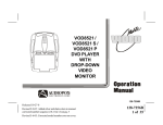
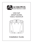
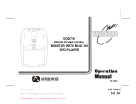
VOH8512
DROP-DOWN
VIDEO
MONITOR
VOD705
®
ELECTRONICS CORP.
128-7297
128-7297
1 of 20
Important Notice
An LCD panel and/or video monitor may be installed in a motor vehicle and visible to the driver if the LCD panel or video monitor is used
for vehicle information, system control, rear or side observation or navigation. If the LCD panel or video monitor is used for television
reception, video or DVD play, the LCD panel or video monitor must be installed so that these features will only function when the vehicle
is in “park” or when the vehicle’s parking brake is applied.
An LCD panel or video monitor used for television reception, video or DVD play that operates when the vehicle is in gear or when the
parking brake is not applied must be installed to the rear of the driver’s seat where it will not be visible, directly or indirectly, to the
operator of the motor vehicle.
Warnings
Do not use any solvents or cleaning materials when cleaning the video monitor.
Do not use any abrasive cleaners, they may scratch the screen. Use only a lightly dampened lint free cloth to wipe the screen if it is dirty.
Lock the LCD screen in the fully closed position when not in use.
Before putting on headphones always adjust the volume setting to the lowest position.
Remember to leave the dome light switch in the off or auto positions when the vehicle is unattended, as the dome lights, if left on, can drain
the vehicle’s battery.
Do not put pressure on the screen.
Caution children to avoid touching or scratching the screen, as it may become dirty or damaged.
Television Reception
This entertainment system is designed primarily for viewing prerecorded movies or playing video games. Television reception in a moving
vehicle will be limited and in some areas will not be possible due to weak and variable signal strength. Television viewing in a stationary
vehicle will result in an improvement, but may still be marginal due to signal strength. The quality of the picture will not be consistent with
home TV reception. Reception may be affected by weather and distance from TV station. A weak signal may cause the picture to roll, be
snowy, or cause some color loss.
-2 -
128-7297
2 of 20
Congratulations on your purchase of the Audiovox VOH8512
Drop-Down Video /Monitor. The VOH8512 has been designed
to give you and your family many years of video entertainment in
the mobile environment. Please read the directions that follow
to familiarize yourself with the product and to ensure that you
obtain the best results from your equipment.
Please note: Installation options vary, see the individual owner’s
manuals for each component in your system to obtain a full
understanding of each component’s operation.
Safety Precaution
For safety reasons, when changing video media it is
recommended that the vehicle is not in motion, and that you do
not allow children to unfasten seat-belts to change video media
or make any adjustments to the system. System adjustments
can be accomplished using the remote control, while seatbelts remain fastened. Enjoy your Audiovox entertainment
system but remember the safety of all passengers remains the
number one priority.
8.5” TFT Active Matrix Color LCD Monitor
OSD (On Screen Display) For Control of Picture
Quality, Display of Source Selection
Three Source Selection (AV1/AV2/AUX)
Video Display ON/OFF Control (when LCD Panel
is Opened and Closed)
Forward and Rear IR Sensor
Infrared Transmitter for IR Wireless Headphones
Dome Lights with Built-in Three Position Switch
TV Tuner (Optional)*
Backlit controls for Low Light operation
Five Frequency Wireless FM Modulater
Full Function Remote Control
Features
–
–
–
–
–
–
–
–
–
–
–
* Part Number PODTVT
-3-
128-7297
3 of 20
4
Controls and Indicators Diagram
5
3
4
6
2
12
7
1
11
9
8
10
14
-4 -
13
128-7297
4 of 20
Control Function Descriptions
1. Infrared Transmitter and Sensor – Use to transmit audio
to the wireless headphones. Also allows the remote control
to operate the VOH8512 and to control other accessories in
the system.
2. POWER Button – Used to turn the system ON/OFF. Bright
red when system is on, dim when off.
3. Three position Dome Light Switch
• Auto – Automatically switches on the dome lights in
conjunction with the vehicle’s interior illumination.
• Off – The dome lights will not turn on in this position.
• On – Turns on the dome lights.
4. Dome Lights – Provide additional interior illumination.
5. ( – ) Button – Picture quality adjustment (decrease).
6. ( + ) Button – Picture quality adjustment (increase).
7. PICTURE SELECT Button – Display picture adjustment
mode (Brightness, Contrast, Color & Tint)
8. Screen Release – Moves in direction of the arrow to release
the drop down screen.
9. Drop Down LCD Panel
-5-
10. IRT ON/OFF – Turn Infrared Transmitter power On/Off.
11. FM Select Button – When this button is pressed it will turn
on the wireless FM Modulator and then cycle through FM
frequencies (FM Off, Channel 1, 88.3MHz; Channel 2,
88.7MHz; Channel 3, 89.1MHz; Channel 4, 89.5MHz;
Channel 5, 89.9MHz).
12. SOURCE Select – Used to select one of the three sources
(AV1, AV2 ,AUX)
13. AUX – AUX input jack.
14. REAR Remote Sensor Eye – Allows the remote control to
operate the VOH8512, and control other accessories,
connected to the system.
128-7297
5 of 20
BATTERY COVER
Remote Control Operation
Battery Installation
Before attempting to operate your Remote Control, install the
batteries as described below.
1) Turn the Remote Control face down. Using a fingernail,
lift the battery cover off.
2) Install two “AAA” batteries as shown. Make sure that
proper polarity (+ or -) is observed.
3) Align the cover tabs with the remote control and press
down until the cover clicks.
The remote control will operate the VOH8512 and most Audiovox
VCP’s. It is not a universal remote control and will not control
equipment from other manufacturers.
-6 -
128-7297
6 of 20
Remote Control Function Descriptions
*Function control is available on the unit and the remote control.
** Not used in this model
*** Function only available if optional TV Tuner is installed.
1. POWER Button*
Press this button to turn the VOH8512 on. Press the button again to turn the VOH8512 off.
2. SOURCE Button*
Each time the button is pressed, the audio / video source will change: AV1, AV2, AUX.
3. AUTO MEMORY Button (AUTO PROGRAM Button)***
When the AUTO MEMORY button is pressed, all channels are searched and channels that are detected with signals of
sufficent levels are automatically stored.
4. SKIP/SEARCH Button***
This button selects betweeen SKIP and SEARCH mode. In “SKIP mode” the TV tuner will tune and stop on channels that are
programmed into memory the when CHANNEL UP/DOWN buttons are used. When the SKIP mode is disabled, the TV will
stop on all active channels.
5. ERASE/WRITE Button***
While tuned to a channel, pressing this button will store or erase the channel from memory. The stored channel numbers are
displayed in “GREEN” and the erased channel numbers are displayed in “RED”.
6. Channel Up ( ) Button***
Use this button to increase the channel number to the desired channel and to scroll upward in menu options.
-7-
128-7297
7 of 20
7. MUTE Button
Press this button to mute the audio.
Pressing the button again restores the sound to the previously set level.
8. ENTER Button**
Used to implement a selected setting or menu option.
9. LEFT ( ) Button**
Allows the user to shift left in the menu options.
10. MENU Button**
Allows the user to access the main menu.
11. RETURN Button**
Allows the user to return to the menu while PBC on.
Note : This function only present on VCD 2.0.
12. TV Mode Select Button
Switches certain function keys on the remote control for TV functions.
13. DVD Mode Select button**
Switches certain function keys on the remote control for DVD functions.
-8 -
128-7297
8 of 20
Display current TITLE , CHAPTER & elapsed time
Display current SUBTITLE
Display current AUDIO language & channel
Display current surround mode
Display current ANGLE
Display A-B current status
Display REPEAT current status
Display off
DVD Player Perform
14. DISPLAY Button**
Press to display DVD Disc current information.
Press DISPLAY button
Once
Twice
3 times
4 times
5 times
6 times
7 times
8 times
15. FM TRANSMITTER ON/OFF Button
Turns the FM Modulator ON/OFF.
16. AUDIO Button**
Press this button to display and select the desired AUDIO language. Each time the button is pressed, the language or track
changes. NOTE: The languages & tracks you can select are vary from disc to disc.
-9-
128-7297
9 of 20
2X
3X
4X
1/2
1/3
1/4
OFF
OSD
ZOOM picture 2 times
ZOOM picture 3 times
ZOOM picture 4 times
Reduces picture to 1/2 normal size
Reduces picture to 1/3 normal size
Reduces picture to 1/4 normal size
Returns to normal size
DVD Player Perform
17. ZOOM Button – Press this button to zoom the picture. **
Press ZOOM button
Once
Twice
3 times
4 times
5 times
6 times
7 times
18. PAUSE ( ) Button**
Allows the user to pause the playback.
!) Button**
19. STOP (!
Disc playback will be stopped.
20. PREVIOUS ( ) Button**
Allows the user to return to the previous chapter or track.
21. NEXT ( ) Button**
Allows the user to skip to the next chapter or track.
22. REV (
) Button**
Allows the user to search in a backward direction at 2, 4, 8, 16 and 32 times the normal speed.
-10-
128-7297
10 of 20
23. FWD (
) Button**
Allows the user to search in a forward direction at 2,4,8, 16 and 32 times the normal speed.
24. PLAY ( )Button**
Press this button to activate the play mode when a disc is loaded into the disc compartment.
25. ANGLE Button**
Press this button to display and select the available camera angles. Each time the button is pressed, the angle will change.
NOTE: The number of angles vary from disc to disc.
26. SUBTITLE Button**
Press this button to display and select the available subtitle language in DVD. Each time the button is pressed, the subtitle
language changes. NOTE: The type & number of languages for subtitles vary from disc to disc.
27. SOURCE SELECT Button**
With FM ON, used to select the Audio source to the FM Modulator, POD audio or SAT Audio (Second IR input).
With FM OFF, used to select from SAT Audio or Car Audio.
28. CHANNEL SELECT Button* (FM Select)
Selects the FM modulator Frequency (Frequency 1, 88.3MHz, Frequency 2, 88.7MHz, Frequency 3, 89.1MHz, Frequency 4,
89.5MHz, Frequency 5, 89.9MHz).
29. VCP Mode Select button
Switches certain function keys on the remote control for VCP functions.
30. Screen Mode Button
Allows the user to change the screen Aspect Ratio, 4:3 or 16:9.
-11-
128-7297
11 of 20
31. A-B Button**
Allows the user to repeat playback of a DVD or CD from point A to point B.
32. REPEAT Button**
Allows the user to repeat a chapter, title, track, or all of a DVD, CD or MP3.
33. Channel Down ( ) Button***
Use this button to decrease the channel number to the desired channel and to scroll downward in the menu options.
34. SETUP Button**
Allows the user to access the DVD setup menu and select various playback options (Display, OSD Language, Defaults,
Parental Control, Password, Exit Setup).
35. RIGHT (
) Button**
Allows the user to shift to the right in the menu options.
36. PIX Button (PICTURE SELECT)*
Each time this button is pressed, the OSD will display the “adjustment bars” for BRIGHTNESS, CONTRAST, COLOR or TINT.
Once the desired adjustment bar is displayed, use the VOLUME UP/DOWN buttons to adjust the setting. The display will
automatically turn off if no adjustments are made within 6 seconds, or if any other button is pressed.
37. (–) Button*
Used to make picture adjustments in picture select mode.
-12-
128-7297
12 of 20
38. (+) Button*
Used to make picture adjustments in picture select mode.
39. NUMBER Buttons***
Allows the user to directly access specific TV channels.
40. IRT A ON/OFF Buttons*
Turn Infrared Transmitter power ON/OFF for IR Wireless Headphone Channel A.
41. IRT B ON/OFF Buttons**
Turn Infrared Transmitter power ON/OFF for IR Wireless Headphone Channel B.
42. EJECT ( )Button**
Used to eject the disc.
-13-
128-7297
13 of 20
Turning the VOH8512 ON or OFF
1. Sliding the screen release lock forward will unlock the LCD screen and it will drop down slightly. Pivot the screen downward until
a comfortable viewing angle is reached. The hinge friction will hold the screen in position while the system is in use.
2. Pressing the power button on the unit or the remote control will turn the system on or off alternately. When in use the internal
backlighting will illuminate the controls.
Dome
Light
Switch
Infrared
Transmitter
3. Press the source buttonon the unit or the remote control to select the desired source. Adjust the viewing angle by pivoting the
screen to optimize the picture quality.
4. Remember to turn the unit off and pivot the LCD to the locked position when not in use.
Overhead Dome Lights
The lights integrated into the VOH8512 are controlled by a
three position slide switch. Sliding the switch to the on position
will turn the lights on. The off position will prevent the lights
from turning on at all times, and the auto position will allow
the lights to turn on and off with the vehicle’s interior lighting.
Refer to the Installation Manual for the wire connections. Do
not leave the vehicle unattended with the dome light switch in
the on position, as this could result in a discharged battery.
-14-
128-7297
14 of 20
Remote Sensor
The VOH8512 incorporates two Infrared sensors which relay signals from
the remote control to allow the unit to be controlled simply by pointing its
remote control at the remote sensor eye. The repeater function allows
control of auxiliary equipment such as an Audiovox DVD Player or Video
Cassette Player. The infrared sensor can relay signals from most
manufacturer’s remote controls to its respective component connected to
the AV input. In this case you must use the remote control supplied with
the component.
Accessories
Wireless Headphones
Remote Sensor Eye
Remote Sensor Eye
The VOH8512 includes a built-in infrared transmitter for use with Audiovox wireless headphones (Part Number MVIRHS). The
volume can then be adjusted using the controls on each headset. Any number of wireless headphones may be used but they must
be used within a line of sight from the transmitter, as infrared transmissions, like visible light travel only in a straight line. See the
documentation accompanying your Audiovox wireless headphones.
-15-
128-7297
15 of 20
Wireless FM Modulator
The VOH8512 is equipped with buit-in wireless FM Modulator*, that allows you to listen to the VOH8512 audio signal by tuning your
vehicle’s radio to the selected frequency, (88.3, 88.7, 89.1, 89.5, 89.9MHz). This feature is accessed by using either the FM transmitter
buttons on the remote (ON/OFF, Channel Select) or the FM Select button on the unit. Whenever the FM modulator is on, broadcast
reception on the vehicles radio will be poor. Switching off the FM modulator will allow normal radio reception.
*NOTE: In certain areas where there are a large number of FM radio stations (e.g. large cities, urban areas), the reception of the FM
signal from the overhead pod may not be satisfactory, resulting in static, distorted sound or signal bleed thru from strong local radio
stations. This is not a defect in the product, but the result of a stronger local radio station overpowering the wireless FM transmitter in
your overhead pod.
If wireless reception is unsatisfactory, an optional wired relay box (Audiovox P/N SIRSWB) can be installed which will improve audio
quality. Please contact the installer if this is the case with your product.
AV1/AV2 Input
The AV1/AV2 video input may be connected to a DVD Player, video game system, or other audio / video devices. To access the A/
V inputs, turn the VOH8512 on and press the source button on the VOH8512 or the Source button on the remote control until “AV1”
or “AV2” is displayed on the screen. Turn the video source component on with its power button or remote control. The VOH8512 is
now ready to play the audio and video signals from the source connected to AV1/AV2 input. The AV1/AV2 input requires a 8010730
cable.
AUX A/V Input
The VOH8512 will accept an audio/video signal input through the AUX jacks located on the side of the unit. The audio/video device
could be a video game system, video camera, or other input device (use the supplied AV adaptor cable).
Video Out
The VOH8512 provides a video output for an optional video monitor(s). This output will provide a video signal that duplicates the
signal displayed by the VOH8512 to an additional monitor or video display. Please see your installer for more inofrmation.
-16-
128-7297
16 of 20
Troubleshooting
SOLUTION
• Check the condition of the vehicle’s radio antenna.
• Verify that the antenna is fully raised.
• If a relay box (SIRSWB) has been insatalled, make sure that the FM Modulator is turned OFF.
• If a wired FM modulator has been installed, verify that it is turned OFF by using the remote or switch.
PROBLEM
Poor in vehicle
radio reception
• Verify that the batteries in the remote are fresh.
• Verify that the remote sensor eye is not obstructed.
• Verify that the infrared transmitter is affixed over the sensor eye of the component to be controlled.
appropriate jacks.
• Make sure your AV Source is connected properly. Make sure all cables are securely inserted into the
IR sensor
inoperative
No sound or
distorted sound
• If you are using the IR headphones, make sure you turn on the IR power.
• Make sure the FM Modulator is ON and the proper Frequency has been selected.
-17-
128-7297
17 of 20
136-3855
Replacement Parts
Remote Control
Video Output
Video Display System
Backlight life
Storage Temperature
Operation Temperature
Pixels
Resolution
LCD Backlighting
12V DC
1.0Vp-p @ 75 ohms
NTSC / PAL
10,000 Hours
-4 - 176º F (-20 - 80º C)
32 -140º F (0 - 60º C)
336,960
1440 x 234
Edge Light Tube
Specifications
Power Source
1”H x 9.5”W x 8.75”
25.4mmH x 241.3mmW x 222.25mmD
Dimensions
-18-
128-7297
18 of 20
12 MONTH LIMITED WARRANTY
Applies to Audiovox Mobile Video Products
AUDIOVOX ELECTRONICS CORP. (the Company) warrants to the original retail purchaser of this product that should this product or any part
thereof, under normal use and conditions, be proven defective in material or workmanship within 12 months from the date of original purchase,
such defect(s) will be repaired or replaced with reconditioned product (at the Company's option) without charge for parts and repair labor.
To obtain repair or replacement within the terms of this Warranty, the product is to be delivered with proof of warranty coverage (e.g. dated
bill of sale), specification of defect(s), transportation prepaid, to the Company at the address shown below.
This Warranty does not extend to the elimination of externally generated static or noise, to correction of antenna problems, to costs incurred
for installation, removal or reinstallation of the product, or to damage to tapes, discs, speakers, accessories, or vehicle electrical systems.
This Warranty does not apply to any product or part thereof which, in the opinion of the Company, has suffered or been damaged through
alteration, improper installation, mishandling, misuse, neglect, accident, or by removal or defacement of the factory serial number/bar code
label(s). THE EXTENT OF THE COMPANY'S LIABILITY UNDER THIS WARRANTY IS LIMITED TO THE REPAIR OR REPLACEMENT
PROVIDED ABOVE AND, IN NO EVENT, SHALL THE COMPANY'S LIABILITY EXCEED THE PURCHASE PRICE PAID BY PURCHASER FOR
THE PRODUCT.
This Warranty is in lieu of all other express warranties or liabilities. ANY IMPLIED WARRANTIES, INCLUDING ANY IMPLIED WARRANTY
OF MERCHANTABILITY, SHALL BE LIMITED TO THE DURATION OF THIS WRITTEN WARRANTY. ANY ACTION FOR BREACH OF ANY
WARRANTY HEREUNDER INCLUDING ANY IMPLIED WARRANTY OF MERCHANTABILITY MUST BE BROUGHT WITHIN A PERIOD OF 24
MONTHS FROM DATE OF ORIGINAL PURCHASE. IN NO CASE SHALL THE COMPANY BE LIABLE FOR ANY CONSEQUENTIAL OR
INCIDENTAL DAMAGES FOR BREACH OF THIS OR ANY OTHER WARRANTY, EXPRESS OR IMPLIED, WHATSOEVER. No person or
representative is authorized to assume for the Company any liability other than expressed herein in connection with the sale of this product.
Some states do not allow limitations on how long an implied warranty lasts or the exclusion or limitation of incidental or consequential damage
so the above limitations or exclusions may not apply to you. This Warranty gives you specific legal rights and you may also have other rights
which vary from state to state.
U.S.A. : AUDIOVOX ELECTRONICS CORPORATION, 150 MARCUS BLVD., HAUPPAUGE, NEW YORK 11788 " 1-800-645-4994
CANADA : CALL 1-800-645-4994 FOR LOCATION OF WARRANTY STATION SERVING YOUR AREA
-19-
128-7297
19 of 20
© 2004 Audiovox Electronics Corp., Hauppauge, NY 11788
For Customer Service
Visit Our Website At
WWW.audiovox.com
Product Information, Photos,
FAQ’s Owner’s Manuals
128-7297
128-7297
20 of 20