1
Version 2.0 Manual Supplement
E
AW4416 Version 2.0 Manual Supplement
This manual supplement explains the functions and specifications
that have been added or changed in version 2.0 of the AW4416’s system software. “Operation” explains how to use the new functionality,
and “Reference” provides detailed explanations of all items in the
pages that were added. Since revisions have also occurred in the
MIDI data format in the appendices, this material is also provided.
Contents
Operation
Reference
Extensions to the Quick Rec function ............ 3
Quickly assign input sources to tracks.......... 3
QUICK REC screen ............................ 23
Quick Rec 2 page .........................................23
Shortcut key definitions................................. 5
Added/modified MIDI functions.................... 6
Changes in the MIDI Setup page/
MIDI Sync page ......................................... 6
Using control changes to operate
AW4416 parameters .................................. 9
Using parameter changes to perform
AW4416 operations................................. 11
Transmitting internal AW4416 settings
via MIDI (Bulk Dump).............................. 11
Newly added MIDI Remote function.......... 13
Additional functionality for Automix .......... 19
Mini YGDAI plug-in system compatible
I/O card operations................................... 21
Backing up an I/O card .............................. 21
Restoring to an I/O card ............................. 22
2
UTILITY screen.................................. 25
CTRL Key Asgn. page....................................25
MIDI screen ...................................... 27
CTL Asgn. page.............................................27
Bulk Dump page...........................................31
Remote A 1-8/Remote A 9-16/
Remote B 1-8/Remote B 9-16 pages...........33
MIDI data format .........................................37
Version 2.0 Manual Supplement
Operation
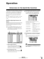
Extensions to the Quick Rec function
The Quick Rec screen now has two pages: Quick Rec
1 and Quick Rec 2. Operations corresponding to what
was the previous Quick Rec page are performed in
the Quick Rec 1 page, and the newly added Quick
Rec 2 page allows the various input signals/input
channels to be freely patched to the tracks of the
recorder.
2
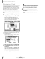
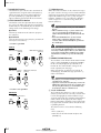
To change the input source that is assigned
to an input channel, move the cursor to
the number box of the corresponding
channel, and turn the [DATA/JOG] dial.
By using the appropriate page (Quick Rec 1 or Quick
Rec 2), you can make patching settings more efficiently.
Quickly assign input sources to
tracks
The following types of input source can be
assigned to an input channel.
• AD 1–AD 8 .............Input signals from INPUT
1–8 jacks
By using the Quick Rec 2 page, you can quickly
assign any input source/input channel to a recorder
track. Here’s how.
1
• SL1-1–SL1-8 ............Inputs 1–8 from an I/O
card (slot 1)
In the WORK NAVIGATE section, press the
[Quick Rec] key → [F2] (Quick Rec 2) key.
• SL2-1–SL2-8 ............Inputs 1–8 from an I/O
card (slot 2)
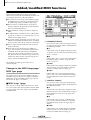
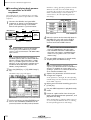
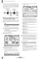
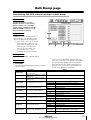
The Quick Rec 2 page will appear. This page displays the following information.
• DIN L/DIN R ..........L or R channels from the
DIGITAL STEREO IN jack
1
• SMP 1–SMP 8 ..........Sampling pads 1–8
2
• MET ........................Internal metronome
3
In the MIX.CH area, move the cursor to the
patch-source jack, and press the [ENTER]
key.
The corresponding input channel will be highlighted, and selected as the patch-source.
Tip!
A MIX.CH (Input channel)
This area shows the type of input signal that is
assigned to each input channel 1–16. The
symbols (jacks) displayed at the right of this area
indicate the direct output of each input channel.
If you move the cursor to a highlighted input channel
and press the [ENTER] key once again, the selection
will be cancelled.
B REC.TR (Recorder track)
This area shows tracks 1–16 (Tr1–Tr16). The
symbols (jacks) displayed at the left of this area
indicate the input to each track.
Version 2.0 Manual Supplement
3
AW4416 Version 2.0 Manual Supplement
4
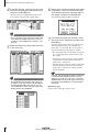
In the REC.TR area, move the cursor to the
jack for the desired patch-destination track,
and press the [ENTER] key.
6
The patch-source and patch-destination in the
screen will be connected by a patch cable.
When you are finished making patch cable
connections, move the cursor to the EXECUTE button located in the lower right of
the display, and press the [ENTER] key.
The following popup window will appear.
Tip!
• You may perform steps 3 and 4 in reverse order.
• It is also possible to connect the direct output of the
same channel to multiple tracks. However, it is not
possible to connect multiple direct outputs to a single track.
5
Make connections for other input channels
in the same way.
7
To execute the Quick Rec function, move
the cursor to the OK button and press the
[ENTER] key.
To cancel the operation, move the cursor to the
CANCEL button and press the [ENTER] key.
When you execute Quick Rec, the internal settings of the AW4416 will change as follows.
• The input patch and recorder input settings will
be set according to the settings of the Quick
Rec 2 page.
• Assignments to the stereo bus will be forcibly
cancelled for any input channel to which a
patch cable is connected.
• Channel library number 01 will be recalled for
the monitor channel of any track to which a
patch cable is connected, restoring it to the
default condition.
Tip!
Tip!
• To cancel a specific patch cable, move the cursor to
the CLEAR button located at the right of the corresponding recorder input, and press the [ENTER] key.
• To cancel all patch cables, move the cursor to the
ALL CLEAR button located at the upper right of the
display, and press the [ENTER] key.
4
If desired, each input channel to which a patch cable
is connected can be initialized when you execute
Quick Rec. To do this, move the cursor to the FLAT/
CURRENT button located in the upper left of the display, and press the [ENTER] key to make the button
read “FLAT.”
[Reference pages]
Details on the Quick Rec 2 page → P.23
Version 2.0 Manual Supplement
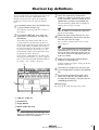
Shortcut key definitions
The new version of the system program lets you assign
desired functions to various combinations of the
[SHIFT] key located at the right of the display (the
[CTRL] key), in order to create your own shortcut
keys.
1
3
The corresponding symbol will be highlighted,
allowing you to assign a function.
In the UNIT section, press the [UTILITY] key
→ [F5] (CTRL Key Assign) key.
Tip!
The CTRL Key Asgn. page added in version 2.0
will appear.
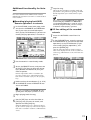
2
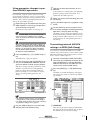
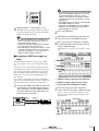
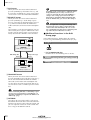
In the RIGHT SHIFT KEY area, move the
cursor to the CTRL button, and press the
[ENTER] key.
When the AW4416 is in its initial state, all shortcut
keys are set to No Assign.
4
The buttons in the RIGHT SHIFT KEY area are
used to switch the function of the [SHIFT] key
located at the right of the display. When you turn
on the CTRL button, the [SHIFT] key located at
the right of the display will function as a [CTRL]
key to access shortcuts. (Even in this case, the
function of the [SHIFT] key located at the left of
the display will not be affected.)
If you turn the CTRL button on, you will be able
to assign specific functions (e.g., access a page or
turn a certain function on/off) to combinations of
the [CTRL] + [F1] – [CTRL] + [F5] keys.
Select the shortcut key combination
(CTRL+F1–CTRL+F5) to which you want to
assign a function, move the cursor to that
combination, and press the [ENTER] key.
Move the cursor to the function list, and
use the [DATA/JOG] dial to select the function that you want to assign.
For a list of the functions that can be selected,
refer to page 25.
Tip!
If you select SCENE RECALL as the assigned function,
a field allowing you to specify the scene number will
appear at the right of the function list. Move the cursor to this area, and use the [DATA/JOG] dial to specify the scene number.
5
Move the cursor to the ASSIGN button,
and press the [ENTER] key.
A popup window will appear, asking you to confirm the assignment.
1
3
6
To confirm the assignment, move the cursor to the OK button and press the [ENTER]
key.
7
To execute the assigned function, hold
down the [CTRL] key (the [SHIFT] key at
the right of the display), and press the corresponding function key.
[Reference pages]
For details on the CTRL Key Asgn. page → P.25
2
4
A CTRL+F1 –CTRL+F5
B Function list
C Assign button
D RIGHT SHIFT KEY area
Tip!
To return the [SHIFT] key located at the right of the
display to its normal function, move the cursor to the
SHIFT button and press the [ENTER] key.
Version 2.0 Manual Supplement
5
AW4416 Version 2.0 Manual Supplement
Added/modified MIDI functions
MIDI-related functionality has been significantly
enhanced in version 2.0. The following functions and
specifications have been added or modified.
● The various items in the previous MIDI Setup page
and MIDI Sync page have been reorganized into
the MIDI Setup 1 page and MIDI Setup 2 page.
● You can now use control changes or parameter
changes to operate the parameters of the AW4416
from an external MIDI device.
● Internal AW4416 settings can now be output via
MIDI.
● A “MIDI Remote” function has been added, allowing you to use faders 1–16 and [ON] keys 1–16 to
control external MIDI devices.
● As an MTC output destination, you can now select
MIDI/TO HOST/OPTION (option slot 2) in addition
to the previous choice of the MTC OUT connector.
● MTC is now transmitted from the MTC OUT connector at all times.
● As the port used to transmit/receive MIDI messages, you can now select OPTION (option slot 2)
in addition to the previous choices of MIDI/TO
HOST. This setting will be valid when a I/O card
able to transmit/receive MIDI messages (such as the
mLAN card “MY8-mLAN” expected to go on sale
soon) is installed in option slot 2.
The additions and changes for each item are
explained below.
Changes in the MIDI Setup page/
MIDI Sync page
The various items in the previous MIDI Setup page
and MIDI Sync page have been reorganized into the
MIDI Setup 1 page and MIDI Setup 2 page. The content of the new pages is as follows.
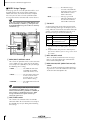
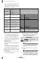
■ MIDI Setup 1 page
Here you can select the MIDI transmit/receive channels, turn transmission and reception of various MIDI
messages on/off, and make settings related to MIDI
synchronization.
1
2
3
4
5
7
8
9
6
K
J
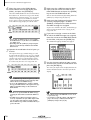
A PROGRAM CHANGE
Here you can make settings for program change
message transmission/reception. Each button has
the following function.
● TX
If this button is on, the program change number
assigned to a scene will be transmitted when that
scene is recalled.
● RX
If this button is on, a scene will be recalled when
the program change number assigned to that
scene is received.
● OMNI
If this button is on, program changes of all MIDI
channels will be received regardless of the Rx
CH (Receive MIDI channel) setting (8).
● ECHO
If this button is on, received program changes
will be “thru-ed” (retransmitted) without change
from the MIDI OUT connector/TO HOST connector.
B CONTROL CHANGE
Here you can make settings for control change
message transmission/reception. Each button has
the following function.
● TX
If this button is on, operating a parameter of the
AW4416 will cause the control change assigned
to that parameter in the CTL Asgn. page to be
transmitted.
● RX
If this button is on, receiving a control change
will cause the AW4416 parameter assigned to
that control change in the CTL Asgn. page to
change.
● OMNI
If this button is on, control changes of all MIDI
channels will be received regardless of the Rx
CH (Receive MIDI channel) setting (8).
6
Version 2.0 Manual Supplement
H Rx CH (Receive channel)
● ECHO
If this button is on, received control changes will
be “thru-ed” (retransmitted) without change from
the MIDI OUT connector/TO HOST connector/
option slot.
C PARAMETER CHANGE
Here you can make transmission/reception settings for system exclusive messages that control
the AW4416’s parameters (parameter change
messages). Each button has the following function.
● TX
If this button is on, operating a parameter of the
AW4416 will cause the corresponding parameter
change to be transmitted.
● RX
If this button is on, receiving a parameter change
will cause the corresponding AW4416 parameter
to change.
● ECHO
If this button is on, received parameter changes
will be “thru-ed” (retransmitted) without change
from the MIDI OUT connector/TO HOST connector/option slot.
D BULK
Here you can make settings for bulk data reception. If the BULK RX button is on, the AW4416
will be able to receive bulk dump data and messages requesting a bulk dump (bulk dump
requests).
This specifies the channel (1–16) of the MIDI
messages that receive received by the AW4416.
I MMC DEVICE
This sets the device ID (1–127) used to distinguish between devices when MMC (MIDI
Machine Control) messages are used to perform
remote control between the AW4416 and external MIDI devices.
J MMC MODE
Use the following three buttons to make settings
for MMC reception and transmission.
● OFF button
If this button is on, the AW4416 will not transmit
or receive MMC.
● MASTER button
If this button is on, the corresponding MMC
command will be transmitted from MIDI OUT/
TO HOST connector/option slot when you operate the transport of the AW4416.
● SLAVE button
If this button is on, the AW4416 will obey MMC
commands received from MIDI IN/TO HOST
connector/option slot.
Tip!
In order to use MMC, the device ID of the AW4416
and the external MIDI device must match. The device
ID of the AW4416 is specified by the MMC DEVICE
setting (9).
K SYNC AVERAGE
E MTC SYNC
When using MTC (MIDI Time Code) to synchronize the AW4416 song with an external MIDI
device, this setting selects whether the AW4416
will function as the MTC master (MASTER button
on) or MTC slave (SLAVE button on).
In the previous version, the MTC MASTER indicator in
the level meter/counter was lit or dark depending on
whether MTC output from the MTC OUT connector
was turned on or off. However in version 2.0, MTC is
output from the MTC OUT connector at all times. For
this reason, the lit/dark status of the MTC MASTER
indicator now indicates the on/off state of MTC output from the MIDI OUT connector/TO HOST connector/option slot 2.
F SYNC OFFSET
When using the AW4416 as an MTC slave, this
lets you shift the absolute time of the AW4416
relative to the received MTC. The range is “24:00:00:00.00” – “+24:00:00:00.00”
G Tx CH (Transmit channel)
This specifies the channel (1–16) of the MIDI
messages that will be transmitted from the
AW4416.
This sets the permissible range of variation in
MTC timing when using the AW4416 as an MTC
slave. Select one of the following three settings.
● OFF button
If this button is on, the permissible range will be
the least, and the AW4416 will synchronize to
incoming MTC with the highest precision. However if MTC with significant variation is received,
synchronization may be lost or become unstable.
This setting is suitable when two AW4416 units
are being operated in synchronization.
● 1 button/2 button
Turning on the 1 button will increase the permissible range, and turning on the 2 button will set
the permissible range to the maximum setting.
These settings are suitable when an external
device with significant variation in MTC (such as
a tape recorder or computer-based sequencer) is
used as the MTC master.
The SYNC AVERAGE setting is valid only when the
word clock source is set to “INT” (internal clock). If
the AW4416 is synchronized to an external clock,
operation will automatically be the same as when this
setting is OFF.
Version 2.0 Manual Supplement
7
AW4416 Version 2.0 Manual Supplement
■ MIDI Setup 2 page
In this page you can select the port that will be used
for MIDI transmission and reception: MIDI OUT/
THRU connectors, TO HOST connector, or option
slot. Here you can also select the synchronization
messages that will be transmitted to external devices.
Tip!
In this page, signal routes along which MIDI messages
flow are shown by a solid line ( | ), and signal routes
along which MIDI messages do not flow are shown by
a hollow line ( || ).
3
• THRU......................The MIDI messages
received at the MIDI IN
connector will be retransmitted from the OUT/
THRU connector.
• OUT........................Messages generated
within the AW4416 will
be transmitted from the
OUT/THRU connector.
C TO HOST
Set the transmission speed of the TO HOST connector according to the type of computer you are
using. Move the cursor to the TO HOST connector
graphic, and turn the [DATA/JOG] dial to select
the transmission speed from the following.
Setting
5
Platform
Speed
PC1
NEC PC-9800/9821 series*1
31.25 kbps
PC2
IBM PC compatible, NEC
PC-9800/9821 series*1
38.4 kbps
MAC
Apple Macintosh series*2
31.25 kbps
*1 Select PC1 or PC2 according to the driver you are
using.
*2 Only for models that provide a modem/printer
port. On the software you are using, set the clock
to “1 MHz.”
4
1
2
A MIDI/HOST/OPTION switch
This selects the port that will be used to transmit/
receive MIDI messages. Move the cursor to this
area and press the [ENTER] key to cycle through
the following three settings.
• MIDI .......................The MIDI IN connector
and MIDI OUT/THRU
connector will be used.
D MTC ON/OFF switch
This is an on/off switch for the MTC messages
that are sent to the MIDI OUT connector/TO
HOST connector/option slot.
E MIDI CLK ON/OFF (MIDI Clock on/off)
switch
This is an on/off switch for the MIDI Clock messages that are sent to the MIDI OUT connector/
TO HOST connector/option slot.
• HOST ......................The TO HOST connector
will be used. The transmission speed is set by
the TO HOST setting.
• OPTION..................The OPTION I/O slot will
be used.
Tip!
The OPTION setting is valid only if an I/O card that
can transmit/receive MIDI messages (such as the
mLAN card “MY8-mLAN”; planned for availability in
the near future) is installed in option slot 2. MIDI
message transmission/reception cannot be performed via option slot 1.
B OUT/THRU switch
This switches the function of the OUT/THRU
connector. Move the cursor to this area and press
the [ENTER] key to cycle through the following
two settings.
8
Version 2.0 Manual Supplement
Using control changes to operate
AW4416 parameters
2
Move the cursor to the CTL CHG. numerical box, and use the [DATA/JOG] dial to
select the control change number that you
want to assign.
3
Move the cursor to the various fields in the
PARAMETER area, and use the [DATA/JOG]
dial to set the parameter and its values.
In version 2.0, AW4416 parameters can be assigned
to control changes, so that AW4416 operations can be
recorded/played back on a MIDI sequencer or other
external MIDI device.
■ Assigning a parameter to a control change
1
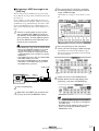
Press the [MIDI] key → [F4] (CTL Asgn.)
key.
The MIDI screen CTL Asgn. page added in version 2.0 will appear. In this page you can assign
AW4416 internal parameters to control change
numbers. Each part of the screen has the following function.
1
For the available parameters and values, refer to
page 28.
2
Tip!
Parameter 1
Parameter 3
Parameter 2
3
A CTL CHG. (Control change number)
Move the cursor to this area and use the [DATA/
JOG] dial to select a control change number
from the range of 0–95 and 102–119.
B PARAMETER
This area shows the parameter that is assigned to
each control change. In the left column (parameter 1), select the type of parameter that you want
to control. In the center and right columns
(parameters 2/3), specify the values required for
that parameter. Control change numbers to
which no parameter has been assigned will be
displayed as “NO ASSIGN.”
Of the parameters that can be assigned, channel
fader, AUX send, [ON] key, EQ, and pan operations
can be recorded in automix. By using automix to
record these operations, and using your MIDI
sequencer to record operations of the remaining
parameters, you can minimize the amount of MIDI
messages that are transmitted and received between
the AW4416 and your MIDI sequencer.
Control change numbers 0 and 32 are defined as
“Bank Select” (messages used to switch the voice
banks of a synthesizer, etc.). On some MIDI sequencers, bank select messages are handled differently than
other control changes, and therefore may not be suitable for use in parameter operations.
[Reference pages]
Details of the CTL Asgn. page → P.27
C INITIALIZE
This button resets the control change assignments
to the default state.
Tip!
For details on the parameters assigned to each control
change number when the AW4416 is in the default
state, refer to page 30.
Version 2.0 Manual Supplement
9
AW4416 Version 2.0 Manual Supplement
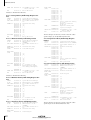
■ Recording/playing back parameter operations on a MIDI
sequencer
With these settings, operating a parameter on the
AW4416 itself will cause the control change
assigned in the CTL Asgn. page to be transmitted.
When a control change is received from an
external device, the corresponding parameter
will change.
Here’s how you can use control changes to record/
play back AW4416 parameter operations on a MIDI
sequencer.
1
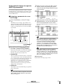
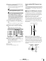
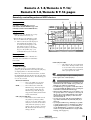
Connect the AW4416 and your MIDI
sequencer as shown in the following diagram, and make settings so that both
devices will operate in synchronization.
MTC
MTC master
PROFESSIONAL AUDIO WORKSTATION
AW4416
MTC slave
MTC OUT Control MIDI IN 1
connector changes connector
MIDI OUT/THRU
MIDI IN 2
connector Control connector
changes
MIDI IN
connector
MIDI
sequencer
MIDI OUT
connector
Move the cursor to the numerical boxes in
the MIDI CH. area, and use the [DATA/
JOG] dial to specify the transmit MIDI
channel and receive MIDI channel.
Tip!
Tip!
Make sure that “MIDI” is selected as the transmission/reception port for MIDI messages, and that
“OUT” is selected as the function of the MIDI THRU/
OUT connector.
• Normally you will set the transmit MIDI channel
and receive MIDI channel to the same setting.
• If the CONTROL CHANGE area OMNI button is
turned ON, control changes of all MIDI channels
will be received, regardless of the receive MIDI
channel setting.
When recording/playing back control changes on
your MIDI sequencer, make sure that the MIDI Thru
function (sometimes called “Patch Thru” or “MIDI
Echo”) of your MIDI sequencer is turned off. If this
function is on, the control changes transmitted from
the AW4416 will be immediately sent back to the
AW4416, causing malfunctions.
2
4
5
When recording parameter operations on your
sequencer, you should turn automix off (DISABLE). If
automix is on (ENABLE), the control changes corresponding to parameters recorded in the automix will
also be transmitted simultaneously.
Press the [MIDI] key → [F1] (MIDI Setup 1)
key.
The MIDI Setup 1 page will appear.
Put your MIDI sequencer in record mode,
and play back the AW4416 song.
6
Operate the parameters to which control
changes are assigned.
As the parameter is changed, the corresponding
control change will be transmitted, and recorded
on the MIDI sequencer.
7
8
9
3
10
Use the cursor keys and the [ENTER] key to
turn on the CONTROL CHANGE area TX
(transmit) button and RX (receive) button.
When you are finished recording, press the
[STOP] key.
Put your MIDI sequencer in playback-ready
mode.
Locate to a point earlier than where you
begin recording parameter operations, and
play back the song.
When control changes from the MIDI sequencer
are received by the AW4416 while it is running,
the corresponding parameter will change.
Version 2.0 Manual Supplement
Using parameter changes to perform AW4416 operations
In version 2.0, a type of system exclusive message
called “parameter changes” can be used (instead of
control changes) to operate internal parameters of the
AW4416. Here’s how to record/play back parameter
changes on your MIDI sequencer.
1
Make settings on the AW4416 and on your
MIDI sequencer so that they will operate in
synchronization using MTC.
For details on connections, refer to page 10.
5
As the parameter is changed, the corresponding
parameter change will be transmitted, and
recorded on the MIDI sequencer.
6
7
8
Tip!
2
Press the [MIDI] key → [F1] (MIDI Setup 1)
key.
The MIDI Setup 1 page will appear.
3
Use the cursor keys and the [ENTER] key to
turn on the PARAMETER CHANGE area TX
(transmit) button and RX (receive) button.
With these settings, operating a parameter on the
AW4416 itself will cause the corresponding
parameter change to be transmitted. When a
parameter change is received from an external
device, the corresponding parameter will
change.
When you are finished recording, press the
[STOP] key.
Put your MIDI sequencer in playback-ready
mode.
On the AW4416, locate to a point earlier
than where you begin recording parameter
operations, and play back the song.
The MIDI sequencer will begin playback in synchronization with the AW4416. When parameter
changes from the MIDI sequencer are received
by the AW4416, the corresponding parameter
will change.
Make sure that “MIDI” is selected as the transmission/reception port for MIDI messages, and that
“OUT” is selected as the function of the MIDI THRU/
OUT connector.
When recording/playing back parameter changes on
your MIDI sequencer, make sure that the MIDI Thru
function of your MIDI sequencer is turned off. If this
function is on, the parameter changes transmitted
from the AW4416 will be immediately sent back to
the AW4416, causing malfunctions.
Operate the desired parameters on the
AW4416.
Transmitting internal AW4416
settings via MIDI (Bulk Dump)
In version 2.0, settings of the MIDI screen and the
contents of the various libraries can be converted into
MIDI data (bulk data) and transmitted to an external
device such as a MIDI sequencer.
1
Connect the AW4416’s MIDI OUT/THRU
connector to the MIDI IN connector of the
external MIDI device, and the AW4416’s
MIDI IN connector to the MIDI OUT connector of the external MIDI device.
2
Press the [MIDI] key → [F5] (Bulk Dump)
key.
The MIDI screen Bulk Dump page will appear.
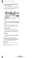
The various areas of the screen have the following functions.
1
Tip!
• The parameter change messages corresponding to
each parameter are fixed, and cannot be changed.
• For details on the parameters that can be controlled
by parameter changes, refer to page 47.
4
Put your MIDI sequencer in record mode,
and play back the AW4416 song.
2
3
4
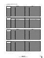
A CATEGORY
Move the cursor to the category of information
that you want to transmit as bulk data, and press
the [ENTER] key to select that category.
Version 2.0 Manual Supplement
11
AW4416 Version 2.0 Manual Supplement
If you select a category from the right column of
buttons (SCENE MEM.–REMOTE), move the cursor to the column at the far right, and turn the
[DATA/JOG] dial to select the content within that
category that will be transmitted.
Category
Values
SETUP MEM.
AW4416 settings other than the
following items
—
PGM. TABLE
Settings of the MIDI screen PGM
ASGN. page
—
CTL. TABLE
Settings of the MIDI screen CTL
ASGN. page
—
SCENE MEM.
The specified scene memory
PATCH LIBRARY
The specified patch library
CH LIBRARY
The specified channel library
EQ LIBRARY
The specified EQ library
DYN. LIBRARY
The specified dynamics library
EFF. LIBRARY
The specified effect library
AUTO MIX
MIDI REMOTE
01–96
Scene number 1–96
EDIT BUFFER
Current scene (current mixer settings)
ALL
All scene memories + current scene
01–20
Library number 1–20
ALL
All patch libraries
02–64
Library number 2–64
ALL
All channel libraries
41–128
Library number 41–128
ALL
All EQ libraries
41–128
Library number 41–128
ALL
All dynamics libraries
42–128
Library number 42–128
ALL
All effect libraries
1–16
Memory number 1–16
The specified automix
BUFFER
Current automix
ALL
All automixes + current automix
Settings of the REMOTE screen
REMOTE A–
REMOTE B
Settings of the REMOTE A (REMOTE A 1-8/9-16
pages) or B (REMOTE B 1-8/9-16 pages)
ALL
Settings of all pages of the REMOTE screen
B REQUEST button
When you move the cursor to this button and
press the [ENTER] key, a “bulk dump request”
message requesting the bulk dump data selected
in 1 will be transmitted from the MIDI OUT
connector/TO HOST connector/option slot.
4
If you selected a SCENE MEM.–REMOTE
button, move the cursor to the numerical
box at the right of the button, and use the
[DATA/JOG] dial to select the internal settings that you want to transmit.
This button is used when two AW4416 units are
connected by their respective MIDI IN/OUT connectors, and you want to copy scene memory or
library data from one unit to the other.
C TRANSMIT button
When you move the cursor to this button and
press the [ENTER] key, the bulk dump will begin.
Tip!
D INTERVAL
This adjusts the interval that will be left between
data blocks when bulk data is transmitted. You
can set the interval in 1 millisecond units over a
range of 0–300 milliseconds (default= 0).
3
Move the cursor to the button for the bulk
data that you want to transmit, and press
the [ENTER] key.
The corresponding button will be turned on, and
will be selected for bulk dump.
12
If you move the cursor to the ALL button located at
the lower left of CATEGORY and press the [ENTER]
key, all settings that can be bulk-dumped will be
selected.
5
Put your MIDI sequencer in record-ready
mode.
When recording bulk data on your MIDI sequencer,
make sure that the MIDI Thru function (sometimes
called “Patch Thru” or “MIDI Echo”) of your MIDI
sequencer is turned off. If this function is on, the bulk
data transmitted from the AW4416 will be immediately sent back to the AW4416, causing malfunctions.
Version 2.0 Manual Supplement
6
Move the cursor to the TRANSMIT button,
and press the [ENTER] key.
The bulk dump will begin. While the bulk dump
is occurring, a popup window will appear, indicating the current state of progress.
Tip!
You can abort the bulk dump by pressing the [ENTER]
key while the popup window is displayed.
• If an error occurs during the bulk dump, try increasing the INTERVAL setting to leave a longer pause
between the data blocks that are transmitted.
• The time required for executing the bulk dump will
depend on the category that is selected and on the
content of the data. Particularly in the case of automix, a significantly long time may be required
depending on the amount of data that is recorded.
7
To receive previously-stored bulk data,
press the [MIDI] key → [F1] (MIDI Setup 1)
key.
Newly added MIDI Remote function
The new MIDI Remote function lets you use faders 1–
16 and [ON] keys 1–16 to control a connected external MIDI device.
■ About the MIDI Remote function
“MIDI Remote” is a function that lets you assign specific MIDI messages to faders 1–16 and [ON] keys 1–
16, so that these messages will be transmitted when
you operate the corresponding fader or [ON] key. The
following types of messages can be assigned.
● Messages that can be assigned to faders
MIDI messages whose value changes in a range of 0–
127 can be assigned to faders. For example if you
assign control change #7 (Volume) to a fader and
specify a range of 0–127 as the control change value,
operating the fader will control the volume of a MIDI
tone generator.
Control change number 7
The MIDI screen MIDI Setup 1 page will appear.
8
Transmitted
Move the cursor to the BULK area RX
(Receive) button, and press the [ENTER]
key.
Value= 127
The RX button will be turned on, and the
AW4416 will be ready to receive bulk data.
Value= 0
9
Make sure that the transport of the
AW4416 is stopped, and transmit bulk data
from your MIDI sequencer.
When all bulk data has been received, the corresponding settings and/or libraries will be
updated.
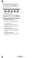
● Messages that can be assigned to [ON] keys
MIDI messages whose value switches to 0 or 127 can
be assigned to [ON] keys. For if you assign control
change #64 (Hold) to an [ON] key and make settings
so that the value switches to either 0 or 127, turning
the [ON] key on (lit) will transmit control change #64
with a value of 127 (Hold On), and turning it off (dark)
will transmit control change #64 with a value of 0
(Hold Off).
[Reference pages]
Details on the Bulk Dump page → P.31
Control change
number 64
(value=127)
Transmitted
ON
Version 2.0 Manual Supplement
ON
Control change
number 64
(value=0)
Transmitted
ON
13
AW4416 Version 2.0 Manual Supplement
In this state, you can press the [F1] key to access
the REMOTE screen.
You can also make settings so that a MIDI message
with a fixed value is transmitted only when the [ON]
key is turned on (lit). For example if you assign a program change #1 message, the corresponding program
change message will be transmitted each time you
turn the [ON] key on.
Program change
number 1
Program change
number 1
Transmitted
ON
ON
ON
Transmitted
ON
ON
■ Using the MIDI Remote function
with the default settings
The mixing layer that had been selected until
now will be cancelled, and a special mixing
layer called Remote A/Remote B will be in effect.
Remote A and Remote B are mixing layers that
let you use faders 1–16 and [ON] keys 1–16 to
transmit MIDI messages. Settings and operations
are performed in the following four pages.
With the default settings, MIDI messages are already
assigned to some of the faders and [ON] keys. Here’s
how to use the MIDI Remote function with the default
settings.
● Remote A 1-8
Tip!
Assign MIDI messages to Remote A faders 1–8/
[ON] keys 1–8
For the MIDI messages that are assigned by default to
the faders/[ON] keys by the MIDI Remote function,
refer to page 35.
1
● Remote A 9-16
Assign MIDI messages to Remote A faders 9–16/
[ON] keys 9–16
Connect the AW4416’s MIDI OUT/THRU
connector to the MIDI IN connector of the
external device.
● Remote B 1-8
Assign MIDI messages to Remote B faders 1–8/
[ON] keys 1–8
At this time, make sure that the MIDI Setup 2
page OUT/THRU switch is set to “OUT.”
2
● Remote B 9-16
Press the [MIDI] key.
Assign MIDI messages to Remote B faders 9–16/
[ON] keys 9–16
The MIDI screen will appear.
4
Press one of the [F1]–[F4] keys to select the
mixing layer that you want to operate.
If you press the [F1]/[F2] keys, you will be able to
operate Remote A. If you press the [F3]/[F4] keys,
you will be able to operate Remote B. (In the
example screen shown above, the Remote A 1-8
page is selected.)
5
3
Hold down the [SHIFT] key and press the
[F1] key to switch tabs.
In the various pages of the MIDI screen, the
lower part of the display will show the tabs as
long as you hold down the [SHIFT] key, as shown
below.
14
In the Remote A area in the right side of
the display, move the cursor to the DISABLE buttons for 1-8/9-16, and press the
[ENTER] key.
The button indication will change to “ENABLE,”
and the corresponding faders/[ON] keys can be
used for the MIDI Remote function.
If you set both the 1-8 and the 9-16 buttons to
“ENABLE,” remote operations can be performed
using all faders 1–16/[ON] keys 1–16 of the
same mixing layer.
Version 2.0 Manual Supplement
6
Operate faders 1–16/[ON] keys 1–16.
The MIDI messages assigned to the corresponding fader/[ON] key will be transmitted from the
MIDI OUT/THRU connector.
Tip!
• Even when the REMOTE screen is displayed, the
function of the faders and [ON] keys of the stereo
output channel will not change.
• The Remote A/Remote B fader positions and [ON]
key on/off status can be saved in a scene.
• Fader and [ON] key operations can also be recorded
in automix. By using automix to record operations
separately in each page, you can perform up to 32
channels of fader/[ON] key operations.
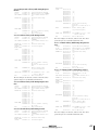
■ Assigning a MIDI message to a
fader
The MIDI Remote function lets you assign a MIDI
message of up to 16 bytes to each fader/each [ON]
key.
A message can be assigned in one of two ways. You
can input the desired message manually, one byte at a
time. Or you can capture a MIDI message received
from the MIDI IN connector/TO HOST connector/
option slot, and assign it either without change or
after editing it.
Here we will explain how to transmit a modulation
wheel message (control change #1) from a synthesizer
to the AW4416, and assign it to a desired fader.
1
• In the MIDI Setup 1 page, make sure that the ECHO
button in the CONTROL CHANGE area is turned
off. If the ECHO button is turned on, control
changes received from the external device will be
re-transmitted back to the external device, causing
malfunctions.
• In the MIDI Setup 2 page, make sure that the MIDI
OUT/THRU switch is set to OUT.
• The TX, RX, and OMNI buttons in the CONTROL
CHANGE area of the MIDI Setup 1 page will not
affect MIDI Remote operations.
Connect the MIDI OUT/THRU connector of
the AW4416 to the MIDI IN connector of
your synthesizer, and the MIDI IN connector of the AW4416 to the MIDI OUT connector of your synthesizer.
PROFESSIONAL AUDIO WORKSTATION
AW4416
MIDI IN
connector
MIDI OUT
connector
MIDI OUT/THRU
connector
MIDI IN
connector
2
3
4
Press the [MIDI] key.
Hold down the [SHIFT] key and press the
[F1] key to access the REMOTE screen.
Press one of the [F1]–[F4] keys to display
the fader/[ON] key to which you want to
assign a MIDI message.
The Remote A 1-8 page is selected in this example.
1
2
3
A MIDI message assigned to the [ON] key
B MIDI message assigned to the fader
C Currently selected channel number
5
Press the [SEL] key for the channel to
which you want to assign a MIDI message.
Areas 1 and 2 will show the MIDI messages
that are assigned to the fader and [ON] key of
that channel.
MIDI keyboard
Version 2.0 Manual Supplement
15
AW4416 Version 2.0 Manual Supplement
6
Move the cursor to the LEARN button
located above the message display area
(fader), and press the [ENTER] key.
The fader LEARN button will be turned on. While
this button is on, channel messages (note-on/off,
control change, program change, etc.) or system
exclusive messages received from an external
device will be captured automatically, and input
in the MIDI message display area of the fader.
8
Make sure that a MIDI message has been
input, and then move the cursor to the
fader LEARN button and press the [ENTER]
key to turn the LEARN button off.
You can turn this off directly by holding down the
[SHIFT] key and pressing the [F4] key.
9
Make sure that the Remote function of the
currently-displayed page is enabled
(ENABLE), and operate the fader to which
the MIDI message was assigned.
As you raise and lower the fader, control changes
will be transmitted with values varying in the
range of 0–127.
want to assign a name to the fader
10 Iftoyou
which the MIDI message was assigned,
Tip!
• If more than one MIDI message is received while
the LEARN button is on, the last-received MIDI message will be used.
• By holding down the [SHIFT] key and pressing the
[F4] key, you can directly switch the fader LEARN
button on/off.
7
move the cursor to the NAME EDIT button
for the fader, and press the [ENTER] key.
The NAME EDIT popup window will appear.
Operate the modulation wheel of your synthesizer.
The captured message (control change #1) will
be input into the fader message area. If a control
change is received, the byte corresponding to the
variable value of 0–127 (the third byte) will be
input as “FAD.” This indicates that the fader can
be used to vary the value in a range of 0–127.
the character palette to input a name,
11 Use
and move the cursor to the OK button and
press the [ENTER] key.
The name you input will be displayed below the
channel button located in the lower part of the
display.
Tip!
• When a MIDI message has been captured, a value of
“END” will automatically be input at the byte that
follows the last-received MIDI message.
• If you use the LEARN button to capture a channel
message, the MIDI channel of the captured message
will be used without change as the transmission
MIDI channel.
• If “FAD” is not specified within the MIDI message,
operating the fader will not transmit the MIDI message.
• If a MIDI message that is longer than 16 bytes is
received, only the first 16 bytes will be input. In this
case, the “END” value will not be input, meaning
that no MIDI message will be transmitted when you
operate the fader.
16
Tip!
• The edited content of the REMOTE screen is saved
as part of the song.
• If you want to return the settings of the displayed
page to the factory condition, hold down the
[SHIFT] key and press the [F5] key.
Version 2.0 Manual Supplement
■ Assigning a MIDI message to an
[ON] key
4
You can assign a desired MIDI message to an [ON]
key so that the message will be transmitted when you
press the key.
Press one of the [F1]–[F4] keys to display
the fader/[ON] key to which you want to
assign a MIDI message.
The Remote A 1-8 page is selected in this example.
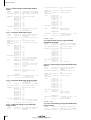
As an example, we will explain how you can use a
sustain pedal connected to your synthesizer to assign
a Hold-on message (control change #64 with a value
of 127) and Hold-off message (control change #64
with a value of 0) to [ON] key 1 of the Remote A 1-8
page.
1
Connect a sustain pedal to your synthesizer, the MIDI OUT/THRU connector of
the AW4416 to the MIDI IN connector of
your synthesizer, and the MIDI IN connector of the AW4416 to the MIDI OUT connector of your synthesizer.
• In the MIDI Setup 1 page, make sure that the ECHO
button in the CONTROL CHANGE area is turned
off. If the ECHO button is turned on, control
changes received from the external device will be
re-transmitted back to the external device, causing
malfunctions.
• In the MIDI Setup 2 page, make sure that the MIDI
OUT/THRU switch is set to OUT.
• The TX, RX, and OMNI buttons in the CONTROL
CHANGE area of the MIDI Setup 1 page will not
affect MIDI Remote operations.
5
Press the [SEL] key for the channel to
which you want to assign a MIDI message.
The display area will show the MIDI messages
that are currently assigned to the fader and [ON]
key of that channel.
Sustain pedal
PROFESSIONAL AUDIO WORKSTATION
AW4416
2
3
MIDI IN
connector
MIDI OUT
connector
MIDI OUT/THRU
connector
MIDI IN
connector
6
MIDI keyboard
Move the cursor to the LEARN button
located above the message display area
([ON] key), and press the [ENTER] key.
Press the [MIDI] key.
Hold down the [SHIFT] key and press the
[F1] key to access the REMOTE screen.
Tip!
• If more than one MIDI message is received while
the LEARN button is on, the last-received MIDI message will be used.
• By holding down the [SHIFT] key and pressing the
[F3] key, you can directly switch the [ON] key
LEARN button on/off.
Version 2.0 Manual Supplement
17
AW4416 Version 2.0 Manual Supplement
7
Operate the sustain pedal connected to
your synthesizer.
A control change #64 (Hold-on) message with a
value of 127 (hexadecimal 7F) will be input in
the [ON] key message area.
In this message, the first value in the boxes
extending toward the right (i.e., the first byte) is
the MIDI channel, the second is the control number, and the third byte is the actual value of the
message.
sure that the Remote function of the
10 Make
currently-displayed page is enabled
(ENABLE), and operate the [ON] key to
which the MIDI message was assigned.
When you press the [ON] key, the key LED will
light and a Hold-on message will be transmitted.
When you release the [ON] key, the key LED will
go dark and a Hold-off message will be transmitted.
Tip!
It is also possible to change the operation of the [ON]
key so that the on/off status is switched each time you
press the key. For details refer to the explanation of
the LATCH/UNLATCH button on page 34.
want to assign a name to the [ON]
11 Iftoyou
which the MIDI message was assigned,
8
Turn off the LEARN button, and take your
foot off of the sustain pedal.
move the cursor to the NAME EDIT button
for the [ON] key, and press the [ENTER]
key.
Tip!
The NAME EDIT popup window will appear.
If you take your foot off the sustain pedal before turning off the LEARN button, a control change #64 with
a value of 0 (hexadecimal 00) will be input in the
MIDI message display area. However even in this
case, the following steps will not be affected.
9
Move the cursor to the location of the third
byte, and use the [DATA/JOG] dial to
change the value to “SW.”
the character palette to input a name,
12 Use
and move the cursor to the OK button and
press the [ENTER] key.
The name you input will be displayed below the
channel button located in the lower part of the
display.
The byte whose value was set to “SW” will be
transmitted as 127 (hexadecimal 7F) when the
[ON] key is turned on (lit), and as 0 (hexadecimal 00) when the [ON] key is turned off (dark).
Tip!
The edited content of the REMOTE screen is saved as
part of the song.
Tip!
• It is also possible to input an entire MIDI message
manually in this way. In this case, be sure to specify
“END” at the end of the MIDI message.
• If you want a specific MIDI message to be transmitted each time you press [ON] (for example if you
have assigned a program change), it is not necessary
to input the “SW” value.
[Reference pages]
Details on the Remote A 1-8/Remote A 9-16/Remote
B 1-8/Remote B 9-16 pages → P.33
If you input a MIDI message manually, it is possible to
input an inappropriate or invalid message. If such a
MIDI message is transmitted to a connected external
device, the device may malfunction. Please use caution.
18
Version 2.0 Manual Supplement
Additional functionality for Automix
7
Due to the addition of the MIDI Remote function,
MIDI Remote operations can now be recorded/edited
in the automix.
In the AUTOMIX screen Main page, make
sure that the OVERWRITE area FADER button (if you want to record fader operations) or the CH ON button (if you want to
record [ON] key operations) is turned on.
When you defeat automix recording mode and
play back the song from the beginning, the MIDI
Remote operations you recorded will be reproduced.
Tip!
If necessary, you can switch REMOTE pages and use
another mixing layer (REMOTE A or REMOTE B) to
record additional MIDI Remote operations onto the
automix. By using this method, you can record up to
32 channels of fader/[ON] key operations.
■ Recording/playing back MIDI
Remote operations in automix
1
Stop the song.
■ Off-line editing of the recorded
automix
1
2
Access the AUTOMIX screen Event List
page.
In the OVERWRITE area, move the cursor to
the FADER button (if you want to edit fader
operations) or the CH ON button (if you
want to edit [ON] key operations), and
press the [ENTER] key.
Only the fader operations or [ON] key operations will be displayed in the event list. (However
at this stage, MIDI Remote events will not be displayed.)
2
3
Put the automix in record-ready mode.
Access the REMOTE screen, and press one
of the [F1]–[F4] keys to select the mixing
layer (Remote A or Remote B) that you
want to operate.
Remote A operations will be recorded if you
press the [F1]/[F2] keys, and Remote B operations will be recorded if you press the [F3]/[F4]
keys.
4
Make sure that the two buttons (1-8, 9-16)
of the REMOTE A area or REMOTE B area
are set to ENABLE.
If the 1-8 or 9-16 button reads DISABLE, the corresponding faders and [ON] keys will have no effect.
5
6
Begin playing back the song.
Use the [SEL] keys to select the fader or
[ON] key that you want to record, and
operate the fader/[ON] key.
While the REMOTE screen is displayed, operating the faders or [ON] keys will cause the operations to be recorded in automix as MIDI Remote
events.
Version 2.0 Manual Supplement
19
AW4416 Version 2.0 Manual Supplement
3
Move the cursor to the REMOTE button
located at the right of the event list, and
press the [ENTER] key.
The event list will display only the MIDI Remote
events (fader operations or [ON] key operations).
In this screen, each column of the event list displays the following information.
1
2
3
A TIME
This indicates the time at which the event is
recorded, in units of hours/minutes/seconds/milliseconds. (The minimum unit is 25 milliseconds.)
B EVENT (VALUE)
If the OVERWRITE area FADER button is on,
fader values will be displayed in hexadecimal
form. It OVERWRITE area CH ON button is on,
the on/off status of the [ON] keys will be displayed.
C CHANNEL
This shows the mixing layer (Remote A/Remote
B) for that event, and the channel (1–16) of the
fader/[ON] key.
4
Move the cursor to the TIME, EVENT
(VALUE), and CHANNEL columns of the
event that you want to edit, and turn the
[DATA/JOG] dial to edit the value.
[Reference pages]
For details on off-line automix editing → “Operation
Guide” P.225
For details on the AUTOMIX page Event List page →
“Reference Guide” P.122
20
Version 2.0 Manual Supplement
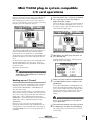
Mini YGDAI plug-in system compatible
I/O card operations
Plug-In 1 and Plug-In 2 pages have been added to display parameters for I/O cards compatible with the
Mini YGDAI plug-in system. To access the Plug-In 1
page, press the [AUX7] → [F5] key. To access the PlugIn 2 page, press the [AUX8] → [F5] key.
The content and operation of the Plug-In 1/Plug-In 2
pages will depend on the type of I/O card that is
installed. The screen shown here is of a prototype
Y56K DSP plug-in card manufactured by WAVES Corporation. For details refer to the manual for your I/O
card.
1
Press the [AUX7] key → [F5] key (or [AUX8]
key → [F5] key) to access the Plug-In 1
page (or Plug-In 2 page).
Access the Plug-In 1 page if you want to back up
the I/O card installed in option slot 1, or access
the Plug-In 2 page if you want to back up the I/O
card installed in option slot 2.
2
Hold down the [SHIFT] key and press the
[F1] (Backup) key.
A popup window will appear, allowing you to
back up the I/O card settings.
For details on the types of I/O cards compatible with
the Mini YGDAI plug-in system, please contact a
Yamaha information center, distributor, or the following Internet URL.
http://www.aw4416.com/
Tip!
In the Plug-In 1/Plug-In 2 pages you can use BACKUP
and RESTORE as additional functions. For details refer
to the sections below.
3
Backing up an I/O card
If one or two I/O cards compatible with the MiniYGDAI plug-in system are installed, you can use two
memory banks (MEM.BANK 1 / MEM.BANK 2) to
store I/O card settings.
Select either MEM.BANK 1 or MEM.BANK 2 to
choose the backup-destination memory bank (1
or 2). If the memory bank already contains data,
the bank name will be displayed. If it does not
contain data, the display will indicate “NO
DATA!”
Scene changes on the AW4416 are linked to changes
of the I/O card settings, and when you store the scene
(or save the song), settings of the I/O card installed in
option slot 1 will be automatically backed-up to
MEM.BANK 1, and settings of the I/O card installed in
option slot 2 will be automatically backed-up to
MEM.BANK 2.
However if necessary, you can also perform the
backup operation manually. This method allows the
settings of the I/O card in option slot 1 to be backed
up to MEM.BANK 2 (or vice versa). The procedure is
as follows.
Move the cursor to either the MEM.BANK
1 or MEM.BANK 2 button, and press the
[ENTER] key.
The bank name is assigned automatically according to
the type of I/O card installed. It is not possible for
you to edit this name.
4
To execute the backup, move the cursor to
the OK button and press the [ENTER] key.
The settings of the I/O card will be saved in the
current song.
Version 2.0 Manual Supplement
21
AW4416 Version 2.0 Manual Supplement
Restoring to an I/O card
When an AW4416 scene is recalled (or when a song
is loaded), the MEM.BANK 1 settings are automatically restored to the I/O card in option slot 1, and the
MEM.BANK 2 settings to the I/O card in option slot 2.
However if necessary, you can also perform the
restore operation manually. This method allows the
MEM.BANK 1 settings to be restored to the I/O card of
option slot 2 (or vice versa). The procedure is as follows.
1
At this time you must select a memory bank that contains data for an I/O card of the same type as the
restore-destination. If the I/O card is of a different
type, the Restore operation cannot be performed.
4
To execute the Restore operation, move
the cursor to the OK button and press the
[ENTER] key.
The saved settings will be loaded into the I/O
card.
Press the [AUX7] → [F5] key or the [AUX8]
key → [F5] key to access the Plug-In 1 page
or Plug-In 2 page.
Access the Plug-In 1 page if you want to restore
to the I/O card installed in option slot 1, or
access the Plug-In 2 page if you want to restore
to the I/O card installed in option slot 2.
2
Hold down the [SHIFT] key and press the
[F2] (Restore) key.
A popup window will appear, allowing you to
restore the I/O card settings.
3
Move the cursor to either the MEM.BANK
1 or MEM.BANK 2 button, and press the
[ENTER] key.
Select either MEM.BANK 1 or MEM.BANK 2 to
choose the restore-source memory bank (1 or 2).
If the memory bank already contains data, the
bank name will be displayed. If it does not contain data, the display will indicate “NO DATA!”
22
Version 2.0 Manual Supplement
Reference
This section explains all functions of the pages that were added in
AW4416 version 2.0.
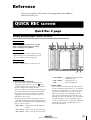
QUICK REC screen
Quick Rec 2 page
Visually patching input sources to tracks
Function
1
3
2
4
5
Individually patch 16 input sources to audio
tracks 1–16, and make settings for simultaneous recording in one operation.
Key operation
• [QUICK REC] key → [F2] (Quick Rec 2) key
• Repeatedly press the [QUICK REC] key until
the screen shown at the right appears.
Mouse operation
M button → QREC button → Quick Rec 2 tab
6 7
Screen functions
• DIN L/DIN R....... L/R channels of the DIGITAL
STEREO IN jack
D MIX.CH (Mixer channels)
• SMP 1–SMP 8...... Sampling pads 1–8
This column shows the type of input sources
assigned to input channels 1–16. The
(jack)
symbol displayed at the right of this area indicates
the direct output of each input channel.
When you move the cursor to the jack symbol and
press the [ENTER] key, the input channel for that
row will be selected for operations, and will be
highlighted. To cancel your selection, press the
[ENTER] key once again.
To change the input source assignment, move the
cursor to the numerical box for each input channel
and turn the [DATA/JOG] dial. The following input
sources can be assigned.
• MET..................... Internal metronome
E Patch cables
This area shows virtual patch cables that connect
the direct outputs of input channels 1–16 (MIX.CH
column) to recorder inputs 1–16 (REC.TR column).
To connect a patch cable, move the cursor to a
MIX.CH jack and press the [ENTER] key. Then
move the cursor to a REC.TR jack and press the
[ENTER] key. (You can make the same connection
by performing these steps in the opposite order.)
Use the CLEAR button (6) to defeat an individual
patch cable, or the ALL CLEAR button (5) to
defeat all patch cables.
• AD 1–AD 8..... Input signals from the INPUT 1–
8 jacks
• SL1-1–SL1-8 ... Inputs 1–8 of an I/O card (slot 1)
• SL2-1–SL2-8 ... Inputs 1–8 of an I/O card (slot 2)
Version 2.0 Manual Supplement
23
QUICK REC screen
• You may connect the direct output of a channel to
more than one track. However you cannot connect
more than one direct output to the same track.
• A maximum of 16 patch cables can be connected. If
you have connected all 16, you will not be able to
further modify the routing unless you disconnect one
of the cables.
F CURRENT/FLAT button
This button selects whether the corresponding
input channels will be reset to the default settings
when Quick Rec is executed. Move the cursor to
the button and press the [ENTER] key to switch
between the following two settings.
• If the CURRENT/FLAT button is set to FLAT, settings will be initialized for all input channels to
which a patch cable is connected.
• Input channels/tracks (monitor channels) to which
no patch cable is connected in the Quick Rec 2 page
will not be affected in any way.
• When you access the Quick Rec 2 page, the settings
you made most recently will be displayed. However
if you manually modified the input patching or
recorder input patching in another screen, it is possible that the patch cable display will not match the
actual signal flow.
● FLAT
When you execute Quick Rec, channel library 01
will be recalled to input channels to which an onscreen patch cable is connected, restoring the
parameters to their default settings.
● CURRENT
Input channel settings will not change when you
execute Quick Rec; only the patching will change.
G REC.TR (Recorder tracks)
This column shows the connection status of tracks
1–16 (Tr 1–16). The
(jack) symbol displayed at
the left of this area indicates the input for each
track.
When you move the cursor to a jack symbol and
press the [ENTER] key, that track will be highlighted, indicating that it is selected for operations.
You can cancel the selection by pressing the
[ENTER] key once again.
H ALL CLEAR button
This button clears all patch cable connections.
I CLEAR buttons
These buttons clear the patch cable connected to
the corresponding track.
J EXECUTE button
When you move the cursor to this button and
press the [ENTER] key, the patching settings specified in the Quick Rec 2 page will take effect.
At this time, the input channels/tracks to which
patch cables are connected will change as follows.
• The input patch and recorder input settings will
change according to the settings of the Quick
Rec 2 page.
• Assignments to the stereo bus will be forcibly
cancelled for all input channels to which a
patch cable is connected.
• Channel library number 01 will be recalled for
each monitor channel of a track to which a
patch cable is connected, resetting it to the
default state.
• All corresponding tracks will be set to recordready mode.
24
Version 2.0 Manual Supplement
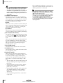
UTILITY screen
CTRL Key Asgn. page
Assign functions to the [CTRL] key + function keys
Function
1
Select the function that will be executed when you hold down the [CTRL]
key (right [SHIFT] key) and press an
[F1]–[F5] key.
Key operation
• [UTILITY] key → [F5] (CTRL
KeyAsgn.) key
• Repeatedly press the [UTILITY] key
until the screen shown at right
appears
2
3
4
5
Mouse operation
M button → UTIL button → CTRL
KeyAsgn. tab
Screen functions
A CTRL+F1–CTRL+F5
B Function list
This area displays the currently-assigned function
for each combination of CTRL key + [F1] key –
CTRL key +[F5] key. When you move the cursor to
the desired combination and press the [ENTER]
key, the graphic displaying the corresponding
[CTRL] key and [F1]–[F5] key combination will be
highlighted, selecting it as the destination for function assignment.
In this area you can specify the function to be
assigned to the key combination selected in 1.
The row enclosed by the dotted frame indicates
the currently selected function. The following
functions can be assigned.
Display
Function
NO ASSIGN
No function assigned
SHUT DOWN
Display the SONG screen/Shut Down screen (shortcut to shutdown) (*)
SONG SAVE
Display the SONG screen/Song List page, and move the cursor to the SAVE button
(shortcut to save the current song) (*)
CD LOAD
Close the tray of the CD-RW drive, and load the CD (*)
CD UNLOAD
Open the tray of the CD-RW drive (*)
AUTOMIX [Enable/Disable]
Turn automix on (Enable) or off (Disable) (*)
MTC SYNC [Master/Slave]
Switch the AW4416 between MTC master (Master) and MTC slave (Slave) (*)
REMOTE LAYER
Switch the mixing layer to Remote
TC DISPLAY
Switch the time counter display method between “SEC” → “TC” → “MES”
SCENE RECALL No##
Recall the desired scene number xx (use the [DATA/JOG] dial to select xx)
DELAY [ON/OFF]
Switch the delay on/off for the currently selected channel
EQ [ON/OFF]
Switch the EQ on/off for the currently selected channel
DYN [ON/OFF]
Switch the dynamics processor on/off for the selected channel
PEAK HOLD [ON/OFF]
Switch peak hold on/off
OSCILLATOR [ON/OFF]
Switch the test tone oscillator on/off
* unctions marked by an asterisk may not be executable depending on the operating state of the AW4416 (for example
when the transport is running). In this case, an error message will appear at the bottom of the display.
Version 2.0 Manual Supplement
25
UTILITY screen
C ASSIGN button
This button executes the function assignment.
When you move the cursor to this button and
press the [ENTER] key, a popup window will
appear, asking you for confirmation. Move the cursor to the OK button and press the [ENTER] key to
execute the assignment.
D SHIFT button
E CTRL button
Use these two buttons to select the function of the
[SHIFT] key at the right of the display. When the
SHIFT button is on, the key will function as a
[SHIFT] key, as usual. In this case the other items
in the CTRL KeyAsgn. page will be unavailable
(displayed in gray).
When the CTRL button is on, the [SHIFT] key at
the right of the display will function as a [CTRL]
key, and the other items in the CTRL KeyAsgn.
page will be valid.
Tip!
• While you hold down the [CTRL] key, the functions
currently assigned to the [F1]–[F5] keys will appear
at the bottom of the display.
• If the CD-RW drive is not selected in a screen such as
CD PLAY or MASTERING, the “CD LOAD” or “CD
UNLOAD” function assigned to the [CTRL] key +
function key will not be executed.
26
Version 2.0 Manual Supplement
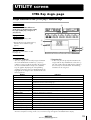
MIDI screen
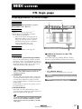
CTL Asgn. page
Assigning parameters to control changes
Function
1
2
Assign AW4416 internal parameters to control
change numbers (0–95, 102-119).
Key operation
• [MIDI] key → [F4] (CTL Asgn.) key (*1)
• Repeatedly press the [MIDI] key until the
screen shown at right appears.
*1. From version 2.0, the tabs displayed at the
bottom of the MIDI screen are divided into
two groups. If the tabs shown at right are
not displayed when you press the [MIDI]
key, press the [SHIFT] key + [F1]
(CHANGE TAB) key to switch tabs.
Mouse operations
M button → MIDI button → CTL Asgn. tab
4
■ Additional functions in the CTRL
Asgn. page
Screen functions
A CTL CHG No. (Control change number)
These are the control change numbers to which
parameters can be assigned. Move the cursor to
this column, and use the [DATA/JOG] dial to select
the control change number (0–95, 102–119) to
which you want to assign a parameter.
Control change numbers 96–118 are used for specific
purposes such as NRPN and RPN, and cannot be
assigned to parameters.
In the CTRL Asgn. page, holding down the [SHIFT]
key will assign the following function to the [F1] key.
• [F1] (CHANGE TAB) key
Switch between the following two sets of tabs.
B PARAMETER
This area shows the parameter that is assigned to
each control change number. In the left column,
select the desired parameter group, and in the
center and right columns, select the desired values
for that group.
For the parameters that can be assigned, refer to
the table on page 28.
C INITIALIZE button
This button resets the control change number
assignments to the default state. For the default settings, refer to the table on page 30.
Tip!
In order for control changes to actually be transmitted
and received, the CONTROL CHANGE area TX/RX
buttons must be turned on in the MIDI screen MIDI
Setup 1 page.
Version 2.0 Manual Supplement
27
MIDI screen
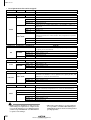
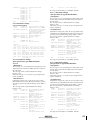
• List of parameters that can be assigned
Parameter 1
Parameter 2
Parameter 3
NO ASSIGN
Parameter 1
Parameter 2
Parameter 3
CHANNEL
MONI 1–16
Monitor channel 1–16
Return channel 1/2
Operate the stereo output channel fader or the AUX bus 1–8/bus 1–8
master level.
ST OUT
Stereo output channel
AUX 1–8
AUX bus 1–8
BUS 1–8
Bus 1–8
AUX 1 SEND
|
AUX 8 SEND
Parameter 2
Input channel 1–24
RETURN 1/2
MASTER
Parameter 1
Content
Operate the fader of the specified channel.
INPUT 1–24
FADER
Content
No parameter assigned
Operate the send level sent from the specified channel to AUX bus 1–8.
Parameter 2 specifies the send destination bus, and parameter 3 specifies
the channel.
INPUT 1–24
Input channel 1–24
MONI 1–16
Monitor channel 1–16
RETURN 1/2
Return channel 1/2
Parameter 3
Content
Control the on/off status of the channel [ON] key. Use parameters 2 and
3 to specify the desired channel.
ON
Parameter 1
INPUT 1–24
CHANNEL
Input channel 1–24
MONI 1–16
Monitor channel 1–16
RETURN 1/2
Return channel 1/2
MASTER
ST OUT
Stereo output channel
Parameter 2
Parameter 3
Content
Switch the phase (normal/reverse) of the specified channel.
PHASE
Parameter 1
INPUT 1–24
NOM/REV
Parameter 2
MONI 1–16
Monitor channel 1–16
RETURN 1/2
Return channel 1/2
Parameter 3
AUX 1 SEND
|
AUX 8 SEND
PRE/POST
Parameter 1
Parameter 2
Input channel 1–24
Content
Switch the pre-fader/post-fader settings of the signal that is sent from
each channel to AUX buses 1–8. Use parameter 2 to specify the bus, and
parameter 3 to select the desired channel.
INPUT 1–24
Input channel 1–24
MONI 1–16
Monitor channel 1–16
RETURN 1/2
Return channel 1/2
Parameter 3
Content
Control the delay of each channel. Use parameter 2 to select the parameter to be controlled, and parameter 3 to select the desired channel.
DELAY
ON/OFF
Delay on/off
TIME HIGH
Delay time ... (1)
TIME LOW
Delay time ... (2)
INPUT 1–24
Input channel 1–24
MONI 1–16
Monitor channel 1–16
RETURN 1/2
Return channel 1/2
• Parameters that are divided into (1) and (2) use two
control changes in conjunction. For example in order
to operate the dynamics processor HOLD parameter,
you must assign “REL/HOLD H” and “REL/HOLD L”
to separate control changes.
28
• When using control changes to operate parameters,
it is not possible to switch the HIGH band EQ and
LOW band EQ parameters between shelving and lowpass/high-pass filter.
Version 2.0 Manual Supplement
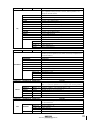
Parameter 1
Parameter 2
Parameter 3
Content
Control the channel EQ and attenuation. Use parameter 2 to select the
type of parameter that you want to control, and use parameter 3 to
specify the desired channel.
EQ
Parameter 1
ON/OFF
EQ on/off
Q LOW
Q of the LOW band EQ
F LOW
F (frequency) of the LOW band EQ
G LOW
G (gain) of the LOW band EQ
Q L-MID
Q of the L-MID band EQ
F L-MID
F (frequency) of the L-MID band EQ
G L-MID
G (gain) of the L-MID band EQ
Q H-MID
Q of the H-MID band EQ
F H-MID
F (frequency) of the H-MID band EQ
G H-MID
G (gain) of the H-MID band EQ
Q HIGH
Q of the HIGH band EQ
F HIGH
F (frequency) of the HIGH band EQ
G HIGH
G (gain) of the HIGH band EQ
ATT.
Attenuation
Parameter 2
INPUT 1–24
Input channel 1–24
MONI 1–16
Monitor channel 1–16
RETURN 1/2
Return channel 1/2
ST OUT
Stereo output channel
Parameter 3
Content
Control the dynamics processor of a channel. Parameter 2 selects the
dynamics processor parameter that will be controlled, and parameter 3
selects the channel.
DYNAMICS
ON/OFF
Dynamics processor on/off
THRESHOLD
THRESHOLD
ATTACK
ATTACK
GAIN/RANGE
GAIN or RANGE
RELEASE/HLD H
RELEASE ... (1) or HOLD H
RELEASE/HLD L
RELEASE ... (1) or HOLD L
RAT/DEC H
RATIO, or DECAY ... (1)
K/DEC L/WIDTH
RATIO, DELAY ...(2), or WIDTH
INPUT 1–24
Parameter 1
Parameter 2
Input channel 1–24
MONI 1–16
Monitor channel 1–16
RETURN 1/2
Return channel 1/2
ST OUT
Stereo output channel
Parameter 3
Content
Control the parameters of internal effect 1/2. Use parameter 2 to select
effect 1 or 2, and use parameter 3 to select the desired effect parameter.
EFFECT
Parameter 1
EFFECT1 H
PARAM 1–15
Parameter number 1–15 for internal effect 1 ... (1)
EFFECT1 L
PARAM 1–15
Parameter number 1–15 for internal effect 1 ... (2)
EFFECT1
MIX BAL
MIX BAL parameter of internal effect 1
EFFECT2 H
PARAM 1–15
Parameter number 1–15 for internal effect 2 ... (1)
EFFECT2 L
PARAM 1–15
Parameter number 1–15 for internal effect 2 ... (2)
EFFECT2
MIX BAL
MIX BAL parameter of internal effect 2
Parameter 2
Parameter 3
Content
Control the channel pan (or balance). Use parameters 2 and 3 to specify
the desired channel.
INPUT 1–24
PAN
CHANNEL
BALANCE
Input channel 1–24
MONI 1–16
Monitor channel 1–16
RETURN1 L/R
Return channel 1
RETURN2 L/R
Return channel 2
ST OUT
Balance of the stereo output channel
Version 2.0 Manual Supplement
29
MIDI screen
• Default parameters for each control change
number
CTL
CHG.
PARAMETER
119
NO ASSIGN
118
NO ASSIGN
117
FADER
AUX7 SEND
INPUT 16
102
FADER
AUX7 SEND
INPUT 1
95
NO ASSIGN
∫
∫
93
NO ASSIGN
92
PAN
BALANCE
ST OUT
91
PAN
CHANNEL
RETURN 2R
90
PAN
CHANNEL
RETURN 2L
89
PAN
CHANNEL
RETURN 1R
88
PAN
CHANNEL
RETURN 1L
87
PAN
CHANNEL
INPUT 24
64
PAN
CHANNEL
INPUT 1
63
ON
MASTER
ST OUT
62
ON
CHANNEL
RETURN 2
61
ON
CHANNEL
RETURN 1
60
ON
CHANNEL
INPUT 20
41
ON
CHANNEL
INPUT 1
40
FADER
MASTER
BUS 8
33
FADER
MASTER
BUS 1
32
NO ASSIGN
31
FADER
MASTER
AUX 8
24
FADER
MASTER
AUX 1
23
FADER
MASTER
ST OUT
22
FADER
CHANNEL
RETURN 2
21
FADER
CHANNEL
RETURN 1
20
FADER
CHANNEL
INPUT 20
1
FADER
CHANNEL
INPUT 1
0
NO ASSIGN
∫
∫
∫
∫
∫
30
Version 2.0 Manual Supplement
Bulk Dump page
Transmitting AW4416 internal settings via bulk dump
Function
Transmit the contents of various
AW4416 memories (scene memory,
libraries, automix, etc.) and MIDIrelated settings as bulk data from the
MIDI OUT/THRU connector (or TO
HOST connector/option slot).
1
Key operation
• [MIDI] key → [F5] (Bulk Dump) key (*1)
2
• Repeatedly press the [MIDI] key until
the screen shown at the right appears.
*1. From version 2.0, the tabs displayed
at the bottom of the MIDI screen are
divided into two groups. If the tabs
shown at right are not displayed
when you press the [MIDI] key,
press the [SHIFT] key + [F1]
(CHANGE TAB) key to switch tabs.
3
4
5
Mouse operations
M button → MIDI button → Bulk Dump tab
Screen functions
A CATEGORY
Select the type of information that will be transmitted as bulk data.
SETUP MEM.
PGM. TABLE
CTL. TABLE
If you select a SCENE MEM.–REMOTE category,
move the cursor to the area located at the right of
the corresponding button, and turn the [DATA/
JOG] dial to select the content within that category that will be transmitted. Each button corresponds to the following information.
Category
AW4416 settings other than the
following items
Settings of the MIDI screen PGM
ASGN. page
Settings of the MIDI screen CTL
ASGN. page
SCENE MEM.
The specified scene memory
PATCH LIBRARY
The specified patch library
CH LIBRARY
The specified channel library
EQ LIBRARY
The specified EQ library
DYN. LIBRARY
The specified dynamics library
EFF. LIBRARY
The specified effect library
AUTO MIX
The specified automix
MIDI REMOTE
Settings of the REMOTE screen
Values
—
—
—
01–96
EDIT BUFFER
ALL
01–20
ALL
02–64
ALL
41–128
ALL
41–128
ALL
42–128
ALL
1–16
BUFFER
ALL
REMOTE A–
REMOTE B
ALL
Scene number 1–96
Current scene (current mixer settings)
All scene memories + current scene
Library number 1–20
All patch libraries
Library number 2–64
All channel libraries
Library number 41–128
All EQ libraries
Library number 41–128
All dynamics libraries
Library number 42–128
All effect libraries
Memory number 1–16
Current automix
All automixes + current automix
Settings of the REMOTE A (REMOTE A 1-8/9-16
pages) or B (REMOTE B 1-8/9-16 pages)
Settings of all pages of the REMOTE screen
Version 2.0 Manual Supplement
31
MIDI screen
B ALL button
When you move the cursor to this button and
press the [ENTER] key, all buttons of area 1 will
be turned on. In addition, the “ALL” setting will be
selected as the value for SCENE MEM.–REMOTE.
C REQUEST button
When you move the cursor to this button and
press the [ENTER] key, a “bulk dump request”
message requesting the bulk dump data selected
in 1 will be transmitted from the MIDI OUT/
THRU connector (or TO HOST connector/option
slot).
This function is used when two AW4416 units are
connected by their respective MIDI IN/OUT connectors, and you want to copy scene memory or
library data from one AW4416 unit to the other.
Tip!
Depending on the external device to which the data is
being transmitted, an error may occur. If an error
occurs, try increasing the value of the INTERVAL 5
setting to leave a longer pause between the data
blocks that are transmitted. When transmitting data
between AW4416 units, you can leave this setting at
zero.
The time required for executing the bulk dump will
depend on the category that is selected and on the
content of the data. Particularly in the case of automix, a significantly long time may be required depending on the amount of data that is recorded.
■ Additional functions in the Bulk
Dump page
In the Bulk Dump page, holding down the [SHIFT]
key will assign the following function to the [F1] key.
PROFESSIONAL AUDIO WORKSTATION
AW4416
Bulk dump: reception on
MIDI OUT
MIDI IN
Bulk dump data
• [F1] (CHANGE TAB) key
Request message
MIDI IN
Switch between the following two sets of tabs.
MIDI OUT
PROFESSIONAL AUDIO WORKSTATION
AW4416
Bulk dump: reception on
D TRANSMIT button
When you move the cursor to this button and
press the [ENTER] key, the bulk data selected in 1
will be transmitted from the MIDI OUT/THRU
connector (or TO HOST connector/option slot).
Use this when you want to store bulk data on an
external device such as a MIDI sequencer or data
filer.
Before transmitting bulk data or a bulk dump request
message from a external device to the AW4416, you
must turn on bulk dump reception in the MIDI screen
MIDI Setup 1 page.
E INTERVAL
This adjusts the interval that will be left between
data blocks when bulk data is transmitted from the
AW4416. The default setting is 0 milliseconds, and
you can adjust the interval in 1 millisecond units
over a range of 0–300 milliseconds.
32
Version 2.0 Manual Supplement
Remote A 1-8/Remote A 9-16/
Remote B 1-8/Remote B 9-16 pages
Remotely controlling external MIDI devices
Function
2
3
4
5
Use faders 1–16/[ON] keys 1–16 to
transmit the desired MIDI messages and
remotely control external MIDI devices.
Key operation
1
• [MIDI] key → [F1] (Remote A 1-8) key
– [F4] (Remote B 9-16) key (*1)
• Repeatedly press the [MIDI] key until
the screen shown at the right appears.
*1. From version 2.0, the tabs displayed
at the bottom of the MIDI screen
are divided into two groups. If the
tabs shown at right are not displayed when you press the [MIDI]
key, press the [SHIFT] key + [F1]
(CHANGE TAB) key to switch tabs.
6
Mouse operations
M button → MIDI button → Remote A 18/Remote A 9-16/Remote B 1-8/Remote
B 9-16 tabs
Screen functions
A MIDI messages
The MIDI messages assigned to the fader and
[ON] key of the channel selected by the [SEL] key
are displayed here in hexadecimal form.
Move the cursor to each numerical box, and turn
the [DATA/JOG] dial to edit the value of each byte
(two-digital hexadecimal value). The following values can be selected.
• 00–FF (hexadecimal)
............... This is the MIDI message that
will actually be transmitted.
• END ............... This indicates the end of the
MIDI message. When you operate the fader or [ON] key, the
MIDI message from the beginning to immediately before END
will be transmitted.
• SW (only for [ON] key)
............... This indicates the on/off state of
the [ON] key. The byte whose
value is set to “SW” will be transmitted as a value of 7F (hexadecimal) when the [ON] key status
changes to On, and as a value of
00 (hexadecimal) when the key
changes to Off.
• FAD (only for fader)
............. This indicates the current position
of the fader. The byte whose value
is set to “FAD” will be transmitted
as a value of 00–7F (hexadecimal)
when you operate the fader.
Tip!
A MIDI message of up to 16 bytes (including “END”)
can be registered for a fader/[ON] key.
• When assigning a MIDI message, you must be sure to
add “END” at the end. If “END” is not specified, the
MIDI message will not be transmitted.
• If a MIDI message is assigned to a fader but “FAD” is
not specified within the MIDI message, operating the
fader will not transmit the MIDI message.
• When assigning a MIDI message to an [ON] key, you
can specify “SW” as one of the bytes as necessary. in
this case, the corresponding MIDI messages will be
transmitted when the [ON] key is turned on and
when it is turned off.
• If you do not specify “SW,” the assigned MIDI message will be transmitted only when the [ON] key is
turned on.
• If you input a MIDI message manually, it is possible
to input an inappropriate or invalid message. When
assigning MIDI messages, we recommend that you
use the LEARN button (4) whenever possible. (For
details on using the LEARN button to assign a MIDI
message, refer to page 15.)
Version 2.0 Manual Supplement
33
MIDI screen
B NAME EDIT button
D LEARN buttons
This button lets you edit the name (maximum of
eight characters) assigned to the fader/[ON] key.
When you move the cursor to this button and
press the [ENTER] key, a popup window will
appear, allowing you to input the desired name.
C LATCH/UNLATCH button
This button selects the operation when the [ON]
key is pressed. When you move the cursor to this
button and press the [ENTER] key, the button will
change between the following two settings.
● LATCH
Alternately switch on or off each time you press
the [ON] key.
● UNLATCH
Turn on when you press the [ON] key, and turn off
when you release the key.
• If “SW” is specified
LATCH
MIDI data transmitted
(SW=7F)
dark
lit
ON
ON
MIDI data transmitted
(SW=00)
dark
ON
ON
ON
When one of these buttons are on, channel messages
or system exclusive messages received at the MIDI IN
connector (or TO HOST connector/option slot) will be
input to the MIDI message area (1). By using this
function, a MIDI message received by the AW4416
can be assigned “as is” (or after being edited) to a
fader or [ON] key.
Tip!
• Normally you will turn on only one of the LEARN
buttons.
• When a channel message or system exclusive message is received while the LEARN button is on,
“END” will automatically be specified after the last
byte.
• If the fader LEARN button is on, and a control
change with a continuously changing value is
received, “FAD” will automatically be specified for
the variable byte.
If a system exclusive message longer than sixteen bytes
is received when the LEARN button is on, only the first
sixteen bytes will be input. In this case, the “END” will
not be input, meaning that no MIDI message will be
transmitted even when you operate the fader/[ON]
key.
E ENABLE/DISABLE buttons
These buttons select whether the Remote function
will be enabled (ENABLE) or disabled (DISABLE)
for the currently-displayed layer (Remote A or
Remote B). The enable/disable setting can be
made separately for each page.
UNLATCH
MIDI data transmitted
(SW=7F)
MIDI data transmitted
(SW=00)
dark
lit
dark
ON
ON
ON
• If “SW” is not specified
UNLATCH
MIDI data transmitted
dark
lit
dark
ON
ON
ON
When you operate an [ON] key or fader of an
enabled page, the MIDI message specified in 1
will be transmitted.
Tip!
• The [ON] key on/off status and fader position are
remembered for each layer.
• Operations of the faders and [ON] keys used for the
MIDI Remote function can also be recorded in automix. By using this method, you can simultaneously
use both layers Remote A and Remote B.
F 1–8/9–16 buttons
These indicate the channel (1–8 or 9–16) of the
[ON] keys and faders. The currently selected channel will be highlighted, and the MIDI messages
assigned to the [ON] key and fader of that channel
will be shown in the upper part of the display.
Below each button is shown the name of the [ON]
key (upper row) and fader (lower row) for the corresponding channel.
The channel can be selected in the following
ways.
• Press a [SEL] key
• Move the cursor to the button and press the
[ENTER] key
34
Version 2.0 Manual Supplement
• Default for MIDI remote page
Remote A 1–8
Channel
[ON] key
Name
Message
Fader
Name
Message
1
No assignment
CH1 VOL
Control change #7 (MIDI ch=1)
2
No assignment
CH2 VOL
Control change #7 (MIDI ch=2)
3
No assignment
CH3 VOL
Control change #7 (MIDI ch=3)
4
No assignment
CH4 VOL
Control change #7 (MIDI ch=4)
5
No assignment
CH5 VOL
Control change #7 (MIDI ch=5)
6
No assignment
CH6 VOL
Control change #7 (MIDI ch=6)
7
No assignment
CH7 VOL
Control change #7 (MIDI ch=7)
8
No assignment
CH8 VOL
Control change #7 (MIDI ch=8)
Remote A 9–16
Channel
[ON] key
Name
Message
Fader
Name
Message
9
No assignment
CH9 VOL
Control change #7 (MIDI ch=9)
10
No assignment
CH10 VOL
Control change #7 (MIDI ch=10)
11
No assignment
CH11 VOL
Control change #7 (MIDI ch=11)
12
No assignment
CH12 VOL
Control change #7 (MIDI ch=12)
13
No assignment
CH13 VOL
Control change #7 (MIDI ch=13)
14
No assignment
CH14 VOL
Control change #7 (MIDI ch=14)
15
No assignment
CH15 VOL
Control change #7 (MIDI ch=15)
16
No assignment
CH16 VOL
Control change #7 (MIDI ch=16)
Remote B 1–8
Channel
[ON] key
Name
Message
Fader
Name
Message
1
CH1 SUS
Control change #40 (MIDI ch=1)
CH1 VOL
Control change #7 (MIDI ch=1)
2
CH1 SOS
Control change #42 (MIDI ch=1)
CH1 PAN
Control change #10 (MIDI ch=1)
3
CH1 SOFT
Control change #43 (MIDI ch=1)
CH1 EXP
Control change #11 (MIDI ch=1)
No assignment
CH1 MOD
Control change #1 (MIDI ch=1)
Control change #41 (MIDI ch=1)
CH1 PORT
Control change #5 (MIDI ch=1)
6
No assignment
CH1 REV
Control change #91 (MIDI ch=1)
7
No assignment
CH1 CHO
Control change #93 (MIDI ch=1)
8
No assignment
CH1 VAR
Control change #94 (MIDI ch=1)
4
5
CH1 PORT
Remote B 9–16
Channel
[ON] key
Name
Message
Fader
Name
Message
9
PGM CHG1
Program change #1 (MIDI ch=1)
CTL CHG1
Control change #1 (MIDI ch=1)
10
PGM CHG2
Program change #2 (MIDI ch=1)
CTL CHG2
Control change #2 (MIDI ch=1)
11
PGM CHG3
Program change #3 (MIDI ch=1)
CTL CHG3
Control change #3 (MIDI ch=1)
12
PGM CHG4
Program change #4 (MIDI ch=1)
CTL CHG4
Control change #4 (MIDI ch=1)
13
PGM CHG5
Program change #5 (MIDI ch=1)
CTL CHG5
Control change #5 (MIDI ch=1)
14
PGM CHG6
Program change #6 (MIDI ch=1)
CTL CHG6
Control change #6 (MIDI ch=1)
15
PGM CHG7
Program change #7 (MIDI ch=1)
CTL CHG7
Control change #7 (MIDI ch=1)
16
PGM CHG8
Program change #8 (MIDI ch=1)
CTL CHG8
Control change #8 (MIDI ch=1)
Version 2.0 Manual Supplement
35
MIDI screen
■ Additional functions in the Remote
A 1-8 – Remote B 9-16 pages
In the Remote A 1-8 – Remote B 9-16 pages, holding
down the [SHIFT] key will assign the following functions to the [F1]–[F5] keys.
• [F1] (CHANGE TAB) key
Switch between the following two sets of tabs.
• [F2] (LATCH/UNLATCH) key
Switch between Latch and Unlatch as the operation when the [ON] key is pressed. This is the
same function as the LATCH/UNLATCH button
(3).
• [F3] (LEARN [ON]) key
A MIDI message received by the AW4416 will be
assigned to the [ON] key of the currently-displayed channel. This is the same function as the
LEARN button ([ON] key).
• [F4] (LEARN [FADER]) key
A MIDI message received by the AW4416 will be
assigned to the fader of the currently-displayed
channel. This is the same function as the LEARN
button (fader).
• [F5] (BANK INITIALIZE) key
All settings of the currently displayed page will be
reset to the default values. (For the default settings,
refer to page 35.)
36
Version 2.0 Manual Supplement
MIDI data format
1. Functions
1.7 MTC slave synchronization
1.1 MIDI setup
There are two types of serial connector: the MIDI connectors and the TO HOST connector. Each has the same
functionality, and you can select either of these to use,
depending on the type of device that will be connected.
Both types use the MIDI format for communication.
When using the TO HOST connector, you must select
one of the three transmission methods listed below.
Regardless of the type of connector you select, the MTC
OUT connector will output MTC.
Since the MTC transmitted from the MTC OUT connector is generated by hardware, its precision is very high.
The MIDI OUT/THRU connector can be used as either
THRU or OUT. If THRU is selected, the messages arriving at the MIDI IN connector will be re-transmitted without change from the MIDI OUT/THRU connector.
Name
Speed
Applicable to
---------------+-------------+-----------------------------------------PC1
31.25k
for NEC PC9800 series
PC2
38.4k
for DOS/V, NEC PC9800 series
Mac
31.25kf
or Macintosh (CLOCK=1MHz)
1.2 Scene change
The settings of the [Program Change Assign Table] specify
the scene that is recalled when a Program Change message is received.
The settings of the [Program Change Assign Table] specify
the program number that is transmitted when a scene is
recalled. If more than one program number has been
assigned to that scene memory number, the lowest-numbered program number will be transmitted. (If a memory
number is recalled for which there is setting in the [MIDI
Program Change Assign Table], the Parameter Change
(Function Call) listed later in this section will be transmitted.)
1.3 MMC control
These messages allow basic recorder operations such as
STOP/PLAY/REC/LOCATE.
If you select the MIDI SETUP menu item MMC MASTER,
MMC commands will be transmitted according to the
operation of the transport. If you select MMC SLAVE, the
internal recorder will operate according to the received
MMC commands.
1.4 Effect control
Depending on the type of effect, note-on/off messages
can be used for control.
These settings are made for the parameters of each effect.
1.5 MIDI Clock transmission
If the MIDI SETUP menu item [MTC SYNC] is set to
SLAVE, the internal recorder will operate in synchronization to MTC messages received from the MIDI IN or TO
HOST connector.
1.8 Realtime control of parameters
The internal parameters can be input or output in realtime using control changes or parameter changes.
1.9 Transmission of scene memories or library data
The bulk dump function can be used to send data to
another device, or copy settings from another device to
the AW4416.
1.10 MIDI Remote
MIDI data created by the user can be transmitted from
the AW4416 by operating its faders or ON keys.
2. AW4416 settings and operation
2.1 MIDI Setup
2.1.1 MIDI Channel
2.1.1.1 Transmit channel
This sets the MIDI channel that will normally be used.
However, transmission in response to a request will
occur on the Receive Channel, in order to specify the
desired that transmitted the request.
2.1.1.2 Receive channel
This sets the MIDI channel that will be used for reception. MIDI messages are normally received only if the
MIDI channel matches, but if OMNI is ON, they will be
received regardless of the channel.
2.1.2 ON/OFF
2.1.2.1 Program change
Enable/disable reception and transmission. If OMNI is
turned ON, reception will occur regardless of the MIDI
channel. If ECHO is ON, messages will be echoed
regardless of the channel.
2.1.2.2 Control change
Enable/disable reception and transmission. If OMNI is
turned ON, reception will occur regardless of the MIDI
channel. If ECHO is ON, messages will be echoed
regardless of the channel.
2.1.2.3 Parameter change
Enable/disable reception and transmission. If OMNI is
turned ON, reception will occur regardless of the MIDI
channel. If ECHO is ON, messages will be echoed
regardless of the channel.
If the MIDI SETUP menu item [MIDI CLK] is ON, MIDI
Clock messages will be transmitted during playback and
recording.
In MIDI Clock transmission mode, Song Position Pointer
and Start/Stop/Continue commands will also be issued,
and during playback or recording, MIDI Clock will be
transmitted according to the MIDI Tempo Map.
2.1.2.4 Bulk
1.6 MTC master
Select whether the MIDI IN/OUT connectors of the TO
HOST connector will be used for serial transmission.
(MTC output data will always be transmitted from the
MTC OUT connector.)
If the MIDI SETUP menu item [MTC] is ON, MTC will be
transmitted during playback and recording.
MTC will always be transmitted from the MTC OUT connector regardless of the [MTC] setting.
Enable/disable reception.
2.1.3 MMC Device ID
Specify the ID number used to transmit and receive
MMC commands.
2.1.4 MIDI/HOST
Version 2.0 Manual Supplement
37
MIDI data format
2.1.5 OUT/THRU
Select whether the MIDI OUT/THRU connector will
function as OUT or as THRU.
If THRU is selected, messages received at the MIDI IN
connector will be re-transmitted without change from the
MIDI OUT/THRU connector.
Regardless of the MIDI/HOST setting, the connector will
function as a THRU connector if the THRU setting is
selected. If you want to use the connector as MIDI OUT,
the MIDI/HOST setting must be OUT.
2.1.6 TO HOST
If the TO HOST connector is selected, choose one of
three settings depending on the type of computer that is
connected.
2.1.7 MIDI Clock ON/OFF
Specify whether MIDI Clock will be used.
If this is ON, MIDI Clock will be transmitted from the
connector selected by MIDI/HOST.
2.1.8 MTC ON/OFF
Select whether MTC will be used.
If this is ON, MTC will be transmitted from the connector
selected by MIDI/HOST.
Regardless of this setting, MTC will always be transmitted
from the MTC OUT connector.
2.2 Program change assign table
This table allows you to freely specify the correspondence between Program Change No. and Scene No.
This table is used for conversion for both transmission
and reception.
2.3 Control change assign table
This table allows you to freely specify the correspondence between Control Change No. and Parameter
name.
This table is used for conversion for both transmission
and reception.
3. MIDI format list
3.1 CHANNEL MESSAGE
command
rx/tx
function
-------------------------+-----+--------------------------------------8n NOTE OFF
rx
Control the internal effect
9n NOTE ON
rx
Control the internal effect
Bn CONTROL CHANGE rx/tx Edit parameters (use the Control
Change Assign Table)
Cn PROGRAM CHANGE rx/tx Switch scene memories (use the
Control Change Assign Table)
3.2 SYSTEM COMMON MESSAGE
command
rx/tx
function
-------------------------+-----+---------------------------------------
F1 MIDI TIME CODE rx/tx MTC transmission (when MTC
Master), MTC reception (when
MTC slave)
F2 SONG POSITION POINTER tx
SPP reception (when MIDI Clock
is used)
FE ACTIVE SENSING rx
FF RESET
rx
3.4 SYSTEM EXCLUSIVE MESSAGE
3.4.1 Real Time System Exclusive
3.4.1.1 MMC
command
rx/tx
function
-------------------------+-----+--------------------------------------01
02
03
04
05
06
07
0F
40
44
STOP
rx/tx
PLAY
rx
DEFERRED PLAY rx/tx
FAST FOWARD rx/tx
REWIND
rx/tx
RECORD STROBE rx
RECORD EXIT rx
RESET
rx/tx
WRITE
rx
LOCATE
rx/tx
F8 TIMING CLOCK tx
FA START
tx
FB CONTINUE
tx
FC STOP
tx
38
MIDI Clock transmission (when
MIDI Clock is used)
Start command transmission
(when MIDI Clock is used)
Continue command transmission
(when MIDI Clock is used)
Stop command transmit (when
MIDI Clock is used)
Transport stop
Transport play
Transport play
Transport fast-forward
Transport rewind
Transport punch-in record
Transport punch-out
MMC reset
Write data field
Transport locate
3.4.2 Bulk Dump & Request
data
name rx/tx function
-----+-------+-----------------------------------'M'
rx/tx Scene Memory & Request
'S'
rx/tx Setup Memory & Request
'R'
rx/tx Remote Memory & Request
'Q'
rx/tx Equalizer Library & Request
'Y'
rx/tx Dynamics Library & Request
'E'
rx/tx Effect Library & Request
'T'
rx/tx Patch Library & Request
'H'
rx/tx Channel Library & Request
'A'
rx/tx Automix Memory & Request
'P'
rx/tx Program Change Assign Table & Request
'C'
rx/tx Control Change Assign Table & Request
3.4.3 Parameter Change
Parameter
type rx/tx function
-----+-------+-----------------------------------0x00 rx/tx edit buffer (byte operation format)
0x01 rx
system memory (byte operation format)
0x02 rx/tx function call (mem/lib recall,mem/lib
store)
0x10 rx/tx edit buffer (7bit operation format)
0x40 rx/tx edit buffer (bit operation format)
0x41 rx
system memory (bit operation format)
0x43 rx
controller (key remote) (bit operation format)
4. MIDI format details
4.1 NOTE OFF (8n)
< Reception >
Received when [Rx CH] matches.
Used to control effects. Refer below for details.
STATUS
DATA
1000nnnn 8n
0nnnnnnn nn
0vvvvvvv vv
Note Off Message
Note No.
Velocity ( ignored)
4.2 NOTE ON (9n)
< Reception >
Received when [Rx CH] matches.
Used to control effects. Refer below for details.
Velocity of 0x00 is equivalent to Note-Off.
STATUS
DATA
3.3 SYSTEM REAL TIME MESSAGE
command
rx/tx
function
-------------------------+-----+---------------------------------------
Check MIDI cable connections
Clear running status
1001nnnn 9n
0nnnnnnn nn
0vvvvvvv vv
Note On Message
Note No.
Velocity (1-127:On, 0:off)
* Effect control by Note
1: Dynamic Flange/Dynamic Phase/Dynamic Filter
When the SOURCE parameter is set to MIDI, the note
velocity (both note-on and note-off) is used to control the
Modulation frequency width.
Version 2.0 Manual Supplement
4.3 CONTROL CHANGE (Bn)
< Reception >
< Reception >
This message is received when [Control Change RX] is
ON and the [Rx CH] matches. However if [OMNI] is
ON, this is received regardless of the channel.
This message is echoed if [Control Change ECHO] is
ON.
Parameters will be controlled according to the [Control
Change Assign Table] settings.
If a message is received while the [Control Change
Assign Table] is displayed, the cursor will move to that
control number.
< Transmission >
If [Control Change TX] is ON, this message is transmitted
on the [Tx CH] channel when a parameter specified in
the [Control Change Assign Table] is operated.
This message is echoed if [Control Change ECHO] is
ON.
STATUS
DATA
1011nnnn Bn
0ccccccc cc
0vvvvvvv vv
Control Change
Control No. (0-95, 102119)
Control Value (0-127)
The control value is converted into a parameter value
according to the following equation.
C = 128 (byte parameter)
16384 (word parameter)
S = total number of variable steps for the parameter
C/S = X remainder Y
INT((Y+1)/2) = Z
If (MIDI data - Z) < 0, then → param = 0
If ((MIDI data - Z)/X) > MAX, then → param = MAX
Otherwise → param = INT((MIDI DATA -Z)/X)
4.4 PROGRAM CHANGE (Cn)
< Reception >
This message is received if [Program Change RX] is ON
and [Rx CH] matches. However if [OMNI] is ON, this
message is received regardless of the channel.
This message is echoed if [Control Change ECHO] is
ON.
A scene memory will be recalled according to the [Program Change Assign Table] settings.
< Transmission >
If [Program Change TX] is ON, performing a Recall operation on the AW4416 will cause this message to be transmitted on the [Tx CH] according to the [Program Change
Assign Table] settings. If the recalled memory number
has been assigned to more than one program number,
the lowest-numbered program number will be transmitted.
(If a memory number not specified in the [Program
Change Assign Table] is recalled, the Parameter Change
(Function Call) described below will be transmitted.)
This message is echoed if [Control Change ECHO] is
ON.
STATUS
DATA
1100nnnn Cn
0nnnnnnn nn
Program Change
Program No. (0-127)
4.5 MIDI TIME CODE QUARTER FRAME(F1)
< Transmission >
When the recorder is in Play or Record status, Quarter
Frame messages are transmitted from the MIDI OUT connector (if [MTC] is ON) and from the MTC OUT connector.
This message is received if [MTC SYNC] is set to SLAVE.
Quarter Frame messages received in realtime are internally assembled into time code that controls the
recorder.
STATUS
DATA
11110001 F1
0nnndddd dd
Quarter Frame Message
nnn = message type (0-7)
dddd = data
4.6 SONG POTISION POINTER(F2)
< Transmission >
If [MIDI CLK] is ON, this message is transmitted when
the recorder Stops or Locates, to indicate the song position at which the next Start/Continue will begin.
STATUS
DATA
11110010 F2
Song Position Pointer
0ddddddd dd0 data( H) high 7 bits of 14
bits data
0ddddddd dd1 data( L) low 7 bits of 14
bits data
4.7 TIMING CLOCK(F8)
< Transmission >
If [MIDI CLK] is ON, this message is transmitted according to the MIDI Tempo Map from when the recorder
begins playing or recording, until it stops.
STATUS
11111000 F8
Timing Clock
4.8 START(FA)
< Transmission >
If [MIDI CLK] is ON, this message is transmitted when
the recorder begins playing or recording at the first measure.
STATUS
11111010 FA
Start
4.9 CONTINUE(FB)
< Transmission >
If [MIDI CLK] is ON, this message is transmitted when
the recorder begins playing or recording at a location
other than the first measure.
STATUS
11111011 FB
Continue
4.10 STOP(FC)
< Transmission >
If [MIDI CLK] is ON, this message is transmitted when
the recorder stops.
STATUS
11111100 FC
Stop
4.11 ACTIVE SENSING (FE)
< Reception >
Once this message is received, subsequent failure to
receive any message for a period of 300 ms will cause
Running Status to be cleared, and MIDI communications
to be initialized.
STATUS
11111110 FE
Active Sensing
4.12 RESET
< Reception >
When a Reset message is received, MIDI communications will be initialized by clearing Running Status etc.
STATUS
11111111 FF
Reset
4.13 EXCLUSIVE MESSAGE (F0-F7)
4.13.1 MMC
4.13.1.1 MMC STOP
< Transmission>
When the STOP key is pressed, this message is transmitted with a device number of 7F.
Version 2.0 Manual Supplement
39
MIDI data format
< Reception >
If the AW4416 is operating as an MMC Slave, the transport will stop when this message is received with a
matching device number or a device number of 7F.
STATUS
ID No.
Device ID
11110000 F0
01111111 7F
0ddddddd dd
Command
00000110 06
EOX
00000001 01
11110111 F7
System Exclusive Message
Real Time System Exclusive
Destination (00-7E, 7F:all
call)
Machine Control Command(mcc) sub-id
Stop(MCS)
End Of Exclusive
4.13.1.2 MMC PLAY
< Reception >
If the AW4416 is operating as an MMC Slave, the transport will begin playback when this message is received
with a matching device number or a device number of
7F.
STATUS
ID No.
Device ID
11110000 F0
01111111 7F
0ddddddd dd
Command
00000110 06
EOX
00000010 02
11110111 F7
System Exclusive Message
Real Time System Exclusive
Destination (00-7E, 7F:all
call)
Machine Control Command(mcc) sub-id
Play(MCS)
End Of Exclusive
4.13.1.3 MMC DEFERRED PLAY
< Transmission >
This message is transmitted with a device number of 7F
when the PLAY key is pressed.
< Reception >
If the AW4416 is operating as an MMC Slave, the transport will begin playback when this message is received
with a matching device number or a device number of 7F.
STATUS
ID No.
Device ID
11110000 F0
01111111 7F
0ddddddd dd
Command
00000110 06
EOX
00000011 03
11110111 F7
System Exclusive Message
Real Time System Exclusive
Destination (00-7E, 7F:all
call)
Machine Control Command(mcc) sub-id
Deferred play(MCS)
End Of Exclusive
4.13.1.4 MMC FAST FORWARD
< Transmission >
This message is transmitted with a device number of 7F
when the FF key is pressed or when the Shuttle is rotated
toward the right to enter Cue mode.
< Reception >
If the AW4416 is operating as an MMC Slave, the transport will begin fast-forward when this message is
received with a matching device number or a device
number of 7F.
STATUS
ID No.
Device ID
11110000 F0
01111111 7F
0ddddddd dd
Command
00000110 06
EOX
00000110 04
11110111 F7
System Exclusive Message
Real Time System Exclusive
Destination (00-7E, 7F:all
call)
Machine Control Command(mcc) sub-id
Fast Forward(MCS)
End Of Exclusive
4.13.1.5 MMC REWIND
< Transmission >
STATUS
ID No.
Device ID
11110000 F0
01111111 7F
0ddddddd dd
Command
00000110 06
EOX
00000101 05
11110111 F7
4.13.1.6 MMC RECORD STROBE
< Reception >
This message is received if the AW4416 is operating as
an MMC Slave and the device number matches or is 7F.
If the transport is stopped, then recording will begin. If
the transport is playing, then punch-in will occur.
STATUS
ID No.
Device ID
11110000 F0
01111111 7F
0ddddddd dd
Command
00000110 06
EOX
00000110 06
11110111 F7
This message is received if the AW4416 is operating as
an MMC Slave and the device number matches or is 7F.
If the transport is recording, then punch-out will occur.
STATUS
ID No.
Device ID
11110000 F0
01111111 7F
0ddddddd dd
Command
00000110 06
EOX
00000111 07
11110111 F7
System Exclusive Message
Real Time System Exclusive
Destination (00-7E, 7F:all
call)
Machine Control Command(mcc) sub-id
Record Exit
End Of Exclusive
4.13.1.8 MMC RESET
< Transmission >
This message is transmitted with a device number of 7F
when song loading is finished.
< Reception >
This message is received if the AW4416 is operating as
an MMC Slave and the device number matches or is 7F.
MMC-related internal settings will be reset to the poweron state.
STATUS
ID No.
Device ID
11110000 F0
01111111 7F
0ddddddd dd
Command
00000110 06
EOX
00001101 0D
11110111 F7
System Exclusive Message
Real Time System Exclusive
Destination (00-7E, 7F:all
call)
Machine Control Command(mcc) sub-id
Reset
End Of Exclusive
4.13.1.9 MMC WRITE
< Reception >
This message is received if the AW4416 is operating as
an MMC Slave and the device number matches or is 7F.
Data will be written into the specified information field.
STATUS
ID No.
Device ID
11110000 F0
01111111 7F
0ddddddd dd
Command
00000110 06
01000000 40
0ccccccc cc
0nnnnnnn nn
0ddddddd dd
< Reception >
40
System Exclusive Message
Real Time System Exclusive
Destination (00-7E, 7F:all
call)
Machine Control Command(mcc) sub-id
Record strobe
End Of Exclusive
4.13.1.7 MMC RECORD EXIT
< Reception >
This message is transmitted with a device number of 7F
when the REWIND key is pressed or when the Shuttle is
rotated toward the left to enter Review mode.
If the AW4416 is operating as an MMC Slave, the transport will begin rewind when this message is received with
a matching device number or a device number of 7F.
System Exclusive Message
Real Time System Exclusive
Destination (00-7E, 7F:all
call)
Machine Control Command(mcc) sub-id
Rewind(MCS)
End Of Exclusive
: :
0nnnnnnn nn
EOX
Version 2.0 Manual Supplement
11110111 F7
System Exclusive Message
Real Time System Exclusive
Destination (00-7E, 7F:all
call)
Machine Control Command(mcc) sub-id
Write
Byte Count
Writeable Information
Field name
Format defined by the
Information Filed name
More nn dd... pairs as
required..
End Of Exclusive
4.13.1.9.1 MMC INFORMATION FIELD - TRACK
RECORD READY
< Reception >
This message is received if the AW4416 is operating as
an MMC Slave and the device number matches. REC
SELECT will be switched on/off for the recorder tracks as
specified by the Standard Track Bitmap data.
01001111 4F
0nnnnnnn nn
0aaaaaaa aa
0bbbbbbb bb
0ccccccc cc
Track Record Ready (Information Field name)
Data Length (0:all track
off, 3:record track on)
1-2tr rec track On(Standard Track Bitmap)
3-9tr rec track On
10-16tr rec track On
4.13.1.10 MMC LOCATE(TARGET)
< Transmission >
This message is transmitted with a device number of 7F
when a locate-related key such as MARK SEARCH/IN/
OUT is pressed, a FF/REW/shuttle operation is performed, when the transport returns to the auto-punch
pre-roll point, or when repeating.
< Reception >
This message is received if the AW4416 is operating as
an MMC Slave and the device number matches. The
transport will locate to the time code position specified
within the command data.
STATUS
ID No.
Device ID
11110000 F0
01111111 7F
0ddddddd dd
Command
00000110 06
EOX
01000100
00000110
00000001
0hhhhhhh
0mmmmmmm
0sssssss
0fffffff
0sssssss
11110111
44
06
01
hh
mm
ss
ff
ss
F7
System Exclusive Message
Real Time System Exclusive
Destination (00-7E, 7F:all
call)
Machine Control Command(mcc) sub-id
Locate
byte count
"target" sub command
hour (Standard Time Code)
minute
second
frame
sub-frame
End Of Exclusive
4.13.2 Bulk Dump & Request
This message inputs/outputs the contents of various internal memories.
The unique header is used to distinguish whether the
data belongs to the AW4416.
The check sum is calculated by adding the bytes starting
after BYTE COUNT (LOW) and ending before CHECK
SUM, then inverting the bits and adding 1 (binary complement), and setting bit 7 to 0.
CHECK SUM = ( -sum) & 0x7F
< Reception >
This message is received if [Bulk RX] is on, and the [Rx
CH] matches the MIDI channel included in the Sub Status.
When a bulk dump is received, it is immediately written
into the specified memory.
When a bulk dump request is received, a bulk dump will
be transmitted immediately.
< Transmission >
Bulk Dump messages are transmitted on the [Tx CH] in
response to key operations in the [MIDI BULK] screen.
Bulk Dump messages are transmitted on the [Rx CH] in
response to Bulk Dump Request messages.
4.13.2.1 Scene Memory Bulk Dump Format
STATUS
ID No.
11110000 F0
01000011 43
SUB STATUS 0000nnnn 0n
FORMAT No. 01111110 7E
BYTE COUNT
(HIGH)
00011111 1F
BYTE COUNT
(LOW)
01111111 7F
01001100 4C
01001101 4D
00100000 20
00100000 20
00111000 38
01000011 42
00110011 39
00110110 38
DATA NAME 01001101 4D
0mmmmmmm mm
DATA
0ddddddd
CHECK SUM
:
0ddddddd
0eeeeeee
n=0-15(MIDI Channel No.116)
Universal Bulk Dump
4095bytes
'L'
'M'
' '
' '
'8'
'B'
'9'
'8'
'M'
m=0-96,127(Scene Memory
No.0-96, edit buffer)
Receive is effective No.196,127
ds1 Scene Memory(4095-10
bytes)
:
de1
ee1 ee1=(INVERT('L'+'M'+...
+ds1+...+de1)+1) AND 7Fh
BYTE COUNT
(HIGH)
00000111 07
998bytes
BYTE COUNT
(LOW)
01100110 66
DATA
0ddddddd ds2 Scene Memory(998 bytes)
: :
0ddddddd de2
CHECK SUM 0eeeeeee ee2 ee2=(INVERT(ds2+...+de2)
+1) AND 7Fh
EOX
11110111 F7
End Of Exclusive
The first 33 bytes are ID + Protect + Title, and are 7 bit.
The subsequent 2525 bytes are all divided into 4 bit units.
4.13.2.2 Scene Memory Bulk Dump Request Format
STATUS
11110000 F0
ID No.
01000011 43
SUB STATUS 0010nnnn 2n
FORMAT No. 01111110
01001100
01001101
00100000
00100000
00111000
01000011
00110011
00110110
DATA NAME 01001101
0mmmmmmm
EOX
7E
4C
4D
20
20
38
42
39
38
4D
mm
11110111 F7
System Exclusive Message
Manufacturer's ID (YAMAHA)
n=0-15(MIDI Channel No.116)
Universal Bulk Dump
'L'
'M'
' '
' '
'8'
'B'
'9'
'8'
'M'
m=0-97,127(Scene Memory
No.0-97, edit buffer)
End Of Exclusive
4.13.2.3 Setup Memory Bulk Dump Format
STATUS
ID No.
11110000 F0
01000011 43
SUB STATUS 0000nnnn 0n
FORMAT No. 01111110 7E
BYTE COUNT
(HIGH)
00000100 04
BYTE COUNT
(LOW)
00001010 0A
01001100 4C
01001101 4D
00100000 20
00100000 20
00111000 38
01000011 42
00110011 39
00110110 38
DATA NAME 01010011 53
00100000 20
DATA
System Exclusive Message
Manufacturer's ID No.
(YAMAHA)
Version 2.0 Manual Supplement
System Exclusive Message
Manufacturer's ID No.
(YAMAHA)
n=0-15(MIDI Channel No.116)
Universal Bulk Dump
522(512+10)bytes
'L'
'M'
' '
' '
'8'
'B'
'9'
'8'
'S'
' '
0ddddddd dsSetup Memory(256*2bytes)
: :
0ddddddd de
41
MIDI data format
CHECK SUM
0eeeeeee ee
EOX
11110111 F7
ee=(INVERT('L'+'M'+...+ds+
...+de)+1) AND 7Fh
End Of Exclusive
All data is divided into 4 bit units.
4.13.2.4 Setup Memory Bulk Dump Request Format
STATUS
11110000 F0
ID No.
01000011 43
SUB STATUS 0010nnnn 2n
FORMAT No. 01111110
01001100
01001101
00100000
00100000
00111000
01000011
00110011
00110110
DATA NAME 01010011
00100000
EOX
11110111
7E
4C
4D
20
20
38
42
39
38
53
20
F7
System Exclusive Message
Manufacturer's ID (YAMAHA)
n=0-15(MIDI Channel No.116)
Universal Bulk Dump
'L'
'M'
' '
' '
'8'
'B'
'9'
'8'
'S'
' '
End Of Exclusive
4.13.2.5 Remote Memory Bulk Dump Format
STATUS
ID No.
11110000 F0
01000011 43
SUB STATUS 0000nnnn 0n
FORMAT No. 01111110 7E
BYTE COUNT
(HIGH)
00010100 14
BYTE COUNT
(LOW)
00010010
01001100
01001101
00100000
00100000
00111000
01000011
00110011
00110110
DATA NAME 01010010
0bbbbbbb
DATA
0ddddddd
12
4C
4D
20
20
38
42
39
38
52
bb
ds
CHECK SUM
: :
0ddddddd de
0eeeeeee ee
EOX
11110111 F7
System Exclusive Message
Manufacturer's ID No.
(YAMAHA)
n=0-15(MIDI Channel No.116)
Universal Bulk Dump
2578(2568+10)bytes
'L'
'M'
' '
' '
'8'
'B'
'9'
'8'
'R'
b = 0-1(bank no.A-B)
Remote(Internal Parameter) Memory(1284*2bytes)
ee=(INVERT('L'+'M'+...+ds+
...+de)+1) AND 7Fh
End Of Exclusive
4.13.2.6 Remote Memory Bulk Dump Request Format
FORMAT No. 01111110
01001100
01001101
00100000
00100000
00111000
01000011
00110011
00110110
DATA NAME 01010010
0bbbbbbb
EOX
11110111
7E
4C
4D
20
20
38
42
39
38
52
bb
F7
System Exclusive Message
Manufacturer's ID (YAMAHA)
n=0-15(MIDI Channel No.116)
Universal Bulk Dump
'L'
'M'
' '
' '
'8'
'B'
'9'
'8'
'R'
b = 0-1(bank no.A-B)
End Of Exclusive
4.13.2.7 Equalizer Library Bulk Dump Format
STATUS
ID No.
11110000 F0
01000011 43
SUB STATUS 0000nnnn 0n
FORMAT No. 01111110 7E
BYTE COUNT
(HIGH)
00000000 00
42
3A
4C
4D
20
20
38
42
39
38
51
mm
DATA
0ddddddd ds
CHECK SUM
0ddddddd de
0eeeeeee ee
EOX
11110111 F7
System Exclusive Message
Manufacturer's ID No.
(YAMAHA)
n=0-15(MIDI Channel No.116)
Universal Bulk Dump
'L'
'M'
' '
' '
'8'
'B'
'9'
'8'
'Q'
m=0-127 (Equalizer Library
No.1-128)
Receive is effective
No.41-128
Equalizer Library Memory(16+(16*2)bytes
ee=(INVERT('L'+'M'+...+ds+
...+de)+1) AND 7Fh
End Of Exclusive
The first 16 bytes are the title, and are 7 bit. The subsequent 17 bytes are all divided into 4 bit units.
4.13.2.8 Equalizer Library Bulk Dump Request
Format
STATUS
11110000 F0
ID No.
01000011 43
SUB STATUS 0010nnnn 2n
FORMAT No. 01111110
01001100
01001101
00100000
00100000
00111000
01000011
00110011
00110110
DATA NAME 01010001
0mmmmmmm
EOX
7E
4C
4D
20
20
38
42
39
38
51
mm
11110111 F7
System Exclusive Message
Manufacturer's ID (YAMAHA)
n=0-15(MIDI Channel No.116)
Universal Bulk Dump
'L'
'M'
' '
' '
'8'
'B'
'9'
'8'
'Q'
m=0-127 (Equalizer Library
No.1-128)
End Of Exclusive
4.13.2.9 Dynamics Library Bulk Dump Format
STATUS
ID No.
11110000 F0
01000011 43
SUB STATUS 0000nnnn 0n
All data is divided into 4 bit units.
STATUS
11110000 F0
ID No.
01000011 43
SUB STATUS 0010nnnn 2n
BYTE COUNT
(LOW)
00111010
01001100
01001101
00100000
00100000
00111000
01000011
00110011
00110110
DATA NAME 01010001
0mmmmmmm
FORMAT No. 01111110 7E
BYTE COUNT
(HIGH)
00000000 00
BYTE COUNT
(LOW)
00101000 28
01001100 4C
01001101 4D
00100000 20
00100000 20
00111000 38
01000011 42
00110011 39
00110110 38
DATA NAM
01011001 59
0mmmmmmm mm
DATA
0ddddddd ds
CHECK SUM
: :
0ddddddd de
0eeeeeee ee
EOX
11110111 F7
System Exclusive Message
Manufacturer's ID No.
(YAMAHA)
n=0-15(MIDI Channel No.116)
Universal Bulk Dump
40(30+10)bytes
'L'
'M'
' '
' '
'8'
'B'
'9'
'8'
'Y'
m=0-127 (Dynamics Library
No.1-128)
Receive is effective
No.41-128
Dynamics Library Memory(16+(7*2)bytes)
ee=(INVERT('L'+'M'+...+ds+
...+de)+1) AND 7Fh
End Of Exclusive
The first 16 bytes are the title, and are 7 bit. The subsequent 7 bytes are all divided into 4 bit units.
58(48+10)bytes
Version 2.0 Manual Supplement
4.13.2.10 Dynamics Library Bulk Dump Request
Format
STATUS
11110000 F0
ID No.
01000011 43
SUB STATUS 0010nnnn 2n
FORMAT No. 01111110
01001100
01001101
00100000
00100000
00111000
01000011
00110011
00110110
DATA NAME 01011001
0mmmmmmm
EOX
7E
4C
4D
20
20
38
42
39
38
59
mm
11110111 F7
System Exclusive Message
Manufacturer's ID (YAMAHA)
n=0-15(MIDI Channel No.116)
Universal Bulk Dump
'L'
'M'
' '
' '
'8'
'B'
'9'
'8'
'Y'
m=0-127 (Dynamics Library
No.1-128)
End Of Exclusive
4.13.2.11 Effect Library Bulk Dump Format
STATUS
ID No.
11110000 F0
01000011 43
SUB STATUS 0000nnnn 0n
FORMAT No. 01111110 7E
BYTE COUNT
(HIGH)
00000000 00
BYTE COUNT
(LOW)
01110000 70
01001100 4C
01001101 4D
00100000 20
00100000 20
00111000 38
01000011 42
00110011 39
00110110 38
DATA NAME 01000101 45
0mmmmmmm mm
DATA
0ddddddd ds
CHECK SUM
: :
0ddddddd de
0eeeeeee ee
EOX
11110111 F7
System Exclusive Message
Manufacturer's ID No.
(YAMAHA)
n=0-15(MIDI Channel No.116)
Universal Bulk Dump
112(102+10)bytes
'L'
'M'
' '
' '
'8'
'B'
'9'
'8'
'E'
m=0-127 (Effect Library
No.1-128)
Receive is effective 42128
Effect Library Memory(16+(43*2)bytes)
ee=(INVERT('L'+'M'+...+ds+
...+de)+1) AND 7Fh
End Of Exclusive
The first 12 bytes are the title, and are 7 bit. The subsequent 41 bytes are all divided into 4 bit units.
4.13.2.12 Effect Library Bulk Dump Request Format
STATUS
11110000 F0
ID No.
01000011 43
SUB STATUS 0010nnnn 2n
FORMAT No. 01111110
01001100
01001101
00100000
00100000
00111000
01000011
00110011
00110110
DATA NAME 01000101
0mmmmmmm
EOX
7E
4C
4D
20
20
38
42
39
38
45
mm
11110111 F7
System Exclusive Message
Manufacturer's ID (YAMAHA)
n=0-15(MIDI Channel No.116)
Universal Bulk Dump
'L'
'M'
' '
' '
'8'
'B'
'9'
'8'
'E'
m=0-127 (Effect Library
No.1-128)
End Of Exclusive
4.13.2.13 Patch Library Bulk Dump Format
STATUS
ID No.
11110000 F0
01000011 43
SUB STATUS 0000nnnn 0n
FORMAT No. 01111110 7E
BYTE COUNT
(HIGH)
00000001 01
System Exclusive Message
Manufacturer's ID No.
(YAMAHA)
n=0-15(MIDI Channel No.116)
Universal Bulk Dump
BYTE COUNT
(LOW)
00011110
01001100
01001101
00100000
00100000
00111000
01000011
00110011
00110110
DATA NAME 01010100
0mmmmmmm
1E
4C
4D
20
20
38
42
39
38
54
mm
DATA
0ddddddd ds
CHECK SUM
: :
0ddddddd de
0eeeeeee ee
EOX
11110111 F7
'L'
'M'
' '
' '
'8'
'B'
'9'
'8'
'T'
m=0-20 (Patch Library
No.0-20)
Receive is effective No.120
Effect Library Memory(16+(66*2)bytes)
ee=(INVERT('L'+'M'+...+ds+
...+de)+1) AND 7Fh
End Of Exclusive
The first 12 bytes are the title, and are 7 bit. The subsequent 41 bytes are all divided into 4 bit units.
4.13.2.14 Patch Library Bulk Dump Request Format
STATUS
11110000 F0
ID No.
01000011 43
SUB STATUS 0010nnnn 2n
FORMAT No. 01111110
01001100
01001101
00100000
00100000
00111000
01000011
00110011
00110110
DATA NAME 01010100
0mmmmmmm
EOX
7E
4C
4D
20
20
38
42
39
38
54
mm
11110111 F7
System Exclusive Message
Manufacturer's ID (YAMAHA)
n=0-15(MIDI Channel No.116)
Universal Bulk Dump
'L'
'M'
' '
' '
'8'
'B'
'9'
'8'
'T'
m=0-20 (Patch Library
No.0-20)
End Of Exclusive
4.13.2.15 Channel Library Bulk Dump Format
STATUS
ID No.
11110000 F0
01000011 43
SUB STATUS 0000nnnn 0n
FORMAT No. 01111110 7E
BYTE COUNT
(HIGH)
00000000 00
BYTE COUNT
(LOW)
01110000 70
01001100 4C
01001101 4D
00100000 20
00100000 20
00111000 38
01000011 42
00110011 39
00110110 38
DATA NAME 01001000 48
0mmmmmmm mm
DATA
0ddddddd ds
CHECK SUM
: :
0ddddddd de
0eeeeeee ee
EOX
11110111 F7
System Exclusive Message
Manufacturer's ID No.
(YAMAHA)
n=0-15(MIDI Channel No.116)
Universal Bulk Dump
112(102+10)bytes
'L'
'M'
' '
' '
'8'
'B'
'9'
'8'
'H'
m=0-64 (Channel Library
No.0-64)
Receive is effective No.264
Effect Library Memory(16+(43*2)bytes)
ee=(INVERT('L'+'M'+...+ds+
...+de)+1) AND 7Fh
End Of Exclusive
The first 12 bytes are the title, and are 7 bit. The subsequent 41 bytes are all divided into 4 bit units.
158(148+10)bytes
Version 2.0 Manual Supplement
43
MIDI data format
4.13.2.16 Channel Library Bulk Dump Request
Format
STATUS
11110000 F0
ID No.
01000011 43
SUB STATUS 0010nnnn 2n
FORMAT No. 01111110
01001100
01001101
00100000
00100000
00111000
01000011
00110011
00110110
DATA NAME 01001000
0mmmmmmm
EOX
7E
4C
4D
20
20
38
42
39
38
48
mm
11110111 F7
System Exclusive Message
Manufacturer's ID (YAMAHA)
n=0-15(MIDI Channel No.116)
Universal Bulk Dump
'L'
'M'
' '
' '
'8'
'B'
'9'
'8'
'H'
m=0-64 (Channel Library
No.0-64)
End Of Exclusive
4.13.2.17 Automix Bulk Dump Format
STATUS
ID No.
11110000 F0
01000011 43
SUB STATUS 0000nnnn 0n
FORMAT No. 01111110 7E
BYTE COUNT
(HIGH)
00010000 10
BYTE COUNT
(LOW)
00011110 1E
01001100 4C
01001101 4D
00100000 20
00100000 20
00111000 38
01000011 42
00110011 39
00110110 38
DATA NAME 01000001 41
0mmmmmmm mm
DATA
0xxxxxxx xx
0xxxxxxx xx
0xxxxxxx xx
0xxxxxxx xx
0ttttttt tt
: :
0ttttttt tt
0ddddddd ds
CHECK SUM
: :
0ddddddd de
0eeeeeee ee
EOX
11110111 F7
System Exclusive Message
Manufacturer's ID No.
(YAMAHA)
n=0-15(MIDI Channel No.116)
Universal Bulk Dump
2078(1024*2+20+10)bytes
'L'
'M'
' '
' '
'8'
'B'
'9'
'8'
'A'
m=0-16 (Channel Library
No.1-16, current buffer)
block count (high)
block count (low) [0 (size-1)]
total block count (high)
total block count (low)
[size-1]
title1
title16
Automix Memory(1024*2
bytes)
ee=(INVERT('L'+'M'+...+ds+
...+de)+1) AND 7Fh
End Of Exclusive
4.13.2.18 Automix Bulk Dump Request Format
STATUS
ID No.
01000011 43
SUB STATUS 0010nnnn 2n
FORMAT No. 01111110
01001100
01001101
00100000
00100000
00111000
01000011
00110011
00110110
DATA NAME 01000001
0mmmmmmm
EOX
7E
4C
4D
20
20
38
42
39
38
41
mm
11110111 F7
11110000 F0System Exclusive Message
Manufacturer's ID (YAMAHA)
n=0-15(MIDI Channel No.116)
Universal Bulk Dump
'L'
'M'
' '
' '
'8'
'B'
'9'
'8'
'A'
m=0-16 (Channel Library
No.1-16, current buffer)
End Of Exclusive
4.13.2.19 Program Change Assign Table Bulk
Dump Format
STATUS
ID No.
44
11110000 F0
01000011 43
System Exclusive Message
Manufacturer's ID No.
(YAMAHA)
SUB STATUS 0000nnnn 0n
FORMAT No. 01111110 7E
BYTE COUNT
(HIGH)
00000001 01
BYTE COUNT
(LOW)
00001010 0A
01001100 4C
01001101 4D
00100000 20
00100000 20
00111000 38
01000011 42
00110011 39
00110110 38
DATA NAME 01010000 50
00100000 20
DATA
0ddddddd ds
CHECK SUM
: :
0ddddddd de
0eeeeeee ee
EOX
11110111 F7
n=0-15(MIDI Channel No.116)
Universal Bulk Dump
138(128+10)bytes
'L'
'M'
' '
' '
'8'
'B'
'9'
'8'
'P'
' '
Program Change
Table(128bytes)
ee=(INVERT('L'+'M'+...+ds+
...+de)+1) AND 7Fh
End Of Exclusive
All data is 7 bit.
4.13.2.20 Program Change Assign Table Bulk
Dump Request Format
STATUS
11110000 F0
ID No.
01000011 43
SUB STATUS 0010nnnn 2n
FORMAT No. 01111110
01001100
01001101
00100000
00100000
00111000
01000011
00110011
00110110
DATA NAME 01010000
00100000
EOX
11110111
7E
4C
4D
20
20
38
42
39
38
50
20
F7
System Exclusive Message
Manufacturer's ID (YAMAHA)
n=0-15(MIDI Channel No.116)
Universal Bulk Dump
'L'
'M'
' '
' '
'8'
'B'
'9'
'8'
'P'
' '
End Of Exclusive
4.13.2.21 Control Change Assign Table Bulk Dump
Format
STATUS
ID No.
11110000 F0
01000011 43
SUB STATUS 0000nnnn 0n
FORMAT No. 01111110 7E
BYTE COUNT
(HIGH)
00000010 02
BYTE COUNT
(LOW)
01100000 60
01001100 4C
01001101 4D
00100000 20
00100000 20
00111000 38
01000011 42
00110011 39
00110110 38
DATA NAME 01000011 43
00100000 20
DATA
0ddddddd ds
CHECK SUM
: :
0ddddddd de
0eeeeeee ee
EOX
11110111 F7
System Exclusive Message
Manufacturer's ID No.
(YAMAHA)
n=0-15(MIDI Channel No.116)
Universal Bulk Dump
352(342+10)bytes
'L'
'M'
' '
' '
'8'
'B'
'9'
'8'
'C'
' '
Control Change
Table(114*3bytes)
ee=(INVERT('L'+'M'+...+ds+
...+de)+1) AND 7Fh
End Of Exclusive
All data is 7 bit.
4.13.2.22 Control Change Assign Table Bulk Dump
Request Format
STATUS
11110000 F0
ID No.
01000011 43
SUB STATUS 0010nnnn 2n
Version 2.0 Manual Supplement
System Exclusive Message
Manufacturer's ID (YAMAHA)
n=0-15(MIDI Channel No.116)
FORMAT No. 01111110
01001100
01001101
00100000
00100000
00111000
01000011
00110011
00110110
DATA NAME 01000011
00100000
EOX
11110111
7E
4C
4D
20
20
38
42
39
38
43
20
F7
Universal Bulk Dump
'L'
'M'
' '
' '
'8'
'B'
'9'
'8'
'C'
' '
End Of Exclusive
4.13.3 Parameter Change
4.13.3.1 Basic format
STATUS
11110000 F0
ID No.
01000011 43
SUB STATUS 0pppnnnn pn
GROUP ID
MODEL ID
PARAM TYPE
DATA
EOX
00111110
00001000
0ttttttt
0ddddddd
:
0ddddddd
11110111
System Exclusive Message
Manufacturer's ID (YAMAHA)
p=mode (1:parameter change
or response for request
3:parameter request)
n=0-15(Rx Channel No.1-16)
3E
MODEL ID(Digital Mixer)
08
Device Code(AW4416)
tt
Parameter type
dd0 data 0
:
ddn data n
F7
End Of Exclusive
Parameter
type rx/tx function
------+------+----------------------------------0x00 rx/tx edit buffer (byte operation format)
0x01 rx/tx setup memory (byte operation format)
0x02 rx/tx function call (mem/lib recall,mem/lib
store)
0x10 rx/tx edit buffer (7bit operation format)
0x40 rx/tx edit buffer (bit operation format)
0x41 rx/tx setup memory (bit operation format)
0x43 rx/tx controller (key remote) (bit operation format)
4.13.3.2 Parameter Change
(byte operation for type 0x00:edit buffer)
4.13.3.2
< Reception >
This message is received if [Parameter Change RX] is ON
and the [Rx CH] matches the MIDI channel included in
the Sub Status.
This message will be echoed if [Parameter Change
ECHO] is ON.
When this message is received, the specified parameter
will be controlled.
< Transmission >
If [Parameter Change TX] is ON, this message will be
transmitted on the [Tx CH] MIDI channel when a parameter not specified in the [Control Change Assign Table] is
edited.
This message will be echoed if [Parameter Change
ECHO] is ON.
STATUS
ID No.
11110000 F0
01000011 43
SUB STATUS 0001nnnn 1n
GROUOP ID 00111110 3e
MODEL ID
00001000 08
PARAM TYPE 00000000 00
DATA
0aaaaaaa dd1
0aaaaaaa dd2
0000dddd dd3
0000dddd dd4
:
:
System Exclusive Message
Manufacturer's ID No.
(YAMAHA)
parameter change or
response n=0-15(MIDI
Channel No.1-16)
MODEL ID(digital mixer)
Device code (AW4416)
byte operation for edit
buffer (type)
address( H) high 7 bits of
14 bits address
address( L) low 7 bits of
14 bits address
data( H) high 4 bits of 8
bits data
data( L) low 4 bits of 8
bits data
continuous address datas
EOX
11110111 F7
End Of Exclusive
The range of valid addresses is 0x0000 - 0x0595.
4.13.3.3 Parameter Change
(7bit operation for type 0x10:edit buffer)
< Reception >
This message is received if [Parameter Change RX] is ON
and the [Rx CH] matches the MIDI channel included in
the Sub Status.
This message will be echoed if [Parameter Change
ECHO] is ON.
When this message is received, the specified parameter
will be controlled.
< Transmission >
If [Parameter Change TX] is ON, this message will be transmitted on the [Tx CH] MIDI channel when a parameter not
specified in the [Control Change Assign Table] is edited.
This message will be echoed if [Parameter Change
ECHO] is ON.
STATUS
ID No.
11110000 F0
01000011 43
System Exclusive Message
Manufacturer's ID No.
(YAMAHA)
SUB STATUS 0001nnnn 1n
parameter change n=015(MIDI Channel No.1-16)
GROUOP ID 00111110 3e
MODEL ID(digital mixer)
MODEL ID
00001000 08
Device code (AW4416)
PARAM TYPE 00010000 10
7bit operation for edit
buffer (type)
DATA
0aaaaaaa dd0 address( H) high 7 bits of
14 bits address
0aaaaaaa dd1 address( L) low 7 bits of
14 bits address
0ddddddd dd2 data 7bit
: :
EOX
11110111 F7
End Of Exclusive
The range of valid addresses is 0x0000 - 0x0595.
4.13.3.4 Parameter Change
(bit operation for type 0x40:edit buffer)
< Reception >
This message is received if [Parameter Change RX] is ON
and the [Rx CH] matches the MIDI channel included in
the Sub Status.
This message will be echoed if [Parameter Change
ECHO] is ON.
When this message is received, the specified parameter
will be controlled.
< Transmission >
If [Parameter Change TX] is ON, this message will be transmitted on the [Tx CH] MIDI channel when a parameter not
specified in the [Control Change Assign Table] is edited.
This message will be echoed if [Parameter Change
ECHO] is ON.
STATUS
ID No.
11110000 F0
01000011 43
System Exclusive Message
Manufacturer's ID No.
(YAMAHA)
SUB STATUS 0001nnnn 1n
parameter change n=015(MIDI Channel No.1-16)
GROUOP ID 00111110 3e
MODEL ID(digital mixer)
MODEL ID
00001000 08
Device code (AW4416)
PARAM TYPE 01000000 40
bit operation for edit
buffer (type)
DATA
0aaaaaaa dd0 address( H) high 7 bits of
14 bits address
0aaaaaaa dd1 address( L) low 7 bits of
14 bits address
0ddddddd dd2 data(bit0-2:change bit
no.0-7, bit3:0=reset
1=set)
: :
EOX
11110111 F7
End Of Exclusive
The range of valid addresses is 0x0000 - 0x0595.
Version 2.0 Manual Supplement
45
MIDI data format
4.13.3.5 Parameter Change
(byte operation for type 0x01:setup memory)
< Reception >
4.13.3.7 Parameter Value Request
(type 0x00:edit buffer, 0x01:setup memory)
< Reception >
This message is received if [Parameter Change RX] is ON
and the [Rx CH] matches the MIDI channel included in
the Sub Status.
This message will be echoed if [Parameter Change
ECHO] is ON.
When this message is received, the specified parameter
will be controlled.
This message is received if [Parameter Change RX] is ON
and the [Rx CH] matches the MIDI channel included in
the Sub Status.
This message will be echoed if [Parameter Change
ECHO] is ON and this AW4416 unit did not receive the
message.
When this message is received, the value of the specified
parameter will be transmitted as a Parameter Change
Message.
< Transmission >
This message will be echoed if [Parameter Change
ECHO] is ON.
STATUS
ID No.
11110000 F0
01000011 43
SUB STATUS 0001nnnn 1n
GROUOP ID 00111110 3e
MODEL ID
00001000 08
PARAM TYPE 00000001 01
DATA
0aaaaaaa dd0
0aaaaaaa dd1
0000dddd dd2
0000dddd dd3
EOX
: :
11110111 F7
System Exclusive Message
Manufacturer's ID No.
(YAMAHA)
parameter change or
response n=0-15(MIDI
Channel No.1-16)
MODEL ID(digital mixer)
Device code (AW4416)
byte operation for system
memory (type)
address( H) high 7 bits of
14 bits address
address( L) low 7 bits of
14 bits address
data( H) high 4 bits of 8
bits data
data( L) low 4 bits of 8
bits data
continuous address datas
End Of Exclusive
< Transmission >
This message will be echoed if [Parameter Change
ECHO] is ON and this AW4416 unit did not receive the
message.
STATUS
ID No.
11110000 F0
01000011 43
System Exclusive Message
Manufacturer's ID No.
(YAMAHA)
SUB STATUS 0011nnnn 3n
parameter request n=015(MIDI Channel No.1-16)
GROUOP ID 00111110 3e
MODEL ID(digital mixer)
MODEL ID
00001000 08
Device code (AW4416)
PARAM TYPE 00tttttt tt
00:edit buffer, 01:system
memory (type)
DATA
0aaaaaaa dd0 address( H) high 7 bits of
14 bits address
0aaaaaaa dd1 address( L) low 7 bits of
14 bits address
0ddddddd dd
count
EOX
11110111 F7
End Of Exclusive
The range of valid addresses is 0x0000 - 0x00ff.
The range of valid addresses is edit buffer 0x0000 0x0595 and setup memory 0x0000 - 0x00ff.
4.13.3.6 Parameter Change
(bit operation for type 0x41:setup memory)
< Reception >
4.13.3.8 Parameter Change
(type 0x02:function call)
< Reception >
This message is received if [Parameter Change RX] is ON
and the [Rx CH] matches the MIDI channel included in
the Sub Status.
This message will be echoed if [Parameter Change
ECHO] is ON.
When this message is received, the specified parameter
will be controlled.
This message is received if [Parameter Change RX] is ON
and the [Rx CH] matches the MIDI channel included in
the Sub Status.
This message will be echoed if [Parameter Change
ECHO] is ON.
When this message is received, the corresponding memory or library will be recalled or stored.
< Transmission >
< Transmission >
This message will be echoed if [Parameter Change
ECHO] is ON.
This message will be echoed if [Parameter Change
ECHO] is ON.
STATUS
ID No.
11110000 F0
01000011 43
System Exclusive Message
Manufacturer's ID No.
(YAMAHA)
SUB STATUS 0001nnnn 1n
parameter change or
response n=0-15(MIDI
Channel No.1-16)
GROUOP ID 00111110 3e
MODEL ID(digital mixer)
MODEL ID
00001000 08
Device code (AW4416)
PARAM TYPE 01000001 41
bit operation for system
memory (type)
DATA
0aaaaaaa dd0 address( H) high 7 bits of
14 bits address
0aaaaaaa dd1 address( L) low 7 bits of
14 bits address
0ddddddd dd2 data(bit0-2:change bit
no.0-7, bit3:0=reset
1=set)
: :
EOX
11110111 F7
End Of Exclusive
STATUS
ID No.
System Exclusive Message
Manufacturer's ID No.
(YAMAHA)
SUB STATUS 0001nnnn 1n
parameter change n=015(MIDI Channel No.1-16)
GROUOP ID 00111110 3e
MODEL ID(digital mixer)
MODEL ID
00001000 08
Device code (AW4416)
PARAM TYPE 00000010 02
function call
DATA
0ddddddd dd0 function
0ddddddd dd1 number
0ddddddd dd2 channel
EOX
11110111 F7
End Of Exclusive
The range of valid addresses is 0x0000 - 0x00ff.
46
Version 2.0 Manual Supplement
11110000 F0
01000011 43
function
number
channel
Tx/Rx
-----------------------+------------------------+----------------+--------0x00 scene recall
0-96(memory 0-96)
0x00
Tx* /Rx
0x01 eq lib recall
0-127(library 1-128)
0-26,32-47
Tx/Rx
0x02 dyn lib recall
0-127(library 1-128)
0-23,26,32-47
Tx/Rx
0x03 eff lib recall
0-127(library 1-128)
24,25
Tx/Rx
0x04 ch lib recall
0-64(library 0-64)
0-26,32-47
Tx/Rx
0x05 patch lib recall
0-20(library 0-20)
0
Tx/Rx
0x10 scene store
1-96(memory 1-96)
0x00
Rx only
0x11 eq lib store
40-127(library 41-128)
0-26,32-47
Rx only
0x12 dyn lib store
40-127(library 41-128)
0-23,26,32-47
Rx only
0x13 eff lib store
41-127(library 42-128)
24,25
Rx only
0x14 ch lib store
2-64(library 2-64)
0-26,32-47
Rx only
0x15 patch lib store
1-20(library 1-20)
0
Rx only
Channel
0-7(INPUT 1-8), 8-23(MONITOR 1-16), 24,25(RTN 1-2/EFF 1-2), 26(st mas)
* [0x00: scene recall] is transmitted only when you recall
a program that has not been assigned in the [Program
change table]. Normally a program change will be transmitted.
4.13.3.9 Parameter Change
(type 0x43:controller(key remote))
< Reception >
This message is received if [Parameter Change RX] is ON
and the [Rx CH] matches the MIDI channel included in
the Sub Status.
This message will be echoed if [Parameter Change
ECHO] is ON.
When this message is received, the same processing will
be performed as when the specified key (see table below)
is pressed (released)
< Transmission >
This message will be echoed if [Parameter Change
ECHO] is ON.
STATUS
ID No.
11110000 F0
01000011 43
SUB STATUS 0001nnnn 1n
GROUOP ID
MODEL ID
PARAM TYPE
DATA
EOX
00111110
00001000
01000011
00000000
0ddddddd
0000dddd
3e
08
43
00
dd
dd
: :
11110111 F7
System Exclusive Message
Manufacturer's ID No.
(YAMAHA)
parameter change n=015(MIDI Channel No.1-16)
MODEL ID(digital mixer)
Device code (AW4416)
controller
control no.(0:key remote)
No. 0-17(key 1-18)
data(bit0-2:change bit
no.0-7, bit3:0=reset
1=set)
End Of Exclusive
key no. rx/tx bit0
bit1
bit2
bit3
bit4
bit5
bit6
bit7
KEY
------+-----+-----+---------+---------+---------+---------+---------+---------+---------+--------key1
0
rx
SONG
VIEW
AUX5
SHIFT-L
BANK
SEL1
SEL9
ON1
key2
1
rx
ON9
ABS
CUE
SAFE
JOGON
NUM
REPEAT
REW
key3
2
rx
QUICK
PAN
AUX6
F1
PAD1
SEL2
SEL10
ON2
key4
3
rx
ON10
PEAK
REC1
REC9
UNDO
MARK<
A
key5
4
rx
MASTER
EQ
AUX7
F2
PAD2
SEL3
SEL11
ON3
key6
5
rx
ON11
TRACK
REC2
REC10
REDO
MARK>
B
FF
key7
6
rx
CD
DYN
AUX8
F3
PAD3
SEL4
SEL12
ON4
key8
7
rx
ON12
EDIT
REC3
REC11
UP
MARK
ROLL
key9
8
rx
SETUP
AUX1
HOME
F4
PAD4
SEL5
SEL13
ON5
key10
9
rx
ON13
A-MIX
REC4
REC12
DOWN
PUNCH
TOP
STOP
key11
10
rx
FILE
AUX2
1-16
F5
PAD5
SEL6
SEL14
ON6
key12
11
rx
ON14
SCENE
REC5
REC13
LEFT
IN
RTZ
key13
12
rx
UTILITY
AUX3
17-24
SHIFT-R
PAD6
SEL7
SEL15
ON7
key14
13
rx
ON15
STORE
REC6
REC14
RIGHT
OUT
END
PLAY
key15
14
rx
MIDI
AUX4
MONI
PAD7
SEL8
SEL16
ON8
key16
15
rx
ON16
SCENEREC7
REC15
ENTER
SET
CANCEL
key17
16
rx
HIGH
HI-MID
LOW-MID
LOW
PAD8
ASSIGN
SEL-ST
FOOT SW
key18
17
rx
ON-ST
SCENE+
REC8
REC16
SOLO
RECALL
ST
REC
You must transmit Reset (bit 3=0) after transmitting Set
(bit 3=1).
Version 2.0 Manual Supplement
47
YAMAHA CORPORATION
IP 48
Printed in Japan
Pro Audio & Digital Musical Instrument Division
P.O. Box 3, Hamamatsu, 430-8651, Japan