1
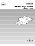
SX-15/12/8
USER'S MANUAL
This User's Manual is intended for SX-15, SX-12 and SX-8.
Thank you very much for purchasing the SX-15/12/8.
•
To ensure correct and safe usage with a full understanding of this product's performance, please be sure to read through this manual completely and store it in a safe
location.
•
Unauthorized copying or transferral, in whole or in part, of this manual is prohibited.
•
The contents of this operation manual and the specifications of this product are
subject to change without notice.
•
The operation manual and the product have been prepared and tested as much as
possible. If you find any misprint or error, please inform us.
•
Roland DG Corp. assumes no responsibility for any direct or indirect loss or damage
which may occur through use of this product, regardless of any failure to perform on
the part of this product.
•
Roland DG Corp. assumes no responsibility for any direct or indirect loss or damage
which may occur with respect to any article made using this product.
How to Read This Document
This document is organized as follows.
Part 1 Getting Started
This describes the preparations to make before you use the SX-15/12/8.
Read through this before you use the SX-15/12/8.
Part 2 Performing Cutting
This describes the basic steps for cutting.
Read through this when you're using the SX-15/12/8 for the first time.
Part 3 Mastering the SX
This describes features for further mastering use of the SX-15/12/8.
Part 4 User's Reference
This describes care, maintenance, and troubleshooting for the SX-15/12/8, and also contains the specifications of the SX-15/12/8.
The illustrations appearing in this manual depict the SX-15. The SX-12 and SX-8 may differ from the product shown.
For information about how to use the included Dr. STIKA PLUS program, see the PDF manual for Dr. STIKA PLUS on the Roland
Software Package CD-ROM, or refer to the program's help screens.
For information on how to operate Roland CutChoice™, see "Output from Roland CutChoice™" in this document or the Roland
CutChoice PDF manual on the Roland CutChoice CD-ROM.
Windows® is a registered trademark or trademark of Microsoft® Corporation in the United States and/or other countries.
TrueType is a trademark of Apple Computer, inc.
Adobe Illustrator is registerd trademark or trademark of Adobe Systems Incorporated in the U.S.A. and other countries.
Adobe and Acrobat are trademarks of Adobe Systems Incorporated.
CorelDRAW is registerd trademark of COREL Corporation.
CutChoice™ is a trademark of Roland DG corporaion.
Other company and product names appearing herein are trademarks or registered trademarks of thier respective holders.
Copyright © 2001 Roland DG Corporation
http://www.rolanddg.com/
1
Contents
To Ensure Safe Use .............................................................................................................................. 4
About the Labels Affixed to the Unit ............................................................................................. 6
Part 1 Introduction
1.1
1.2
Checking Accesories ................................................................................................................................. 1-1
Part Names ................................................................................................................................................ 1-2
1.3
Setting Up the SX ...................................................................................................................................... 1-3
Installation Space ................................................................................................................................... 1-3
1.4
Connecting the Cables ........................................................................................................................... 1-4
Installing and Setting Up the Software ....................................................................................................... 1-5
Operating Environment for Dr. STIKA PLUS .......................................................................................... 1-5
Installing and Setting Up Dr. STIKA PLUS and the Driver ...................................................................... 1-6
Part 2 Performing Cutting
2.1
Load the Material ....................................................................................................................................... 2-1
Using Roll Material ................................................................................................................................. 2-2
2.2
Creating Cutting Data ................................................................................................................................ 2-3
Starting the Software .............................................................................................................................. 2-3
Setting the Cutting Range and Tool Conditions ...................................................................................... 2-5
Manipulating Text and Shapes ............................................................................................................... 2-9
2.3
Starting Cutting ........................................................................................................................................ 2-12
If You Want to Stop Cutting Before It's Finished... ................................................................................ 2-13
2.4
Applying Cut Material ............................................................................................................................... 2-14
Part 3 Mastering the SX
3.1
Adjusting and Replacing the Blade ............................................................................................................ 3-1
Adjusting the Amount of Blade Extension .............................................................................................. 3-1
Verifying the Amount of Blade Extension ............................................................................................... 3-2
3.2
Changing the Blade ................................................................................................................................ 3-3
Setting the Tool Conditions ........................................................................................................................ 3-4
If You're Using Windows 95/98/Me ......................................................................................................... 3-4
If You're Using Windows NT 4.0 ............................................................................................................. 3-4
3.3
3.4
3.5
3.6
If You're Using Windows 2000 ................................................................................................................ 3-5
Cutting Range ............................................................................................................................................ 3-6
Changing the Loaded Material Width on the SX-15 .................................................................................. 3-7
Change the Loadable Material Width to 280 to 305 mm (11 to 12 in.) .................................................. 3-7
Returning the Loadable Material Width to 360 to 381 mm (14-1/8 to 15 in.) .......................................... 3-9
Correcting the Slant of Loaded Material .................................................................................................. 3-10
Importing Windows Bitmap Format .......................................................................................................... 3-11
Conditions for Data That Yields Attractive Cutting Results ................................................................... 3-11
Importing an Image .............................................................................................................................. 3-11
To Delete Unneeded Data .................................................................................................................... 3-12
3.7
2
Using a Scanner to Import an Object ................................................................................................... 3-13
Applying Large Material ........................................................................................................................... 3-14
Part 4 User's Reference
4.1
Care and Maintenance .............................................................................................................................. 4-1
Cleaning the Blade Tip ........................................................................................................................... 4-1
Cleaning the Blade Holder ..................................................................................................................... 4-1
Cleaning the Machine ............................................................................................................................. 4-1
Replacing the Blade Protector ................................................................................................................ 4-2
4.2
4.3
What to do if... ............................................................................................................................................ 4-3
Specifications ............................................................................................................................................. 4-6
Output from Roland CutChoice™ ......................................................................................................................... 4-7
3
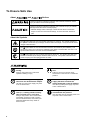
To Ensure Safe Use
About
and
Notices
Used for instructions intended to alert the user to the risk of death or severe
injury should the unit be used improperly.
Used for instructions intended to alert the user to the risk of injury or material
damage should the unit be used improperly.
* Material damage refers to damage or other adverse effects caused with
respect to the home and all its furnishings, as well to domestic animals or
pets.
About the Symbols
The
symbol alerts the user to important instructions or warnings. The specific meaning of
the symbol is determined by the design contained within the triangle. The symbol at left means
"danger of electrocution."
The
symbol alerts the user to items that must never be carried out (are forbidden). The
specific thing that must not be done is indicated by the design contained within the circle. The
symbol at left means the unit must never be disassembled.
The
symbol alerts the user to things that must be carried out. The specific thing that must
be done is indicated by the design contained within the circle. The symbol at left means the
power-cord plug must be unplugged from the outlet.
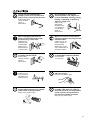
Do not disassemble, repair, or
modify.
Ground the unit with the ground
wire.
Doing so may lead to fire or abnormal
operation resulting in injury.
Failure to do so may result in risk of
electrocution in the event of a mechanical
problem.
Do not use with any power supply
other than the dedicated AC adapter.
Do not use with any electrical power
supply that does not meet the
ratings displayed on the AC adapter.
Use with any other power supply may lead
to fire or electrocution.
Do not use while in an abnormal
state (i.e., emitting smoke, burning
odor, unusual noise, or the like).
Doing so may result in fire or electrocution.
Immediately unplug the power-cord plug
from the electrical outlet, and contact your
authorized Roland DG Corp. dealer or
service center.
4
Use with any other power supply may lead
to fire or electrocution.
Use only with the power cord
included with this product.
Use with other than the included power cord
may lead to fire or electrocution.
Do not use with a damaged AC
adapter, power cord, or power-cord
plug, or with a loose electrical outlet.
Doing so may lead
to fire, electrical
shock, or
electrocution.
Do not damage or modify the
electrical power cord, subject it to
excessive bending, twisting, pulling,
binding, or pinching, or place any
object or weight on it.
Doing so may
damage the
electrical power
cord, leading to
fire, electrical
shock, or
electrocution.
When unplugging the electrical
power cord from the power outlet,
grasp the plug, not the cord.
When not in use for several hours,
unplug the power-cord plug from the
electrical outlet.
Unplugging by
pulling the cord
may damage it,
leading to fire,
electrical shock,
or electrocution.
Failure to do so may
result in danger of
electrical shock,
electrocution, or fire
due to deterioration of
electrical insulation.
Do not attempt to unplug the powercord plug with wet hands.
Do not allow liquids, metal objects
or flammables inside the machine.
Doing so may
result in electrical
shock or
electrocution.
Such materials
can cause fire.
Install on a stable surface.
Do not touch the tip of the blade
with your fingers.
Failure to do so
may result in the
unit tipping over,
leading to injury.
Do not allow children to operate
without adult supervision or operate
within reach of young children.
Doing so may result in injury.
Doing so may result in injury.
When using a commercially
available cutter knife for replacing
the blade protector, do not place the
hands anywhere along the path in
the direction of blade movement.
Doing so may result in injury.
5
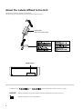
About the Labels Affixed to the Unit
These labels are affixed to the body of this product.
The following figure describes the location and content of these messages.
Rating label
Use a rated power supply.
Model name
In addition to the
NOTICE
and
: Indicates information to prevent machine breakdown or malfunction and ensure correct use.
: Indicates a handy tip or advice regarding use.
6
symbols, the symbols shown below are also used.
Part 1 Introduction
Part 1 Introduction
1.1
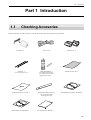
Checking Accesories
Check the following to make sure that you received all the items that were shipped along with the unit.
AC adapter : 1
Power cord : 1
Ferrite cores : 2
Material for test cuts : 1
Cable ties : 2
Blade holder/Blade : 1
* For securing ferrite cores.
*This blade holder and blade
are installed on the unit when
shipped from the factory.
Application tape for test cuts : 1
Replacement blade protector : 1
Roland Software Package CD-ROM: 1
*The configuration differs
according to the model.
Roland CutChoice CD-ROM : 1
SX-15/12/8 User's Manual : 1
1-1
Part 1 Introduction
1.2
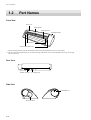
Part Names
Front View
Front cover
*Blade Holder
Blade protector
STANDBY LED
Pinch rollers
**Sheet adjustment levers
* There is packing material under the blade holder. Remove the packing material before you start cutting.
* * The SX-15 has sheet adjustment levers on the left and right, and the SX-12 has a sheet adjustment lever only on the right.
The SX-8 has none.
Rear View
Parallel connector AC adapter jack
Side View
STANDBY key
Sheet feed knob
1-2
Part 1 Introduction
1.3
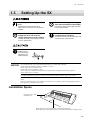
Setting Up the SX
Ground the unit with the ground
wire.
Do not use with any power supply
other than the dedicated AC adapter.
Failure to do so may result in risk of
electrocution in the event of a mechanical
problem.
Use with any other power supply may lead
to fire or electrocution.
Do not use with any electrical power
supply that does not meet the
ratings displayed on the AC adapter.
Use only with the power cord
included with this product.
Use with any other power supply may lead
to fire or electrocution.
Use with other than the included power cord
may lead to fire or electrocution.
Install on a stable surface.
Failure to do so
may result in the
unit tipping over,
leading to injury.
NOTICE
Never install this unit in any of the following situations, as it could result in damage:
• Places where the installation surface is unstable or not level.
• Places with excessive electrical noise.
• Places with excessive humidity or dust.
• Places with poor ventilation, because the SX-15/12/8 generates considerable heat during operation.
• Places with excessive vibration.
Use within a temperature range of 5 to 40°C (41 to 104°F) and within a humidity range of 35 to 80%.
Make sure the power to the computer and the SX-15/12/8 is switched off before attempting to connect the
cables.
Securely connect the power cord, computer I/O cable and so on so that they will not be unplugged. Otherwise,
faulty operation or breakdown may result.
Installation Space
Do not place any object
within the area.
50 mm
(2 in.)
When cutting starts, the material moves forward and backward.
Do not place any objects within the area in which the material moves during cutting.
1-3
Part 1 Introduction
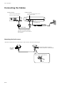
Connecting the Cables
Parallel connector
Parallel connector
Use the clips on either side to secure
the connector in place.
Use the screws on either side to
secure the connector in place.
AC adapter jack
Parallel Cable
The cable is available separately.
Be sure to use the correct cable for
the computer.
Attaching the ferrite cores
Attach the included ferrite core at the location on the connection cable shown in the figure.
20 to 30 mm
(13/16 to
1-3/16 in.)
20 to 30 mm (13/16 to 1-3/16 in.)
from the connector on the SX-15/12/8
*Secure in place with cable ties.
Cable tie
1-4
Part 1 Introduction
1.4
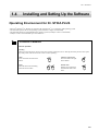
Installing and Setting Up the Software
Operating Environment for Dr. STIKA PLUS
- Microsoft® Windows® 95, Windows 98, Windows Me, Windows NT® 4.0, or Windows 2000 operating system
- The minimum required CPU for the operating system (Pentium® or higher recommended)
- The minimum amount of required RAM for the operating system (32 Mbytes or more recommended)
- 5 Mbytes or more of free hard disk space for installation
The Basics of Windows
Mouse operation
Pointing
When you move the mouse, the on-screen arrow (mouse pointer) also moves. Moving the mouse pointer to line up the
tip of the pointer with an item on the screen is called "pointing."
Click
Press and release the left mouse
button.
Click the right mouse
Press and release the right
mouse button.
Drag
Move the mouse while holding
down the mouse button.
Double click
Rapidly press and release
the left mouse button two
times.
1-5
Part 1 Introduction
Installing and Setting Up Dr. STIKA PLUS and the Driver
The explanations in this manual assume that you are already familiar with the basic operation of Windows.
*
If you are installing under Windows NT 4.0/2000, you need full access permissions for the printer settings.
Log on to Windows as a member of the “Administrators” or “Power Users” group.
For more information about groups, refer to the documentation for Windows.
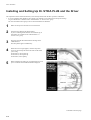
1
Make sure the power to the SX-15/12/8 is turned off.
2
Switch on the computer and start Windows.
If you are installing under Windows NT 4.0/2000, log on
to Windows as a member of the “Administrators” or
“Power Users” group.
3
Place the CD from the Roland Software Package in the
CD-ROM drive.
The Setup menu appears automatically.
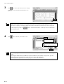
4
When the screen at right appears, click the drop-down
arrow for [Click here] and choose the name of the model
you're using.
For the SX-15, choose [SX-15].
For the SX-12, choose [SX-12].
For the SX-8, choose [SX-8].
5
Before installing and setting up, click [Read me] for each
piece of software and read the information displayed.
Continued on the next page
1-6
Part 1 Introduction
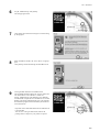
6
For [Dr. STIKA PLUS], click [Install].
The Setup program starts.
7
Click [Next], then follow the messages to continue setting
up the program.
8
When installation finishes, the screen shown at right appears.
Click [Finish], and finish installing the Dr.STIKA PLUS.
9
Viewing the PDF manual for Dr. STIKA PLUS.
The CD-ROM included with the SX-15/12/8 contains the
"Dr. STIKA PLUS User's Manual" as a PDF file.
For [Dr. STIKA PLUS], click [Read the User's Manual].
Acrobat Reader is required to view the PDF file. If Acrobat
Reader is not already installed and set up on your computer,
the installation program starts automatically. Follow the onscreen instructions.
* A printed version of the PDF manual for Dr. STIKA PLUS
is not included.
You can view it using Acrobat Reader, and use the
printing menu to output it to your printer as required.
1-7
Part 1 Introduction
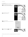
Next, install the driver.
This is required when sending data from a Windows-based program to the SX-15/12/8. Be sure to install it.
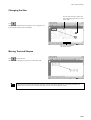
10
Make sure the model you’re using is selected.
Before installing and setting up, click [Read me] for each
piece of software and read the information displayed.
11
For [STIKA Driver], click [Install].
Installation of the driver starts.
12
The driver settings appear.
Check the values, click [Close], and finish installing the
driver.
13
At the Setup screen, click
to close the window.
Remove the CD-ROM from the CD-ROM drive.
*If the SX-15/12/8 does not operate when you send data from the program, take a look at "4.2 What to do if....".
1-8
Part 2 Performing Cutting
Part 2 Performing Cutting
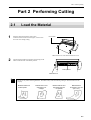
2.1
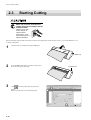
1
Load the Material
Place the material against the pinch rollers.
Load the material as shown in the figure, so that it does
not come loose during cutting.
Pinch rollers
Make sure the two sides of the material are even.
2
Turn the sheet feed knob to align the forward edge of the
material with the back of the blade protector.
Blade protector
Sheet feed knob
Do not use any of the following materials. The material may come loose during cutting or otherwise fail to be fed
properly.
Materials which has
curled upward
Material with a front
edge that is not
straight
Material with left and
right edges that are
not parallel
Material that is
longer than 1110 mm
(43-1/4 in.)
2-1
Part 2 Performing Cutting
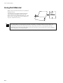
Using Roll Material
Material cannot be loaded on the SX-15/12/8 while still
attached to the roll.
Cut off from the roll a length of material equal to the
require length for cutting plus a margin of 30 mm.
The SX-15/12/8 can be loaded with material up to 1100
mm (43-1/4 in.) in length. However, the cutting area is
only up to 1,000 mm (39-5/16 in.).
Up to
(43-1/4 in.)
- Cut off the material at a right angle.If the end of the roll material is not straight, then the next time cutting is per
formed material feed may not be performed correctly, and the material may move at an angle and come loose.
- Depending on the composition of the material, it may not be possible to cut some fluorescent or reflective material,
even if the material is of a cuttable thickness.
2-2
Part 2 Performing Cutting
2.2
Creating Cutting Data
This section explains the basic operation of Dr. STIKA PLUS while making the sticker shown below. For information on editing and
operation to match the task at hand, please refer to "3 Mastering the SX" or the help for Dr. STIKA PLUS and the driver.
SALE
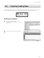
Starting the Software
1
Click [Start], and point to [Program].
Then point to [Roland Dr. STIKA PLUS] and click [Dr.
STIKA PLUS].
2
The opening screen appears and Dr. STIKA PLUS starts.
2-3
Part 2 Performing Cutting
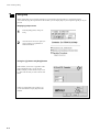
Using Help
When creating data, if you're unsure about how to proceed, follow the steps below to view the help screens.
Also, when carrying out an operation for the first time, you can display help on your computer to guide you as you
proceed.
Displaying help screens
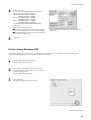
1
From the [Help] menu, click [Contents].
2
Click the mouse on text (or figures) in
green to display an explanation or
related information.
Using the [?] button and [Help] button
If the window you're in has a [?] button in the
upper right-hand corner, you can use this
button to display context-sensitive help. Click
[?], then click the item you wish to know more
about.
If there is a [Help] button in a window, you
can use this button to display help about the
window.
2-4
Part 2 Performing Cutting
Setting the Cutting Range and Tool Conditions
If You're Using Windows 95/98/Me
1
From the [File] menu, click [Print Setup].
The [Print Setup] dialog box appears.
2
For the SX-15, select [Roland SX-15]. For the SX-12,
select [Roland SX-12]. For the SX-8, select [Roland SX8]. Then click [Properties].
The [Properties] dialog box appears.
* The screen at right is shown when [Roland SX-15] has
been selected.
3
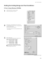
Set the cutting range.
If you are using the included material, make sure the
cutting range is set to the following values.
SX-15 : 340 mm (13.38 in.) (width)
270 mm (10.63 in.) (length)
SX-12 : 250 mm (9.84 in.) (width)
390 mm (15.35 in.) (length)
SX-8 : 160 mm (6.29 in.) (width)
270 mm (10.63 in.) (length)
* If you're using SX-12/8, width is a fixed value.
In [Cutting Area], for [Length], enter a value larger
than the length of the data to cut.
Continued on the next page
2-5
Part 2 Performing Cutting
4
Click [OK].
If You're Using Windows NT 4.0
*To change the settings for the various items, log on to Windows as "Administrator" or as a member of the "Power Users" group.
For more information about groups, refer to the documentation for Windows.
1
From the [File] menu, click [Print Setup].
The [Print Setup] dialog box appears.
2
For the SX-15, select [Roland SX-15]. For the SX-12,
select [Roland SX-12]. For the SX-8, select [Roland SX8]. Then click [Properties].
The [Properties] dialog box appears.
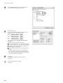
3
Under [Document Options], choose [MediaSizeSettings].
Click the [MediaSizeSettings] button.
The [MediaSizeSettings] dialog box appears.
2-6
Part 2 Performing Cutting
4
5
Set the cutting range.
If you are using the included material, make sure the
cutting range is set to the following values.
SX-15 : 340 mm (13.38 in.) (width)
270 mm (10.63 in.) (length)
SX-12 : 250 mm (9.84 in.) (width)
390 mm (15.35 in.) (length)
SX-8 : 160 mm (6.29 in.) (width)
270 mm (10.63 in.) (length)
* If you're using SX-12/8, width is a fixed value.
Click [OK].
The [Properties] dialog box appears.
If you want to change the size, click [Add New Media
Size], and at [Media Size], enter the value for [Length].
In [Cutting Area], for [Length], enter a value larger than
the length of the data to cut.
* This is the screen that appears when you click [Add New
Media Size].
Click [OK].
If You're Using Windows 2000
*To change the settings for the various items, log on to Windows as "Administrator" or as a member of the "Power Users" group.
For more information about groups, refer to the documentation for Windows.
1
From the [File] menu, click [Print Setup].
The [Print Setup] dialog box appears.
2
For the SX-15, select [Roland SX-15]. For the SX-12,
select [Roland SX-12]. For the SX-8, select [Roland SX8]. Then click [Properties].
The [Properties] dialog box appears.
3
Click [Advanced].
The [Advanced Options] dialog box appears.
Continued on the next page
2-7
Part 2 Performing Cutting
4
Choose [MediaSizeSettings], then click [Properties].
The [MediaSizeSetting] dialog box appears.
5
Set the cutting range.
If you are using the included material, make sure the
cutting range is set to the following values.
SX-15 : 340 mm (13.38 in.) (width)
270 mm (10.63 in.) (length)
SX-12 : 250 mm (9.84 in.) (width)
390 mm (15.35 in.) (length)
SX-8 : 160 mm (6.29 in.) (width)
270 mm (10.63 in.) (length)
* If you're using SX-12/8, width is a fixed value.
Click [OK].
The [Advanced Options] dialog box appears.
If you want to change the size, click [Add New Media
Size], and at [Media Size], enter the value for [Length].
In [Cutting Area], for [Length], enter a value larger
than the length of the data to cut.
Simply adding a media size does not make the driver
select it.
To select an added media size, then after adding the
size, click [OK] to close the [Print Setup] dialog box.
Then again display [Print Setup], go to the Media Size
List, and choose the size you added.
6
Click [OK].
The [Document Properties] dialog box appears.
Click [OK].
7
The [Print Setup] dialog box appears.
Click [OK].
2-8
Part 2 Performing Cutting
Manipulating Text and Shapes
Entering and Saving Text
The fonts that Dr. STIKA PLUS can use are limited to the TrueType fonts available for Windows. When selecting a font, non-TrueType
fonts are not displayed. Refer to the help screens for more information about using fonts.
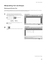
1
The white area of the screen is the cutting range. Any
portions that protrude beyond this area are not cut. Use
the zoom out function for Dr. STIKA PLUS to display the
entire cutting area on screen.
To zoom in or out, click
, then click on the
desired area of the screen.
Left click:
Right click:
Zoom in
Zoom out
For more information about the cutting range, see "3.3
Cutting Range."
2
Click
.
Click at the desired location, then enter "SALE" using the
keyboard.
Continued on the next page
2-9
Part 2 Performing Cutting
3
Click
. This encloses the "SALE" text in a rectangle
so that only the area of the sheet around what is cut is
peeled off.
Drag
-When you are cutting small text, you can make peeling easier by enclosing each single character in a square.
-All object overlapping is contextual, with the most recently created objects arranged on top. You can change the
context of objects by using the
buttons. For detailed information, see the help screens or PDF manual
for Dr.STIKA PLUS.
4
Click
and save the data you've made to a file.
1. Click
2. Select where the
file is to be saved.
3. Type in the file name. Files
created with Dr.STIKA PLUS
have ".stx" as the extension.
4. Click
-The cutting range you set with Dr. STIKA PLUS is not saved. When you reimport saved data, check the cutting
range.
-To change the default font for Dr. STIKA PLUS, start Dr. STIKA PLUS, and before you type in text, go to the
[Object] menu and use [Font Select] to select the font you want to make the default.
The changed font is applied only to text that you type in or select in Dr. STIKA PLUS.
2-10
Part 2 Performing Cutting
Changing the Size
You can freely enlarge or reduce the
size by dragging up or down or to the
left or right.
Click
.
Drag a text box with the mouse to change its size. Change the size
to fit inside the white portion of the display.
This lets you confirm the
size of the text box.
Moving Text and Shapes
Click
then click the text.
Move the text by dragging it up, down, or to the left or right.
When the [View] menu command [Snap To Grid] is selected, text strings automatically snap to the grid. When you
want to move a text string to a location off the grid, clear the selection for [Snap To Grid].
2-11
Part 2 Performing Cutting
2.3
Starting Cutting
When not in use for several hours,
unplug the power-cord plug from the
electrical outlet.
Failure to do so may
result in danger of
electrical shock,
electrocution, or fire
due to deterioration of
electrical insulation.
Before performing cutting, make sure the SX-15/12/8 has been prepared as described in the sections "2.1 Load the Material" to "2.2
Creating Cutting Data"
1
Close the front cover and press the [STANDBY] key.
STANDBY Key
2
The [STANDBY] LED lights up and the carriage moves
as shown in the figure, then stops.
3
Click
, then click [OK] in the dialog box that
appears.
Data is sent to the SX-15/12/8 and cutting starts.
2-12
STANDBY LED
Part 2 Performing Cutting
4
Press the [STANDBY] key to switch off the power.
Make sure the [STANDBY] LED is not lit up.
5
Rotate the material feed knob and remove the sheet.
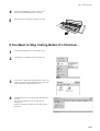
If You Want to Stop Cutting Before It's Finished...
1
Press the [STANDBY] key to switch off the power.
2
Click [Start]. Click [Settings], then click [Printers].
3
For the SX-15, double-click the [Roland SX-15] icon. For
the SX-12, double-click the [Roland SX-12] icon.For the
SX-8, double-click the [Roland SX-8] icon.
4
At the [Printers] menu, click [Purge Print Ducuments] or
[Cancel].
(If you’re using Windows 2000, click [Cancel All
Documents].)
Make sure the displayed data for the file being printed
disappears.
2-13
Part 2 Performing Cutting
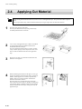
2.4
Applying Cut Material
When storing material that has been cut, be sure to cover it with application tape. This protects the material against
dust.
You can prevent the entry of dust inside the material by leaving an edge on the cut material at this time.
1
Peel off excess portions of the sheet.
You can peel detailed areas easily using commercially
available pointed tweezers or the like.
2
Cover evenly with application tape so that no air bubbles
are trapped between the tape and the material, then
transfer the material to the tape.
You can transfer the material easily by using a commercially available squeegee or the flat part of a ruler or the
like to rub the cut material from above the application
tape.
3
Wipe away any dust or oil from the location where the
material is to be applied.
4
When transferring the material to the object, air may get
between the material and the transfer surface, forming air
bubbles. If this happens, use a needle to puncture the
bubbles, then press out the trapped air and affix the
material to the transfer surface.
Place the entire piece of application tape against the
object, then press down evenly on the tape, working from
top to bottom. While constantly making sure the material
has been transferred to the object, slowly peel away the
application tape.
2-14
Part 3 Mastering the SX
Part 3 Mastering the SX
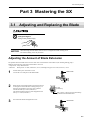
3.1 Adjusting and Replacing the Blade
Do not touch the tip of the blade
with your fingers.
Doing so may result in injury.
NOTICE
When mounting the blade holder, take care not to overtighten the blade retaining screw.
The cutter mounting screw may be broken.
Adjusting the Amount of Blade Extension
The optimal amount of blade extension is the same value as the thickness of the material (not including backing paper).
Material of the following composition and thickness can be cut.
- Composition Vinyl chloride sheets
- Thickness
Sheet portion :0.1 mm (0.00394 in.) or less, including base paper of 0.3 mm (0.0118 in.) or less
1
Switch off the power to the SX-15/12/8.
Loosen the screw and pull out the blade holder.
Blade Holder
Screw
2
3
Rotate the tip of the blade holder in the direction shown
in the figure to extend the blade. Turning the tip by an
amount corresponding to one large scale gradation
extends the blade by 0.1 mm (0.00394 in.).
The amount of blade extension when shipped from the
factory is 0.1 mm (0.00394 in.).
0.1 mm
(0.00394 in.)
Only a barely visible portion of the blade tip
protrudes from the blade holder.
Insert the blade holder and tighten the screw.
Blade holder
Screw
3-1
Part 3 Mastering the SX
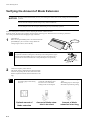
Verifying the Amount of Blade Extension
NOTICE
Be sure to load material before you carry out a cutting test. Failure to do so may damage the blade and blade
protector.
Do not move the carriage by hand. Doing so may result in breakdown.
Do not attempt to move the carriage by hand. Doing so may lead to faulty operation.
Perform a cutting test to check the results of adjusting the amount of blade extension.
With test cutting, the SX-15/12/8 actually cuts the material, allowing you to determine how well cutting is performed.
Test cutting is performed when changing the type of material.
1
Load material.
Make sure the [STANDBY] LED is lit and hold down the
[STANDBY] key for 2 seconds or longer. When the
carriage begins to move, release the key.
2 seconds or longer
The cutting test starts at the present location of the blade.
To perform continuous cutting tests, after the previous cutting finishes, again
hold down the [STANDBY] key for 2 seconds or longer. This cutting test is
performed at a location that does not overlap with the place cut previously.
1 cm
(3/8 in.)
2
Check the cut quality of the material.
The cutting quality is affected by the amount of blade
extension. Try peeling the cut sheet, and use the blade
holder to adjust the amount of blade extension accordingly.
-The blade leaves faint traces on
the backing paper when cutting
the cross.
Optimal amount of
blade extension
3-2
1 cm
(3/8 in.)
-The sticker cannot easily be
peeled off of the backing paper.
-Cut areas are not continuous.
-Cutting results are misaligned.
-The blade cuts into the backing
paper.
-The backing paper is cut through.
-The material peels during cutting.
Amount of blade extension is too short
Amount of blade
extension is too long
Part 3 Mastering the SX
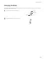
Changing the Blade
If the material is still not cut attractively even after adjusting the blade extension and performing test cutting several times, the blade tip
may be broken. Replace it with a new blade.
1
Press the push-pin and remove the old blade.
Push pin
Blade holder
Blade
2
Insert the new blade firmly until it clicks into place.
3-3
Part 3 Mastering the SX
3.2 Setting the Tool Conditions
If You're Using Windows 95/98/Me
1
Start Dr. STIKA PLUS and display the [Properties] dialog
box.
For information on how to display the [Properties] dialog
box, refer to "2.2 Setting the Cutting Range."
2
Click the [Tools] tab.
The [Tools] tab appears.
When using the included blade and material, there is no
need to change the tool conditions. Make sure [Machine
Setting] is displayed and click [OK].
The [Print Setup] dialog box appears.
Click [OK].
If You're Using Windows NT 4.0
1
Start Dr. STIKA PLUS and display the [Properties] dialog
box.
For information on how to display the [Properties] dialog
box, refer to "2.2 Setting the Cutting Range."
2
When using the included blade and material, there is no
need to change the tool conditions. Click [Selected Tool],
and make sure it is set to [Machine Setting].
The [Print Setup] dialog box appears.
Click [OK].
3-4
Part 3 Mastering the SX
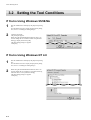
If You're Using Windows 2000
1
Start Dr. STIKA PLUS and display the [Properties] dialog
box.
For information on how to display the [Properties] dialog
box, refer to "2.2 Setting the Cutting Range."
2
When using the included blade and material, there is no
need to change the tool conditions. Click [Selected Tool],
and make sure it is set to [Machine Setting].
Click [OK].
The [Document Properties] dialog box appears.
Click [OK].
The [Print Setup] dialog box appears.
Click [OK].
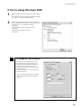
To Change the Tool Conditions
To change the tool conditions and use something other than the included material, go to
[Settings] and change [Machine Settings] to
[1] or [2], [Tool 1], [Tool 2], and so on.
Enter the required values for [Speed], [Offset],
and [Compensate].
For details about these items, refer to the help
screens for the driver.
* The screen shown is for Windows 95/98/Me.
The screens for Windows NT 4.0/2000 are
different.
3-5
Part 3 Mastering the SX
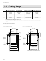
3.3 Cutting Range
Cutting range (width)
340 mm
(13-3/8 in.)
250 mm
(9-13/16 in.)
250 mm
(9-13/16 in.)
160 mm
(6-1/4 in.)
SX-15
SX-12
SX-8
Cutting range (length)
1000 mm
(39-5/16 in.)
1000 mm
(39-5/16 in.)
1000 mm
(39-5/16 in.)
1000 mm
(39-5/16 in.)
Loadable material (width)
360 to 381 mm
(14-1/8 to 15 in.)
280 to 305 mm
(11 to 12 in.)
280 to 305 mm
(11 to 12 in.)
200 to 215 mm
(7-13/16 to 8-7/16 in.)
Loadable material (length)
1100 mm
(43-1/4 in.)
1100 mm
(43-1/4 in.)
1100 mm
(43-1/4 in.)
1100 mm
(43-1/4 in.)
• The sheet behind the cutter holder cannot be cut.
• The front and the left and right side of the material are necessary margins to allow feed of the material by the pinch
rollers.
The cutting range is inside the dotted box.
If You're Using the SX-15
If You're Using the SX-12/8
Pinch rollers
Pinch rollers
Blade holder
Blade holder
Blade protector
Blade protector
Maximum
1000 mm
(39-5/16 in.)
Maximum
1000 mm
(39-5/16 in.)
Material
Margines
30 mm
(1-3/16 in.)
Cutting range (width)
250 mm (9-13/16 in.)
Cutting range (width)
340 mm (13-3/8 in.)
Loadable material (width)
280 to 305 mm (11 to 12 in.)
Loadable material (width)
360 to 381 mm (14-1/8 to 15 in.)
3-6
Material
Margines
30 mm
(1-3/16 in.)
Cutting range (width)
SX-12: 250 mm (9-13/16 in.)
SX-8 : 160 mm (6-1/4 in.)
Loadable material (width)
SX-12: 280 to 305 mm (11 to 12 in.)
SX-8 : 200 to 215 mm (7-13/16 to 8-7/16 in.)
Part 3 Mastering the SX
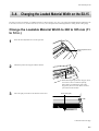
3.4 Changing the Loaded Material Width on the SX-15
The SX-15 can also use material of a width for the SX-12 (280 to 305 mm (11 to 12 in.)) To change the loadable material width from 360
to 381 mm (14-1/8 to 15 n.) to 280 to 305 mm (11 to 12 in.), move the pinch-roller and change the driver setting for the cutting range.
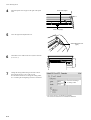
Change the Loadable Material Width to 280 to 305 mm (11
to 12 in.)
1
Raise the sheet adjustment lever on the right side.
Sheet adjustment lever
(right)
2
Detach the pinch-roller stopper from the machine.
Pinch-roller stopper
* When detaching the pinch-roller stopper, do not
use excessive force to widen the opening.
If the opening is widened, the pinch-roller
stopper may be loose or fall off the next time
you install it on the machine.
3
Move the right pinch roller in the direction of the arrow.
Pinch roller (right)
Move to here.
Continued on the next page
3-7
Part 3 Mastering the SX
4
Attach the pinch-roller stopper to the right of the pinch
roller.
Pinch-roller stopper
Pinch roller (right)
5
Lower the right sheet adjustment lever.
Sheet-adjustment lever
(right)
6
Load material of a width for the SX-12 (280 to 305 mm
(11 to 12 in.)).
7
Change the cutting-width setting for the SX-15 driver
from 340 mm to 250 (13.38 to 9.84 in.) mm.
For information about how to change the cutting width,
see "2.2 Setting the Cutting Range and Tool Conditions."
Click here and change
the cutting width.
* The screen shown is for Windows 95/98/Me.
The screens for Windows NT 4.0/2000 are different.
3-8
Part 3 Mastering the SX
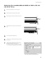
Returning the Loadable Material Width to 360 to 381 mm
(14-1/8 to 15 in.)
1
Raise the sheet adjustment lever on the right side.
2
Detach the pinch-roller stopper from the machine.
3
Move the right pinch roller in the direction of the arrow.
Pinch roller
(right)
4
Attach the pinch-roller stopper to the left of the pinch
roller.
Pinch roller
(right)
Pinch-roller stopper
5
Lower the right sheet adjustment lever.
6
Load material of a width for the SX-15 (280 to 305 mm
(11 to 12 in.)).
7
Change the cutting-width setting for the SX-15 driver
from 250 mm to 340 mm (9.84 to 13.38 in.).
For information about how to change the cutting width,
see "2.2 Setting the Cutting Range and Tool Conditions."
Click here and change
the cutting width.
* The screen shown is for Windows 95/98/Me.
The screens for Windows NT 4.0/2000 are different.
3-9
Part 3 Mastering the SX
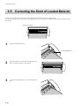
3.5 Correcting the Slant of Loaded Material
If material is not loaded parallel with respect to the machine, the material may come loose during cutting.
If you're using the SX-15/12, you can use the sheet adjustment lever to correct the slant of material without removing the material from
the machine.
Front of the machine
1
Raise the sheet adjustment lever.
Sheet adjustment lever
2
Move the material to the front and back and position it so
that it is straight with respect to the machine.
3
Lower the sheet adjustment lever to secure the material in
place.
3-10
Part 3 Mastering the SX
3.6 Importing Windows Bitmap Format
You can import files and created data in Windows bitmap format (having the file extension *.bmp) into Dr. STIKA PLUS, perform
outlining for the data, and cut the data on the SX-15/12/8.
Depending on the image that is imported, some shapes that result may not be suitable for cutting. Keep the following conditions in mind
as you create the data, then import it in Dr. STIKA PLUS. Refer to the documentation for the software you're using for information on
how to save files in Windows Bitmap format (with the file extension *.bmp).
Conditions for Data That Yields Attractive Cutting Results
-Boundaries between two colors should be sharp and well defined, with no continuous gradations.
In general, photographs and scanning data contain continuous gradations and are not suitable for cutting.
-The resolution should be high.
As a general guide, the original dimensions should be 200 dpi or higher.
It may take a long time to import high-resolution data into Dr. STIKA PLUS.
-The original image that you import should be the same size as or larger than the image to cut. .
When you import into Dr. STIKA PLUS an original image that is smaller than the size you want to cut, you cannot attractive
cutting results even by enlarging the image to the size you want. To obtain attractive cutting results, import an original image that
is larger than the cutting size, then reduce the image to the size you want.
For detailed information, see the PDF manual or help screens for Dr. STIKA PLUS.
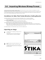
Importing an Image
1
At the [File] menu, click [Import] to display the screen
shown at right.
Click [File Type], then click [Windows Bitmap File
(*.bmp)]. Select the file to use, then click [Open].
2
The image appears in the [Preview] dialog box. Click
[OK].
To extract attractive outlines, refer to the preceding
"Conditions for data that yields attractive cutting results"
and create the data.
Continued on the next page
3-11
Part 3 Mastering the SX
3
The data in the selected file is imported.
Adjust the size and positioning.
The size of the imported original image and the size of the data imported into Dr. STIKA PLUS are different.
Refer to "2.2 Creating Cutting Data" and return the size of the object to the size you want.
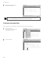
To Delete Unneeded Data
When an imported object includes unneeded data, you can delete the unnecessary data using Dr. STIKA PLUS.
1
Select the imported object.
At the [Object] menu, click [Break Apart].
The imported object is divided.
2
Click the unneeded data.
Unneeded data
3-12
Part 3 Mastering the SX
3
From the [Edit] menu, click [Delete].
The unneeded data is deleted.
4
Restore the divided object to its original state.
Use the mouse to drag and select all the objects you want
to combine.
At the [Object] menu, click [Combine Polygons].
To select all data in the Dr. STIKA PLUS window, go to
the [Edit] menu and click [Select All].
You can also select only the objects you want by holding
down the SHIFT key and selecting the objects.
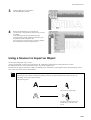
Using a Scanner to Import an Object
You can import image data using a scanner.
An image acquired with a scanner can be imported into Dr. STIKA PLUS and outlined for cutting with the SX-15/12/8.
For detailed information, see the PDF manual or help screens for Dr. STIKA PLUS.
Dr. STIKA PLUS supports scanners that comply with TWAIN32. For information on connecting the scanner and installing the scanner
driver, please refer to the scanner's documentation.
When you are scanning and cutting data such as bold logos, fill the original image before you scan it. Dr. STIKA
PLUS extracts the contours and performs outlining of objects. The portions that the SX-15/12/8 cuts may vary
depending on the original imported image.
Original image data
A
This is cut as a single object.
A
1
2
Two lines, one on the inner side
and the other on the outer side,
are cut.
3-13
Part 3 Mastering the SX
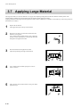
3.7 Applying Large Material
The larger the material is, the more difficult is it to apply while adjusting misalignment of the entire material, and the greater is the
likelihood that air bubbles will get trapped between the material and the application surface.
Applying detergent-containing water to the application surface makes it difficult for air bubbles to form and lets you move the position of
the material as you affix it.
1
Prepare the cut material.
Affix application tape to the top of the material.
2
Wipe away any dust or oil from the location where the
material is to be applied.
Use a commercially available mister to spray a generous
amount of water containing two or three drops of neutral
detergent to the application surface.
3
Place the material on the application surface.
Adjust the positioning and angle of the material.
4
Use a commercially available squeegee or a ruler to
remove moisture.
5
After you have removed all moisture, slowly peel off the
application tape.
3-14
Part 4 User's Reference
Part 4 User's Reference
4.1 Care and Maintenance
When using a commercially
available cutter knife for replacing
the blade protector, do not place the
hands anywhere along the path in
the direction of blade movement.
Doing so may result in injury.
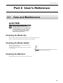
Cleaning the Blade Tip
Material scraps or adhesive adhering to the blade tip can adversely affect cutting.
Remove any buildup of material scraps or adhesive from the blade tip.
Cleaning the Blade Holder
Material scraps or grime that get inside the blade holder
can adversely affect cutting.
Take off the tip of the blade holder and remove any pieces
of material inside.
Rotate the tip of the blade holder in the direction
shown in the figure to remove it.
Cleaning the Machine
If the machine becomes soiled, wipe it clean with a dry cloth.
4-1
Part 4 User's Reference
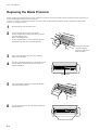
Replacing the Blade Protector
Slight scratching of the blade protector poses no problem for operation. However, the blade protector should be replaced if it becomes so
severely damaged that cutting is adversely affected.
Consult your vendor or your nearest Roland DG Corp. sales office for replacement of the blade protector. (Replacement of the blade
protector is a charged procedure.)
1
Switch off the power to the SX-15/12/8.
2
Peel off the blade protector from the machine.
Using a commercially available cutter knife or the like
may make peeling easier.
Remove the blade protector.
If you're using the SX-15, raise the left and right sheet
adjustment levers and remove the blade protector.
* Do not place the hands
anywhere along the
path in the direction of
blade movement.
3
Use a cloth or the like to wipe away any remaining
adhesive on the machine.
4
Place the replacement blade protector on the SX-15/12/8.
Use the reference line shown on the SX-15/12/8 as a
guide for alignment.
Reference line
5
Peel off the double-sided tape and attach the included
replacement blade protector.
6
If you're using the SX-15, lower the left and right sheet
adjustment levers.
Sheet adjustment levers
4-2
Part 4 User's Reference
4.2 What to do if...
The SX-15/12/8 doesn't operate.
Is the STANDBY key on (with the STANDBY LED lit up)?
The power is off. Press the STANDBY key.
Is the cable connected?
Switch off the power to the computer and the SX-15/12/8, and use a parallel cable (IEEE 1284-compliant) to connect the two
devices.
For information on how to make the connections, see "1.3 Connecting the Cables."
Is the correct type of cable used?
The type of parallel cable (IEEE 1284-compliant) may vary according to the computer model. Make the connection with the
correct type of cable for the computer.
Be sure the computer and the SX-15/12/8 are both switched off before attempting to attach or disconnect the printer cable
(IEEE 1284-compliant).
Is the STANDBY LED not flashing?
A communication error or command error has occurred.
Switch off the power and check the cable connections and port settings for the drivers.
Are the settings for the driver correct?
If the port setting is different from the port connected to the SX-15/12/8, make the setting for the connect port.
Is the printer port for Windows set to [ECP Printer Port]?
If the computer and the SX-15/12/8 are connected by a parallel cable and there is no operation, check the printer port for
Windows. If it is set to [ECP Printer Port], change it to [Printer Port]. For information on how to change the setting, contact the
manufacturer of your computer.
The SX-15/12/8 stops while cutting is in progress (and no error message appears on the computer screen).
Is the computer in energy-saving mode?
If the computer is in energy-saving mode, follow the steps below to turn off power management in Windows.
For information on how to change the setting, contact the manufacturer of your computer.
Pressing the STANDBY key does not switch off the power.
Unplug the AC adapter from the unit.
The Dr. STIKA PLUS doesn't function.
Does the computer you're using provide the correct operating environment for the included software?
Check "1.3 Operating Environment for Software" and make sure you're using a computer that meets the operating-environment
requirements.
Was the software installed using the setup program?
Be sure to use the setup program when installing the Dr. STIKA PLUS.
The setup program puts the files for each software package in the necessary locations to enable the software to be used under
Windows.
The system hangs (when you're using Windows NT 4.0 with Service Pack 3).
The system may hang when you type in text. This symptom is corrected by Windows NT 4.0 Service Pack 4 and later.
For more information, contact Microsoft.
4-3
Part 4 User's Reference
No squares or triangles (
and
) are displayed around objects.
Depending on the model of computer, squares and triangles ( and ) for manipulating objects may not be displayed. The
following two workarounds are available. They affect the entire operating environment of the computer. For information on how
to change the settings, also see the help screens for Windows. You can view help for Windows by right-clicking with the mouse
in the corresponding dialog box.
1. In Windows, open [Control Panels].
Double-click [Display] to display [Settings].
Set [Color] to [256] then click [OK].
2. In Windows, open [Control Panels].
Double-click [System] to display [Performance].
Click the [Graphics] button.
Move the [Hardware acceleration] bar to the left until the square and triangle symbols (
and
) around the objects appear.
Material cannot be cut properly.
Has the blade tip been adjusted?
Check whether the amount of blade extension has been adjusted. For information on how to adjust the amount of blade extension,
see "3.1 Adjusting and Replacing the Blade."
If the amount of blade extension is too short for the material
Cut lines may be discontinuous or unattractive, or the cutting results may be misaligned.
Adjust the length of blade extension to be the same as the thickness of the material.
If the amount of blade extension is too long for the material
The material may peel off during cutting.
Shorten the amount of blade extension and change the driver setting to make the cutting speed slower.
Is the blade holder secured in place?
If the blade holder is not secured in place, it may be impossible to cut material.
Install securely so that the screws do not loosen while cutting is in progress.
Is the blade broken?
Cut lines may be discontinuous or unattractive, or the cutting results may be misaligned.
Replace with a new blade.
Is the size of the loaded material set correctly?
Material smaller than the set cutting range has been loaded. Load material that matches the cutting range.
Is the cutting speed correct?
The cutting speed is too fast. Change the driver setting to obtain a slower cutting speed. Please refer to the relevant help screens
for the driver to set the cutting speed.
Is the driver for the model you're using installed?
Make sure the driver for the model you're using is installed.
If a driver for an incorrect model is installed, install the correct driver for the model you're using.
The material becomes misaligned during cutting.
When material measuring 500 mm or more is loaded.
When material measuring 500 mm (19-5/8 in.) or more is loaded, then depending on its type, it may become misaligned.
If this happens, then either replace the material with a different type, or reload the material.
When short (strip-shaped) material is loaded.
When short (strip-shaped) material is loaded, then depending on how little rigidity the material has, it may become misaligned
during cutting.
If this happens, then either replace the material with a different type, or load and use material that is longer than the material now
loaded.
4-4
Part 4 User's Reference
Cut lines are partially dotted (discontinuous).
The cause may be any of the follow.
Is the tip of the blade broken?
Replace with a new fresh, then use.
Is there any buildup of dust or material adhesive on the tip of the blade?
If there is buildup of dust or material adhesive, remove the blade and clean the tip.
Are there material scraps inside the blade holder?
Detach the tip of the blade holder and clean out any material inside the blade holder. See "4.4 Cleaning the Blade Holder" for the
procedure.
Is the blade protector damaged?
If material is cut correctly even though the blade and blade holder are installed correctly, it means that the blade protector is
damaged. Replace with a new blade protector. For information on how to replace it, see "4.1 Replacing the Blade Protector."
Is the blade holder broken or worn?
Replace with a new blade holder.
A message appears on the computer screen.
Is the message "Write error," "Out of paper," or "Timeout error" displayed on the computer screen?
Communication between the SX-15/12/8 and the computer is not correct. Switch off the power to the SX-15/12/8 and the
computer, then make sure the cable connections are correct. If you are using a cable switching device, remove the switching
device
Is the [Add Printer Wizard] window displayed?
Make sure the SX-15/12/8's driver is installed.
If you connect the SX-15/12/8 to the computer and switch on the power to the SX while the SX driver is not installed on the
computer, then when you start Windows, the message [Add Printer Wizard] appears.
Follow the steps below to install the driver.
1. Click [Cancel].
2. Install the driver for the model you're using from the Roland Software Package CD-ROM.
For information on how to install from the CD-ROM, see "1.4 Installing and Setting Up the Included Software."
4-5
Part 4 User's Reference
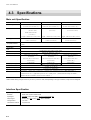
4.3 Specifications
Main unit Specification
SX-15
Max. cutting area
SX-12
SX-8
340 mm (X) x 1000 mm (Y)
250 mm (X) x 1000 mm (Y)
160 mm (X) x 1000 mm (Y)
(13-3/8 in. (X) x 39-5/16 in. (Y) )
(9-13/16 in. (X) x 39-5/16 in. (Y) )
(6-1/4 in. (X) x 39-5/16 in. (Y) )
Width : 360 to 381 mm
Width : 280 to 305 mm
Width : 200 to 215 mm
Acceptable sheet size*
(14-1/8 to 15 in.)
(11 to 12 in.)
(7-13/16 to 8-7/16 in.)
Width : 280 to 305 mm
(11 to 12 in.)
Length : 1100 mm (43-1/4 in.) or less
Length : 1100 mm (43-1/4 in.) or less
Length : 1100 mm (43-1/4 in.) or less
12 to 100 mm/sec.
12 to 40 mm/sec.
12 to 40 mm/sec.
(7/16 to 3-7/8 in./sec)
(7/16 to 1-9/16 in./sec)
(7/16 to 1-9/16 in./sec)
Cutting speed
Acceptable material
PVC sheet (0.1 mm (0.00394 in.) or less in thickness, 0.3 mm (0.0118 in.) or less in thickness including the backing
board).
Control keys
STANDBY key
LED
STANDBY LED
Parallel (IEEE 1284 compliant: Nibble mode)
Interface
Exclusive AC adapter DC+19V 2.1A
Power consumption
External dimensions
510 mm (W) x 165 mm (D) x
430 mm (W) x 165 mm (D) x
330 mm (W) x 165 mm (D) x
105 mm (H)
105 mm (H)
105mm (H)
(20-1/8 in. (W) x 6-1/2 in. (D) x
(16-15/16 in. (W) x 6-1/2 in. (D) x
(13 in. (W) x 6-1/2 in. (D) x
4-3/16 in. (H) )
4-3/16 in. (H) )
4-3/16 in. (H) )
2.6 Kg (5.7 lb)
2.1 Kg (4.6 lb)
3.1 Kg (6.8 lb)
Weight (unit only)
60 dB (A) or less (According to ISO 7779)
Acoustic noise level
5 to 40 °C (41 to 104 °F)
Operation temperature
35 to 80 % (no condensation)
Operation humidity
Accessories
AC adapter : 1, Power cord : 1, Ferrite cores : 2, Cable ties (For securing ferrite cores) :2, Blade holder/Blade : 1,
Material for test cuts : 1, Application tape for test cuts : 1, Blade protect : 1, Roland Software Package CD-ROM: 1,
Roland CutChoice CD-ROM:1, SX-15/12/8 User's Manual : 1
*When material having a length of 500 mm (19-5/8 in.) or more is used, then depending on the type of material, it may become misaligned.
Interface Specification
[ Parallel ]
Standard
IEEE 1284 compliant: Nibble mode
Input signal
STROBE (1BIT), DATA (8BIT), SLCT IN, AUTO FEED, INT
Output signal
BUSY (1BIT), ACK (1BIT), FAULT, SLCT, PERROR
I/O signal level
TTL level
Transmission method
Asynchronous
4-6
Part 4 User's Reference
Output from Roland CutChoice™
What's Roland CutChoice?
Roland CutChoice is a software plug-in for Adobe Illustrator and CorelDRAW. It lets you perform output to Windows or a Macintosh
using these programs.
CutChoice makes it simple for you to use such features as zoom in, zoom out, and copy, making it possible to obtain high-quality cutting
output.
System Requirements
Windows
Connection
: Parallel (IEEE 1284 compliant : Nibble mode)
USB/parallel conversion cable SX-UP2*
Operating system
: Windows 98/Me or Windows 2000
*Compatible computers : Computers on which USB operation is assured by the manufacturer
Compatible programs : Adobe Illustrator 8.0/9.0, CorelDRAW 8/9/10
Macintosh
Connection
Operating system
Compatible computers
Compatible programs
: USB/parallel conversion cable SX-UP2
: Mac OS 8.6 to 9.x (except Mac OS 9.0.2 to 9.0.3)
: Computers on which USB operation is assured by the manufacturer
: Adobe Illustrator 8.0/9.0
Viewing the User's Manual
The user's manual for CutChoice is in PDF format. You can find it on the included Roland CutChoice CD-ROM. For detailed information
about the features of CutChoice, see "Roland CutChoice.pdf."
- Acrobat Reader is required to view the PDF file. Install Acrobat Reader if it is not already installed and set up on
your computer.
Acrobat Reader is included on the roland CutChoice CD-ROM. Follow the step below to install it and set it up.
- Roland CutChoice cannot be used with other than a supported cutting-machine model. During installation and setup,
be sure to select the name of the model you're using.
* Windows *
1. Place the CD from the Roland CutChoice in the CD-ROM drive.
2. Installation of CutChoice starts automatically, and the [CD Setup] window appears.
3. Click [Cancel].
4. The message [If you quit setup now, you will have to reinstall the software. Are you sure you want to quit setup now?] appears.
Click [Yes] to quit setup.
5. Go into My Computer and select the CutChoice CD-ROM or the CD-ROM drive. Right-click, then select Explorer to open it.
(Alternatively, start Windows Explorer. Select the Roland CutChoice CD-ROM, then double-click to open it.)
Continued on the next page
4-7
Part 4 User's Reference
6. Install Acrobat Reader if it is not already installed and set up on your computer. On the CD-ROM, double-click the [Acrobat] folder
to open it, then double-click the [English] folder to open it. Double-click [ar405eng]. Installation of Acrobat Reader starts.
Follow the on-screen instructions to install and set up Acrobat Reader.
Alternatively, you can refer to "1-4 Installing and Setting Up Dr.STIKA PLUS and the Driver" to view the PDF manual for Dr.
STIKA PLUS. Acrobat Reader is installed automatically when you view the PDF manual for Dr. STIKA PLUS.
7. Read the PDF manual for Roland CutChoice.
Double-click the [Readme] folder, then double-click the [English] folder to open it.
8. Double-click "Roland CutChoice.pdf" and read the PDF manual.
* Macintosh *
1. Place the CD from the Roland CutChoice in the CD-ROM drive.
2. Install Acrobat Reader if it is not already installed and set up on your computer. On the CD-ROM, double-click the [Acrobat] folder
to open it, then double-click the [English] folder to open it. Double-click [Reader Installer]. Installation of Acrobat Reader starts.
Follow the on-screen instructions to install and set up Acrobat Reader.
3. Read the PDF manual for Roland CutChoice.
Double-click the [Help] folder, then double-click the [English] folder to open it.
4. Double-click "Roland CutChoice.pdf" and read the PDF manual.
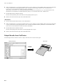
Output Results from CutChoice
The data displayed in the CutChoice window is output on the SX-15/12/8 as shown in the figure.
Roland CutChoice
SX-15/12/8
Output
4-8
For the USA
FEDERAL COMMUNICATIONS COMMISSION
RADIO FREQUENCY INTERFERENCE
STATEMENT
This equipment has been tested and found to comply with the
limits for a Class A digital device, pursuant to Part 15 of the
FCC Rules.
These limits are designed to provide reasonable protection
against harmful interference when the equipment is operated
in a commercial environment.
This equipment generates, uses, and can radiate radio
frequency energy and, if not installed and used in accordance
with the instruction manual, may cause harmful interference
to radio communications.
Operation of this equipment in a residential area is likely to
cause harmful interference in which case the user will be
required to correct the interference at his own expense.
Unauthorized changes or modification to this system can void
the users authority to operate this equipment.
The I/O cables between this equipment and the computing
device must be shielded.
For Canada
CLASS A
NOTICE
This Class A digital apparatus meets all requirements of the
Canadian Interference-Causing Equipment Regulations.
CLASSE A
AVIS
Cet appareil numérique de la classe A respecte toutes les
exigences du Règlement sur le matériel brouilleur du
Canada.
ROLAND DG CORPORATION
1-6-4 Shinmiyakoda, Hamamatsu-shi, Shizuoka-ken, JAPAN 431-2103
MODEL NAME
: See the MODEL given on the rating plate.
RELEVANT DIRECTIVE : EC LOW VOLTAGE DIRECTIVE (73/23/EEC)
EC ELECTROMAGNETIC COMPATIBILITY DIRECTIVE (89/336/EEC)
Please read this agreement carefully before opening the sealed
package or the sealed disk package
Opening the sealed package or sealed disk package implies your acceptance of the terms and conditions of this agreement.
Roland License Agreement
Roland DG Corporation ("Roland") grants you a non-assignable and non-exclusive right to use the COMPUTER
PROGRAMS in this package ("Software") under this agreement with the following terms and conditions.
1. Coming into Force
This agreement comes into force when you purchase and open the sealed package
or sealed disk package.
The effective date of this agreement is the date when you open the sealed package
or sealed disk package.
2. Property
Copyright and property of this Software, logo, name, manual and all literature
for this Software belong to Roland and its licenser.
The followings are prohibited :
(1) Unauthorized copying the Software or any of its support file, program module
or literature.
(2) Reverse engineering, disassembling, decompiling or any other attempt to
discover the source code of the Software.
3. Bounds of License
Roland does not grant you to sub-license, rent, assign or transfer the right granted
under this agreement nor the Software itself (including the accompanying items)
to any third party.
You may not provide use of the Software through time-sharing service and/or
network system to any third party who is not individually licensed to use this
Software.
You may use the Software by one person with using a single computer in which
the Software is installed.
4. Reproduction
You may make one copy of the Software only for back-up purpose. The property
of the copied Software belongs to Roland.
You may install the Software into the hard disk of a single computer.
5. Cancellation
Roland retains the right to terminate this agreement without notice immediately
when any of followings occurs :
(1) When you violate any article of this agreement.
(2) When you make any serious breach of faith regarding this agreement.
6. Limitations on Liability
Roland may change the specifications of this Software or its material without
notice.
Roland shall not be liable for any damage that may caused by the use of the
Software or by exercise of the right licensed by this agreement.
7. Governing Law
This agreement is governed by the laws of Japan, and the parties shall submit to
the exclusive jurisdiction of the Japanese Court.
R3-011213