1
BreezeACCESS V
Version 4.3
Revision 4.0A
June 2003
System Manual
Cat. No. Revision 4.0A 213482
© 2003 by Alvarion Ltd. All rights reserved.
No part of this publication may be reproduced in any material form without the written permission of
the copyright owner.
Trade Names
Alvarion®, BreezeACCESS®, BreezeCOM®, BreezeLINK®, BreezePHONE®, BreezeNET®,
WALKair®, WALKnet®, are trade names or trademarks of Alvarion Ltd. Other brand and product
names are trade names or trademarks of their respective owners.
Statement of Conditions
The information contained in this manual is subject to change without notice. Alvarion shall not be
liable for errors contained herein or for incidental or consequential damages in connection with the
furnishing, performance, or use of this manual or equipment supplied with it.
Warranties; Disclaimers
All Alvarion Ltd. (Alvarion) products purchased from Alvarion or through any of Alvarion’s
authorized resellers are subject to the following warranty and product liability terms and conditions.
Exclusive Warranty
Alvarion warrants that the Product hardware it supplies and the tangible media on which any software
is installed, under normal use and conditions, will be free from significant defects in materials and
workmanship for a period of fourteen (14) months from the date of shipment of a given Product to
Purchaser (the Warranty Period). Alvarion will, at its sole option and as Purchaser’s sole remedy,
repair or replace any defective Product in accordance with Alvarion’ standard RMA procedure.
Disclaimer
(a) UNITS OF PRODUCT (INCLUDING ALL THE SOFTWARE) DELIVERED TO
PURCHASER HEREUNDER ARE NOT FAULT-TOLERANT AND ARE NOT DESIGNED,
MANUFACTURED OR INTENDED FOR USE OR RESALE IN APPLICATIONS WHERE THE
FAILURE, MALFUNCTION OR INACCURACY OF PRODUCTS CARRIES A RISK OF DEATH
OR BODILY INJURY OR SEVERE PHYSICAL OR ENVIRONMENTAL DAMAGE (HIGH
RISK ACTIVITIES). HIGH RISK ACTIVITIES MAY INCLUDE, BUT ARE NOT LIMITED TO,
USE AS PART OF ON-LINE CONTROL SYSTEMS IN HAZARDOUS ENVIRONMENTS
REQUIRING FAIL-SAFE PERFORMANCE, SUCH AS IN THE OPERATION OF NUCLEAR
FACILITIES, AIRCRAFT NAVIGATION OR COMMUNICATION SYSTEMS, AIR TRAFFIC
CONTROL, LIFE SUPPORT MACHINES, WEAPONS SYSTEMS OR OTHER APPLICATIONS
REPRESENTING A SIMILAR DEGREE OF POTENTIAL HAZARD. ALVARION
SPECIFICALLY DISCLAIMS ANY EXPRESS OR IMPLIED WARRANTY OF FITNESS FOR
HIGH RISK ACTIVITIES.
(b) PURCHASER’S SOLE REMEDY FOR BREACH OF THE EXPRESS WARRANTIES
ABOVE SHALL BE REPLACEMENT OR REFUND OF THE PURCHASE PRICE AS SPECIFIED
ABOVE, AT ALVARION’S OPTION. TO THE FULLEST EXTENT ALLOWED BY LAW, THE
WARRANTIES AND REMEDIES SET FORTH IN THIS AGREEMENT ARE EXCLUSIVE AND
IN LIEU OF ALL OTHER WARRANTIES OR CONDITIONS, EXPRESS OR IMPLIED, EITHER
IN FACT OR BY OPERATION OF LAW, STATUTORY OR OTHERWISE, INCLUDING BUT
NOT LIMITED TO WARRANTIES, TERMS OR CONDITIONS OF MERCHANTABILITY,
FITNESS FOR A PARTICULAR PURPOSE, SATISFACTORY QUALITY, CORRESPONDENCE
WITH DESCRIPTION, NON-INFRINGEMENT, AND ACCURACY OF INFORMATION
GENERATED. ALL OF WHICH ARE EXPRESSLY DISCLAIMED. ALVARION’ WARRANTIES
HEREIN RUN ONLY TO PURCHASER, AND ARE NOT EXTENDED TO ANY THIRD
PARTIES. ALVARION NEITHER ASSUMES NOR AUTHORIZES ANY OTHER PERSON TO
ASSUME FOR IT ANY OTHER LIABILITY IN CONNECTION WITH THE SALE,
INSTALLATION, MAINTENANCE OR USE OF ITS PRODUCTS.
BreezeACCESS Version 4.3 System Manual
ii
(c) ALVARION SHALL NOT BE LIABLE UNDER THIS WARRANTY IF ITS TESTING AND
EXAMINATION DISCLOSE THAT THE ALLEGED DEFECT IN THE PRODUCT DOES NOT
EXIST OR WAS CAUSED BY PURCHASER’S OR ANY THIRD PERSON'S MISUSE,
NEGLIGENCE, IMPROPER INSTALLATION OR IMPROPER TESTING, UNAUTHORIZED
ATTEMPTS TO REPAIR, OR ANY OTHER CAUSE BEYOND THE RANGE OF THE
INTENDED USE, OR BY ACCIDENT, FIRE, LIGHTNING OR OTHER HAZARD.
Limitation Of Liability.
(a) ALVARION SHALL NOT BE LIABLE TO THE PURCHASER OR TO ANY THIRD PARTY,
FOR ANY LOSS OF PROFITS, LOSS OF USE, INTERRUPTION OF BUSINESS OR FOR ANY
INDIRECT, SPECIAL, INCIDENTAL, PUNITIVE OR CONSEQUENTIAL DAMAGES OF ANY
KIND, WHETHER ARISING UNDER BREACH OF CONTRACT, TORT (INCLUDING
NEGLIGENCE), STRICT LIABILITY OR OTHERWISE AND WHETHER BASED ON THIS
AGREEMENT OR OTHERWISE, EVEN IF ADVISED OF THE POSSIBILITY OF SUCH
DAMAGES.
(b) TO THE EXTENT PERMITTED BY APPLICABLE LAW, IN NO EVENT SHALL THE
LIABILITY FOR DAMAGES HEREUNDER OF ALVARION OR ITS EMPLOYEES OR
AGENTS EXCEED THE PURCHASE PRICE PAID FOR THE PRODUCT BY PURCHASER,
NOR SHALL THE AGGREGATE LIABILITY FOR DAMAGES TO ALL PARTIES
REGARDING ANY PRODUCT EXCEED THE PURCHASE PRICE PAID FOR THAT
PRODUCT BY THAT PARTY (EXCEPT IN THE CASE OF A BREACH OF A PARTY’S
CONFIDENTIALITY OBLIGATIONS).
Electronic Emission Notice
This device complies with Part 15 of the FCC rules. Operation is subject to the following two
conditions:
1. This device may not cause harmful interference.
2. This device must accept any interference received, including interference
that may cause undesired operation.
FCC Radio Frequency Interference Statement
This equipment has been tested and found to comply with the limits for a class A digital device,
pursuant to Part 15 of the FCC rules. These limits are designed to provide reasonable protection
against harmful interference when the equipment is operated in a commercial environment. This
equipment generates, uses, and can radiate radio frequency energy and, if not installed and used in
accordance with the instruction manual, may cause harmful interference to radio communications.
Operation of this equipment in a residential area is likely to cause harmful interference in which case
the user will be required to correct the interference at his own expense.
FCC Radiation Hazard Warning
To comply with FCC RF exposure requirements in section 1.1307, a minimum separation distance of
2 m (79 inches) is required between the antenna and all persons:
Safety Considerations
For the following safety considerations, “Instrument” means the BreezeACCESS units’ components
and their cables.
Caution
To avoid electrical shock, do not perform any servicing unless you are qualified to do so.
Important Notice
iii
BS-GU Lithium Battery
Caution: Danger of battery explosion if incorrectly replaced or disposed of. Replace only with the
same or equivilant type battery, as recommended by the manufactuer. Dispose of used batterys
according to manufactuer’s instructions.
Line Voltage
Before connecting this instrument to the power line, make sure that the voltage of the power source
matches the requirements of the instrument.
Power Cord
Use only the power cord supplied with the unit.
Radio
The instrument transmits radio energy during normal operation. To avoid possible harmful exposure
to this energy, do not stand or work for extended periods of time in front of its antenna. The long-term
characteristics or the possible physiological effects of Radio Frequency Electromagnetic fields have
not been yet fully investigated.
Outdoor Unit and Antenna Installation and Grounding
Be sure that the outdoor unit, the antenna and the supporting structure are properly installed to
eliminate any physical hazard to either people or property. Verify that the outdoor unit and the
antenna mast (when using external antenna) are grounded so as to provide protection against voltage
surges and static charges. Make sure that the installation of the outdoor unit, antenna and cables is
performed in accordance with all relevant national and local building and safety codes.
This equipment can be operated in the range of frequency and transmitted power in accordance with
National Radio Regulations. The manufacturer is not responsible for the changes and modifications
made by the user
BreezeACCESS Version 4.3 System Manual
iv
Important Notice
This user manual is delivered subject to the following conditions and
restrictions:
This manual contains proprietary information belonging to Alvarion
Ltd. Such information is supplied solely for the purpose of assisting
properly authorized users of the respective Alvarion Ltd. products.
No part of its contents may be used for any other purpose, disclosed
to any person or firm or reproduced by any means, electronic and
mechanical, without the express prior written permission of
Alvarion Ltd.
The text and graphics are for the purpose of illustration and
reference only. The specifications on which they are based are
subject to change without notice.
The software described in this document is furnished under a
license. The software may be used or copied only in accordance with
the terms of that license.
Information in this document is subject to change without notice.
Corporate and individual names and data used in examples herein
are fictitious unless otherwise noted.
Alvarion Ltd. reserves the right to alter the equipment specifications
and descriptions in this publication without prior notice. No part of
this publication shall be deemed to be part of any contract or
warranty unless specifically incorporated by reference into such
contract or warranty.
The information contained herein is merely descriptive in nature,
and does not constitute an offer for the sale of the product described
herein.
Any changes or modifications of equipment not expressly approved
by Alvarion Ltd. could void the user’s authority to operate the
equipment.
Some of the equipment provided by Alvarion and specified in this
manual, is manufactured and warranted by third parties. All such
equipment must be installed and handled in full compliance with the
instructions provided by such manufacturers as attached to this
manual or provided thereafter by Alvarion or the manufacturers. Noncompliance with such instructions may result in serious damage and/
or bodily harm and/or void the user’s authority to operate the
equipment and/or revoke the warranty provided by such manufacturer
Important Notice
v
.
NOTE:
The currently released BreezeACCESS V product line does not include certain products
and features which are described in this manual. These include the following:
SU-E Subscriber units with a connector for an external antenna
Subscriber Units with voice support
BreezeMANAGE
vi
BreezeACCESS Version 4.3 System Manual
Table of Contents
i
Table of Contents
System Manual Book 1:
System Description
Introduction ............................................................. 1-1
Introducing BreezeACCESS ..................................................... 1-2
System Components ................................................ 2-1
Subscriber Units (Customer Premises Equipment) ............... 2-2
SU-A/E Units with an Outdoor Radio Unit and Antenna .... 2-2
Base Station Equipment ........................................................... 2-4
Modular Base Station Equipment ...................................... 2-4
AU-E-NI Standalone “Micro-Cell” Access Unit ................... 2-7
Networking Equipment ............................................................. 2-8
Management Systems ............................................................... 2-8
BreezeMANAGE ................................................................ 2-9
BreezeCONFIG ................................................................ 2-10
Specifications .......................................................... 3-1
System Specifications .............................................................. 3-2
Radio and Modem 5.2 GHz Band ..................................... 3-2
Radio and Modem 5.7 GHz Band ...................................... 3-2
Data Communication ......................................................... 3-3
Voice/Fax (Subscriber Units with voice support) ............... 3-3
Telephony (Subscriber Units with voice support) ............... 3-4
IF Indoor – Outdoor Communication .................................. 3-4
(SU-A/E, AU-E-NI, AU-E-BS) ............................................. 3-4
Configuration and Management ......................................... 3-4
GU-RA GPS Radio ............................................................ 3-5
GU-RA to BS-GU Communication ..................................... 3-5
Environmental .................................................................... 3-5
Standards Compliance, General ........................................ 3-6
Physical Specifications ............................................................ 3-7
SU-A/E Subscriber Unit ..................................................... 3-7
AU-E-NI Stand-Alone Access Unit ..................................... 3-8
Modular Base Station Equipment ...................................... 3-9
Manual Revision 4.0
BreezeACCESS 4.3 System Manual
ii
System Manual Book 2:
Installation
IF-Based Equipment ................................................ 1-1
Modular Base Station Equipment ...................................... 1-2
Standalone AU-E-NI Access Unit ...................................... 1-3
Other Items Required for Installation ................................. 1-3
Guidelines for Selection of Equipment Locations ................. 1-5
AU-RE ................................................................................ 1-5
SU-RA and SU-RE ............................................................. 1-5
IF Cable ............................................................................. 1-6
Indoor Equipment ............................................................... 1-6
Installing the Outdoor Unit ....................................................... 1-7
The Outdoor Unit Bottom Panel ......................................... 1-7
Pole Mounting the Outdoor Unit ......................................... 1-9
Connecting the Antenna Cable (SU-RE and AU-RE) ...... 1-11
Installing the SU-NI and AU-NI Indoor Unit ........................... 1-12
Installing the SU-NI/AU-NI Unit ........................................ 1-13
Installing Modular Base Station Equipment ......................... 1-14
BS-SH Slot Assignments ................................................. 1-14
The BS-PS ....................................................................... 1-15
The BS-PS-AC ................................................................. 1-16
The BS-AU ....................................................................... 1-17
BS-SH Chassis and Modules Installation Procedure ....... 1-18
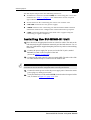
Installing the GU-A-BS GPS and Alarms System ................. 1-20
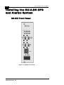
BS-GU Front Panel .......................................................... 1-20
Installing the GU-RA GPS Antenna ................................. 1-22
Installing the BS-GU module ............................................ 1-23
Daisy-chaining Two or More BS-GU Modules ................. 1-23
Table of Contents
System Manual Book 3:
Commissioning
Setting Basic Parameters ....................................... 1-1
Accessing the Monitor Program .............................................. 1-2
Accessing the Monitor Program using
the RS 232 MON Connector ............................................. 1-2
Accessing the Monitor Program using Telnet .................... 1-3
Operating the Monitor Program ......................................... 1-4
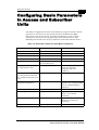
Configuring Basic Parameters in Access
and Subscriber Units ................................................................ 1-5
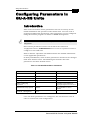
Configuring Parameters in GU-A-BS Units ............................. 1-7
Introduction ........................................................................ 1-7
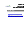
Optimizing the Wireless Link .................................. 2-1
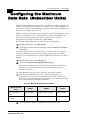
Configuring the Maximum Data Rate (Subscriber Units) ... 2-2
Aligning the Antenna of the SU-A/E Subscriber Unit ............. 2-3
BS-GU Connectors ................................................... 3-1
Connecting External Devices to the BS-GU AL IN
and/or AL OUT Connectors ...................................................... 3-2
Alarms In Cable ................................................................. 3-2
Alarms Out Cable ............................................................... 3-3
GPS Cable ......................................................................... 3-3
SYNC Cable ....................................................................... 3-5
Verifying Proper Operation ...................................... 4-1
Verifying Connectivity .............................................................. 4-2
Verifying the Ethernet Connection ..................................... 4-2
Verifying Data Connectivity (Subscriber Unit) .................... 4-2
Verifying Telephone Connectivity
(Subscriber Units with Voice support) ................................ 4-2
Verifying Proper Operation of the GU-A-BS GPS Unit ...... 4-3
LED Indicators ........................................................................... 4-4
SU-RA/RE Outdoor Units LEDs ......................................... 4-4
AU-RE Outdoor Units LEDs ............................................... 4-4
SU-NI and AU-NI Indoor Units LEDs ................................. 4-5
BS-PS DC Power Supply Module LEDs ............................ 4-5
BS-PS-AC AC Power Supply Module LEDs ...................... 4-5
BS-AU LEDs ...................................................................... 4-6
BS-GU LEDs ...................................................................... 4-6
Manual Revision 4.0
iii
BreezeACCESS 4.3 System Manual
iv
System Manual Book 4:
Operations and Administration
Accessing the Monitor Program .............................. 1-1
Accessing the Monitor Program using
the RS 232 MON Connector ...................................................... 1-2
Accessing the Monitor Program using Telnet ........................ 1-3
Operating the Monitor Program ............................................... 1-4
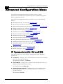
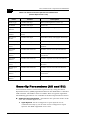
Menus and Parameters ............................................ 2-1
Main Menu .................................................................................. 2-2
Info Screens Menu .................................................................... 2-3
Show Unit Status ............................................................... 2-3
Show Basic Parameters ..................................................... 2-5
Show Advanced Parameters ............................................. 2-5
Show All Parameters ......................................................... 2-5
Unit Control Menu ..................................................................... 2-6
Basic Configuration Menu ...................................................... 2-13
Site Survey Menu .................................................................... 2-15
Traffic Statistics (AU and SU) .......................................... 2-15
Voice Statistics (SU with Voice Support Only) ................. 2-18
Per Hop Statistics (AU and SU) ....................................... 2-18
Ping Test (AU, SU and GU) ............................................. 2-19
Continuous Link Quality Display (Available in SU Only) .. 2-20
MAC Address Database (Available in AU Only) .............. 2-20
Per-rate Counters (AU and SU) ....................................... 2-23
RSSI Display Option (AU and SU) ................................... 2-23
ATPC Counter (AU and SU) ............................................ 2-23
AU Alarms (IF-based AU Only) ........................................ 2-24
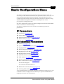
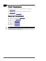
Advanced Configuration Menu .............................................. 2-36
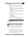
IP Parameters (AU, SU and GU) ..................................... 2-36
Air Interface Parameters (AU and SU) ............................. 2-37
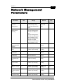
Network Management Parameters (AU, SU and GU) ..... 2-66
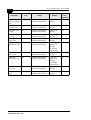
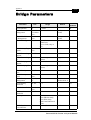
Bridge Parameters (AU, SU and GU) .............................. 2-69
Performance Parameter (AU and SU) ............................. 2-86
RADIUS Parameters Menu (Subscriber Units only) ....... 2-90
Security Parameters (AU and SU) ................................... 2-94
Voice Parameters
(Subscriber Units with Voice Support Only) .................... 2-96
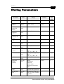
Dialing Parameters
(Subscriber Units with Voice Support Only) .................... 2-97
Table of Contents
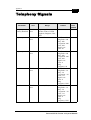
Telephony Signals
(Subscriber Units with Voice Support Only) ................... 2-104
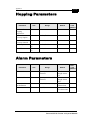
Hopping Parameters (GU) ............................................. 2-110
Alarm Parameters (GU) ................................................. 2-112
System Manual:Appendices
Appendix A: Configuration Download/Upload .........A-1
Appendix B: Software Version Loading Procedure B-1
General ...................................................................................... B-1
Loading an Upgrade to a Unit with FLASH Type: F .............. B-2
Loading an Upgrade to a Unit with FLASH Type: S .............. B-4
Appendix C: Supported MIBs and Traps .................C-1
BreezeACCESS System Object Identifiers ............................. C-2
brzAccessMIB ........................................................................... C-3
Service Parameters .......................................................... C-3
RADIUS General Parameters ........................................... C-4
Accounting Parameters ..................................................... C-4
RADIUS Authentication Parameters ................................. C-5
User Filtering Parameters ................................................. C-5
Network Management Parameters ................................... C-7
Bridge Parameters ............................................................ C-9
Air Interface Parameters ................................................. C-11
Performance Parameters ................................................ C-22
Site Survey Parameters .................................................. C-24
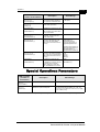
Special Operations Parameters ...................................... C-33
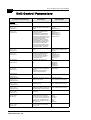
Unit Control Parameters ................................................. C-34
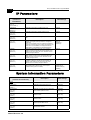
IP Parameters ................................................................. C-36
System Information Parameters ..................................... C-36
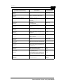
Alarms Parameters ......................................................... C-38
brzPhoneMIB (applicable to SU with voice only) ................ C-39
Dialing Parameters ......................................................... C-39
Voice Parameters ........................................................... C-42
Telephony Signals .......................................................... C-43
General Info MIB ............................................................. C-44
Supported Traps ..................................................................... C-44
Trap Associated Parameters .......................................... C-44
Traps ............................................................................... C-46
Manual Revision 4.0
v
vi
BreezeACCESS 4.3 System Manual
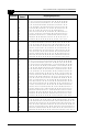
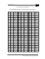
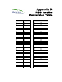
Appendix D: RSSI to dBm Conversion Table ...........D-1
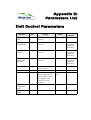
Appendix E: Parameters List ................................... E-1
Unit Control Parameters ...........................................................E-1
Site Survey Parameters ............................................................E-2
IP Parameters ............................................................................E-3
Air Interface Parameters ...........................................................E-4
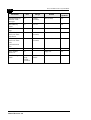
Network Management Parameters ...........................................E-7
Bridge Parameters ....................................................................E-9
Performance Parameters ........................................................E-11
Service Parameters .................................................................E-12
RADIUS Parameters ................................................................E-13
Security Parameters ................................................................E-13
Voice Parameters ....................................................................E-14
Dialing Parameters ..................................................................E-15
Telephony Signals ...................................................................E-17
Hopping Parameters ...............................................................E-19
Alarm Parameters ....................................................................E-19
BreezeACCESS V
Version 4.3
Revision 4.0
System Manual Book 1:
System Description
System Description
Table of Contents
Introduction .............................................................1-1
Introducing BreezeACCESS .....................................................1-2
System Components ................................................2-1
Subscriber Units (Customer Premises Equipment) ...............2-2
SU-A/E Units with an Outdoor Radio Unit and Antenna .....2-2
Base Station Equipment ...........................................................2-4
Modular Base Station Equipment .......................................2-4
AU-E-NI Standalone “Micro-Cell” Access Unit ...................2-7
Networking Equipment ..............................................................2-8
Management Systems ...............................................................2-8
BreezeMANAGE ................................................................2-9
BreezeCONFIG ................................................................2-10
Specifications ..........................................................3-1
System Specifications ...............................................................3-2
Radio and Modem 5.2 GHz Band .....................................3-2
Radio and Modem 5.7 GHz Band ......................................3-2
Data Communication ..........................................................3-3
Voice/Fax (Subscriber Units with voice support) ................3-3
Telephony (Subscriber Units with voice support) ...............3-4
IF Indoor – Outdoor Communication ..................................3-4
(SU-A/E, AU-E-NI, AU-E-BS) .............................................3-4
Configuration and Management .........................................3-4
GU-RA GPS Radio .............................................................3-5
GU-RA to BS-GU Communication .....................................3-5
Environmental ....................................................................3-5
Standards Compliance, General ........................................3-6
Physical Specifications .............................................................3-7
SU-A/E Subscriber Unit ......................................................3-7
AU-E-NI Stand-Alone Access Unit .....................................3-8
Modular Base Station Equipment .......................................3-9
ii
BreezeACCESS Version 4.3 System Description
Chapter 1
Introduction
About This Chapter
This chapter introduces the BreezeACCESS system, its components and
its functions.
BreezeACCESS Version 4.3 System Description
1-2
Introducing BreezeACCESS
BreezeACCESS IP Broadband Wireless Access system is an IP based
access system that supports wireless data and voice services, employing
wireless packet-switched data technology to support high-speed IP
services, including fast access to the Internet and Virtual Private
Networks.
BreezeACCESS users are provided with a network connection that is
always on, supporting access to the Internet and other IP services at
data rates of up to 3 Mbps. BreezeACCESS can also support high
quality telephony using the ITU-T H.323 industry standard for Voice
over IP communications. The system is designed for cellular-like
deployment, allowing systems of various sizes and structures to be
constructed. A system may include any number of cells, each
containing several Access Units, to better cover densely populated
areas.
The BreezeACCESS system allows the Maximum (data burst)
Information Rate (MIR) and Committed Information Rate (CIR) for both
uplink and downlink to be defined separately for each subscriber.
This enables a variety of Class of Service (CoS) packages, bandwidth
allocations and traffic-shaping schemes. In addition, the system
supports Virtual LANs based on IEEE 802.1Q, enabling secure
operation and Virtual Private Network (VPN) services as well as allowing
tele-workers or remote offices to conveniently access their enterprise
networks. The system also supports Layer 2 traffic prioritization
according to IEEE 802.1p and ToS based Layer 3 traffic prioritization
according to RFC791.
BreezeACCESS V operates in Time Division Duplex (TDD) mode. It
employs wireless packet data switching technology, utilizing Frequency
Hopping Spread Spectrum (FH-SS) radios.
BreezeACCESS V systems are available in the following frequency
bands:
Series (band)
Frequency Band
5.2
5.150-5.350 GHz
5.7
5.725-5.850 GHz
BreezeACCESS V units operating in the 5.7 GHz band are available with
one of the following options:
US Option – The available band ranges from 5.725 GHz to
5.850 GHz. This option supports the standard ISM US FCC
Frequency Hopping sequence that includes 79 frequencies.
Synchronization among AUs is not supported.
Manual Revision: 4.0
Introduction
1-3
INT (International) Option – The available band ranges from
5.725 GHz to 5.850 GHz. Two hopping sequence selection modes
are supported as follows:
a.
INT ISM mode: This option supports the standard ISM US FCC
Frequency Hopping sequence that includes 79 frequencies.
Synchronization among AUs is supported.
b.
Flexible Hopping Mode: Enables the selection of hopping
frequencies in the supported range. Synchronization among
AUs is supported.
A BreezeACCESS-based system consists of the following:
Customer Premise Equipment (CPE) – BreezeACCESS Subscriber
Units.
Base Station Equipment (BSE) – BreezeACCESS Access Units and
supporting equipment.
Networking Equipment – Standard Routers and/or
Gateways/Gatekeepers supporting connections to the Internet
and/or the PSTN or private telephony network.
Management Systems – SNMP based Management, Billing and
Customer Care, and other Operations Support Systems.
BreezeACCESS Version 4.3 System Manual
1-4
Manual Revision: 4.0
BreezeACCESS Version 4.3 System Description
Chapter 2
System
Components
About This Chapter
This chapter describes BreezeACCESS system components. It includes
the following sections:
Subscriber Units (Customer Premises Equipment)‚ page 2-2,
describes BreezeACCESS equipment installed at the customer’s
premises.
Base Station Equipment‚ page 2-4, describes the equipment used
in BreezeACCESS Base Stations.
Networking Equipment‚ page 2-8, describes how BreezeACCESS
Base Station units are connected to one another and to other
equipment in a network environment.
Management Systems‚ page 2-8, introduces the management
features built into the BreezeACCESS system and describes the use
of various standard and proprietary management systems.
BreezeACCESS Version 4.3 System Description
2-2
Subscriber Units (Customer
Premises Equipment)
The BreezeACCESS Subscriber Unit (SU) installed at the customer
premises provides data only or data and telephone connections. The
data connection is a standard IEEE 802.3 Ethernet 10BaseT (RJ 45)
interface while the voice connection (in units that support voice) is a
standard RJ 11 Plain Old Telephone (POTS) interface.
The Subscriber Unit provides an efficient platform for high rate Internet
and Intranet services, providing subscribers with fast access to IP based
services at a burst data rate of up to 3 Mbps. The use of packet
switching technology provides the user with a connection to the network
that is practically always on, allowing for immediate access to services.
SU-A/E Units with an Outdoor Radio
Unit and Antenna
SU-A and SU-E series Subscriber Units are comprised of an indoor unit
(SU-NI) and an outdoor unit.
In the SU-A series, the outdoor unit (SU-RA) contains the radio
module and an integral flat antenna.
In the SU-E series, the outdoor unit (SU-RE) contains the radio
module and an RF connector for an external antenna.
The indoor SU-NI unit connects to the user’s equipment and is powered
from the mains via its SU-PS power supply unit. The SU-NI is connected
to the outdoor unit via a 50-ohm coaxial Intermediate Frequency (IF)
cable. This cable carries 440 MHz IF signals between the indoor and the
outdoor units and also serves for transferring power (12 VDC),
management and control signals from the indoor unit to the outdoor
unit.
Manual Revision: 4.0
System Components
2-3
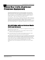
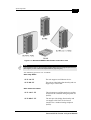
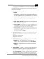
Figure 2-1: BreezeACCESS SU-A/E Outdoor and Indoor Units
NOTE:
Units operating in the 5.7 GHz band are supplied either with a rectangle shaped antenna
(left of figure), or with a diamond shaped antenna (right of figure).
The following products are available:
Data-only Units:
SU-X-1D- FF
The unit supports one Ethernet device.
SU-X-BD- FF
The unit provides bridge functionality and can
support up to a full LAN.
Data and Voice Units:
SU-X-1D1V- FF
The unit supports one Ethernet device and has
an interface to a standard analog telephone set
(POTS).
SU-X-BD1V- FF
The unit provides bridge functionality and
can support a full LAN. It also has an
interface for a standard analog telephone
(POTS).
BreezeACCESS Version 4.3 System Manual
BreezeACCESS Version 4.3 System Description
2-4
X=A: The outdoor radio unit includes an integral high gain flat antenna
X=E: The outdoor radio unit has a connector for an external antenna.
FF: The radio band supported by the unit (5.2 or 5.7 GHz).
Base Station Equipment
The BreezeACCESS Access Units (AU) installed at the base station site
provide all the functionality necessary to communicate with the remote
Subscriber Units as well as to connect to the backbone of the service
provider. Each AU connects to the network through a standard IEEE
802.3 Ethernet 10BaseT (RJ 45) interface.
There are 2 lines of Access Units with different architectures:
Modular Base Station Equipment
Standalone “Micro-Cell” Access Unit
Modular Base Station Equipment
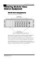
The Base Station equipment is based on the BS-SH 3U chassis, which is
suitable for installation in 19” racks. The chassis contains one or two
power supply modules, up to six active Access Unit Network Interface
(BS-AU) modules and an optional BS-GU GPS and Alarms module.
Two different types of power supply modules are available: the BS-PS
which is powered from a –48 VDC power source, and the BS-PS-AC,
powered from the 110/230 VAC mains. The optional use of two power
supply modules is for fail-safe operation through power supply
redundancy.
Each BS-AU module, together with its outdoor radio unit comprises an
AU-E-BS Access Unit that serves a single sector. The AU-RE outdoor
unit contains the radio module and a RF connector for a separate
external antenna.The BS-AU modules connect to the network through
standard IEEE 802.3 Ethernet 10BaseT (RJ 45) interfaces. A coaxial
Intermediate Frequency (IF) cable connects the indoor module to the
outdoor unit. This cable carries 440 MHz IF signals, power (12 VDC)
and management and control signals from the indoor unit to the
outdoor unit.
Manual Revision: 4.0
System Components
2-5
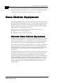
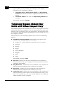
Figure 2-2: BreezeACCESS Base Station Module and Outdoor Unit
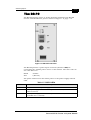
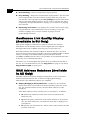
GU-A-BS GPS and Alarms System
The optional GU-A-BS system can be used to synchronize the frequency
hopping mechanisms of collocated AU-E-BS BreezeACCESS units
(where such synchronization is permitted by local regulations) as well as
to provide alarm management.
The GU-A-BS system is comprised of two units:
An outdoor GPS Receiver and Antenna unit, the GU-RA.
An indoor GPS and Alarms module, the BS-GU.
BreezeACCESS Version 4.3 System Manual
BreezeACCESS Version 4.3 System Description
2-6
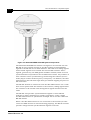
Figure 2-3: BreezeACCESS GU-A-BS System Components
The BreezeACCESS BS-GU module is designed to be inserted into the
BS-SH 19” base station chassis to provide hopping synchronization
signals to the BS-AU Access Unit modules. The card uses timing signals
derived from signals received from the GU-RA GPS antenna. These
signals, generated by the GPS global satellites network, allow accurate
synchronization of systems located in different locations. Any number of
base stations can be synchronized, guaranteeing that all AUs (Access
Units) hop in unison from frequency to frequency. In addition, the GPS
signal insures that all units begin their pre-defined hopping sequence at
the same time.
The BS-GU module is connected to the GU-RA GPS antenna via a cable
that carries power from the module to the antenna, timing signals from
the antenna to the module and management signals between the two
units.
The BS-GU also provides synchronization signals to other BS-GU
modules by daisy-chaining any number of modules, using a single
GU-RA GPS antenna to synchronize multiple AUs in several collocated
BS-SH chassis.
When a GU-RA GPS antenna is not connected to the module (or if the
connected GPS antenna is not functioning properly), the BS-GU module
provides self-generated synchronization signals to all AUs.
Manual Revision: 4.0
System Components
2-7
Daisy-chained BS-GU modules use the synchronization signals
generated by the first module in the chain (the Master module.
The BS-GU module also supports the management of alarm inputs and
outputs. The module receives Alarms In indications from other
BreezeACCESS modules in the base station shelf (internal alarms) and
external alarms from other devices via the AL IN connector. Alarms Out
management allows activation of external devices upon occurrence of
user-defined events, using relays via the AL OUT connector.
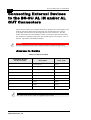
AU-E-NI Standalone “Micro-Cell”
Access Unit
The AU-E-NI is a standalone Access Unit that is very similar to the
AU-E-BS unit, the only difference being that the indoor unit, the AU-NI,
is a standalone desktop or wall-mountable unit rather than a 19”
module.
Figure 2-4: BreezeACCESS AU-NI Unit
The AU-RE outdoor unit is identical to that of the AU-E-BS line. The
AU-NI indoor unit is powered from the mains (100-250 VAC) through an
external power transformer and connects to the network through a
standard IEEE 802.3 Ethernet 10BaseT (RJ 45) interface. A coaxial
Intermediate Frequency (IF) cable connects between the AU-NI indoor
unit and the outdoor unit. This cable carries 440 MHz IF signals, power
(12 VDC) and management and control signals from the indoor unit to
the outdoor unit.
BreezeACCESS Version 4.3 System Manual
BreezeACCESS Version 4.3 System Description
2-8
Networking Equipment
The base station equipment is connected to the backbone through
standard data communication and telecommunication equipment. For
improved security, the 10BaseT ports of the AU modules are connected
directly to a multi-port router. This router is connected by any means of
point-to-point link to the backbone. In cases where security is less
important and cost is the main concern, the Access Units can be
connected to an Ethernet switch and then to a single port router.
The point-to-point link from the base station to the backbone may be
wired or wireless links. The data to the Internet is routed to the Internet
backbone through standard routers. The voice traffic is routed via
standard Gateways/Gatekeepers to the PSTN.
Management Systems
The end-to-end IP based architecture of the system allows full
management of all components from any point in the system.
BreezeACCESS components can be managed using standard
management tools through SNMP (Simple Network Management
Protocol) agents that implement standard and proprietary MIBs for
remote setting of operational modes and parameters. The same SNMP
management tools can also be used for management of other system
components including Switches, Routers, Gateways/Gatekeepers and
transmission equipment.
The Ethernet WAN can also be used to connect to other Operation
Support Systems including servers, Customer Care systems and AAA
(Authentication, Authorization and Admission) tools.
Manual Revision: 4.0
System Components
2-9
BreezeMANAGE
Alvarion’s SNMP-based BreezeMANAGE network management
application provides a powerful tool for configuring, controlling,
monitoring and effectively managing BreezeACCESS networks from a
single, central network management station. BreezeMANAGE, together
with the powerful tools available through its use under leading network
management platforms, provides numerous benefits to operators of
BreezeACCESS networks.
BreezeMANAGE system requirements are:
BreezeMANAGE for SNMPc: Castle Rock Computing SNMPc
version 5.0.7d or higher (excluding 5.0.8), running under Windows
98/2000/NT.
BreezeMANAGE for HP-OV under UNIX: HP OpenView version
5.0.1 or higher running on a UNIX machine under Solaris Version
2.5 or higher.
BreezeMANAGE for HP-OV under NT: HP OpenView version 5.0.1
or higher running on a PC under Windows NT version 4.0 or higher
with service pack 5.
Client: Any system supported by the network management platform
such as HP-UX Xterm (HP-OV) or Windows 95/98/2000/NT.
Database: Any database supported by the network management
platform such as Oracle, Sybase, Informix or Ingress.
NOTE:
The currently released version of BreezeMANAGE (SW version 4.0.6) does not support
BreezeACCESS V units.
BreezeACCESS Version 4.3 System Manual
BreezeACCESS Version 4.3 System Description
2-10
BreezeCONFIG
The BreezeCONFIG ACCESS configuration utility can also be used to
manage BreezeACCESS system components. It is an SNMP-based
application that provides a consistent view of the network and
the system administrator can use it to control a large number of units
from a single location.
BreezeCONFIG has the following system requirements:
Windows 95/98/NT/2000/ME/XP
128 MB RAM recommended, 64 MB Minimum
Some of the features BreezeCONFIG supports are:
Verifying units’ status and current configuration
Changing the configuration of a selected unit
Simultaneously changing the configuration of multiple units
Viewing traffic statistics and performance data
Monitoring traps
Performing firmware upgrade to a single or multiple units
NOTES:
The BreezeCONFIG utility can be downloaded from the Alvarion Web site:
www.alvarion.com.
Manual Revision: 4.0
Chapter 3
Specifications
About This Chapter
This chapter lists the technical specifications of BreezeACCESS and
includes the following sections:
System Specifications‚ page 3-2, outlines the technical
specifications of the BreezeACCESS system.
Physical Specifications‚ page 3-7, lists the physical and electical
specifications for different types of BreezeACCESS units.
BreezeACCESS Version 4.3 System Description
3-2
System Specifications
Radio and Modem 5.2 GHz Band
Parameter
Value
Operation Mode
Time Division Duplex
Radio Access Method
FH-CDMA
Antenna Port
N-Type connector, 50 ohm
The tested external sector antenna for the AU: 16 dBi, 5.150-5.875
GHz, 60o Horizontal x 10o Vertical, vertical polarization, EN 302 085
Maximum Input Power (at
antenna port)
-20 dBm
Gross Bit Rate
1, 2, 3 Mbps
Modulation
GFSK modulation, with 2, 4, 8 modulation states (1, 2, 3 bits /
symbol).
Symbol Rate
1 Msymbol/sec
Parameter
Value
Frequency
5.15-5.35 GHz
Channel Bandwidth
2 MHz
Central Frequency
Resolution
1 MHz
SU-RE Antenna
21dBi, 10.5o horizontal x 10.5 o vertical, vertical polarization,
EN 302 085 V1.1.1, Range 1, Class TS 1, 2, 3, 4, 5 compliant
Output Power (at
antenna port)
25 dBm typical.
Power Control Range: 20 dB
Receive Normal
Sensitivity ( at antena
port, BER 10E-6)
1 Mbps
2 Mbps
3 Mbps
-91 dBm
-84 dBm
-76 dBm
Manual Revision: 4.0
Specifications
3-3
Radio and Modem 5.7 GHz Band
Parameter
Value
Frequency
5.725-5.850 GHz
Standard Compliance
FCC Part 15.247, ETS 301 253
Channel Bandwidth
1 MHz
Central Frequency
Resolution
1 MHz
SU-RA Antenna
21dBi, 10o horizontal x 10 o vertical, vertical polarization,
EN 302 085 Class TS 3 range 1 compliant
Output Power (at antenna
port)
26 dBm typical.
Power Control Range: 20 dB
Receive Normal Sensitivity 1 Mbps
( at antena port, BER
-85 dBm
10E-6)
2 Mbps
3 Mbps
-78 dBm
-70 dBm
Data Communication
Parameter
Value
Standard Compliance
IEEE 802.3 CSMA/CD
VLAN support
Based on IEEE 802.1Q
Layer-2 Traffic Prioritization
Based on IEEE 802.1p
Layer-3 Traffic Prioritization
ToS according to RFC791
MIR (Maximum Information Rate)
and CIR (Committed Information
Rate)
Programmable for each user, separately for uplink and
downlink. Range: 0 – 2200 Kbps, 1 Kbps resolution.
Voice/Fax (Subscriber Units with
voice support)
Parameter
Value
Standard Compliance
ITU-T H.323 Ver. 2 VoIP standard
Compression
G.711 (A-Law and µ-Law) - 64 Kbps (transparent)
G.723.1 - 6.3 Kbps
G.729 - 8 Kbps (G.729, G.729 with Annex A and/or Annex B)
Silence Compression
G.723.1 - Voice Activity Detection (VAD), G.729 - Annex B
Echo Cancellation
ITU-T G.168 and G.131
Fax Transmission
According to T.38 Protocol
BreezeACCESS Version 4.3 System Manual
BreezeACCESS Version 4.3 System Description
3-4
Telephony (Subscriber Units with
voice support)
Parameter
Value
Call Progress Tones
Selectable per country standard or user definable
Line Type
Loop Start
On-hook Voltage
-48 V
Ringer Voltage
Min. 50 V r.m.s. unbalanced
Ringer Frequency
Selectable: 17, 20, 25, 50 Hz
REN
Max. 2
Off-hook DC current
30mA
Off-hook impedance
600 ohm or complex
Maximum input level
+3 dBm
Cable length
Max. 300 m, 26 AWG
IF Indoor – Outdoor Communication
(SU-A/E, AU-E-NI, AU-E-BS)
Parameter
Value
IF Frequency
440 MHz
IF Cable Impedance
50 ohm
Maximum IF Cable Attenuation
15 dB
Maximum IF Cable DC Resistance 1.5 ohm
Configuration and Management
Parameter
Management Options
Value
a. Via the MON port, using terminal emulation with the built-in
monitor program
b. Telnet, using the monitor program
c. TFTP, using the Configuration upload/download utility
d. SNMP
Remote Management Access From Wired LAN, Wireless Link
Management Access
Protection
a. Multilevel password
b. Configuration of remote access direction (from Ethernet only,
from wireless link only or from both sides)
c. Configuration of IP addresses of authorized stations
SNMP Agents
SNMP ver 1 client.
MIB II, Bridge MIB, Private BreezeACCESS MIB
Manual Revision: 4.0
Specifications
3-5
Parameter
Value
Security
a. Association protocol – ESSID
b. RC4 WEP option (encryption of the authentication process)
c. VLAN according to IEEE 802.1Q
d. IP level filtering for user addresses or protocols
e. Access direction and IP address filtering for management
Authentication and
Accounting
RADIUS client in the SU according to RFC 2865 and 2866
Allocation of IP Parameters
Configurable or automatic (DHCP client)
Software Upgrade
Via TFTP
GU-RA GPS Radio
Parameter
Value
General
L1 frequency, C/A code (SPS) continuous tracking receiver
Update Rate
1 Hz
GU-RA to BS-GU Communication
Parameter
Value
Physical interface
RS 422
Cable Type
EIA RS 422 3 x 2 x 26AWG + 1 x 2 x 24 AWG FTP Shielded.
3 x 26 AWG twisted pairs for RS 422 communication and 1x 24 AWG
pair for power supply
Cable Impedance
100 +/- 15 ohm @ 1 MHz (RS 422 pairs)
DC Resistance
RS 422 pairs: 145 ohm/km
Power supply pair: 94 ohm/km
Maximum Cable Length
120 meters
Environmental
Parameter
Operating
Temperature
Operating Humidity
Unit
Value
Outdoor Units
-400C to 550C (GU-RA: -400C to 850C)
Indoor equipment
00C to 400C
Outdoor Units
5%-95% non-condensing, weather protected
Indoor equipment
5%-95% non-condensing
BreezeACCESS Version 4.3 System Manual
BreezeACCESS Version 4.3 System Description
3-6
Standards Compliance, General
Type
Standard
EMC
FCC part 15 (5.7 series), EN 300 385
Safety
UL 1950, EN 60950
Environmental
ETS 300 019 part 2-3 class 3.2E for indoor units
ETS 300 019 part 2-4 class 4.1E for outdoor units
Radio
FCC part 15.247, ETSI ETS 301 253
Manual Revision: 4.0
Specifications
3-7
Physical Specifications
SU-A/E Subscriber Unit
Connectors
Unit
Connector
SU-NI
SU-RE
SU-RA
Description
IF
TNC jack, 50 ohm, lightning protected
ETH
10BaseT Ethernet (RJ 45) with 2 embedded LEDs.
Cable connection to a PC: straight
TEL (units with
voice support)
RJ 11 jack (POTS)
DC-12 V
DC phone jack for the SU-PS power supply
MON
RS 232, 3-pin low profile jack
IF
TNC jack, 50 ohm, lightning protected
ANT
N-Type jack, 50 ohm, lightning protected
IF
TNC jack, 50 ohm, lightning protected
Electrical
Unit
Details
General
Power consumption: 25 W
SU-NI
External power supply
AC input power: 100-240 Vr.m.s., 47-63 Hz
DC power output: 12 V, 4 A
SU-RA, SU-RE
12 VDC from the SU-NI unit over the IF cable
Mechanical
Unit
Structure
Dimensions
Weight
General
An indoor SU-NI unit with an external SU-PS
power supply unit and an outdoor SU-RE or
SU-RA radio unit
SU-NI
Metal box, desktop or wall mountable
15 x 8.7 x 3.7 cm
0.34 kg.
SU-PS
Desktop unit, 1.5 m DC cable
12 x 6 x 3.6 cm
0.28 kg.
SU-RE
Metal box, pole or wall mountable
30.8 x 12 x 4.7 cm 1.58 kg.
SU-RA
5.7 GHz
Metal box plus an integral antenna in plastic
enclosure, pole or wall mountable
30.6 x 30.6 x 7.2
cm
(30.6 x 12 x 4.7
cm + 30.6 x 30.6 x
2.5 cm)
3.1 kg.
BreezeACCESS Version 4.3 System Manual
BreezeACCESS Version 4.3 System Description
3-8
Unit
Structure
SU-RA
5.2 GHz
Dimensions
Weight
Metal box plus an integral antenna in a cut diamond 43.2 x 30.2 x 5.9
shape in plastic enclosure, pole or wall mountable cm
(30.6 x 12 x 4.7
cm + 43.2 x 30.2 x
1.2 cm)
AU-E-NI Stand-Alone Access Unit
Connectors
Unit
Connector
AU-NI
AU-RE
Description
IF
TNC jack, 50 ohm, lightning protected
ETH
10BaseT Ethernet (RJ 45) with 2 embedded LEDs
Cable connection to a PC: crossed
DC-12 V
DC phone jack for the AU-PS power supply
MON
RS 232, 3-pin low profile jack
IF
TNC jack, 50 ohm, lightning protected
ANT
N-Type jack, 50 ohm, lightning protected
Electrical
Unit
Details
General
Power consumption: 25 W
AU-NI
External power supply
AC input power: 100-240 Vr.m.s., 47-63 Hz
DC power output: 12 V, 4 A
AU-RE
12 VDC from the AU-NI unit over the IF cable
Mechanical
Unit
Structure
Dimensions
Weight
General
An indoor AU-NI unit with an external AU-PS
power supply unit and an outdoor AU-RE radio
unit
AU-NI
Metal box, desktop or wall mountable
15 x 8.7 x 3.7 cm
0.34 kg
AU-PS
Desktop unit, 1.5 m DC cable
12 x 6 x 3.6 cm
0.28 kg
AU-RE
Metal box, poll or wall mountable
30.6 x 12 x 4.7 cm
1.58 kg
Manual Revision: 4.0
Specifications
3-9
Modular Base Station Equipment
Connectors
Unit
AU-E-BS
Connector
AU-BS
Description
IF
TNC jack, 50 ohm, lightning protected
ETH
10BaseT Ethernet (RJ 45) with 2 embedded LEDs
Cable connection to a PC: crossed
MON
RS 232, 3-pin low profile jack
IF
TNC jack, 50 ohm, lightning protected
ANT
N-Type jack, 50 ohm, lightning protected
BS-PS
-48V
3 pin DC power plug
BS-PS-AC
AC IN
3 pin AC power plug
BS-GU
ETH
10BaseT Ethernet (RJ 45) with 2 embedded LEDs
Cable connection to a PC: straight
SYNC IN
9-pin Micro D-Type jack, Molex 83619-9003
(mates with Molex 83421-9014 or similar);
4 contact closure alarm indicators
SYNC OUT
9-pin Micro D-Type jack, Molex 83619-9003
(mates with Molex 83421-9014 or similar);
3 non-latching relays, rating = 24 V (DC or AC) @
1 A max.
AL IN
9-pin Micro D-Type jack, Molex 83619-9003
(mates with Molex 83421-9014 or similar)
AL OUT
9-pin Micro D-Type jack, Molex 83619-9003
(mates with Molex 83421-9014 or similar)
AU-RE
GU-RA
12-pin round
BreezeACCESS Version 4.3 System Manual
BreezeACCESS Version 4.3 System Description
3-10
Modular Base Station Equipment - Electrical
Unit
Details
General
200 W for a fully equipped chassis (1 PS, 6 AU, 1 GU)
BS-PS
DC power input: -48 V, 5.2 A max.
DC power output: 12 V; 5 V
BS-PS-AC
AC power input: 85-256 VAC, 47-65 Hz,
DC power output: 12 V; 5 V; 3.3 V (not used)
BS-AU
5 VDC, 12 VDC from the power supply module(s) via the back plane
AU-RE
12 VDC from the BS-AU over the IF cable
AU-BS (BS-AU
module plus
AU-RE outdoor unit)
Power consumption: 25 W
BS-GU
5 VDC, 12 VDC from the power supply module(s) via the back plane
GU-RA
12 VDC from the BS-GU over the connecting cable
Mechanical
Unit
Structure
Dimensions
Weight
BS-SH
19” rack (3U) or desktop installation
13 x 48.2 x 25.6 cm
4.76 kg
BS-PS
DC power supply module
12.9 x 7 x 25.3 cm
0.7 kg
BS-PS-AC
AC power supply module
12.9 x 7 x 25.3 cm
1.2 kg
BS-AU
Indoor module of the AU-BS access unit
12.9 x 3.5 x 25.5 cm 0.22 kg
AU-RE
Metal box, pole or wall mountable
30.6 x 12 x 4.7 cm
1.58 kg
BS-GU
Indoor module of the GU-A-BS
12.9 x 3.5 x 23 cm
0.22 kg
GU-RA
A plastic tubular enclosure, pole mountable
15.5 x 12.7 cm
0.363 kg
Manual Revision: 4.0
BreezeACCESS V
Version 4.3
Revision 4.0
System Manual Book 2:
Installation
Installation
Table of Contents
IF-Based Equipment .................................................1-1
Modular Base Station Equipment .......................................1-2
Standalone AU-E-NI Access Unit .......................................1-3
Other Items Required for Installation ..................................1-3
Guidelines for Selection of Equipment Locations ..................1-5
AU-RE ................................................................................1-5
SU-RA and SU-RE .............................................................1-5
IF Cable ..............................................................................1-6
Indoor Equipment ...............................................................1-6
Installing the Outdoor Unit .......................................................1-7
The Outdoor Unit Bottom Panel .........................................1-7
Pole Mounting the Outdoor Unit .........................................1-9
Connecting the Antenna Cable (SU-RE and AU-RE) .......1-11
Installing the SU-NI and AU-NI Indoor Unit ...........................1-12
Installing the SU-NI/AU-NI Unit ........................................1-13
Installing Modular Base Station Equipment ..........................1-14
BS-SH Slot Assignments ..................................................1-14
The BS-PS .......................................................................1-15
The BS-PS-AC .................................................................1-16
The BS-AU .......................................................................1-17
BS-SH Chassis and Modules Installation Procedure .......1-18
Installing the GU-A-BS GPS and Alarms System .................1-20
BS-GU Front Panel ..........................................................1-20
Installing the GU-RA GPS Antenna ..................................1-22
Installing the BS-GU module ............................................1-23
Daisy-chaining Two or More BS-GU Modules ..................1-23
Indoor SU-R Units ....................................................2-1
Packing Lists ..............................................................................2-2
SU-R Subscriber Unit .........................................................2-2
Other Items Required for Installation ..................................2-2
Installation Guidelines ..............................................................2-3
Location of the Unit ............................................................2-3
Location of the Antenna(s) .................................................2-3
Antenna Diversity ...............................................................2-4
Antenna Polarization ..........................................................2-4
ii
BreezeACCESS Version 4.3 Installation
Antenna Seal ..................................................................... 2-4
Lightning Protection ........................................................... 2-4
Installing SU-R Indoor Units ..................................................... 2-5
Wall Mounting the Unit ....................................................... 2-5
Connecting the Omni Antennas ......................................... 2-6
Connecting a Detached Antenna ....................................... 2-6
Connecting the Unit to the Power Supply and to the CPE . 2-6
Chapter 1
IF-Based
Equipment
About This Chapter
This chapter describes the basic installation of BreezeACCESS IF-based
equipment, including SU-A/E subscriber units, modular base station
equipment and stand-alone AU-E-NI access units. It includes the
following sections:
Packing Lists‚ page 1-2, lists the equipment that is packed with
each BreezeACCESS IF-based unit.
Guidelines for Selection of Equipment Locations‚ page 1-5, gives
tips and guidence for locating BreezeACCESS equipment for
optimum performance.
Installing the Outdoor Unit‚ page 1-7, explains how to install the
outdoor elements of BreezeACCESS systems.
Installing the SU-NI and AU-NI Indoor Unit‚ page 1-12, outlines
the installation procedures for SU-NI and AU-NI units.
Installing Modular Base Station Equipment‚ page 1-14, outlines
the installation procedures for modular base station equipment.
Installing the GU-A-BS GPS and Alarms System‚ page 1-20,
outlines the installation procedures for a GPS and Alarms system.
BreezeACCESS Version 4.3 Installation
1-2
Packing Lists
NOTE:
According to the FCC all IF Units (AU-E, SU-A, SU-E) should be installed by a
professional installer only.
SU-A/E Subscriber Unit
SU-NI Indoor unit
Outdoor unit:
SU-RA with integral antenna
–Or–
SU-RE with a connector to an external antenna (not included)
SU-PS power supply with a mains power cord
Pole mounting kit for the outdoor unit
Wall mounting kit for the SU-NI unit
Modular Base Station Equipment
BS-SH Base Station Chassis
BS-SH chassis (with blank panels)
Rubber legs for optional desktop installation
BS-PS DC power supply
DC power cable
Documentation CD
BS-SH-AC Base Station Chassis
BS-SH-AC Chassis (with blank panels)
Rubber legs for optional desktop installation
BS-PS-AC AC Power Supply
AC Power Cable
Documentation CD
AU-E-BS Access Units (up to six per chassis)
AU-RE with a connector to an external antenna (not included)
Pole mounting kit for the outdoor unit
BS-AU Network Interface module
Monitor cable
Manual Revision: 4.0
IF Based Equipment
1-3
BS-PS DC Power Supply (one or two per
chassis)
BS-PS power supply module
DC power cable
BS-PS-AC Power Supply (one or two per
chassis)
BS-PS-AC power supply module
AC power cable
GU-A-BS GPS and Alarms System
BS-GU module
GU-RA GPS antenna and receiver
1” threaded mounting pole for the GU-RA GPS antenna
Antenna Mounting kit
Standalone AU-E-NI Access Unit
AU-RE with a connector to an external antenna (not included)
Pole mounting kit for the outdoor unit
AU-NI indoor unit
Wall mounting kit for the AU-NI unit
AU-PS power supply with a mains power cord
Monitor cable
Documentation CD
Other Items Required for
Installation
IF cable* (available from Alvarion in different lengths)
Grounding cable with an appropriate termination
Antenna* and RF cable* according to specific installation conditions
for units with external separate antennas
Ethernet cable to connect the equipment to the Ethernet outlet (see
Table 1-1‚ page 1-4)
Telephone cord for connecting a Subscriber Unit with voice support
to a telephone set (RJ 11 connector at the Subscriber Unit side)
GPS cable (30, 60 or 120 meter – supplied separately according to
order)*
SYNC cable* – for daisy-chaining GPS modules (if necessary)
BreezeACCESS Version 4.3 System Manual
BreezeACCESS Version 4.3 Installation
1-4
Alarms-In and Alarms-Out cables* for the GPS module (if necessary)
Installation tools and materials
For local configuration of parameters:
A portable PC with Terminal Emulation software and Monitor cable*
(Monitor cable is supplied with Access Units)
–Or–
A portable PC equipped with an Ethernet card and with Telnet
software, and an Ethernet cable (see Table 1-1‚ page 1-4)
Items marked with an asterisk (*) are available as options from Alvarion.
NOTE:
The BS-GU does not have an external Monitor port and it should be configured via the
Ethernet port using Telnet.
Table 1-1: Required Type of Ethernet Cable
Unit Type
Connection to a
PC
Connection to a
Hub
Subscriber Unit
Straight
Crossed
Access Units
Crossed
Straight
GPS module
Straight
Crossed
Manual Revision: 4.0
IF Based Equipment
1-5
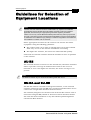
Guidelines for Selection of
Equipment Locations
NOTE:
Outdoor units and antennas should be installed ONLY by experienced installation
professionals who are familiar with local building and safety codes and, wherever
applicable, are licensed by the appropriate government regulatory authorities.
Failure to do so may void the BreezeACCESS product warranty and may expose the
end user or the service provider to legal and financial liabilities. Alvarion and its resellers
or distributors are not liable for injury, damage or violation of regulations associated with
the installation of outdoor units or antennas.
Select appropriate locations for the outdoor unit and for the indoor
equipment using the following guidelines:
The outdoor unit can be pole or wall mounted. Its location should
allow easy access to the unit for installation and testing.
The higher the antenna, the better the achievable link quality.
Units with an external antenna should be installed as near as possible
to the antenna.
AU-RE
The external antenna connected to the AU-RE unit, should be installed
where it provides coverage of all Subscriber Units in the area it is
intended to serve. The higher the antenna, the better coverage it can
provide.
NOTE:
The distance between any two antennas should be greater than 40 cm.
SU-RA and SU-RE
The SU-RA outdoor unit with its integrated antenna, or the external
antenna connected to the SU-RE unit, should be installed where it has
a direct line of sight with the Base Station antenna.
The antenna (integrated on the front side of the SU-RA outdoor unit or
external if using SU-RE) should be directed towards the Base Station.
The unit should be installed in a way that allows optimal alignment
towards the Base Station.
BreezeACCESS Version 4.3 System Manual
BreezeACCESS Version 4.3 Installation
1-6
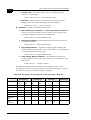
IF Cable
The outdoor unit is connected to the indoor unit by means of an IF cable
carrying signaling, control signals and power. The IF frequency is
440 MHz. The maximum allowed attenuation of the IF cable connecting
the outdoor unit to the indoor unit is 15 dB at 440 MHz, and the
maximum allowed DC resistance (the sum of the DC resistance of the
inner and outer conductors) is 1.5 ohm. This allows for cable length of
up to 30 m when using the standard RG 58 cable.
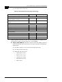
If longer cables are required, a cable with lower attenuation and/or DC
resistance should be used. Table 1-2‚ page 1-6 provides details
regarding some popular cables such as the RG 58 and RG 213. If the
spectral environment is polluted with noise in the 440 MHz band, it is
recommended to use a higher quality double-shielded cable such as the
LMR 200, LMR 240 and LMR 400 (manufactured by Times
Communications).
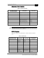
Table 1-2: IF Cables
Cable Type
RG 58
RG 213
LMR 200
LMR 240
LMR 400
Maximum cable length (m)
30
100
45
65
150
Indoor Equipment
The Indoor unit should be installed as close as possible to the point
where the IF cable enters the building. The location of the indoor unit
should also take into account the need to connect it to a power mains
outlet and to the CPE.
NOTE:
The system complies with the ETS 300 385 standard and is protected against secondary
lightning strikes when its outdoor unit is properly grounded according to the applicable
country-specific industry standards for protection of structures against lightning. The
system complies with EN 61000-4-5, test level 3 (2kV).
Manual Revision: 4.0
IF Based Equipment
1-7
Installing the Outdoor Unit
NOTE:
Outdoor units must be installed by a professional installer only.
The Outdoor Unit Bottom Panel
The SU-RA outdoor unit includes the radio and an integral high-gain
flat antenna located on the front of the unit. The SU-RE and AU-RE
outdoor radio units have an RF connector for connection to an external
antenna.
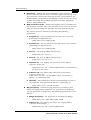
Figure 1-1: SU-RA/RE Bottom Panel
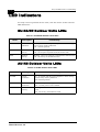
Table 1-3: SU-RA/RE LEDs
LED
Description
Functionality
ETH
Ethernet activity
Blinking – Data received from or transmitted to Ethernet
LAN
Off – No activity on the Ethernet LAN
WLNK
Wireless link
activity
Blinking – Receiving packet from the wireless link
Off – No reception of packets from the wireless link
ALARM
Alarm indication
On – A problem with the power amplifier or in the locking
process of any of the synthesizers
Off – Normal operation
BreezeACCESS Version 4.3 System Manual
BreezeACCESS Version 4.3 Installation
1-8
Table 1-4: SU-RA/RE Bar Display Description
LED
Description
Functionality
Yellow LED
Power
On – power is present
Off – power is not received from the
indoor unit
8 Green LEDs
Received signal strength
indication
Received RF signal level indication in
4 dB resolution, starting from –91
dBm
Red LED
High RF signal level
Received signal level is
–40 dBm or higher
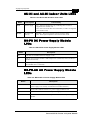
Figure 1-2: AU-RE Bottom Panel
Table 1-5: AU-RE LEDs
LED
Description
Functionality
ETH
Ethernet activity
Blinking – Data received from or transmitted to Ethernet
LAN
Off – No activity on the Ethernet LAN
12V IN
Power
On – 12 VDC power is supplied to the unit
Off – 12 VDC power is not available
ALARM
Alarm indication
On – A problem with the power amplifier or in the locking
process of any of the synthesizers
Off – Normal operation
Manual Revision: 4.0
IF Based Equipment
1-9
Pole Mounting the Outdoor Unit
The outdoor unit can be secured to the pole using one of the following
options:
Special brackets and open-ended bolts (supplied with each unit).
There are two pairs of threaded holes on the back of the unit,
allowing use of the special brackets with various pole widths.
Metal bands (9/16" wide, minimum 12" long).
Figure 1-3‚ page 1-10 shows the locations of the band grooves and
threaded holes on the rear side of the outdoor unit.
Figure 1-4‚ page 1-10 illustrates the method of installing an outdoor
unit on a pole, using the brackets and open-ended bolts.
NOTE:
Make sure to install the unit with the bottom panel (the panel with the IF connector)
facing downward.
BreezeACCESS Version 4.3 System Manual
BreezeACCESS Version 4.3 Installation
1-10
Figure 1-3: Grooves/Threaded Holes
Figure 1-4: 3" Pole Mounting Installation Using the Special Brackets
NOTE:
When inserting the open-ended bolts, make sure to insert them with the grooves
pointing outwards; these grooves are intended to allow fastening of the bolts with a
screwdriver.
Manual Revision: 4.0
IF Based Equipment
1-11
Connecting the Antenna Cable
(SU-RE and AU-RE)
Connect an RF cable between the ANT connector (located on the top
panel of the unit) and the antenna.
Connecting the Ground and IF Cables
The ground terminal (marked ) and the IF cable connector (marked IF)
are located on the bottom panel of the unit.
1. Connect one end of the ground cable to the ground terminal and tighten the
ground screw firmly. Connect the other end of the ground cable to a
protective ground connection.
2. Connect the coaxial cable to the IF connector. Verify that the length of the
IF cable is sufficient and that it can easily reach the indoor unit.
NOTE:
Make sure to switch off the power at the indoor unit prior to connecting/disconnecting
the IF cable to/from the outdoor unit.
BreezeACCESS Version 4.3 System Manual
BreezeACCESS Version 4.3 Installation
1-12
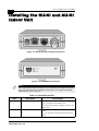
Installing the SU-NI and AU-NI
Indoor Unit
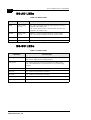
Figure 1-5: SU-NI with Voice Support Rear Panel
Figure 1-6: SU-NI/AU-NI Front Panel
NOTE:
The rear panel pictured above in Figure 1-5 is a SU-NI with voice support; AU-NI units
and SU-NI units that belong to Subscriber Units without voice support are identical,
except that they have no TEL port.
Table 1-6: SU-NI/AU-NI LEDs
LED
Description
Functionality
PWR
Power Supply
On – After successful power up, indicating that 12
VDC is supplied to the outdoor unit.
Off – Power off or failure to supply 12 VDC to the
outdoor unit.
WLNK
Wireless Link Activity
Blinking – Receiving packets from the wireless
media
Off – No reception of packets from the wireless
media
Manual Revision: 4.0
IF Based Equipment
1-13
The SU-NI/AU-NI provides the following interfaces:
An Ethernet connector (marked ETH) for connecting the unit to the
network. See Table 1-1‚ page 1-4 for information on the required
type of Ethernet cable.
An IF connector for connecting the unit to an outdoor unit.
A DC-12V connector for the power supply.
A MON connector for connecting an ASCII terminal with terminal
emulation software for configuration and maintenance purposes.
A TEL connector (Sunscriber Units with voice support only) for
connecting a regular telephone.
Installing the SU-NI/AU-NI Unit
1. Place the unit in an appropriate location on a shelf or a table. The unit can be
wall mounted using the installation materials provided with the unit. Use a 6
mm (1/4") drill and the supplied template plate for easy and accurate marking
of the holes.
2. Connect the power supply DC power cord to the DC In jack (marked
DC-12V) located on the rear panel of the unit
(shown in Figure 1-5‚ page 1-12).
3. Connect the IF cable to the IF connector (marked IF). The other side of the
IF cable should already be connected to the outdoor unit.
NOTE:
In order to avoid inadvertantly transmitting on incorrect frequencies, the basic
parameters of the unit should be configured before connecting the antenna.
4. Connect the mains power cord to the power supply unit. Connect the mains
power plug to a mains power outlet.
5. Verify that the Power LED (marked PWR) located on the front panel of the
unit, as shown in Figure 1-6‚ page 1-12, is lit.
BreezeACCESS Version 4.3 System Manual
BreezeACCESS Version 4.3 Installation
1-14
Installing Modular Base
Station Equipment
BS-SH Slot Assignments
The base station chassis has ten slots.
Figure 1-7: BS-SH Chassis Slot Assignments
The two wide slots on both sides of the shelf accommodate the BS-PS or
BS-PS-AC power supply modules. The shelf is designed to support
power supply redundancy through the use of two power supply
modules. If a single power supply is used, it can be inserted in any of
the two available slots. When using two power supply modules, both
modules must be the same type (either both BS-PS or both BS-PS-AC).
The remaining eight slots can accommodate up to six active BS-AU
modules. Two extra slots are for an optional BS-GU GPS module and/or
for future use. BS-AU and BS-GU modules can be installed in any of the
eight slots. Unused slots should be covered by blank panels.
Manual Revision: 4.0
IF Based Equipment
1-15
The BS-PS
The BS-PS provides power to all the modules installed in the BS-SH
chassis. The BS-PS front panel is shown in Figure 1-8‚ page 1-15.
Figure 1-8: BS-PS Front Panel
The BS-PS provides a power input connector (marked -48V) for
connecting the -48VDC power source to the module. The color codes of
the cable wires are:
Black
Red
-48 VDC
+ (Return)
The power switch turns the mains power to the power supply ON and
OFF.
Table 1-7: BS-PS LEDs
LED
Description
ON
-48 VDC is available and power supply is on
5V
The 5V power supply module is OK and power is consumed (at least one BS-AU
module is inserted)
12V
The 12V power supply module is OK and power is consumed (at least one
AU-RA/RE unit is connected)
BreezeACCESS Version 4.3 System Manual
BreezeACCESS Version 4.3 Installation
1-16
The BS-PS-AC
The BS-PS-AC is an AC to DC converter that provides power to all the
modules installed in the BS-SH chassis. The BS-PS-AC front panel is
shown in Figure 1-9‚ page 1-16.
Figure 1-9: BS-PS-AC Front Panel
The BS-PS-AC provides a power input connector (marked AC IN) for
connecting the AC power cable to the mains.
The ON/OFF power switch controls the connection of the mains power
to an AC to DC converter.
Table 1-8: BS-PS-AC LEDs
LED
Description
3.3V
Green LED. Indicates that the 3.3V power supply module is OK (3.3V power
supply is not used by current BreezeACCESS modules)
5V
Green LED. Indicates that the 5V power supply module is OK
12V
Green LED. Indicates that the 12V power supply module is OK
OVER TEMP
Red LED. Indicates an Over Temperature condition in the power supply module
NOTE:
If the Over Temp indication stays on for more than 10 seconds, the power supply
module will shut itself offautomatically to prevent damage.
Manual Revision: 4.0
IF Based Equipment
1-17
WARNING:
If two power supply modules are used in the same chassis for redundancy, both power
supplies must be of the same type. Do not use a mix of AC and DC power supply
modules in the same chassis.
The BS-AU
Figure 1-10: BS-AU Front Panel
Table 1-9: BS-AU LEDs
Name
Description
Functionality
PWR
Power supply
12 VDC
On – After successful power up, indicating that
12 VDC is supplied to the outdoor unit.
Off – Power off or DC/DC converter failure
(12 VDC not supplied to the outdoor unit)
WLNK
Wireless link activity
Blinking – Receiving packets from the
wireless media
Off – No reception of packets from the
wireless media
ALRM
Alarm
On – Loss of hopping synchronization (in
Slave mode)
MASTER
Master unit
On – The unit is configured as Master
BreezeACCESS Version 4.3 System Manual
BreezeACCESS Version 4.3 Installation
1-18
The BS-AU provides the following interfaces:
An Ethernet connector (marked ETH) for connecting the BS-AU to
the network. A straight Ethernet cable should be used to connect
the module to a hub, router or switch.
An IF connector for connecting the BS-AU to an outdoor unit
(AU-RE).
A MON connector for connecting an ASCII terminal with terminal
emulation software for configuration and maintenance purposes.
The switch on the BS-AU front panel controls the supply of 12 VDC
power to the outdoor unit via the IF cable. The momentary RESET
position of this switch is for resetting the outdoor unit. In the OFF
position, power is not supplied to the outdoor unit, even when the
BS-AU unit is still on.
BS-SH Chassis and Modules
Installation Procedure
1. Install the BS-SH chassis in a 19" cabinet (or place on an appropriate
shelf/table). When mounting the BS-SH chassis on a desktop, screw on the
rubber legs shipped with the unit. To prevent over-heating, leave a free space
of at least 1 U between the upper/lower covers of the chassis and other units.
2. Connect a ground cable between the ground terminal (located on the back
panel of the BS-SH chassis) and a grounding point (or to the rack when
appropriate).
3. Carefully insert the BS-PS or BS-PS-AC Power Supply and the BS-AU
modules into their intended slots and push firmly until they are securely
locked. Before inserting the modules, verify that the switches of all BS-AU
modules are in the OFF position. Close the captive screws attached to each
module. Place blank covers over all the unused slots.
4. Connect the IF cable(s) to the connector(s) marked IF located on the front
panel(s) of the BS-AU module(s) as shown in Figure 1-10‚ page 1-17. The
other side of the IF cable should already be connected to the outdoor unit.
NOTE:
In order to avoid inadvertantly transmitting on incorrect frequencies, the basic
parameters of the unit should be configured before connecting the antenna.
5. If a BS-PS DC power supply is used, connect the DC power cable to the –
48 VDC In jack (marked –48V) located on the front panel of the BS-PS
power supply. If a redundant power supply module is installed, connect a
power cable to it as well. Connect the power cable(s) to the –48 VDC
Manual Revision: 4.0
IF Based Equipment
1-19
power source and the black wire to the
-48 VDC contact of the power source. Connect the red wire to the
+ (Return) contact. Connect the shield to the ground.
6. If a BS-PS-AC AC power supply is used, connect the AC power cable to
the AC jack (marked AC IN) located on the front panel of the BS-PS-AC
power supply. If a redundant power supply module is installed, connect a
power cable to that unit as well. Connect the power cable(s) to the AC
mains.
7. Switch the BS-PS or BS-PS-AC power supplies to ON. Verify that all the
power indicator LEDs on the front panel are on. If you are using a
BS-PS-AC power supply module, verify that the OVERTEMP alarm
indicator is off.
8. Configure the basic parameters in all BS-AU modules as described in
Book 3: Commissioning. Set the switches on the front panel of all BS-AU
modules in the chassis to ON only after all the basic parameters have been
configured properly. This is to avoid transmitting at undesired frequencies.
NOTE:
Disconnect the IF cable from the BS-AU module before inserting or removing it to/from
the BS-SH chassis.
BreezeACCESS Version 4.3 System Manual
BreezeACCESS Version 4.3 Installation
1-20
Installing the GU-A-BS GPS
and Alarms System
BS-GU Front Panel
Figure 1-11: BS-GU Front Panel
Manual Revision: 4.0
IF Based Equipment
1-21
Table 1-10: BS-GU Connectors
Connector Name
Functionality
SYNC IN
Receives signals from the GPS antenna unit.
If more than one collocated BS-GU module is daisy-chained, this
connector is used by a “Slave” module to receive signals from the
“Master” module’s SYNC OUT connector.
SYNC OUT
Transfers the signals received on the SYNC IN port.
If the module is a “Master” operating in “local” mode, the internally
generated synchronization signals are also transferred to the “Slave”
via this connector.S
AL IN
Four connections to receive indications from external devices.
AL OUT
Three relay outputs to external devices.
ETH
Ethernet 10BaseT interface. Use a straight cable to connect directly to
a PC. Use a crossed cable to connect to a hub.
Table 1-11: BS-GU LEDs and Switches
LED Name
Functionality
LED Name
Functionality
PWR (green)
On – Power supply functioning properly.
Off – Power supply not functioning properly.
OK (green)
On – Proper signals are being received from the GPS antenna.
Off – The GPS antenna is not connected or it is not functioning
properly.
A1 (red)
On – Alarm In 1 (external) is activated.
A2 (red)
On – Alarm In 2 (external) is activated.
A3 (red)
On – Alarm In 3 (external) is activated.
A4 (red)
On – Alarm In 4 (external) is activated.
A5, A6 (red)
Reserved for future use.
Ethernet Activity -Ethernet
Connector embedded LED
(green)
On – Receiving traffic on the Ethernet port.
Off – No activity on the Ethernet port.
Ethernet Integrity -Ethernet On – Unit is connected to an Ethernet segment.
Connector Embedded LED Off – Unit is not connected to an Ethernet segment.
(orange)
Reset
Press this button with a paper clip or similar object in order to reset
the unit.
BreezeACCESS Version 4.3 System Manual
BreezeACCESS Version 4.3 Installation
1-22
Installing the GU-RA GPS Antenna
1. Screw the GPS antenna firmly to the special 1” threaded pole.
2. Use the mounting kit supplied with the unit (or any other suitable means)
to secure the GPS antenna pole to an existing pole (e.g. any pole used for
mounting base station antennas or the outdoor units of the BreezeACCESS
Access Units). Choose the location to ensure an obstacle-free line of sight
from the GPS antenna to the sky, extending at least 30 degrees in all
directions.
Figure 1-12: GPS Installation
3. Secure the GPS cable to the mounting pole, leaving a free length of cable
(with the 12-pin round connector at the end) sufficient for connecting to the
antenna module.
WARNING:
The cable is very heavy and connecting it to the antenna without first securing it to the
pole may damage the connector.
Manual Revision: 4.0
IF Based Equipment
1-23
4. Connect the 12-pin round connector to the GPS antenna.
5. Route the cable to the location intended for installation of the BS-GU
module.
NOTE:
Outdoor units and antennas should be installed ONLY by experienced installation
professionals who are familiar with local building and safety codes and, wherever
applicable, are licensed by the appropriate government regulatory authorities.
Failure to do so may void the BreezeACCESS product warranty and may expose the
end user or the service provider to legal and financial liabilities. Alvarion and its resellers
or distributors are not liable for injury, damage or violation of regulations associated with
the installation of outdoor units or antennas.
Installing the BS-GU module
NOTE:
When adding the BS-GU to an active base station, it is recommended to start by
reconfiguring the AU previously defined as Master to Slave, then immediately inserting
and configuring the Number of Hopping Frequencies parameter in the BS-GU
module. Otherwise both the Master AU and the BS-GU will send conflicting
synchronization signals to the Slave AUs. During this process, connectivity with the
Subscriber Units will be interrupted. It is recommended to perform the upgrade during a
planned downtime or at a time of minimal traffic. Properly configuring the value of the
Number of Hopping Frequencies parameter in the BS-GU is mandatory for proper
operation of the base station. All other parameters of the BS-GU module may be
configured later as they do not impact the operation of the system.
Inserting the BS-GU Module and Connecting
It to the Antenna
1. Carefully insert the BS-GU module into any of the free suitable slots in the
BS-SH chassis and push firmly until it is securely locked. Close the captive
screws attached to the module.
2. Connect the 9-pin micro D-Type connector of the GPS cable to the
SYNC IN connector (the top-left connector) of the BS-GU module.
WARNING:
Deactivate the power to the BS-GU unit before connecting it to a GPS antenna. Switch
on the BS-GU only after the GPS antenna has been connected.
Daisy-chaining Two or More BS-GU
Modules
If two or more BS-GU modules are installed in different collocated
BS-SH chassis, use a synchronization cable (supplied separately) to
connect the SYNC OUT connector of the first (Master) module to the
SYNC IN connector of the second module. The SYNC OUT of this second
module may be connected to the SYNC IN of a third module, and so on.
BreezeACCESS Version 4.3 System Manual
1-24
Manual Revision: 4.0
BreezeACCESS Version 4.3 Installation
BreezeACCESS V
Version 4.3
Revision 4.0
System Manual Book 3:
Commissioning
Commissioning
Table of Contents
Setting Basic Parameters .......................................1-1
Accessing the Monitor Program ..............................................1-2
Accessing the Monitor Program using
the RS 232 MON Connector ..............................................1-2
Accessing the Monitor Program using Telnet .....................1-3
Operating the Monitor Program ..........................................1-4
Configuring Basic Parameters in Access
and Subscriber Units .................................................................1-5
Configuring Parameters in GU-A-BS Units .............................1-7
Introduction .........................................................................1-7
Optimizing the Wireless Link ...................................2-1
Configuring the Maximum Data Rate (Subscriber Units) ....2-2
Aligning the Antenna of the SU-A/E Subscriber Unit .............2-3
BS-GU Connectors ...................................................3-1
Connecting External Devices to the BS-GU AL IN
and/or AL OUT Connectors ......................................................3-2
Alarms In Cable ..................................................................3-2
Alarms Out Cable ...............................................................3-3
GPS Cable .........................................................................3-3
SYNC Cable .......................................................................3-5
Verifying Proper Operation ......................................4-1
Verifying Connectivity ...............................................................4-2
Verifying the Ethernet Connection ......................................4-2
Verifying Data Connectivity (Subscriber Unit) ....................4-2
Verifying Telephone Connectivity
(Subscriber Units with Voice support) ................................4-2
Verifying Proper Operation of the GU-A-BS GPS Unit .......4-3
LED Indicators ...........................................................................4-4
SU-RA/RE Outdoor Units LEDs .........................................4-4
AU-RE Outdoor Units LEDs ...............................................4-4
SU-NI and AU-NI Indoor Units LEDs ..................................4-5
BS-PS DC Power Supply Module LEDs .............................4-5
BS-PS-AC AC Power Supply Module LEDs .......................4-5
ii
BreezeACCESS Version 4.3 Commissioning
BS-AU LEDs ...................................................................... 4-6
BS-GU LEDs ...................................................................... 4-6
Chapter 1
Setting
Basic Parameters
About This Chapter
This chapter explains how to configure the basic parameters of the
BreezeACCESS system and includes the following section:
Accessing the Monitor Program‚ page 1-2, explains how to
accessyour BreezeACCESS units for configuration.
Configuring Basic Parameters in Access and Subscriber Units‚
page 1-5, outlines the basic configuration process for
BreezeACCESS AU and SUs.
Configuring Parameters in GU-A-BS Units‚ page 1-7, outlines the
basic configuration process for BreezeACCESS BS-GU units.
BreezeACCESS Version 4.3 Commissioning
1-2
Accessing the Monitor
Program
Accessing the Monitor Program
using the RS 232 MON Connector
1. Use the monitor cable to connect the MON connector of the unit to the COM
port of your ASCII ANSI terminal or PC. The COM port connector on the
monitor cable is a 9-pin D-type plug.
2. Run a terminal emulation program (such as HyperTerminal™).
3. Set the communication parameters as follows:
Baud Rate
9600
Data Bits
8
Stop Bits
1
Parity
None
Flow Control
Xon/Xoff
Connector
Connected COM port
4. Press Enter. The Select Access Level menu appears. Select the access level
according to your authorized access level. You will be requested to enter
your password. After entering the correct password, press Enter.
Table 1-1‚ page 1-2 lists the default passwords for each of the access
levels.
Table 1-1: Default Passwords
Access Rights
Password
Read Only
public
Installer
user
Administrator
private
NOTE:
Following three unsuccessful login attempts (using incorrect passwords) from either the
monitor port or via Telnet, the monitor program will be blocked for five minutes. To
access the monitor program during this time, the unit must be reset (via SNMP or by
disconnecting/reconnecting power).
Manual Revision: 4.0
Setting Basic Parameters
1-3
BreezeACCESS/AU-BS
Official Release Version – 4.0.40
Release Date: Thu Dec 20 20:21:36 2001
Main Menu
=====================
1 – Info Screens
2 – Unit Control
3 – Basic Configuration
4 – Site Survey
5 – Advanced Configuration
X – Exit
>>>
Figure 1-1: Main Menu – Administrator Access Rights (SU and AU)
The appearance of the Main Menu varies in accordance with the set
access level.
For users with Read Only access rights, only the Info Screens option
is displayed. Users with this access level cannot access the Unit
Control, Basic Configuration, Site Survey and Advanced
Configuration menus.
For users with Installer access rights, the first four menu items (Info
Screens, Unit Control, Basic Configuration and Site Survey) are
displayed. Users with this access level cannot access the Advanced
Configuration menu.
For users with Administrator access rights, the full Main Menu will
be displayed. These users can access all the menu items.
NOTE:
The Main Menu of the BS-GU (GPS and Alarms module) does not include the Basic
Configuration option.
Accessing the Monitor Program
using Telnet
1. Connect a PC to the Ethernet port of the unit. See the table below to
determine the type of cable. Configure the PC’s IP parameters to enable
connectivity with the unit (the default IP Address is 10.0.0.1). Run the Telnet
application.
BreezeACCESS Version 4.3 System Manual
BreezeACCESS Version 4.3 Commissioning
1-4
Table 1-2: Required Type of Ethernet Cable
Unit Type
Connection to a
PC
Connection to a
Hub
Subscriber Units
Straight
Crossed
Access Units
Crossed
Straight
GPS module
Straight
Crossed
2. The Select Access Level menu appears. Select the access level according to
your authorized access rights. You will be requested to enter your
password. After entering the correct password press Enter. Default
passwords are listed in Table 1-1‚ page 1-2.
3. The Main Menu appears. Proceed as you would after connecting via the
MON port.
Operating the Monitor Program
1. Type an option number to open/activate the option. You may need to press
Enter in some cases.
2. Press Esc to exit a menu or option.
3. You can log-out and exit the monitor program from the Main Menu by
selecting X (exit). (To get to the Main Menu from anywhere in the program,
press the Esc key several times). You can also exit the monitor program
from anywhere in the program by simultaneously pressing the Ctrl and X
keys.
NOTE:
The program will terminate automatically after a given period of inactivity specified by
the Log-Out Timer parameter.
4. Reset the unit after making configuration changes for the new values to take
effect.
Manual Revision: 4.0
Setting Basic Parameters
1-5
Configuring Basic Parameters
in Access and Subscriber
Units
The Basic Configuration menu in the Monitor program includes all the
parameters necessary for the initial operation of BreezeACCESS
Subscriber and Access Units. In many installations, most of these
parameters should not be changed from their default values. The
following list includes the basic parameters and their default values:
Table 1-3: Subscriber and Access Units Basic Parameters:
Parameter
Default Value
IP Address
10.0.0.1
Subnet Mask
255.0.0.0
Default Gateway Address
0.0.0.0
DHCP Option
Disable
Access to DHCP
AU: From Ethernet Only
SU: From Wlan Only
Hopping Band
(5.7 GHz Products only)
ISM US FCC
Frequency Offset
(5.7 GHz products in ISM US
FCC or ISM international mode
only)
0
Comment
In some units this parameter
cannot be changed for
compliance with local
regulations
Flexible Hopping Definition –
Add/Remove Frequencies
In 5.7 GHz products,
applicable only if Hopping Band
is set to “Flexible Hopping
Definition”.
Scrambling Mode
Standard Scrambling
Manual Sequence Definition
None
Applicable only if Scrambling
Mode is set to Manual
Scrambling
Spanning Factor (AU)
1
Applicable only if Scrambling
Mode is set to Enhanced
Scrambling
Hopping Shift (AU)
1
BreezeACCESS Version 4.3 System Manual
BreezeACCESS Version 4.3 Commissioning
1-6
Parameter
Default Value
Hopping Sync
(AU-BS only)
Idle
Transmit Power Control
7
ATPC Option
AU: Disable
SU: Enable
Receive Attenuation Control
(SU)
0
Scanning Mode (SU)
Active
ESSID
ESSID1
Operator ESSID Option (AU)
Enable
Operator ESSID (AU)
ESSID1
Best AU Support (SU)
Disable
Preferred AU MAC Address
(SU)
00-00-00-00-00-00 (none)
VLAN Link Type
Hybrid Link
VLAN ID – Management
65535
Authentication Algorithm
Open System
Default Key ID (SU)
1
WEP Key 1-4
0000000000 (none)
Comment
1. Cannot be changed in
BreezeACCESS 5.7 GHz units
configured to Hopping Band
ISM US FCC.
2. If synchronization without
GPS is to be supported, one AU
should be configured to Master,
all other AUs should be
configured to Slave.
3. When GPS is used for
synchronization, all AUs should
be configured to Slave.
Applicable only when Best AU
Support is enabled
In the SU, can be changed to
Shared Key only after
configuring the WEP Key and
the applicable Default Key ID. In
the AU at least one WEP key
must be configured.
Once the basic parameters are configured, the unit must be reset in
order to activate the new configuration.
Manual Revision: 4.0
Setting Basic Parameters
1-7
Configuring Parameters in
GU-A-BS Units
Introduction
This section describes all the parameters that are necessary for the
initial installation and operation of GU-A-BS units. Once the unit is
properly installed and operational, other parameters can be configured
using the monitor program via Telnet or SNMP management.
NOTE:
The BS-GU does not have an external MON port, and therefore must be configured
using Telnet.
Since all the parameters needed are found in the Advanced
Configuration menu, Administrator level access is required in order to
configure a GU-A-BS unit.
Refer to Book 4: Operation and Administration for detailed information
on the applicable parameters.
In many installations, most of these parameters should not be changed
from their default values. The following list includes the basic
parameters and their default values:
Table 1-6: GU-A-BS Units Basic Parameters
Parameter
Default Value
IP Address
10.0.0.1
Subnet Mask
255.0.0.0
Default Gateway Address
0.0.0.0
DHCP Option
Disable
Number of Hopping
Frequencies
Comment
According to the Number of
Hopping Frequencies in the AUs
Automatic Recovery Option
Disable
VLAN ID – Management
65535
Not Applicable to “slave”
modules.
Once the basic parameters are configured, the unit must be reset in
order to activate the new configuration.
BreezeACCESS Version 4.3 System Manual
1-8
Manual Revision: 4.0
BreezeACCESS Version 4.3 Commissioning
Chapter 2
Optimizing
the Wireless Link
About This Chapter
This chapter explains how to optimize the performance of the wireless
link of BreezeACCESS Subscriber Units and includes the following
sections:
Configuring the Maximum Data Rate (Subscriber Units)‚
page 2-2, explains how to read the RSSI measurement and to
configure the optimum value for the Maximum Data Rate parameter.
Aligning the Antenna of the SU-A/E Subscriber Unit‚ page 2-3,
gives tips and instructions for aligning the antenna of the SU-A/E
for optimum performance.
BreezeACCESS Version 4.3 Commissioning
2-2
Configuring the Maximum
Data Rate (Subscriber Units)
The BreezeACCESS units transmit at data rates of 3 Mbps, 2 Mbps and
1Mbps. If the quality of the link is not sufficient, it is recommended to
decrease the value of the Maximum Data Rate. Note that the higher the
data rate, the higher the error rate.
Before reaching a decision on the optimum value for the Maximum Data
rate for a specific SU, it is recommended to acquire the RSSI results
from the AU. These indicate the level at which the AU receives
transmissions from the specific SU (uplink RSSI).
The per SU uplink RSSI can be viewed at the AU as follows:
1. From the Main Menu, select Site Survey.
2. In the MAC Address Database submenu, select the Display Association
Info option.
If the installer cannot access the AU (e.g. using Telnet) and cannot
obtain the measurements from the system administrator, the link
quality can be estimated based on the RSSI measurement in the SU as
follows:
1. From the Main Menu, select Site Survey.
2. Select the Continuous Link Quality Display option.
Using the assumption that the link is more or less symmetrical,
this value is a good indication to the level at which the SU is
received by the AU.
Once the RSSI results have been obtained, proceed as follows:
1. If the measured RSSI is less than a certain threshold, it is
recommended to decrease the Maximum Data Rate of the SU in
accordance with the following table (including a 3 dB safety margin
above the applicable sensitivity thrshold).
Table 2-1: Maximum Data Rates and RSSI
Maximum Data
Rate
3 Mbps
2 Mbps
1 Mbps
BreezeACCESS 5.7
GHz
RSSI>-67dBm
-75dBm<RSSI<-67dBm
RSSI<-75dBm
BreezeACCESS
5.2 GHz
RSSI>-73 dBm
-81 dBm<RSSI<-73 dBm
RSSI<-81 dBm
2. Reset the unit for the new configuration to become effective.
Manual Revision: 4.0
Optimizing the Wireless Link
2-3
Aligning the Antenna of the
SU-A/E Subscriber Unit
NOTE:
Antenna alignment using the RSSI bar display is possible only after the Access Unit you
wish to associate with is operational and the basic parameters in the Subscriber Unit
were properly configured. Otherwise, the unit will not be able to synchronize and
associate with the Access Unit. As the RSSI measurement is performed on received
frames, its results are meaningless as long as the unit is not associated with an Access
Unit.
1. Verify that the outdoor unit’s Power indication is on.
2. Align the antenna (integrated into the front side of the SU-RA outdoor unit
or separate if the unit is an SU-RE) to point in the general direction of the
base station.
3. The RSSI bar display is located on the bottom panel of the outdoor unit. The
eight green RSSI LEDs are used for reading the Received Signal Strength
Indication. The higher the number of green LEDs that are on, the higher the
level of the received signal. Rotate the antenna left and/or right until you
reach the maximum RSSI reading (as many green bars lit as possible).
Make sure that at all times the front of the antenna faces the general
direction of the base station.
4. For proper operation, for 5.2 GHz units, at least two green LEDs must be
on. For 5.7 GHz units, at least three LEDs must be on. If you cannot reach
a point where at least the minimum required number of green LEDs are
on, try to improve the reception quality by placing the antenna at a higher
point or in a different location.
NOTE:
As the RSSI bar indicator is not accurate, it is recommended to use the Continuous Link
Quality Display test for more precise alignment of the antenna.
5. Firmly secure the unit (SU-RA) or the antenna to the pole.
NOTE:
In some cases (e.g., when the Subscriber Unit is very close to the Base Station), the
antenna may have to be installed at an appropriate angle, in order to ensure that it is
directed towards the base station antenna.
BreezeACCESS Version 4.3 System Manual
2-4
Manual Revision: 4.0
BreezeACCESS Version 4.3 Commissioning
Chapter 3
BS-GU Connectors
About This Chapter
This chapter explains how to connect external devices to the AL IN and
AL OUT connectors of the BS-GU module. It also includes a description
of the cable connecting the BS-GU to the GPS antenna and of the
SYNC IN/SYNC OUT connectors’ pin assignments.
BreezeACCESS Version 4.3 Commissioning
3-2
Connecting External Devices
to the BS-GU AL IN and/or AL
OUT Connectors
Open-ended cables are available from the company for connecting to the
module external alarm inputs through the AL IN connector and/or
activating external devices through the AL OUT connector. See the
tables that follow for descriptions of the connectors’ pins functionality.
For details on defining and using the alarm inputs and output, refer to
Book 4: Operation and Administration.
WARNING:
The load of the Alarm Out (AL OUT) connector should not exceed 24 V@1 A max.
Alarms In Cable
Table 3-1: Alarms In Cable
9-pin Micro D-Type
AL IN Connector
Description
Color Code
1
Alarm Input 1
Brown
2
Alarm Input 2
White
3
Alarm Input 3
Green
4
Alarm Input 4
Red
5
Not Connected
Black
6
GND
Purple
7
GND
Yellow
8
GND
Orange
9
GND
Blue
NOTE:
The other side of the cable is supplied open-ended.
Manual Revision: 4.0
Connecting External Alarm Devices
3-3
Alarms Out Cable
Table 3-2: Alarms Out Cable
9-pin Micro D-Type
AL OUT Connector
Description
Color Code
1
Relay 1 Common
Brown
2
Relay 1 Normally Closed
White
3
Relay 2 Common
Green
4
Relay 3 Common
Red
5
Relay 3 Normally Closed
Black
6
Relay 1 Normally Open
Purple
7
Relay 2 Normally Closed
Yellow
8
Relay 2 Normally Open
Orange
9
Relay 3 Normally Open
Blue
NOTE:
The other side of the cable is supplied open-ended. The cable shield is
connected to the body of the connector.
GPS Cable
Cable Type: EIA RS-422 3X2X25AWG +1X2X24 AWG FTP Shielded
cable.
Table 3-3: GPS Cable
9-pin Micro D-Type
SYNC IN Connector
Description*
12-pin Round
Connector
Color Code
1
GPS TX+
Yellow
5
2
GPS TX-
Green
4
3
GPS RX+
Red
3
4
GPS RX-
Orange
2
5
1PPS+
Brown
11
6
1PPS-
Black
12
7
DC GPS+
Blue (thick)
1
8
DC GPS-
Brown (thick)
9
9
Not connected
----
6,7,8,10
BreezeACCESS Version 4.3 System Manual
BreezeACCESS Version 4.3 Commissioning
3-4
NOTE:
*Descriptions are with respect to the BS-GU SYNC IN connector side.
Figure 3-1 shows a 9-pin Micro D-Type Connector (cable side), and
Figure 3-2 shows a 12-pin round connector.
9-pin Micro D-Type connector
Figure 3-1: 9-pin Micro D-Type Connector (cable side)
1
9
5
12-pin round connector
Figure 3-2: 12-pin Round Connector
Manual Revision: 4.0
Connecting External Alarm Devices
3-5
SYNC Cable
Cable Type: EIA RS-422 3X2X25AWG +1X2X24 AWG FTP Shielded
cable.
Table 3-4: SYNC Cable
9-pin Micro D-Type
SYNC OUT
Connector
Description
Color Code
9-pin Micro D-Type
SYNC-IN
Connector
1
GPS TX+/SYNC D+
Black
1
2
GPS TX-/SYNC D-
Brown
2
5
1PPS+/SYNC S+
Red
5
6
1PPS-/SYNC S-
Orange
6
8
DC GPS
Green
8
9
Slave
Yellow
9
3,4,7
Not connected
3,4,7
NOTE:
* Descriptions are with respect to the SYNC OUT connector side.
The SYNC cables shield is connected to the body of the micro D-Type
connectors.
BreezeACCESS Version 4.3 System Manual
3-6
Manual Revision: 4.0
BreezeACCESS Version 4.3 Commissioning
Chapter 4
Verifying
Proper Operation
About This Chapter
This chapter explains how to confirm that the BreezeACCESS system is
functioning properly and includes the following sections:
Verifying Connectivity ‚ page 4-2 , explains how to ensure that
your BreezeACCESS and the equipment connected to them are
operating properly.
LED Indicators ‚ page 4-4 , lists the LEDs found on BreezeACCESS
units and their meanings.
BreezeACCESS Version 4.3 Commissioning
4-2
Verifying Connectivity
Verifying the Ethernet Connection
Once you have connected the unit to an Ethernet outlet, verify that the
Ethernet Integrity indicator (the yellow LED embedded in the Ethernet
connector) is on, indicating that the unit is connected to an Ethernet
segment. The Ethernet Activity indicator (the green embedded LED)
should blink whenever the unit receives or transmits traffic on the
Ethernet port.
Verifying Data Connectivity
(Subscriber Unit)
From a user’s PC or from a portable PC connected to the unit, ping the
Access Unit or try to connect to the Internet.
Verifying Telephone Connectivity
(Subscriber Units with Voice
support)
To verify correct operation of the telephone, a test telephone with the
default telephony parameters and a known IP address should be
connected to the system (the location of the test telephone is determined
by the system administrator).
Perform the following steps to verify telephone connectivity:
1. Use IP dialing to call the test telephone: dial * followed by the 12-digit IP
address of the test telephone. Verify connectivity. During the conversation,
verify that the other party has your IP address.
2. After terminating the call, the other party should use the test telephone to
call your IP address and verify that the telephone, including the ringing
circuits, functions properly.
Manual Revision: 4.0
Verifying Proper Operation
4-3
Verifying Proper Operation of the
GU-A-BS GPS Unit
NOTE:
It may take up to 10 minutes from the time the GU-RA GPS antenna is powered up until
it is fully synchronized with the GPS satellite system.
When the unit is operating properly, the PWR and OK green LEDS
should be on, indicating that the BS-GU module is supplying power to
the GU-RA GPS antenna and that the GPS antenna is functioning
properly.
If the OK LED is not on, check the functionality of the GPS antenna as
follows:
1. From the Main Menu, select Info Screens.
The Info Screens menu opens.
2. From the Info Screen menu, select Show Unit Status and view the Unit
Status display. You should see one of the following messages:
UTC is available; date..; time..: This message indicates
that the GPS antenna has synchronized with the satellite system
and that the BS-GU is functioning properly. The message may
include an incorrect time and date, such as a date in 1999: this
indicates that the GPS antenna has not yet synchronized with
the GPS satellite system.
–Or–
UTC time is not available: This message indicates that the
BS-GU is not getting timing signals from the GPS antenna. If the
antenna is functioning and properly connected to the module, a
probable reason might be that the antenna has not yet
synchronized with the GPS satellite system.
BreezeACCESS Version 4.3 System Manual
BreezeACCESS Version 4.3 Commissioning
4-4
LED Indicators
To verify correct operation of the units, view the status of the relevant
LED indicators:
SU-RA/RE Outdoor Units LEDs
Table 4-1: SU-RA/RE Outdoor Units LEDs
Name
Description
Functionality
ALARM
Alarm
indication
On – A problem with the power amplifier or in the locking
process of any of the synthesizers
Off – Normal operation
WLNK
Wireless link
activity
Blinking – Receiving packet from the wireless link
Off – No reception of packets from the wireless link
ETH
Ethernet
activity
Blinking – Data received from or transmitted to Ethernet LAN
Off – No activity on the Ethernet LAN
AU-RE Outdoor Units LEDs
Table 4-2: AU-RE Outdoor Units LEDs
Name
Description
Functionality
ALARM
Alarm
indication
On – A problem with the power amplifier or in the locking
process of any of the synthesizers
Off –Normal operation
12V IN
12 VDC Power
Indication
On – 12 VDC power is supplied to the unit
Off – 12 VDC power is not available
ETH
Ethernet
activity
Blinking – Data received from or transmitted to Ethernet
LAN
Off – No activity on the Ethernet LAN
Manual Revision: 4.0
Verifying Proper Operation
4-5
SU-NI and AU-NI Indoor Units LEDs
Table 4-3: SU-NI and AU-NI Indoor Units LEDs
Name
Description
Functionality
PWR
Power supply
On – After successful power up, indicating that 12 VDC is
supplied to the outdoor unit.
Off – Power off or DC/DC converter failure (12 VDC not supplied
to the outdoor unit)
WLNK
Wireless link
activity
Blinking – Receiving packets from the wireless media
Off – No reception of packets from the wireless media
BS-PS DC Power Supply Module
LEDs
Table 4-4: BS-PS DC Power Supply Module LEDs
Name
Description
ON
-48 VDC is available and Power Supply is ON
5V
The 5V power supply module is OK and power is consumed (at least one BS-AU
module is inserted)
12V
The 12V power supply module is OK and power is consumed (at least one
AU-RA/RE unit is connected)
BS-PS-AC AC Power Supply Module
LEDs
Table 4-5: BS-PS-AC AC Power Supply Module LEDs
Name
Description
3.3V
Green LED. Indicates that the 3.3 V power supply module is OK (3.3V
power supply is not used by current BreezeACCESS modules)
5V
Green LED. Indicates that the 5 V power supply module is OK
12V
Green LED. Indicates that the 12 V power supply module is OK
OVERTEMP
Red LED. Indicates an Over Temperature condition in the power supply
module
BreezeACCESS Version 4.3 System Manual
BreezeACCESS Version 4.3 Commissioning
4-6
BS-AU LEDs
Table 4-6: BS-AU LEDs
Name
Description
Functionality
PWR
Power supply
12 VDC
On – After successful power up, indicating that 12 VDC is
supplied to the outdoor unit.
Off – Power off or DC/DC converter failure (12 VDC not
supplied to the outdoor unit)
WLNK
Wireless link
activity
Blinking – Receiving packets from the wireless media
Off – No reception of packets from the wireless media
ALRM
Alarm
On – Loss of hopping synchronization (in Slave mode)
MASTER
Master unit
On – The unit is configured as Master
BS-GU LEDs
Table 4-7: BS-GU LEDs
LED Name
Functionality
PWR (green)
On – Power supply functioning properly.
Off – Power supply not functioning properly.
OK (green)
On – Proper signals are being received from the GPS antenna.
Off – The GPS antenna is not connected or it is not functioning
properly.
A1 (red)
On – Alarm In 1 (external) is activated.
A2 (red)
On – Alarm In 2 (external) is activated.
A3 (red)
On – Alarm In 3 (external) is activated.
A4 (red)
On – Alarm In 4 (external) is activated.
A5, A6 (red)
Reserved for future use.
Manual Revision: 4.0
BreezeACCESS V
Version 4.3
Revision 4.0
System Manual Book 4:
Operations and Administration
Operations
and Administration
Table of Contents
Accessing the Monitor Program ..............................1-1
Accessing the Monitor Program using
the RS 232 MON Connector ......................................................1-2
Accessing the Monitor Program using Telnet ........................1-3
Operating the Monitor Program ...............................................1-4
Menus and Parameters ............................................2-1
Main Menu ..................................................................................2-2
Info Screens Menu .....................................................................2-3
Show Unit Status ................................................................2-3
Show Basic Parameters .....................................................2-5
Show Advanced Parameters ..............................................2-5
Show All Parameters ..........................................................2-5
Unit Control Menu ......................................................................2-6
Basic Configuration Menu ......................................................2-13
Site Survey Menu .....................................................................2-15
Traffic Statistics (AU and SU) ...........................................2-15
Voice Statistics (SU with Voice Support Only) .................2-18
Per Hop Statistics (AU and SU) .......................................2-18
Ping Test (AU, SU and GU) .............................................2-19
Continuous Link Quality Display (Available in SU Only) ..2-20
MAC Address Database (Available in AU Only) ...............2-20
Per-rate Counters (AU and SU) .......................................2-23
RSSI Display Option (AU and SU) ...................................2-23
ATPC Counter (AU and SU) .............................................2-23
AU Alarms (IF-based AU Only) ........................................2-24
Advanced Configuration Menu ...............................................2-36
IP Parameters (AU, SU and GU) ......................................2-36
Air Interface Parameters (AU and SU) .............................2-37
Network Management Parameters (AU, SU and GU) ......2-66
Bridge Parameters (AU, SU and GU) ...............................2-69
Performance Parameters (AU and SU) ............................2-82
ii
BreezeACCESS Version 4.3 Operations and Administration
Service Parameters (AU and SU) .................................... 2-86
RADIUS Parameters Menu (Subscriber Units only) ....... 2-90
Security Parameters (AU and SU) ................................... 2-94
Voice Parameters (Subscriber Units/Voice Support Only) 2-96
Dialing Parameters (Subscriber Units/Voice Support Only) 2-97
Telephony Signals (Subscriber Units/Voice Support Only) 2-104
Hopping Parameters (GU) ............................................. 2-110
Alarm Parameters (GU) ................................................. 2-112
Chapter 1
Accessing the
Monitor Program
About This Chapter
This chapter explains how to access the monitor program. It also
describes how to use the monitor program to set up, configure, and
manage BreezeACCESS Broadband Wireless Access system units. This
includes the Subscriber Units (SUs), Access Units (AUs) and GPS and
Alarms modules (GUs).
BreezeACCESS Version 4.3 Operations and Administration
1-2
Accessing the Monitor
Program using the RS 232
MON Connector
1. Use the monitor cable to connect the MON connector of the unit to the COM
port of your ASCII ANSI terminal or PC. The COM port connector on the
monitor cable is a 9-pin D-type plug.
NOTE:
The GU-BS GPS and Alarms module does not have an external MON port. It does have
an internal MON port that can be used in laboratory conditions (consult Alvarion
technical support for further details). It is recommended to use Telnet to access the
monitor program of the GU-BS.
2. Run a terminal emulation program (such as HyperTerminal™).
3. Set the communication parameters to the following:
Baud Rate
9600
Data Bits
8
Stop Bits
1
Parity
None
Flow Control
Xon/Xoff
Connector
Connected COM port
4. Press Enter. The Select Access Level menu appears. Select the access level
according to your authorized access level. You will be requested to enter
your password. After entering the correct password, press Enter.
Table 1-1‚ page 1-2 lists the default passwords for each of the access
levels.
Table 1-1: Default Passwords
Access Rights
Password
Read Only
public
Installer
user
Administrator
private
NOTE:
Following three unsuccessful login attempts (using incorrect passwords) from either the
monitor port or via Telnet, the monitor program will be blocked for five minutes. To
enable access to the monitor program during that time, the unit must be reset (via
SNMP or by disconnecting/reconnecting power).
Manual Revision: 4.0
Accessing the Monitor Program
1-3
Accessing the Monitor
Program using Telnet
1. Connect a PC to the Ethernet port of the unit. See the table below to
determine the type of cable. Configure the PC’s IP parameters to enable
connectivity with the unit (the default IP Address is 10.0.0.1). Run the Telnet
application.
Table 1-2: Required Type of Ethernet Cable
Connection to a
PC
Unit Type
Connection to a
Hub
Subscriber Units
Straight
Crossed
Access Units
Crossed
Straight
GPS module
Straight
Crossed
2. The Select Access Level menu appears. Select the access level according to
your authorized access level. You will be requested to enter your password.
After entering the correct password press Enter.
The Main Menu appears.
BreezeACCESS/AU-BS
Official Release Version – 4.0.40
Release Date: Thu Dec 20 20:21:36 2001
Main Menu
=====================
1 – Info Screens
2 – Unit Control
3 – Basic Configuration
4 – Site Survey
5 – Advanced Configuration
X - Exit
>>>
Figure 1-1: Main Menu – Administrator Access Rights (SU and AU)
The appearance of the Main Menu varies in accordance with the set
access level.For users with Read Only access rights, only the Info
Screens option is displayed. Users with this access level cannot
access the Unit Control, Basic Configuration, Site Survey and
Advanced Configuration menus.
BreezeACCESS Version 4.3 System Manual
BreezeACCESS Version 4.3 Operations and Administration
1-4
For users with Installer access rights, the first four menu items
(Info Screens, Unit Control, Basic Configuration and Site Survey) are
displayed. Users with this access level cannot access the Advanced
Configuration menu.
For users with Administrator access rights, the full Main Menu will
be displayed. These users can access all the menu items.
NOTE:
The Main Menu of the GU-BS (GPS and Alarms module) does not include the Basic
Configuration option.
Operating the Monitor
Program
1. Type an option number to open/activate the option. You may need to press
Enter in some cases.
2. Press Esc to exit a menu or option.
3. You can log-out and exit the monitor program from the Main Menu by
selecting X (exit). To get to the Main Menu from anywhere in the program,
press the Esc key several times. You can also exit the monitor from
anywhere in the program by simultaneously pressing the Ctrl and X keys.
NOTE:
The program will terminate automatically after a given period of inactivity specified by
the Log-Out Timer parameter.
4. Reset the unit after making configuration changes for the new values to take
effect.
NOTE:
Most parameters take effect only after the unit is reset. However, some parameters
take effect immediately (run-time configurable). Appendix D includes information on all
parameters, including which are run-time configurable.
Manual Revision: 4.0
Chapter 2
Menus
and Parameters
About This Chapter
This chapter describes the BreezeACCESS configuration menus and
parameters. It includes the following sections:
Main Menu‚ page 2-2.
Info Screens Menu‚ page 2-3.
Unit Control Menu‚ page 2-6.
Basic Configuration Menu‚ page 2-13.
Site Survey Menu‚ page 2-15.
Advanced Configuration Menu‚ page 2-36.
BreezeACCESS Version 4.3 Operations and Administration
2-2
Main Menu
From the Main Menu you can access the following menus, depending on
your access level:
Info Screens – Provides read-only display of current parameter
values. Available at all access levels.
Unit Control – Enables access to general operations such as
resetting the unit, loading the default parameters, changing
passwords and switching between software versions. Available at
the Installer and Administrator access levels.
Basic Configuration – Enables access to the set of parameters that
should be configured as a part of the installation process. These
parameters are also accessible from the Advanced Configuration
menu. Available at the Installer and Administrator access levels in
SU and AU (does not exist in GU).
Site Survey – Enables activation of certain tests and viewing of
various system counters. Available at the Installer and
Administrator access levels.
Advanced Configuration – Enables access to all system
parameters, including the parameters that are included in the Basic
Configuration menu. Available only at the Administrator access
level.
Exit – Enables log-out and exit from the monitor program. Available
at all access levels.
Manual Revision: 4.0
Menus and Parameters
2-3
Info Screens Menu
BreezeACCESS/AU-BS
Official Release Version – 4.0.40
Release Date: Thu Dec 20 21:05:08 2001
Info Screens
====================
1 – Show Unit Status
2 – Show Basic Parameters
3 – Show Advanced Parameters
S – Show All Parameters
>>>
Figure 2-1: Info Screens Menu
The Info Screens menu enables viewing of the current values of various
parameter sets. The parameter sets are identical to the main parameter
groups in the configuration menus. The user can view a specific
parameter set or can elect to view all parameters (S). This menu is
available for all access levels.
Show Unit Status
The Show Unit Status menu displays the current values of the following
parameters:
Unit Type – Identifies the unit’s function as one of the following:
Access Unit, Subscriber Unit or GPS and Alarms Module.
Unit MAC Address – Displays the unit’s unique IEEE MAC address.
Unit Hardware Version – Displays the hardware version of the unit
(the indoor module of IF based products).
Flash Type – Displays the type and size of the Flash memory.
Flash Versions
Current Version – Displays the software version that is
currently active.
Shadow Version – Displays the software version currently
defined as the shadow (backup) version.
Version After Reset – Displays the software version that will be
used after the next reset.
BreezeACCESS Version 4.3 System Manual
BreezeACCESS Version 4.3 Operations and Administration
2-4
Console Speed – Displays the speed defined in the unit for the
connected terminal, used for running the terminal emulation
program.
Number of Associations Since Last Reset – For SUs - displays the
total number of associations with any AU since the last reset,
including duplicate associations with the same AU.
For AUs - displays the number of SUs that have associated with the
AU since the last reset, including duplicate associations with the
same SU.
The following parameters appear for Subscriber Units only:
Voice Hardware Version (SU with voice support only) – Displays
the hardware version of the voice module.
Unit Status – Displays the current status of the SU. There are two
possible values:
SCANNING – The SU is searching for an AU with which to
associate.
ASSOCIATED – The SU is associated with an AU.
AU MAC Address – Displays the MAC address of the AU with which
the unit is currently associated. If the unit is not associated with
any AU, the address will be that of the IEEE broadcast address:
FF-FF-FF-FF-FF-FF.
The following parameter appears for Access Units only:
Current Number of Associations – Displays the total number of
SUs associated with this AU. This number may include units that
are not currently active, as there is no aging algorithm for
associated SUs.
NOTE:
An SU will be removed from the list of associated SUs only upon occurrence of any of
the following: (1) The AU received from another AU a SNAP frame with the SU MAC
address indicating that the SU has become associated with the other AU, or (2) The AU
has decided that the SU aged out following its failure to acknowledge a certain number
of consecutive frames transmitted to it.
Manual Revision: 4.0
Menus and Parameters
2-5
The following parameter appears for GPS Modules only:
Unit Status – Indicates the status of the GPS antenna. Either one of
the following messages may be displayed:
UTC is available; date..; time..: This message indicates
that the GPS antenna has synchronized with the satellite system
and that the BS-GU is functioning properly. The message may
include an incorrect time and date, such as a date in 1999. This
indicates that the GPS antenna has not yet synchronized with
the GPS satellites system.
–Or–
UTC time is not available: This message indicates that the
BS-GU is not getting timing signals from the GPS antenna. If the
antenna is functioning and properly connected to the module,
this may be because the antenna has not yet synchronized with
the GPS satellite system.
Show Basic Parameters
The Show Basic Parameters menu displays the current values of the
parameters included in the Basic Configuration menu
(see Basic Configuration Menu‚ page 2-13). When using Read-Only
access rights the ESSID parameters (ESSID, Operator ESSID, Run Time
ESSID and Neighboring AU ESSID) and WEP Keys are not displayed.
The display includes some additional useful read-only information such
as the Number of Hopping Frequencies in SU and AU.
Show Advanced Parameters
The Show Advanced Parameters menu enables access sub-menus that
display the current values of the parameters included in the applicable
sub-menus of the Advanced Configuration menu
(see Advanced Configuration Menu‚ page 2-36). When using Read-Only
access rights the ESSID parameters (ESSID, Operator ESSID, Run Time
ESSID and Neighboring AU ESSID in Air Interface Parameters), WEP
Keys (Security Parameters) and User Password and Shared Secret
(RADIUS Parameters) are not displayed. The display includes some
additional read-only information such as Number of Hopping
Frequencies (Air Interface Parameters).
Show All Parameters
The Show All Parameters menu displays the current values of all the
parameters included in the Advanced Configuration menu.When using
Read-Only access rights the ESSID parameters (ESSID, Operator
ESSID, Run Time ESSID and Neighboring AU ESSID in Air Interface
Parameters), WEP Keys (Security Parameters) and User Password and
Shared Secret (RADIUS Parameters) are not displayed. The display
BreezeACCESS Version 4.3 System Manual
BreezeACCESS Version 4.3 Operations and Administration
2-6
includes some additional useful read-only information such as the
Number of Hopping Frequencies (SU and AU).
Unit Control Menu
The Unit Control menu includes the following options:
Reset Unit – Resets the BreezeACCESS unit and applies any
changes made to the system parameters.
Defaults Settings – Resets the unit to a predefined set of default
parameters or to save the current configuration as Operator
Defaults. The available options are:
Set Defaults – Resets the unit to a set of default parameters.
The following options are available:
Cancel Request – Exits to the Unit Control menu without
any change.
Set Complete Factory Defaults – Available only with
Administrator access rights. Resets the unit to the set of
Alvarion’s standard default values. These are the default
values as defined in this manual for each of the parameters.
After the next reset all parameters will revert to their Factory
Defaults value, except for the parameters that are marked in
the “Complete” column of Table 2-1‚ page 2-7.
NOTE:
Activating Set Complete Factory Defaults will result in loss of connectivity.
If the unit is managed remotely, you may lose the ability to communicate
with it.
Set Partial Factory Defaults – Reverts all parameters to the
values of the Factory Defaults configuration after the next
reset, except for parameters that are necessary to maintain
connectivity and to enable management of the unit and some
other sensitive parameters. The exact list of parameters that
are not changed depends on the access rights of the user.
Referring to Table 2-1‚ page 2-7, the parameters that are
not changed after activating Set Partial Factory
Defaults using Administrator access rights are marked
in the “Partial-Admin” Column. The parameters that are
not changed after activating Set Partial Factory
Defaults using Installer access rights are marked in the
“Partial-Installer” Column.
Manual Revision: 4.0
Menus and Parameters
2-7
Table 2-1: Parameters not changed after Set Complete/Partial Factory Defaults
Parameter
Complete
Partial –
Admin
Partial Installer
Unit Control Parameters
√
Passwords
√
√
Event Log Policy
√
Auto Configuration Option
√
IP Parameters
IP Address
√
√
Subnet Mask
√
√
Default Gateway Address
√
√
DHCP Option
√
√
Access to DHCP
√
√
ESSID
√
√
Operator ESSID Option
√
√
Operator ESSID
√
√
Best AU Support
√
√
Preferred AU MAC Address
√
√
ACSE Option
√
√
Dwell Time
√
√
√
√
Hopping Shift
√
√
Hopping Sequence
√
√
Air Interface Parameters
√
Hopping Band (5.7 GHz series)
Flexible Hopping Definition (defined
frequencies)
√
√
√
Scrambling Mode
√
√
√
Manual Sequence
√
√
√
Spanning Factor
√
√
Acknowledge Delay Limit
√
√
MAC Address Black List
√
√
VLAN Link Type
√
√
VLAN ID – Data
√
√
VLAN ID – Management (or Management
& Voice)
√
√
VLAN Forwarding Support
√
√
Forwarding VLAN IDs
√
√
VLAN Parameters
BreezeACCESS Version 4.3 System Manual
BreezeACCESS Version 4.3 Operations and Administration
2-8
(Continued)
Parameter
Complete
Partial –
Admin
Partial Installer
VLAN Relaying Support
√
√
Relaying VLAN IDs
√
√
VLAN Priority – Data
√
√
VLAN Priority – Management
√
√
VLAN Priority – Voice
√
√
VLAN Priority Threshold
√
√
VLAN Priority Tag
√
√
Authentication Algorithm
√
√
Default Key ID
√
√
WEP Key 1 to 4
√
√
Security Parameters
Network Management Parameters
Access To Network Management
√
Network Management Filtering
√
Network Management IP Addresses
√
Send SNMP Traps
√
Per Trap Control (all Send Trap Parameters)
√
SNMP Traps IP destination
√
SNMP Traps Community
√
Ports Control Parameters
Ethenet Port Control
√
√
Voice Port Control
√
√
RADIUS Parameters
√
RADIUS User Name
√
RADIUS User Password
√
RADIUS Shared Secret
√
Authentication Option
√
RADIUS Server Authentication IP address
√
RADIUS Server Authentication Port
√
Accounting Option
√
RADIUS Server Accounting IP address
√
RADIUS Server Accounting Port
√
Accounting Interval
√
Manual Revision: 4.0
Menus and Parameters
2-9
Set Complete Operator Defaults – Available only with
Administrator access rights. Set the unit to its’ Operator
Defaults configuration. After the next reset, all parameters
will revert to their Operator Defaults values, except for the
parameters that are marked in the “Complete” column of
Table 2-1‚ page 2-7. Operator Defaults configuration can be
defined by the Administrator (see Save Current
Configuration As Operator Defaults below). It may also be
defined at the factory according to customer’s definition. The
default Operators Defaults configuration is the Factory
Defaults configuration.
The complete Operator Defaults Configuration file can be
downloaded/uploaded using TFTP with the SNMP Write
community string. The procedure is the same as for
downloading/uploading configuration files, except that
the extension used for the file name is .cmr.
Examples (using the default SNMP Write community
string):
To upload the configuration file using DOS based TFTP
Client to an SU whose IP address is 206.25.63.65:
tftp 206.25.63.65 put Suconf private.cmr.
To download the configuration file from the same unit:
tftp 206.25.63.65 get private.cmr Suconf
NOTE:
Activating Set Complete Operator Defaults will result in loss of connectivity.
If the unit is managed remotely, you may lose the ability to communicate with it.
Set Partial Operator Defaults – Reverts all parameters to the
values of the Operator Defaults configuration after the next
reset, except for parameters that are necessary to maintain
connectivity and to enable management of the unit and some
other sensitive parameters. The exact list of parameters that are
not changed depends on the access rights of the user.
Referring to Table 2-1‚ page 2-7, the parameters that are not
changed after activating Set Partial Operation Defaults using
Administrator access rights are marked in the “Partial-Admin”
Column. The parameters that are not changed after activating
Set Partial Operator Defaults using Installer access rights are
marked in the “Partial-Installer” Column.
Save Current Configuration As Operator Defaults – Defines
the current configuration of the unit as the Operator Defaults
configuration. This option is only available with Administrator
access rights.
Change Unit Name – Changes the name of the unit, which is also
the system name in MIB2. This name is also used as the prompt of
the monitor program menus.
Valid values: A string of up to 32 printable ASCII characters.
BreezeACCESS Version 4.3 System Manual
BreezeACCESS Version 4.3 Operations and Administration
2-10
Change Password – Changes the password(s). A user with Installer
access rights can change the passwords for Read Only and Installer
levels. A user with Administrator access rights can change the
passwords of all levels.
Valid values: A string of up to 8 printable ASCII characters.
Table 1-1‚ page 1-2 lists the default passwords for each of the access
levels.
NOTE:
The Passwords are not changed upon setting the unit to default values (either Partial
or Complete).
Flash Memory Control – Selects the active software version. The
following options are available:
Reset and Boot from Shadow Version – Activates the Shadow
(backup) software version. The unit resets automatically and
loads the shadow firmware.
Use Current Version After Reset – Defines the current version
as the one that will be activated and used after the next reset.
The flash memory can store two software versions. One version is
called Current and the other is called Shadow. New software
versions are loaded as the Shadow version. You can select the
Shadow version as the new active version by selecting Reset and
Boot from Shadow Version. However, after the next reset, the
Current version will be activated again. If you wish to continue
using the currently active version after the next reset, select Use
Current Version After Reset.
The parameters configured in the unit are not changed as a result of
downloading new software versions (unless the new version includes
additional parameters or other changes in the list of parameters).
New parameters are loaded with their default values.
Console Speed – Defines the speed at which the unit communicates
with the terminal running the terminal emulation program. This
parameter must be changed prior to changing the speed of the
terminal connected to it.
The allowed speeds are: 9600, 19200, 38400, 57600 and 115200
baud.
The default value is 9600 baud.
Log Out Timer – Enters a new Log Out Timer value. If the monitor
program is not used for the specified time, the unit will
automatically exit the monitor program.
The allowed range is 1 to 999 minutes.
The default value is 5 minutes.
Event Log Menu – Controls the event log feature. The event log is
an important debugging tool and a flash memory sector is dedicated
Manual Revision: 4.0
Menus and Parameters
2-11
for storing it. Events are classified according to their severity level:
Trace (lowest severity), Message, Warning, Error or Fatal (highest
severity).
The severity at which events are saved in the Event Log is
configurable. Events from the configured severity and higher are
saved and may be displayed upon request. Log history can be
displayed up to the full number of current active events. In the log
an event is defined as active as long as it has not been erased (a
maximum of 1000 events may be displayed). The error log may be
read using TFTP, with remote file name <SNMP Read
Community>.log (the default SNMP Read Community is public).
The Event Log Menu includes the following options:
Event Log Policy – Determines the minimal severity level. All
events whose severity is equal to or higher than the defined
severity are logged.
Valid values are: Log All (TRC) Level, Message (MSG) Level,
Warning (WRN) Level, Error (ERR) Level, Fatal (FTL) Level,
Log None.
The default selection is Fatal (FTL) Level.
Display Event Log – Displays how many events are logged and
selects the number of events to be displayed (up to 1000). The
display of each event includes the event time (elapsed time since
last reset), the severity level and a message string. The events
are displayed in descending order, with the most recent event
displayed first.
Erase Event Log – Clears the event log.
Auto Configuration Parameters – A sub-menu that contains the
parameters related to using the Auto Configuration mechanism. The
Auto Configuration mechanism is intended to simplify the
configuration process through automatic loading of a configuration
file from a TFTP server. The Auto Configuration process is based on
getting from a DHCP server the address of the TFTP server and the
name of the configuration file to be loaded. This information is used
by the unit to initiate a session with the TFTP server, requesting
transfer of the applicable configuration file. Upon completing the
process of loading the new configuration file, the unit will reset
automatically so that the new configuration will take effect.
The following conditions must be met to enable the use of the Auto
Configuration process:
a.
The DHCP Option (see page 2-37) in the unit must be
configured to either DHCP Only or Automatic mode to enable
communication with the DHCP server.
b.
The unit must be able to communicate with the DHCP server,
according to the configured option of the Access to DHCP
parameter (see page 2-37).
BreezeACCESS Version 4.3 System Manual
BreezeACCESS Version 4.3 Operations and Administration
2-12
c.
The address of the TFTP server and the proper name of the
configuration file must be configured in the DHCP server:
The Server Address should be specified in the ‘sname’ field of
the DHCP header. The code for this option is 66, and the
minimum length is 1. It must include a legal IP address, with
a maximum length of 64 characters (maximum length
includes spaces. Extra characters will be ignored).
The Configuration File Name should be specified in the ‘file’
field of the DHCP header. The code for this option is 67, and
the minimum length is 1. The maximum length is 128
characters (maximum length includes spaces. Extra
characters will be ignored).
The unit shall initiate a request for a configuration file in the
following cases (provided the DHCP Option is enabled):
a.
After power-up reset (HW reset), provided the Auto
Configuration Option is enabled.
b.
Upon enabling the Auto Configuration Option.
c.
Upon a user initiated request.
NOTE:
If the response messages from the DHCP server after the requests for TFTP Server
Name and Boot File Name do not include these options, or if invalid values have been
received, this DHCP server will not be used for automatic IP parameters assignment.
The Auto Configuration Parameters sub-menu includes the
following options:
Auto Configuration Option – To disable or enable the Auto
Configuration mechanism.
The default is Disable.
Request Auto Configuration – To initiate an Auto
Configuration process.
NOTE:
Upon completion of the Auto Configuration process the unit will reset
automatically.
Show Auto Configuration Parameters – Displays the status of
the Auto Configuration Option and the Auto Configuration
Received Status (Received/Not Received), indicating whether
an Auto Configuration File has been received.
SNMP Read ESSID – This parameter is available only under
Administrator access rights. For security reasons, the values of
some parameters, including ESSID and Run Time ESSID, can be
viewed (get) using SNMP only with the Write Community string, and
are not available with the Read Community string. When this
parameter is enabled, it allows viewing (get) the values of ESSID and
Run Time ESSID with the Read Community string as well.
Manual Revision: 4.0
Menus and Parameters
2-13
Basic Configuration Menu
The Basic Configuration menu includes all the parameters that are
necessary for the initial installation and operation of the unit. Once the
unit is properly installed and operational, other parameters can be
configured either locally using the monitor program or remotely using
Telnet, SNMP management or TFTP for loading to the unit a
pre-prepared configuration file.
For more information about the initial configuration of BreezeACCESS
units, see Book 3: Commissioning.
The Basic Configuration menu includes the following submenu
parameters:
IP Parameters
IP Address (see page 2-36)
Subnet Mask (see page 2-36)
Default Gateway Address (see page 2-36)
DHCP Client (see page 2-37)
Air Interface Parameters
ESSID (see page 2-53)
Operator ESSID Parameters (AU) (see page 2-53)
Hopping Band* (see page 2-38)
Flexible Hopping Definition* (see page 2-40)
Hopping Sync (AU-BS) (see page 2-52)
Hopping Shift (AU-BS) (see page 2-48)
Transmit Power Control (see page 2-57)
ATPC Option (see page 2-60)
Receive Attenuation Control (see page 2-63)
Best AU Parameters (SU) (see page 2-55)
Best AU Support
Preferred AU MAC Address
Maximum Data Rate (SU) (see page 2-60)
Scanning Mode (SU) (see page 2-64)
*The Hopping Band and Flexible Hopping Definition parameters are not
available in units configured in the factory to operate in ISM US FCC
hopping standard only (US Option).
BreezeACCESS Version 4.3 System Manual
BreezeACCESS Version 4.3 Operations and Administration
2-14
VLAN Parameters
VLAN ID – Management (AU and SU without voice support)
(see page 2-70)
VLAN ID – Voice & Management (SU with voice support)
(see page 2-70)
VLAN Link Type (see page 2-72)
Security Parameters
Authentication Algorithm (see page 2-94)
Default Key ID (see page 2-95)
WEP Key # 1 (see page 2-95)
WEP Key # 2 (see page 2-95)
WEP Key # 3 (see page 2-95)
WEP Key # 4 (see page 2-95)
NOTE:
All parameters in the Basic Configuration menu are also available in the appropriate
submenus of the Advanced Configuration menu.
Manual Revision: 4.0
Menus and Parameters
2-15
Site Survey Menu
The Site Survey menu provides various tests and counters for verifying
the quality of the wireless link and the proper operation of the unit.
These tests can be used to help determine where to position the units
for optimal coverage, to align antennas and to assist in troubleshooting.
Traffic Statistics (AU and SU)
The traffic statistics can be used to monitor, interpret and analyze the
wired and wireless links performance. The traffic statistics counters
display statistics concerning wireless link and Ethernet frames. The
menu includes the following options:
Display Counters – Choose this option to display the current value
of the Ethernet and Wireless Link Counters.
Reset Counters – Choose this option to reset all the counters.
Ethernet Counters
The unit receives Ethernet frames from its Ethernet port and forwards
them to its internal bridge which decides whether the frame should be
transmitted to the wireless media. Frames that were discarded by the
unit’s hardware filter are not counted by the Ethernet counters.
The unit transmits valid data frames that were received from the
wireless media to the Ethernet port, as well as some internally
generated frames (e.g. responses to management queries and pings that
reached the unit from the Ethernet port).
Total received frames via Ethernet – Displays the total number of
frames received from the Ethernet port.
Transmitted wireless to Ethernet – Displays the number of frames
transmitted by the unit to the Ethernet port. These are usually
frames that have been received from the wireless side, but also
frames generated by the unit itself.
BreezeACCESS Version 4.3 System Manual
BreezeACCESS Version 4.3 Operations and Administration
2-16
Wireless Link Counters
The unit transmits data frames received from the Ethernet port, as well
as self-generated control and wireless management frames, to the
wireless media. After transmission of a unicast frame, the unit waits for
an acknowledgement (ACK) message from the receiving unit. Some
control and wireless management frames as well as broadcast and
multicast frames that are sent to more than one unit are not
acknowledged. If an ACK is not received after a predefined time
(determined by the Acknowledge Delay Limit parameter, see
page 2-61), the unit will retransmit the frame until it receives an ACK. If
an ACK is not received before the number of retransmissions has
reached a maximum predefined number (Number of Retransmissions
parameter, see page 2-82), it stops retransmitting and drops the frames.
Total transmitted frames to wireless – Displays the number of
frames transmitted to the wireless media. The total includes one
count for each data or RTP frame (internally generated voice frame)
that was transmitted successfully (excluding retransmissions) as
well as the number of transmitted control and wireless management
frames.
If the ACSE Option (see page 2-63) is enabled, then in addition to
the total count, there are also separate counters for the total
number of data frames, voice (RTP) frames and beacon frames. The
voice frames include fax frames. This is true also for Subscriber
Units that do not support voice in cells where the ACSE Option
parameter in the AU is enabled. In this case the Voice count should
be 0.
Total transmitted unicast frames to wireless - Displays the
number of unicast frames successfully transmitted to the wireless
media, excluding retransmissions. This count is useful for
calculating the rates of retransmissions or dropped frame, since
only unicast frames are retransmitted if not acknowledged.
Total submitted frames (bridge) – Displays the total number of
data and RTP frames submitted to the bridge for transmission to the
wireless media. The count does not include control frames, wireless
management frames, and retransmissions.
In addition to the total count, there are also separate counts for
frames according to the priority queue to which they were routed
(Low, Mid, or High).
If the ACSE Option is enabled, then the Low, Mid and High counts
are for data frames only and there is an additional counter for voice
(RTP) frames. The voice frames count includes fax frames. This is
true also for Subscriber Units that do not support voice in cells
where the ACSE Option in the AU is enabled. In this case the Voice
count should be 0.
Frames dropped (too many retries) – Displays the number of
dropped frames. The frames that were retransmitted to the extent of
the maximum allowed number of retransmissions without being
acknowledged.
Manual Revision: 4.0
Menus and Parameters
2-17
If the ACSE Option is enabled, then in addition to the total count,
there are also separate counters for total number of data frames and
voice (RTP) frames. The voice frames count includes fax frames. This
is true also for Subscriber Units that do not support voice in cells
where the ACSE Option in the AU is enabled. In this case the Voice
count should be 0.
Total retransmitted frames – Displays the total number of
retransmissions of frames (counts all unsuccessful
transmissions/retransmissions).
If the ACSE Option is enabled, then in addition to the total count,
there are also separate counters for total number of Data frames
and Voice (RTP) frames. This is true also for Subscriber Units that
do not support voice in cells where the ACSE Option in the AU is
enabled. In this case the Voice count should be 0.
Total Tx errors – Displays the number of transmit errors that have
occurred. The total number of Tx errors includes transmissions that
were not acknowledged properly, transmissions that were aborted
and transmissions that were delayed for various reasons (e.g. not
enough time until the end of the current dwell period).
In addition, the following special counters are displayed to indicate
the reason for the error:
H/W: An internal hardware problem in the modem.
ABR: The transmission was aborted before completion because
of internal problems in the DSP.
CSL: The transmission was cancelled because the modem was
busy in receiving data.
ACKTOUT (Acknowledge Timeout): The frame was not
acknowledged within the time defined by the Acknowledge
Delay Limit parameter.
FAIL: There was an internal timeout in the modem.
ACKCRC: There was a CRC error in the ACK message.
RTSC: The RTS was sent but no CTS was received (RTS
collision).
EOD (End of Dwell): There was not enough time left to transmit
the message
Total received frames from wireless – Displays the total number
of frames that were received from the wireless media. The count
includes data, control and wireless management frames, including
beacons received from the AU. The count does not include frames
that were discarded internally, bad frames and duplicate frames.
Total received data frames – Displays the total number of data
frames received from the wireless media, including duplicate frames
(see Duplicate frames discarded, below). In addition to the total
count, there are also separate counts for data frames according to
the receive priority queue to which they were routed (Low or High).
BreezeACCESS Version 4.3 System Manual
BreezeACCESS Version 4.3 Operations and Administration
2-18
Bad fragments received – Displays the number of frames received
from the wireless media with errors (CRC errors).
Duplicate frames discarded – Displays the number of frames
discarded due to receiving multiple copies. If an acknowledge
message was not received by the originating unit, the same data
frame can be properly received twice (or more). Although duplicate
frames are included in all counters that count data frames, only the
first copy is forwarded to the Ethernet port.
Internally discarded MIR/CIR – Displays the number of data
frames received from the Ethernet port that were discarded by the
MIR/CIR mechanism to avoid exceeding the maximum allowed
information rate.
Voice Statistics (SU with Voice
Support Only)
The voice statistics counters display information concerning voice and
fax traffic, including T.38 redundant fax traffic. The displayed
information includes the accumulated numbers since the last reset for
transmitted and received RTP frames and bytes.
Display Counters – Displays the current value of the following voice
counters.
Voice Frames Transmitted
Voice Frames Received
Voice Bytes Transmitted
Voice Bytes Received
Reset Counters – Resets the voice counters.
Per Hop Statistics (AU and SU)
The Per Hop Statistics provide information on performance of the
wireless signal at different hopping frequencies. The Per Hop Statistics
menu includes the following options:
Display Counters – Displays the continuously updated statistics.
Reset Counters – Resets the Per Hop Statistics counters.
The Display Counters option displays various statistics for each of the
hopping frequencies. In addition, it displays some general wireless link
performance statistics.
Manual Revision: 4.0
Menus and Parameters
2-19
Hopping Statistics
Num
The number of the information row, assigned automatically and
sequentially by the program.
Freq
The hopping frequency, according to the hopping sequence.
Rx
The accumulated number of frames received at the specified frequency
since last reset.
Tx
The accumulated number of frames transmitted successfully at the
specified frequency since last reset.
RTx
The accumulated number of frames re-transmitted at the specified
frequency since last reset.
avrDBM
(avrRSSI)
The average RSSI (Received Signal Strength Indication) in dBm or
RSSI units (according to the RSSI Display Option) of all the frames
received at the specified frequency since the last reset. If no frames have
been received, the avrRSSI is NA (Not Available).
The Rx, Tx and RTx per hop counters accumulate the number of
applicable frames since last reset. The counters can also be reset using
the Reset Counters option in either the Per Hop Statistics menu or in
the Traffic Counters menu.
The general rate (Frames per second) statistics is the average rate
during the last 64 hops.
The display is continuously updated. Press any key to exit.
Ping Test (AU, SU and GU)
The Ping Test menu includes the following options:
Destination IP Address – Displays the IP address of the destination
unit for pinging. Allows entering an IP address (4 x 3 digit octets,
separated by dots).
The default IP address is 192.000.000.001.
No. of Pings – Enter the number of ping attempts per session.
The allowed range is from 0 to 9999. Select 0 for continuous
pinging.
The default value is 1.
Ping Frame Length – Enter the ping packet size.
The allowed range is from 60 to 1472 bytes.
The default value is 64 bytes.
Ping Frame Timeout – Enter the ping frame timeout, which is the
amount of time (in ms) to wait between ping attempts.
The allowed range is from 200 to 60000 ms, in increments of 200
milliseconds (200, 400, 600,……60000).
The default value is 200 ms.
BreezeACCESS Version 4.3 System Manual
BreezeACCESS Version 4.3 Operations and Administration
2-20
Start Sending – Starts transmission of ping frames.
Stop Sending – Stops the transmission of ping frames. The test will
end automatically once the number of pings that were sent has
reached the value specified in the No. of Pings parameter (described
above). The Stop Sending option can be used to end the test before
completing the specified number of pings, or if continuous pinging
was selected.
Show Ping Test Values – To display the current values of the ping
test parameters, the transmission status (sending or not), the
number of pings sent, and the number of pings received
(acknowledged frames).
Continuous Link Quality Display
(Available in SU Only)
This option displays continuously updated entries that include
information on the quality of the received signal (Received Signal
Strength Indication or RSSI). Press any key to abort the test.
Each line includes the number of Beacon frames that were received
since the last measurement (total Rx), the average RSSI in dBm or RSSI
units (according to the RSSI Display Option) for these frames
(avrDBM/avrRSSI) and the Error rate (number of retransmitted frames
in the last 100 transmitted frames).
The Error rate is meaningful only when there is traffic from the SU to
the AU. It is recommended to use the Ping Test (see page 2-19) with a
Ping Frame Length of 1472 bytes.
MAC Address Database (Available
in AU Only)
The MAC Address Database displays information on the subscriber
units associated with the AU as well as bridging (forwarding)
information. The following options are available:
Display Bridging & Association Info – Displays a list of all the
Subscriber Units and stations in the Forwarding Database of the
AU. For stations behind an SU, the SU’s MAC address is also
displayed.
Each MAC address entry is followed by a description, as follows:
Et (Ethernet): Addresses that have been learned from the
Ethernet port.
Vp (Virtual port): Addresses of the nodes behind an associated
SU. For these addresses, the address of the SU is displayed in
parenthesis.
St (Static): An associated SU. These entries also include the SW
Version of the SU.
Manual Revision: 4.0
Menus and Parameters
2-21
Sp (Special): 5 Addresses that always exist:
The MAC address of the AU (appears twice as it is learned
from both the Ethernet and the wireless ports)
Alvarion’s Multicast address (01:20:D6:00:00:01, also twice).
The system handles this address as a Broadcast address.
The Ethernet Broadcast address (FF-FF-FF-FF-FF-FF)
In addition, a summary table displays information about the
Forwarding Database (Bridging Info), the Associated Subscriber
Units Database (Association Info) and the Subscriber Units that are
currently conducting a voice call (Call Info). For each of these
databases, the displayed information includes:
The current number of entries. The number of entries in the
Bridging Info includes the Et (Ethernet) and the Vp (Virtual
ports) entries. The number of entries in the Association Info
includes the associated units.
NOTE:
There is no aging algorithm for associated SUs. An SU will be removed
from the associations database only upon occurrence of any of the following:
(1) The AU received from another AU a SNAP frame with the SU MAC
address indicating that the SU has become associated with the other AU, or
(2) The AU has decided that the SU aged out following its failure to
acknowledge a certain number of consecutive frames transmitted to it.
The aging time specified for entries in these tables (the
defaults are 300 seconds for the Bridge Aging Time, No Aging
for the Association Aging Time and 1800 seconds for the Call
Info table).
The maximum allowed number of entries for these tables
(1019 for the Bridging Info and as specified by the Maximum
Number of Associations parameter for the Association Info
and the Call Info. The default value of the Maximum
Number of Associations is 512).
Display Association Info – Displays details of the associated SUs.
Each entry in the list includes the following information:
The MAC address of the associated Subscriber Unit
The Maximum Data Rate of the SU.
The average level of RF signals received from the Subscriber
Unit.
The wireless status of the SU. There are three options:
Associated
Authenticated
Not Authenticated (a temporary status)
Refer to Table 2-2 for details on the status of the SU during the
various stages of the association process.
BreezeACCESS Version 4.3 System Manual
BreezeACCESS Version 4.3 Operations and Administration
2-22
The SW version of the SU.
Table 2-2: Association Process (Active Scanning)
Message
Direction
Status in AU
SU Scanning*
Probe Request
(including ESSID) - Scanning
SU → AU
-
Probe Response (only if correct ESSID in Probe
Request)
AU → SU
-
Authentication Request
SU → AU
Not Authenticated
Challenge Text
AU → SU
Not Authenticated
Challenge Text Encrypted
SU → AU
Not Authenticated
Authentication Successful
AU → SU
Authenticated
Association Request
SU → AU
Authenticated
Association Successful
AU → SU
Associated
ACK
SU → AU
Associated
Data Traffic
SU ↔ AU
Associated
SU Synchronized
SU Authenticated
* When passive scanning is used, the Scanning Phase is comprised of
searching for a Beacon frame with the correct ESSID.
Display CIR/MIR Info: Displays details of the CIR/MIR parameters
of the associated SUs. Each entry in the list includes the following
information:
The MAC address of the associated Subscriber Unit.
The SW version of the SU.
MIR/CIR info for the SU:
CIR Tx (SU to AU)
MIR Tx (SU to AU)
CIR Rx (AU to SU)
MIR Rx (AU to SU)
Max. Delay.
Manual Revision: 4.0
Menus and Parameters
2-23
Per-rate Counters (AU and SU)
Resets or displays the per-rate counters. The per-rate counters display
the number of frames (excluding retransmissions) transmitted since the
last reset at each of the rates (1 Mbps, 2 Mbps, 3 Mbps) and the total
number of frames that were retransmitted at each of the rates. In the
AU the information is provided for each of the associated SUs, identified
by their MAC address. The counters in the AU are reset when there is a
new association with an SU (including reassociations).
RSSI Display Option (AU and SU)
In BreezeACCESS units running SW versions 3.X and below, all
measurements of received RF signal levels are displayed using arbitrary
RSSI units. From version 4.0 onward, the conventional dBm
measurement units can be used. However, to support users that prefer
to continue using RSSI units, the RSSI Display option enables selecting
the measurement units to be used for displaying received signal level
values.
Available selections: dBm, RSSI.
Default selection: RSSI.
ATPC Counter (AU and SU)
The ATPC Counter display information related to the number of ATPC
power-up/power-down messages sent or received by the unit since last
reset.
Display Counter – Displays the current value of the ATPC Counter:
ATPC Transmitted Messages (AU only) – The number of ATPC
power-up/power-down messages that were sent by the AU since
last reset.
ATPC Received Messages (SU only) - The number of ATPC
power-up/power-down messages that were received by the SU
since last reset. This counter is displayed also in units that do
not use ATPC, since the AU sends ATPC messages to all SUs,
including SUs in which the ATPC Option is disabled.
Reset Counter – Resets the ATPC Counter.
BreezeACCESS Version 4.3 System Manual
BreezeACCESS Version 4.3 Operations and Administration
2-24
AU Alarms (IF-based AU Only)
The AU Alarms feature enables to identify and alert upon the detection
of a potential problem in the outdoor unit of the AU, or another problem
that causes significant degradation in the performance of the wireless
link.
When the AU Alarms Option is enabled, three types of tests are
performed: Traffic Statistics tests, Power tests and Associations test.
Information is gathered continuously and various calculations used for
decision making are performed each test cycle period that is defined by
the configurable Test Cycle parameter. Alarms can be generated only
after a sufficient time, defined by the configurable Learning Period
parameter, has elapsed since the last reset (or since the AU Alarm
Option was enabled).
Traffic Statistics Tests
The AU gathers traffic information that is used to calculate various
traffic statistics. The calculated statistics are used for estimating the
performance of the wireless link. The following traffic statistics rates are
calculated for each test cycle period:
a. Current Retransmission Rate - Defined as Nr/(Nt+ Nr),
Where:
Nr - Number of retransmissions during the last test cycle
period.
Nt - Number of successfully transmitted unicast frames
during the last test cycle. The minimum value of Nt+ Nr for a
meaningful test is 50 (otherwise the result is NA).
b. Current Dropped Frames Rate - Defined as Nd/Nt, where
Nd is the number of dropped frames during the last test
cycle period. Dropped frames are frames that were drooped
because they were retransmitted to the extent of the
maximum allowed number of retransmissions without being
acknowledged. The minimum value of Nt for a meaningful
test is 50 (otherwise the result is NA).
c. Current CRC Error Rate - Defined as Ncrc/(Nrx+Ncrc),
where:
Ncrc - Number of frames received with a CRC error during
the last test cycle period.
Nrx - Number of successfully received frames during the last
test cycle period.
The minimum value of Nrx+Ncrc for a meaningful test is 50
(otherwise the result is NA).
d. Current Duplicate Frames Rate - Defined as Ndup/Nrx,
where Ndup is the number of dropped frames during the last
test cycle period. The minimum value of Nrx for a meaningful
test is 50 (otherwise the result is NA).
Manual Revision: 4.0
Menus and Parameters
2-25
In addition, the Average Rate is also calculated for each of the above
traffic statistics rates, using the formula Ra(t)=[Rc*1 +Ra(t-1)*5]/6,
where:
Rc - Current Rate
Ra(t) - The new value of the Average Rate for the applicable rate.
Ra(t-1) - the previous Average Rate of the applicable rate.
For the first test cycle after reset (or after enabling the AU Alarms
Option), Ra= Rc.
For each traffic statistics type, three values can be configured:
a. Minor Alarm Threshold - The threshold for decision on a
minor severity alarm for the applicable traffic statistics type.
b. Major Alarm Threshold - The threshold for decision on a
major severity alarm for the applicable traffic statistics type.
c. Minimum Minor Alarm Delta - serves in the minor alarm
decision process, as described below.
A minor severity alarm is generated if both of the following conditions
are met:
a. The Current Rate of the applicable rate exceeds the Minor
Alarm Threshold for this traffic statistics type.
b. The Current Rate is higher than the Average Rate by at
least the value of the Minimum Minor Alarm Delta,
indicating a rapid decrease in performance.
A minor severity alarm will also be generated if the Current Rate
dropped below the applicable Major Alarm Threshold but is still higher
than the applicable Minor Alarm Threshold. (Alarm status changed
from major to minor).
A major severity alarm is generated if the Current Rate has increased
above the Major Alarm Threshold for the applicable traffic statistics
type.
Power Tests
Each test cycle, the AU transmits a multicast SNAP (Sub Network
Access Protocol) polling message to its associated SUs. The SUs must
respond to this message within a given time frame. The response
message includes the last RSSI level at which the SU receives
transmissions from the AU.
BreezeACCESS Version 4.3 System Manual
BreezeACCESS Version 4.3 Operations and Administration
2-26
Based on the RSSI information responses from the SUs, the AU
performs a calculation of the SU Rx Power Average Delta, defined as
the average difference for all SUs between the last RSSI at the SU and
the previous (one before last) RSSI. The average is calculated only for
SUs that responded to both of the last two polling message. The average
is calculated as: Σn=1-N [SURSSIn(t) - SURSSIn(t-1)]/N, where:
SURSSIn(t) - The last RSSI value received from responding
SU number n.
SURSSIn(t-1) - The previous RSSI value received from responding
SU number n.
N - The number of SUs that responded to both last and previous polling
requests.
A Tx Power Level Decrease major severity alarm is generated if the
decrease in the SU Rx Power Average Delta is higher than the value of
the configurable SU Rx Power Decrease Threshold parameter:
-(SU Rx Power Average Delta) > SU Rx Power Decrease Threshold.
The alarm is generated only if the number of SUs used in calculating the
SU Rx Power Average Delta (responded to both of the last two polling
messages) is at least 5.
NOTE:
SUs with SW version below 4.3 will respond to the polling message. However,
the last RSSI value will not be included in the response message. Therefore,
this test is not applicable to cells where all SUs use SW version below 4.3.
The AU also gathers for all responding SUs the RSSI level at which each
SU was received by the AU. Based on these measurements, the AU
performs a calculation of the AU Rx Power Average Delta, defined as
the average difference for all responding SUs between the last RSSI at
he AU and the previous (one before last) RSSI:
Σn=1-N [AURSSIn(t) - AURSSIn(t-1)]/N, where:
AURSSIn(t) - The last RSSI value at which the responding SU number n
was received by the AU.
AURSSIn(t-1) - The previous RSSI value at which the responding SU
number n was received by the AU.
An Rx Signal Strength Decrease major severity alarm is generated if
the decrease in the AU Rx Power Average Delta is higher than the
value of the configurable AU Rx Power Decrease Threshold parameter:
-(AU Rx Power Average Delta) > AU Rx Power Decrease Threshold.
The alarm is generated only if the number of responding SUs used in
calculating the AU Rx Power Average Delta (responded to both of the
last two polling messages) is at least 5.
Manual Revision: 4.0
Menus and Parameters
2-27
Association Tests
If the AU was reset 3 times because no SU became associated with it, a
No Associations critical alarm will be generated, provided that
previously the AU was associated with at least Minimum Number Of
SUs.
An All Associations Lost major alarm is generated if no response was
received by the AU to the last three polling messages, provided that
prior to that, the average number of responding SUs was not lower than
the Minimum Number Of SUs.
AU Alarms Summary
A prerequisite for all alarms except the No Associations alarm, is that
the elapsed time since last power-up (or since the AU Alarms Option
was enabled) is not lower than the Learning Period.
The AU Alarms are summarized below.
No Associations Alarm
Severity:
Critical
On Conditions:
Three consecutive resets due to no response from any SU, and
prior to that the AU was associated with at least Minimum
Number Of SUs.
Off Conditions:
a. At lease one SU became associated with the AU
-ORb. All alarms were cleared,
-ORc. AU Alarms Option was disabled
Possible Problem:
Unlocked synthesizer, very low Tx power or another major HW
problem.
BreezeACCESS Version 4.3 System Manual
BreezeACCESS Version 4.3 Operations and Administration
2-28
All Associations Lost Alarm
Severity:
Major
On Conditions:
No response from any SU to the last 3 polling messages, and
prior to that the average number of responding SUs was not
lower than the Minimum Number Of SUs.
Off Conditions:
a. At lease one SU became associated with the AU
-ORb. All alarms were cleared
-ORc. AU Alarms Option was disabled
Possible Problem:
Unlocked synthesizer, very low Tx power or another major HW
problem.
Tx Power Level Decrease Alarm
(not applicable if SUs use SW version lower than 4.3)
Severity:
Major
On Conditions:
The inverse (minus) of SU Rx Power Average Delta is higher
than SU Rx Power Decrease Threshold, and the number of
SUs that responded to the last two polling messages is at least 5.
Off Conditions:
a. All alarms were cleared
-ORb. AU Alarms Option was disabled
Possible Problem:
A transmitter fault resulting in a significant decline of the Tx
power level.
Rx Signal Strength Decrease Alarm
Severity:
Major
On Conditions:
The inverse (minus) of AU Rx Power Average Delta is higher
than AU Rx Power Decrease Threshold, and the number of
SUs that responded to the last two polling messages is at least 5.
Off Conditions:
a. All alarms were cleared,
-ORb. AU Alarms Option was disabled
Possible Problem:
Manual Revision: 4.0
A receiver fault.
Menus and Parameters
2-29
High Retransmissions Rate Alarm
Severity:
Minor, Major
On Conditions:
Minor Severity Alarm:
a. The Retransmissions Current Rate exceeds the
Retransmissions Minor Alarm Threshold, and is
higher than the Retransmissions Average Rate by at
least Retransmissions Minor Alarm Minimum Delta,
-ORb. The Retransmissions Current Rate has dropped below
the Retransmissions Major Alarm Threshold but is still
higher than the Retransmissions Minor Alarm
Threshold.
Major Severity Alarm: The Retransmissions Current Rate is
higher than the Retransmissions Major Alarm Threshold.
Off Conditions:
a. The Retransmissions Current Rate has dropped below
the Retransmissions Minor/Major Alarm Threshold,
-ORb. All alarms were cleared,
-ORc. AU Alarms Option was disabled
Possible Problem:
a. Transmitter or receiver fault
b. Poor link conditions, strong interference, or an
overloaded network.
BreezeACCESS Version 4.3 System Manual
BreezeACCESS Version 4.3 Operations and Administration
2-30
High Dropped Frames Rate Alarm
Severity:
Minor, Major
On Conditions:
Minor Severity Alarm:
a. The Dropped Frames Current Rate exceeds the Dropped
Frames Minor Alarm Threshold, and is higher than the
Dropped Frames Average Rate by at least Dropped
Frames Minor Alarm Minimum Delta,
-ORb. The Dropped Frames Current Rate has dropped below
the Dropped Frames Major Alarm Threshold, but is
still higher than the Dropped Frames Minor Alarm
Threshold.
Major Severity Alarm: The Dropped Frames Current Rate is
higher than the Dropped Frames Major Alarm Threshold.
Off Conditions:
a. The Dropped Frames Current Rate has dropped below
the Dropped Frames Minor/Major Alarm Threshold,
-ORb. All alarms were cleared
-ORc. AU Alarms Option was disabled
Possible Problem:
a. Transmitter or receiver fault
b. A severe case of poor link conditions, strong
interference, or an overloaded network.
Manual Revision: 4.0
Menus and Parameters
2-31
High CRC Error Rate Alarm
Severity:
Minor, Major
On Conditions:
Minor Severity Alarm:
a. The CRC Error Current Rate exceeds the CRC Error
Minor Alarm Threshold, and is higher than the CRC
Error Average Rate by at least CRC Error Minor
Alarm Minimum Delta,
-ORb. The CRC Error Current Rate has dropped below the
CRC Error Major Alarm Threshold but is still higher
than the CRC Error Minor Alarm Threshold.
Major Severity Alarm: The CRC Error Current Rate is
higher than the CRC Error Major Alarm Threshold.
Off Conditions:
a. The CRC Error Current Rate has dropped below the
CRC Error Minor/Major Alarm Threshold,
-ORb. All alarms were cleared,
-ORc. AU Alarms Option was disabled
Possible Problem:
a. Receiver fault
b. Strong interference
BreezeACCESS Version 4.3 System Manual
BreezeACCESS Version 4.3 Operations and Administration
2-32
High Duplicate Frames Rate Alarm
Severity:
Minor, Major
On Conditions:
Minor Severity Alarm:
a. The Duplicate Frames Current Rate exceeds the
Duplicate Frames Minor Alarm Threshold, and is
higher than the Duplicate Frames Average Rate by at
least Duplicate Frames Minor Alarm Minimum Delta,
-ORb. The Duplicate Frames Current Rate has dropped below
the Duplicate Frames Major Alarm Threshold but is
still higher than the Duplicate Frames Minor Alarm
Threshold.
Major Severity Alarm: The Duplicate Frames Current Rate
is higher than the Duplicate Frames Major Alarm Threshold.
Off Conditions:
a. The Duplicate Frames Current Rate has dropped below
the Duplicate Frames Minor/Major Alarm Threshold,
-ORb. All alarms were cleared,
-ORc. AU Alarms Option was disabled
Possible Problem:
a. Transmitter fault
b. Strong interference, preventing the SU from receiving
the AU’s ACKs.
Manual Revision: 4.0
Menus and Parameters
2-33
The AU Alarms Menu
The AU Alarms menu enables to configure relevant parameters and to
view current statistics. The AU Alarms menu is available only with
Administrator access rights, except for Show All AU Alarms
Parameters and Data that is also available with Installer access rights.
AU Alarms Option - Enables to enable or disable the AU Alarms
feature. The default is Disable.
Learning Period - Enables to define the period dedicated to
accumulating information without generating alarms (except for the
No association alarm).
Valid values: 1 to 1440 (minutes)
Default: 30 (minutes)
Test Cycle - Enables to define the time between two consecutive
transmissions of a polling message and for calculating the current
averages for the various traffic statistics.
Valid values: 1 to 1440 (minutes)
Default: 10 (minutes)
Traffic Statistics - A sub menu that includes the following options:
Retransmissions Rate Parameters
Dropped Frames Rate Parameters
CRC Error Rate Parameters
Duplicate Frames Rate Parameters
For each of these traffic statistics types, a sub menu enables to
configure three parameters:
Minor Alarm Minimum Delta - The minimum difference
between the Current Rate and the previous Average Rate,
for activating a minor severity alarm, for the relevant
statistics type. Another prerequisite for activating the alarm
is that the relevant Current Rate exceeds the applicable
Minor Alarm Threshold.
Valid range: 0 to 100 (%)
Minor Alarm Threshold - The threshold for activating a
minor severity alarm for the relevant traffic statistics type.
Another prerequisite for activating the alarm is that the
difference between the applicable Current Rate and the
previous Average Rate exceeds the Minor Alarm Minimum
Delta.
Valid range: 1 to 100 (%)
Major Alarm Threshold - The threshold for activating a
major severity alarm for the relevant statistics type.
Valid range: 1 to 100 (%)
BreezeACCESS Version 4.3 System Manual
BreezeACCESS Version 4.3 Operations and Administration
2-34
The default parameters for these alarms is as follows:
Parameter
Default (%)
Retransmission Minor Alarm Minimum Delta
20
Retransmission Minor Alarm Threshold
30
Retransmission Major Alarm Threshold
60
Dropped Frames Minor Alarm Minimum Delta
10
Dropped Frames Minor Alarm Threshold
10
Dropped Frames Major Alarm Threshold
20
CRC Error Minor Alarm Minimum Delta
20
CRC Error Minor Alarm Threshold
40
CRC Error Major Alarm Threshold
70
Duplicate Frames Minor Alarm Minimum Delta
5
Duplicate Frames Minor Alarm Threshold
5
Duplicate Frames Major Alarm Threshold
15
NOTE:
The value of the Major Alarm Threshold must be higher than the applicable
Minor Alarm Threshold. The system will not accept a Major Alarm Threshold
that is lower than the current Minor Alarm Threshold, and vice versa.
Show Traffic Statistics Parameters and Data - Displays for each
statistics type the configured parameters as well as the
applicable Current and Average Rates.
SU Rx Power Test - A sub menu that includes the following
options:
SU Rx Power Decrease Threshold - The minimum inverse
(negative) value of the SU Rx Power Average Delta that will
trigger an alarm.
Valid values: 1 to 99 (dBm).
Default value: 15 (dBm).
Show SU Rx Power Test Parameters and Data - Displays the
value of the SU Rx Power Decrease Threshold and the current
SU Rx Power Average Delta.
AU Rx Power Test - A sub menu that includes the following
options:
AU Rx Power Decrease Threshold- The minimum inverse
(negative) value of the AU Rx Power Average Delta that will
trigger an alarm.
Valid values: 1 to 99 (dBm).
Manual Revision: 4.0
Menus and Parameters
2-35
Default value: 15 (dBm).
Show AU Rx Power Test Parameters and Data - Displays the
value of the AU Rx Power Decrease Threshold and the current
AU Rx Power Average Delta.
Responding SUs - a sub menu that includes the following options:
Minimum Average Number Of SUs - Enables to define the
minimum average number of SUs required for association tests.
Valid values: 1 to 254 (SUs)
Default value: 5 (SUs)
Show Responding SUs Parameters and Data - Displays the
value of the Minimum Average Number Of Responding SUs
and the Current and Average Number Of Responding SUs.
Alarms Status - a sub menu that includes the following options:
Clear All alarms - Enable to clear (set off) all the AU Alarms.
Show Turned On Alarms - Displays a list of all the alarms that
are turned on and the severity of each of these alarms.
Show All AU Alarms Parameters and Data - Displays the values of
all AU Alarms parameters as well as all the current results available
in Show Traffic Statistics Parameters and Data, in Show SU Rx
Power Test Parameters and Data, in Show AU Rx Power Test
Parameters and Data and in Show Turned On Alarms.
BreezeACCESS Version 4.3 System Manual
BreezeACCESS Version 4.3 Operations and Administration
2-36
Advanced Configuration Menu
The Advanced Configuration menu provides access to all the
parameters, including the parameters that are available through the
Basic Configuration menu.
The Advanced Configuration menu provides access to the following
menus:
IP Parameters (AU, SU and GU) (see page 2-36)
Air Interface Parameters (AU and SU) (see page 2-37)
Network Management Parameters (AU, SU and GU) (see page 2-66)
Bridge Parameters (AU and SU) (see page 2-69)
VLAN Parameters (GU) (see page 2-69)
Performance Parameters (AU and SU) (see page 2-82)
Service Parameters (AU and SU) (see page 2-86)
RADIUS Parameters (SU) (see page 2-90)
Security Parameters (AU and SU) (see page 2-94)
Voice Parameters (SU with voice support) (see page 2-96)
Dialing Parameters (SU with voice support) (see page 2-97)
Telephony Signals Parameters (SU with voice support)
(see page 2-104)
Hopping Parameters (GU) (see page 2-110)
Alarm Parameters (GU) (see page 2-112)
IP Parameters (AU, SU and GU)
The IP Parameters sub-menu allows configuration of the following
parameters:
IP Address – Displays the current IP address of the unit and allows
the entry of a new IP address.
The default IP Address is 10.0.0.1.
Subnet Mask – Displays the current subnet mask of the unit and
allows entry of a new subnet mask.
The default mask is 255.0.0.0.
Default Gateway Address – Displays the current address of the
default gateway of the unit and allows entry of a new default
gateway address.
The default is 0.0.0.0.
Manual Revision: 4.0
Menus and Parameters
2-37
DHCP Client
DHCP Options – Displays the current status of the DHCP
(Dynamic Host Configuration Protocol) support, and allows
selecting a new operation mode. The available options are:
Disable – Use manual procedure for configuring the IP
parameters.
DHCP Only – Search for a DHCP Server and obtain the IP
parameters from it (IP Address, Subnet Mask and Default
Gateway Address).
Automatic – Search for a DHCP Server for configuration of
the IP parameters. If a DHCP Server is not found within
approximately 40 seconds, use the currently configured IP
parameters.
The default is Disable.
Access to DHCP – To define the port through which the unit is
allowed to communicate with a DHCP server. The options are:
From Wlan Only
From Ethernet Only
From Both Ethernet & WLAN
The default for an Access Unit is From Ethernet Only. The
default for a Subscriber Unit is From Wlan Only.
NOTE:
The Access to DHCP option is not available in the GU, as this module does
not have a wireless link interface.
Show IP Parameters – Displays the current values of the IP
Parameters.
Air Interface Parameters (AU and
SU)
Hopping Frequencies Setting Parameters
The process of setting the hopping sequence includes the following
steps:
a.
Select the frequencies to be used
b.
Define the method of generating the basic hopping sequence
based on the set of selected frequencies. The method of
generating the basic sequence also defines the hopping shift
mechanism for generating different actual hopping sequences.
c.
Define a different hopping sequence for each AU in order to
minimize interference between adjacent AUs.
BreezeACCESS Version 4.3 System Manual
BreezeACCESS Version 4.3 Operations and Administration
2-38
NOTE:
The same method for generating the basic hopping sequence (and the hopping shift
mechanism) should be used for all units in the system to enable SUs to communicate
with the AUs and to support radio planning that will provide minimal interference
between neighboring sectors.
The method for configuring the basic set of hopping frequencies
depends on the frequency band and on other parameters:
In products that operate in the 5.2 GHz band the hopping
frequencies are defined using the Flexible Hopping Definition
menu.
In 5.7 GHz products that are configured in the factory to
operate in ISM US FCC mode only, or when the selected
Hopping Band is either ISM US FCC or ISM International, the
Frequency Offset parameter can be used to shift the hopping
frequencies band.
In 5.7 GHz products where the Hopping Band parameters is set
to Flexible Hopping Definition, the Flexible Hopping
Definition menu is used to define the hopping frequencies.
Hopping Band – (5.7 GHz products only) - Available in units with
INT option only. Defines the method of generating the basic hopping
sequence. The available selections are ISM US FCC, ISM
International and Flexible Hopping Definition.
ISM US FCC: The basic hopping sequence is as defined in the
IEEE 802.11 standard and shown in Table 2-3. There are 79
hopping frequencies, using channels 2 to 80. (The channel
number is the distance in MHz from the beginning of the
frequency band, so that channel number 2 is at 5727MHz).
Synchronization is not supported (Hopping Sync parameter is
set to Idle and cannot be changed).
ISM International: The basic hopping sequence is as defined in
the IEEE 802.11 standard and shown in Table 2-3. There are 79
hopping frequencies, using channels 2 to 80. (The channel
number is the distance in MHz from the beginning of the
frequency band, so that channel number 2 is at 5727MHz).
Synchronization (Hopping Sync) is supported.
Flexible Hopping Definition: The Flexible Hopping Definition
menu should be used to define the basic hopping sequence.
NOTE:
In 5.7 GHz units that are configured in the factory to operate only in ISM US FCC
hopping standard (US Option), the Hopping Band menu is not available.
Manual Revision: 4.0
Menus and Parameters
2-39
Table 2-3: ISM Basic Hopping Sequence
Index
Channel
#
Frequency
(MHz)
Index
Channel
#
Frequency
(MHz)
Index
Channel
#
Frequency
(MHz)
1
2
5727
28
5
5730
55
15
5740
2
25
5750
29
39
5764
56
35
5760
3
64
5789
30
12
5737
57
67
5792
4
10
5735
31
36
5761
58
52
5777
5
45
5770
32
68
5793
59
58
5783
6
18
5743
33
9
5734
60
44
5769
7
73
5798
34
70
5795
61
50
5775
8
49
5774
35
77
5802
62
17
5742
9
21
5746
36
6
5731
63
7
5732
10
63
5788
37
62
5787
64
19
5744
11
78
5803
38
29
5754
65
8
5733
12
31
5756
39
14
5739
66
69
5794
13
61
5786
40
27
5752
67
51
5776
14
24
5749
41
16
5741
68
42
5767
15
54
5779
42
59
5784
69
3
5728
16
65
5790
43
43
5768
70
30
5755
17
28
5753
44
76
5801
71
57
5782
18
79
5804
45
34
5759
72
37
5762
19
33
5758
46
72
5797
73
55
5780
20
4
5729
47
11
5736
74
26
5751
21
20
5745
48
60
5785
75
46
5771
22
13
5738
49
80
5805
76
53
5778
23
38
5763
50
47
5772
77
40
5765
24
74
5799
51
22
5747
78
32
5757
25
56
5781
52
75
5800
79
48
5773
26
71
5796
53
66
5791
27
23
5748
54
41
5766
Frequency Offset (5.7 GHz series only) - The Frequency Offset
parameter is applicable only if the Hopping Band is either ISM US
FCC or ISM International. It has no effect in Flexible Hopping
Definition mode. The Frequency Offset defines the "shift" in MHz of
each channel in the hopping sequence relative to the frequency in
BreezeACCESS Version 4.3 System Manual
BreezeACCESS Version 4.3 Operations and Administration
2-40
the base sequence. For example, if the Frequency Offset is 10,
channel 2 will be at 5737 MHz (5727 + 10).
The permitted range in ISM US FCC is 0 to 45 (MHz). In ISM
International mode the valid range is 0 to 70 (MHz).
The default value is 0 (MHz).
Flexible Hopping Definition –Adds and removes frequencies
to/from the list of hopping frequencies; displays the selected
hopping frequencies and the current hopping sequence (based on
the previous selections made before the last reset). The new
selections will come into effect only after the next reset.
The default sequence (including the case where all frequencies were
deleted) is:
5.2 GHz series: 5153 MHz
5.7 GHz series: 5726 MHz
Add Frequencies – Adds discrete hopping frequencies or
frequency ranges. Enter a list of frequencies and/or frequency
ranges to be added. Use a comma to separate between entries
(no spaces).
5.7 GHz series: The allowed entries are from 5725 to 5850
in steps of 1 MHz.
Example: Enter 5725 - 5730, 5735 in the list to add the
frequency channels 5725, 5726, 5727, 5728, 5729, 5730
and 5735 MHz.
NOTE:
In some countries the permitted range is from 5725 to 5875 MHz..
5.2 GHz series: The available range is from 5151 to 5350
MHz using a 1 MHz grid. The minimum distance between
channels is 2 MHz.
Example 1: Adding the band 5151- 5160 is equivalent to
adding the discrete frequencies 5151, 5153, 5155, 5157 and
5159 MHz.
Example 2: Adding the band 5152 - 5160 is equivalent to
adding the discrete frequencies 5152, 5154, 5156, 5158 and
5160 MHz.
Example 3: A trial to add 5152 - 5160, 5161 will be rejected
because it does not meet the requirement for a minimum
distance of 2 MHz between channels.
Remove Frequencies - Removes frequencies from the existing
list. Enter a list of frequencies and/or frequency ranges to be
removed, using the same guidelines as in Add Frequencies
above. When a frequency range is removed, all frequencies in the
range that are included in the list of frequencies to be used, are
Manual Revision: 4.0
Menus and Parameters
2-41
removed, including the frequencies that define the range
boundaries.
Erase All – Erases all the entries from the list.
Scrambling Definition – Defines the method of organizing the
selected frequencies to form the actual hopping sequence to be
used. Proper organization of the hopping sequence is essential to
guarantee minimal cross interference among several collocated
AUs that use the same sequence with different Hopping Shift
values.
Scrambling Mode – Defines the scrambling mode. The
following options are available:
• Standard Scrambling – This mode is not recommended
for sequences with 7 or more channels. The scrambled
basic sequences for 3 to 6 frequencies when using
Standard Scrambling are:
Table 2-4: Basic Sequences using Standard Scrambling
N (number of channels)
Scrambled Basic Sequence (channel indexes)
3
1, 3, 2
4
1, 3, 2, 4
5
1, 3, 5, 2, 4
6
1, 3, 5, 2, 6, 4
•
•
Frequency 1 (index=1) is the lowest frequency in the list
of frequencies to be used, frequency 2 is the next
frequency and so on.
Manual Scrambling – For customized definition of the
hopping sequence, using the Manual Sequence
Definition option (see below).
Enhanced Scrambling – Automatically generates
hopping sequences using an enhanced algorithm. It is
recommended that Enhanced Scrambling rather then
Standard Scrambling be used. If the Enhanced
Scrambling Mode is selected, the Spanning Factor
parameter (see below) must be configured in the AU. The
Enhanced Mode is not suitable for sequences with 6 or
less frequencies. If Enhanced Scrambling is selected with
sequences that have 6 or less frequencies, than
Standard Scrambling is used by default.
The scrambled sequence is generated according to the
following rules:
a.The first channel in the basic scrambled sequence is
frequency 1 (Frequency 1 (index=1) is the lowest
frequency in the list of frequencies to be used, frequency
2 is the next frequency and so on.)
BreezeACCESS Version 4.3 System Manual
BreezeACCESS Version 4.3 Operations and Administration
2-42
b.The index of each of the other channels is calculated
by adding the Spanning Factor to the index of the
previous channel. Note that the sequence is cyclic,
meaning that adding 1 to the highest index in the
sequence (Index=N where N is the number of channels in
the sequence) will result in the first channel (Index=1).
The scrambled basic sequence can also be calculated
using the following formula:
Px (j)= {[(j-1)*X]mod(N)}+1
Where:
X is the Spanning Factor
N is the number of channels in the sequence (modulus)
J is the sequence index
Example: N=8, X=3
P1(5)={[(1-1)*3}mod8}+1=1
P2(5)={[(2-1)*3}mod8}+1=6
P3(5)={[(3-1)*3}mod8}+1=3
P4(5)={[(4-1)*3}mod8}+1=8
P5(5)={[(5-1)*3}mod8}+1=5
P6(5)={[(6-1)*3}mod8}+1=2
P7(5)={[(7-1)*3}mod8}+1=7
P8(5)={[(8-1)*3}mod8}+1=4
And the basic scrambled sequence is:
1, 4, 7, 2, 5, 8, 3, 6.
Manual Sequence Definition – Manually defines the
hopping sequence, using numbered channel indexes (from 1
to “Number of Hopping Frequencies”). The sequence length
must be equal to “Number of Hopping Frequencies” (all the
defined frequencies must be used).
Erase Manual Sequence – Erases the manually defined
hopping sequence.
Spanning Factor (AU only) – Defines the Spanning
Factor to be used by the Enhanced Scrambling
mechanism. The Spanning Factor should be chosen so
that the GCD (Greater Common Divisor) of the Spanning
Factor and the Number of Hopping Frequencies would
be 1 (e.g. for 8 frequencies possible values for the
Spanning Factor are 1, 3, 5 and 7). The SU learns the
value of the Spanning Factor from the AU during the
association process.Use of different spanning factors by
non-synchronized neighboring base stations reduces the
probability of interference between adjacent sectors.
Manual Revision: 4.0
Menus and Parameters
2-43
Valid values: 1 to Number of Hopping Frequencies minus
1, provided it meets the GCD requirement as described
above.
It is not recommended to use spanning factors of 1 and
N-1, as they result in hopping on consecutive channel
(assuming that the available channels are consecutive). In
these cases the advantage of using frequency hopping is
not fully utilized, since a narrow band interference may
affect several consecutive hops. Spanning factors of 2 and
N-2 also result in a relatively poor spread of the hopping
frequencies over the available frequency band.
Default Vale: 1
NOTE:
During the association process, the SU learns the Scrambling Mode
(and the Spanning Factor if applicable) of the AU. If the Scrambling
Mode of the AU is different from the one configured for the SU, than
after completing the association process the SU will use the
Scrambling Mode of the AU.
Table 2-5: Spanning Factors and Hopping Sequences for Sequences with 7 to 25
Channels
Channels
Spanning
Factor
Hopping Sequences
7
1
2
3
4
5
6
1, 2, 3, 4, 5, 6, 7
1, 3, 5, 7, 2, 4, 6
1, 4, 7, 3, 6, 2, 5
1, 5, 2, 6, 3, 7, 4
1, 6, 4, 2, 7, 5, 3
1, 7, 6, 5, 4, 3, 2
8
1
3
5
7
1, 2, 3, 4, 5, 6, 7, 8
1, 4, 7, 2, 5, 8, 3, 6
1, 6, 3, 8, 5, 2, 7, 4
1, 8, 7, 6, 5, 4, 3, 2
9
1
2
4
5
7
8
1, 2, 3, 4, 5, 6, 7, 8, 9
1, 3, 5, 7, 9, 2, 4, 6, 8
1, 5, 9, 4, 8, 3, 7, 2, 6
1, 6, 2, 7, 3, 8, 4, 9, 5
1, 8, 6, 4, 2, 9, 7, 5, 3
1, 9, 8, 7, 6, 5, 4, 3, 2
10
1
3
7
9
1, 2, 3, 4, 5, 6, 7, 8, 9, 10
1, 4, 7, 10, 3, 6, 9, 2, 5, 8
1, 8, 5, 2, 9, 6, 3, 10, 7, 4
1, 10, 9, 8, 7, 6, 5, 4, 3, 2
BreezeACCESS Version 4.3 System Manual
BreezeACCESS Version 4.3 Operations and Administration
2-44
Channels
Spanning
Factor
Hopping Sequences
11
1
2
3
4
5
6
7
8
9
10
1, 2, 3, 4, 5, 6, 7, 8, 9, 10, 11
1, 3, 5, 7, 9, 11, 2, 4, 6, 8, 10
1, 4, 7, 10, 2, 5, 8, 11, 3, 6, 9
1, 5, 9, 2, 6, 10, 3, 7, 11, 4, 8
1, 6, 11, 5, 10, 4, 9, 3, 8, 2, 7
1, 7, 2, 8, 3, 9, 4, 10, 5, 11, 6
1, 8, 4, 11, 7, 3, 10, 6, 2, 9, 5
1, 9, 6, 3, 11, 8, 5, 2, 10, 7, 4
1, 10, 8, 6, 4, 2, 11, 9, 7, 5, 3
1, 11, 10, 9, 8, 7, 6, 5, 4, 3, 2
12
1
5
7
11
1, 2, 3, 4, 5, 6, 7, 8, 9, 10, 11, 12
1, 6, 11, 4, 9, 2, 7, 12, 5, 10, 3, 8
1, 8, 3, 10, 5, 12, 7, 2, 9, 4, 11, 6
1, 12, 11, 10, 9, 8, 7, 6, 5, 4, 3, 2
13
1
2
3
4
5
6
7
8
9
10
11
12
1, 2, 3, 4, 5, 6, 7, 8, 9, 10, 11, 12, 13
1, 3, 5, 7, 9, 11, 13, 2, 4, 6, 8, 10, 12
1, 4, 7, 10, 13, 3, 6, 9, 12, 2, 5, 8, 11
1, 5, 9, 13, 4, 8, 12, 3, 7, 11, 2, 6, 10
1, 6, 11, 3, 8, 13, 5, 10, 2, 7, 12, 4, 9
1, 7, 13, 6, 12, 5, 11, 4, 10, 3, 9, 2, 8
1, 8, 2, 9, 3, 10, 4, 11, 5, 12, 6, 13, 7
1, 9, 4, 12, 7, 2, 10, 5, 13, 8, 3, 11, 6
1, 10, 6, 2, 11, 7, 3, 12, 8, 4, 13, 9, 5
1, 11, 8, 5, 2, 12, 9, 6, 3, 13, 10, 7, 4
1, 12, 10, 8, 6, 4, 2, 13, 11, 9, 7, 5, 3
1, 13, 12, 11, 10, 9, 8, 7, 6, 5, 4, 3, 2
14
1
3
5
9
11
13
1, 2, 3, 4, 5, 6, 7, 8, 9, 10, 11, 12, 13, 14
1, 4, 7, 10, 13, 2, 5, 8, 11, 14, 3, 6, 9, 12
1, 6, 11, 2, 7, 12, 3, 8, 13, 4, 9, 14, 5, 10
1, 10, 5, 14, 9, 4, 13, 8, 3, 12, 7, 2, 11, 6
1, 12, 9, 6, 3, 14, 11, 8, 5, 2, 13, 10, 7, 4
1, 14, 13, 12, 11, 10, 9, 8, 7, 6, 5, 4, 3, 2
15
1
2
4
7
8
11
13
14
1, 2, 3, 4, 5, 6, 7, 8, 9, 10, 11, 12, 13, 14, 15
1, 3, 5, 7, 9, 11, 13, 15, 2, 4, 6, 8, 10, 12, 14
1, 5, 9, 13, 2, 6, 10, 14, 3, 7, 11, 15, 4, 8, 12
1, 8, 15, 7, 14, 6, 13, 5, 12, 4, 11, 3, 10, 2, 9
1, 9, 2, 10, 3, 11, 4, 12, 5, 13, 6, 14, 7, 15, 8
1, 12, 8, 4, 15, 11, 7, 3, 14, 10, 6, 2, 13, 9, 5
1, 14, 12, 10, 8, 6, 4, 2, 15, 13, 11, 9, 7, 5, 3
1, 15, 14, 13, 12, 11, 10, 9, 8, 7, 6, 5, 4, 3, 2
16
1
3
5
7
9
11
13
15
1, 2, 3, 4, 5, 6, 7, 8, 9, 10, 11, 12, 13, 14, 15, 16
1, 4, 7, 10, 13, 16, 3, 6, 9, 12, 15, 2, 5, 8, 11, 14
1, 6, 11, 16, 5, 10, 15, 4, 9, 14, 3, 8, 13, 2, 7, 12
1, 8, 15, 6, 13, 4, 11, 2, 9, 16, 7, 14, 5, 12, 3, 10
1, 10, 3, 12, 5, 14, 7, 16, 9, 2, 11, 4, 13, 6, 15, 8
1, 12, 7, 2, 13, 8, 3, 14, 9, 4, 15, 10, 5, 16, 11, 6
1, 14, 11, 8, 5, 2, 15, 12, 9, 6, 3, 16, 13, 10, 7, 4
1, 16, 15, 14, 13, 12, 11, 10, 9, 8, 7, 6, 5, 4, 3, 2
Manual Revision: 4.0
Menus and Parameters
Channels
Spanning
Factor
2-45
Hopping Sequences
17
1
2
3
4
5
6
7
8
9
10
11
12
13
14
15
16
1, 2, 3, 4, 5, 6, 7, 8, 9, 10, 11, 12, 13, 14, 15, 16, 17
1, 3, 5, 7, 9, 11, 13, 15, 17, 2, 4, 6, 8, 10, 12, 14, 16
1, 4, 7, 10, 13, 16, 2, 5, 8, 11, 14, 17, 3, 6, 9, 12, 15
1, 5, 9, 13, 17, 4, 8, 12, 16, 3, 7, 11, 15, 2, 6, 10, 14
1, 6, 11, 16, 4, 9, 14, 2, 7, 12, 17, 5, 10, 15, 3, 8, 13
1, 7, 13, 2, 8, 14, 3, 9, 15, 4, 10, 16, 5, 11, 17, 6, 12
1, 8, 15, 5, 12, 2, 9, 16, 6, 13, 3, 10, 17, 7, 14, 4, 11
1, 9, 17, 8, 16, 7, 15, 6, 14, 5, 13, 4, 12, 3, 11, 2, 10
1, 10, 2, 11, 3, 12, 4, 13, 5, 14, 6, 15, 7, 16, 8, 17, 9
1, 11, 4, 14, 7, 17, 10, 3, 13, 6, 16, 9, 2, 12, 5, 15, 8
1, 12, 6, 17, 11, 5, 16, 10, 4, 15, 9, 3, 14, 8, 2, 13, 7
1, 13, 8, 3, 15, 10, 5, 17, 12, 7, 2, 14, 9, 4, 16, 11, 6
1, 14, 10, 6, 2, 15, 11, 7, 3, 16, 12, 8, 4, 17, 13, 9, 5
1, 15, 12, 9, 6, 3, 17, 14, 11, 8, 5, 2, 16, 13, 10, 7, 4
1, 16, 14, 12, 10, 8, 6, 4, 2, 17, 15, 13, 11, 9, 7, 5, 3
1, 17, 16, 15, 14, 13, 12, 11, 10, 9, 8, 7, 6, 5, 4, 3, 2
18
1
5
7
11
13
17
1, 2, 3, 4, 5, 6, 7, 8, 9, 10, 11, 12, 13, 14, 15, 16, 17, 18
1, 6, 11, 16, 3, 8, 13, 18, 5, 10, 15, 2, 7, 12, 17, 4, 9, 14
1, 8, 15, 4, 11, 18, 7, 14, 3, 10, 17, 6, 13, 2, 9, 16, 5, 12
1, 12, 5, 16, 9, 2, 13, 6, 17, 10, 3, 14, 7, 18, 11, 4, 15, 8
1, 14, 9, 4, 17, 12, 7, 2, 15, 10, 5, 18, 13, 8, 3, 16, 11, 6
1, 18, 17, 16, 15, 14, 13, 12, 11, 10, 9, 8, 7, 6, 5, 4, 3, 2
19
1
2
3
4
5
6
7
8
9
10
11
12
13
14
15
16
17
18
1, 2, 3, 4, 5, 6, 7, 8, 9, 10, 11, 12, 13, 14, 15, 16, 17, 18, 19
1, 3, 5, 7, 9, 11, 13, 15, 17, 19, 2, 4, 6, 8, 10, 12, 14, 16, 18
1, 4, 7, 10, 13, 16, 19, 3, 6, 9, 12, 15, 18, 2, 5, 8, 11, 14, 17
1, 5, 9, 13, 17, 2, 6, 10, 14, 18, 3, 7, 11, 15, 19, 4, 8, 12, 16
1, 6, 11, 16, 2, 7, 12, 17, 3, 8, 13, 18, 4, 9, 14, 19, 5, 10, 15
1, 7, 13, 19, 6, 12, 18, 5, 11, 17, 4, 10, 16, 3, 9, 15, 2, 8, 14
1, 8, 15, 3, 10, 17, 5, 12, 19, 7, 14, 2, 9, 16, 4, 11, 18, 6, 13
1, 9, 17, 6, 14, 3, 11, 19, 8, 16, 5, 13, 2, 10, 18, 7, 15, 4, 12
1, 10, 19, 9, 18, 8, 17, 7, 16, 6, 15, 5, 14, 4, 13, 3, 12, 2, 11
1, 11, 2, 12, 3, 13, 4, 14, 5, 15, 6, 16, 7, 17, 8, 18, 9, 19, 10
1, 12, 4, 15, 7, 18, 10, 2, 13, 5, 16, 8, 19, 11, 3, 14, 6, 17, 9
1, 13, 6, 18, 11, 4, 16, 9, 2, 14, 7 19, 12, 5, 17, 10, 3, 15, 8
1, 14, 8, 2, 15, 9, 3, 16, 10, 4, 17, 11, 5, 18, 12, 6, 19, 13, 7
1, 15, 10, 5, 19, 14, 9, 4, 18, 13, 8, 3, 17, 12, 7, 2, 16, 11, 6
1, 16, 12, 8, 4, 19, 15, 11, 7, 3, 18, 14, 10, 6, 2, 17, 13, 9, 5
1, 17, 14, 11, 8, 5, 2, 18, 15, 12, 9, 6, 3, 19, 16, 13, 10, 7, 4
1, 18, 16, 14, 12, 10, 8, 6, 4, 2, 19, 17, 15, 13, 11, 9, 7, 5, 3
1, 19, 18, 17, 16, 15, 14, 13, 12, 11, 10, 9, 8, 7, 6, 5, 4, 3, 2
20
1
3
7
9
11
13
17
19
1, 2, 3, 4, 5, 6, 7, 8, 9, 10, 11, 12, 13, 14, 15, 16, 17, 18, 19, 20
1, 4, 7, 10, 13, 16, 19, 2, 5, 8, 11, 14, 17, 20, 3, 6, 9, 12, 15, 18
1, 8, 15, 2, 9, 16, 3, 10, 17, 4, 11, 18, 5, 12, 19, 6, 13, 20, 7, 14
1, 10, 19, 8, 17, 6, 15, 4, 13, 2, 11, 20, 9, 18, 7, 16, 5, 14, 3, 12
1, 12, 3, 14, 5, 16, 7, 18, 9, 20, 11, 2, 13, 4, 15, 6, 17, 8, 19, 10
1, 14, 7, 20, 13, 6, 19, 12, 5, 18, 11, 4, 17, 10, 3, 16, 9, 2, 15, 8
1, 18, 15, 12, 9, 6, 3, 20, 17, 14, 11, 8, 5, 2, 19, 16, 13, 10, 7, 4
1, 20, 19, 18, 17, 16, 15, 14, 13, 12, 11, 10, 9, 8, 7, 6, 5, 4, 3, 2
BreezeACCESS Version 4.3 System Manual
BreezeACCESS Version 4.3 Operations and Administration
2-46
Channels
Spanning
Factor
Hopping Sequences
21
1
2
4
5
8
10
11
13
16
17
19
20
1, 2, 3, 4, 5, 6, 7, 8, 9, 10, 11, 12, 13, 14, 15, 16, 17, 18, 19, 20, 21
1, 3, 5, 7, 9, 11, 13, 15, 17, 19, 21, 2, 4, 6, 8, 10, 12, 14, 16, 18, 20
1, 5, 9, 13, 17, 21, 4, 8, 12, 16, 20, 3, 7, 11, 15, 19, 2, 6, 10, 14, 18
1, 6, 11, 16, 21, 5, 10, 15, 20, 4, 9, 14, 19, 3, 8, 13, 18, 2, 7, 12, 17
1, 9, 17, 4, 12, 20, 7, 15, 2, 10, 18, 5, 13, 21, 8, 16, 3, 11, 19, 6, 14
1, 11, 21, 10, 20, 9, 19, 8, 18, 7, 17, 6, 16, 5, 15, 4, 14, 3, 13, 2, 12
1, 12, 2, 13, 3, 14, 4, 15, 5, 16, 6, 17, 8, 19, 9, 20, 10, 21, 11
1, 14, 6, 19, 11, 3, 16, 8, 21, 13, 5, 18, 10, 2, 15, 7, 20, 12, 4, 17, 9
1, 17, 12, 7, 2, 18, 13, 8, 3, 19, 14, 9, 4, 20, 15, 10, 5, 21, 16, 11, 6
1, 18, 14, 10, 6, 2, 19, 15, 11, 7, 3, 20, 16, 12, 8, 4, 21, 17, 13, 9, 5
1, 20, 18, 16, 14, 12, 10, 8, 6, 4, 2 , 21, 19, 17, 15, 13, 11, 9, 7, 5, 3
1, 21, 20, 19, 18, 17, 16, 15, 14, 13, 12, 11, 10, 9, 8, 7, 6, 5, 4, 3, 2
22
1
3
5
7
9
13
15
17
19
21
1, 2, 3, 4, 5, 6, 7, 8, 9, 10, 11, 12, 13, 14, 15, 16, 17, 18, 19, 20, 21, 22
1, 4, 7, 10, 13, 16, 19, 22, 3, 6, 9, 12, 15, 18, 21, 2, 5, 8, 11, 14, 17, 20
1, 6, 11, 16, 21, 4, 9, 14, 19, 2, 7, 12, 17, 22, 5, 10, 15, 20, 3, 8, 13, 18
1, 8, 15, 22, 7, 14, 21, 6, 13, 20, 5, 12, 19, 4, 11, 18, 3, 10, 17, 2, 9, 16
1, 10, 19, 6, 15, 2, 11, 20, 7, 16, 3, 12, 21, 8, 17, 4, 13, 22, 9, 18, 5, 14
1, 14, 5, 18, 9, 22, 13, 4, 17, 8, 21, 12, 3, 16, 7, 20, 11, 2, 15, 6, 19, 10
1, 16, 9, 2, 17, 10, 3, 18, 11, 4, 19, 12, 5, 20, 13, 6, 21, 14, 7, 22, 15, 8
1, 18, 13, 8, 3, 20, 15, 10, 5, 22, 17, 12, 7, 2, 19, 14, 9, 4, 21, 16, 11, 6
1, 20, 17, 14, 11, 8, 5, 2, 21, 18, 15, 12, 9, 6, 3, 22, 19, 16, 13, 10, 7, 4
1, 22, 21, 20, 19, 18, 17, 16, 15, 14, 13, 12, 11, 10, 9, 8, 7, 6, 5, 4, 3, 2
23
1
2
3
4
5
6
7
8
9
10
11
12
13
14
15
16
17
18
19
20
21
22
1, 2, 3, 4, 5, 6, 7, 8, 9, 10, 11, 12, 13, 14, 15, 16, 17, 18, 19, 20, 21, 22, 23
1, 3, 5, 7, 9, 11, 13, 15, 17, 19, 21, 23, 2, 4, 6, 8, 10, 12, 14, 16, 18, 20, 22
1, 4, 7, 10, 13, 16, 19, 22, 2, 5, 8, 11, 14, 17, 20, 23, 3, 6, 9, 12, 15, 18, 21
1, 5, 9, 13, 17, 21, 2, 6, 10, 14, 18, 22, 3, 7, 11, 15, 19, 23, 4, 8, 12, 16, 20
1, 6, 11, 16, 21, 3, 8, 13, 18, 23, 5, 10, 15, 20, 2, 7, 12, 17, 22, 4, 9, 14, 19
1, 7, 13, 19, 2, 8, 14, 20, 3, 9, 15, 21, 4, 10, 16, 22, 5, 11, 17, 23, 6, 12, 18
1, 8, 15, 22, 6, 13, 20, 4, 11, 18, 2, 9, 16, 23, 7, 14, 21, 5, 12, 19, 3, 10, 17
1, 9, 17, 2, 10, 18, 3, 11, 19, 4, 12, 20, 5, 13, 21, 6, 14, 22, 7, 15, 23, 8, 16
1, 10, 19, 5, 14, 23, 9, 18, 4, 13, 22, 8, 17, 3, 12, 21, 7, 16, 2, 11, 20, 6, 15
1, 11, 21, 8, 18, 5, 15, 2, 12, 22, 9, 19, 6, 16, 3, 13, 23, 10, 20, 7, 17, 4, 14
1, 12, 23, 11, 22, 10, 21, 9, 20, 8, 19, 7, 18, 6, 17, 5, 16, 4, 15, 3, 14, 2, 13
1, 13, 2, 14, 3, 15, 4, 16, 5, 17, 6, 18, 7, 19, 8, 20, 9, 21, 10, 22, 11, 23, 12
1, 14, 4, 17, 7, 20, 10, 23, 13, 3, 16, 6, 19, 9, 22, 12, 2, 15, 5, 18, 8, 21, 11
1, 15, 6, 20, 11, 2, 16, 7, 21, 12, 3, 17, 8, 22, 13, 4, 18, 9, 23, 14, 5, 19, 10
1, 16, 8, 23, 15, 7, 22, 14, 6, 21, 13, 5, 20, 12, 4, 19, 11, 3, 18, 10, 2, 17, 9
1, 17, 10, 3, 19, 12, 5, 21, 14, 7, 23, 16, 9, 2, 18, 11, 4, 20, 13, 6, 22, 15, 8
1, 18, 12, 6, 23, 17, 11, 5, 22, 16, 10, 4, 21, 15, 9, 3, 20, 14, 8, 2, 19, 13, 7
1, 19, 14, 9, 4, 22, 17, 12, 7, 2, 20, 15, 10, 5, 23, 18, 13, 8, 3, 21, 16, 11, 6
1, 20, 16, 12, 8, 4, 23, 19, 15, 11, 7, 3, 22, 18, 14, 10, 6, 2, 21, 17, 13, 9, 5
1, 21, 18, 15, 12, 9, 6, 3, 23, 20, 17, 14, 11, 8, 5, 2, 22, 19, 16, 13, 10, 7, 4
1, 22, 20, 18, 16, 14, 12, 10, 8, 6, 4, 2, 23, 21, 19, 17, 15, 13, 11, 9, 7, 5, 3
1, 23, 22, 21, 20, 19, 18, 17, 16, 15, 14, 13, 12, 11, 10, 9, 8, 7, 6, 5, 4, 3, 2
24
1
5
7
11
13
17
19
23
1, 2, 3, 4, 5, 6, 7, 8, 9, 10, 11, 12, 13, 14, 15, 16, 17, 18, 19, 20, 21, 22, 23, 24
1, 6, 11, 16, 21, 2, 7, 12, 17, 22, 3, 8, 13, 18, 23, 4, 9, 14, 19, 24, 5, 10, 15, 20
1, 8, 15, 22, 5, 12, 19, 2, 9, 16, 23, 6, 13, 20, 3, 10, 17, 24, 7, 14, 21, 4, 11, 18
1, 12, 23, 10, 21, 8, 19, 6, 17, 4, 15, 2, 13, 24, 11, 22, 9, 20, 7, 18, 5, 16, 3, 14
1, 14, 3, 16, 5, 18, 7, 20, 9, 22, 11, 24, 13, 2, 15, 4, 17, 6, 19, 8, 21, 10, 23, 12
1, 18, 11, 4, 21, 14, 7, 24, 17, 10, 3, 20, 13, 6, 23, 16, 9, 2, 19, 12, 5, 22, 15, 8
1, 20, 15, 10, 5, 24, 19, 14, 9, 4, 23, 18, 13, 8, 3, 22, 17, 12, 7, 2, 21, 16, 11, 6
1, 24, 23, 22, 21, 20, 19, 18, 17, 16, 15, 14, 13, 12, 11, 10, 9, 8, 7, 6, 5, 4, 3, 2
Manual Revision: 4.0
Menus and Parameters
Channels
25
Spanning
Factor
1
2
3
4
6
7
8
9
11
12
13
14
16
17
18
19
21
22
23
25
2-47
Hopping Sequences
1, 2, 3, 4, 5, 6, 7, 8, 9, 10, 11, 12, 13, 14, 15, 16, 17, 18, 19, 20, 21, 22, 23, 24, 25
1, 3, 5, 7, 9, 11, 13, 15, 17, 19, 21, 23, 25, 2, 4, 6, 8, 10, 12, 14, 16, 18, 20, 22, 24
1, 4, 7, 10, 13, 16, 19, 22, 25, 3, 6, 9, 12, 15, 18, 21, 24, 2, 5, 8, 11, 14, 17, 20, 23
1, 5, 9, 13, 17, 21, 25, 4, 8, 12, 16, 20, 24, 3, 7, 11, 15, 19, 23, 2, 6, 10, 14, 18, 22
1, 7, 13, 19, 25, 6, 12, 18, 24, 5, 11, 17, 23, 4, 10, 16, 22, 3, 9, 15, 21, 2, 8, 14, 20
1, 8, 15, 22, 4, 11, 18, 25, 7, 14, 21, 3, 10, 17, 24, 6, 13, 20, 2, 9, 16, 23, 5, 12, 19
1, 9, 17, 25, 8, 16, 24, 7, 15, 23, 6, 14, 22, 5, 13, 21, 4, 12, 20, 3, 11, 19, 2, 10, 18
1, 10, 19, 3, 12, 21, 5,14, 23, 7, 16, 25, 9, 18, 2, 11, 20, 4, 13, 22, 6, 15, 24, 8, 17
1, 12, 23, 9, 20, 6, 17, 3, 14, 25, 11, 22, 8, 19, 5, 16, 2, 13, 24, 10, 21, 7, 18, 4, 15
1, 13, 25, 12, 24, 11, 23, 10, 22, 9, 21, 8, 20, 7, 19, 6, 18, 5, 17, 4, 16, 3, 15, 2, 14
1, 14, 2, 15, 3, 16, 4, 17, 5, 18, 6, 19, 7, 20, 8, 21, 9, 22, 10, 23, 11, 24, 12, 25, 13
1, 15, 4, 18, 7, 21, 10, 24, 13, 2, 16, 5, 19, 8, 22, 11, 25, 14, 3, 17, 6, 20, 9, 23, 12
1, 17, 8, 24, 15, 6, 22, 13, 4, 20, 11, 2, 18, 9, 25, 16, 7, 23, 14, 5, 21, 12, 3, 19, 10
1, 18, 10, 2, 19, 11, 3, 20, 12, 4, 21, 13, 5, 22, 14, 6, 23, 15, 7, 24, 16, 8, 25, 17, 9
1, 19, 12, 5, 23, 16, 9, 2, 20, 13, 6, 24, 17, 10, 3, 21, 14, 7, 25, 18, 11, 4, 22, 15, 8
1, 20, 14, 8, 2, 21, 15, 9, 3, 22, 16, 10, 4, 23, 17, 11, 5, 24, 18, 12, 6, 25, 19, 13, 7
1, 22, 18, 14, 10, 6, 2, 23, 19, 15, 11, 7, 3, 24, 20, 16, 12, 8, 4, 25, 21, 17, 13, 9, 5
1, 23, 20, 17, 14, 11, 8, 5, 2, 24, 21, 18, 15, 12, 9, 6, 3, 25, 22, 19, 16, 13, 10, 7, 4
1, 24, 22, 20, 18, 16, 14, 12, 10, 8, 6, 4, 2, 25, 23, 21, 19, 17, 15, 13, 11, 9, 7, 5, 3
1, 25, 24, 23, 22, 21, 20, 19, 18, 17, 16, 15, 14, 13, 12, 11, 10, 9, 8, 7, 6, 5, 4, 3, 2
BreezeACCESS Version 4.3 System Manual
BreezeACCESS Version 4.3 Operations and Administration
2-48
Show Flexible Hopping Parameters – Displays the following
information:
An updated list of the defined sub-bands and discrete
frequencies to become effective after the next reset. A
sub-band is defined by the first and last hopping frequency
in a series of consecutive frequencies, with 3MHz separation
between frequencies.
An updated list of all the hopping frequencies to be used
after the next reset.
Scrambling Mode
Manual Sequence Definition (if applicable)
Spanning Factor (if applicable. In the SU it will be shown
only when operating in the Enhanced Scrambling mode)
The current sequence of operational hopping frequencies
Hopping Shift –Displays the current Hopping Shift parameter and
allows entry of a new value. Available only in AUs. All the associated
SUs learn the value of the Hopping Shift parameter from the AU
during the association process. The Hopping Shift parameter is
used to provide different operational hopping sequences when
several co-located Access Units use the same set of hopping
frequencies and the same scrambling method (and hence the same
basic hopping sequence). Correct selection of different hopping shift
values for adjacent AUs will minimize the cross interference among
these AUs and will allow for better spectrum utilization.
When setting this parameter, consider the following relationship:
Max. Hopping Shift (channels) = Number of hopping frequencies-1.
The method of using the Hopping Shift for generating the actual
hopping sequences depends on the method used for defining the
basic hopping sequence: ISM Standard Sequence (5.7 GHz products
only), Standard Scrambling, Enhanced Scrambling or Manual
Sequence Definition.
ISM Hopping Sequence (5.7 GHz products only):
If ISM US FCC or ISM International hopping standard is
used, the shift operation is performed on the channels
(frequencies) of the basic hopping sequence. The actual
hopping channel (frequency) is calculating by adding the
value of the Hopping Shift to the channel (frequency) of the
basic hopping sequence. Note that the sequence is cyclic,
meaning that adding 1 to channel 80 which is the highest
channel, will result in channel 2 which is the lowest channel
in the sequence. See Table 2-6 for an example of the actual
hopping sequence with a hopping shift of 3, assuming a
Frequency Offset of 0. If the frequency Offset is other than 0,
its value in MHz must be added to each of the frequencies.
When using the ISM hopping standard, it is recommended
that the difference in the values of the hopping shifts used
Manual Revision: 4.0
Menus and Parameters
2-49
by the units in any two adjacent sectors will be 3 (e.g. 0, 3,
6, …) to minimize cross interference.
Table 2-6: ISM Hopping Sequence, Hopping Shift=3 (Frequency Offset = 0).
Index
Channel
#
Frequency
(MHz)
Index
Channel
#
Frequency
(MHz)
Index
Channel
#
Frequency
(MHz)
1
5
5730
28
8
5733
55
18
5743
2
28
5753
29
42
5767
56
38
5763
3
67
5792
30
15
5740
57
70
5795
4
13
5738
31
39
5764
58
55
5780
5
48
5773
32
71
5796
59
61
5786
6
21
5746
33
12
5737
60
47
5772
7
76
5801
34
73
5798
61
53
5778
8
52
5777
35
80
5805
62
20
5745
9
24
5749
36
9
5734
63
10
5735
10
66
5791
37
65
5790
64
22
5747
11
2
5727
38
32
5757
65
11
5736
12
34
5759
39
17
5742
66
72
5797
13
64
5789
40
30
5755
67
54
5779
14
27
5752
41
19
5744
68
45
5770
15
57
5782
42
62
5787
69
6
5731
16
68
5793
43
46
5771
70
33
5758
17
31
5756
44
79
5804
71
60
5785
18
3
5728
45
37
5762
72
40
5765
19
36
5761
46
75
5800
73
58
5783
20
7
5732
47
14
5739
74
29
5754
21
23
5748
48
63
5788
75
49
5774
22
16
5741
49
4
5729
76
56
5781
23
41
5766
50
50
5775
77
43
5768
24
77
5802
51
25
5750
78
35
5760
25
59
5784
52
78
5803
79
51
5776
26
74
5799
53
69
5794
27
26
5751
54
44
5769
BreezeACCESS Version 4.3 System Manual
BreezeACCESS Version 4.3 Operations and Administration
2-50
Enhanced Scrambling mode:
In this mode the shift operation is performed on the channel
indexes. The actual hopping channel is calculated by increasing
the indexes of the basic hopping sequence by the value of the
Hopping Shift. Note that the sequence is cyclic, meaning that
adding 1 to the highest index in the sequence (Index=N where N
is the number of channels in the sequence) will result in the first
channel (Index=1).
Example: Enhanced Scrambling, N=8, Spanning Factor=3:
Table 2-7: Hopping Shift Implementation, Enhanced Scrambling (N=8, Spanning
Factor=3)
Hopping Shift
Actual Sequence Indexes
0 (basic sequence)
1, 4, 7, 2, 5, 8, 3, 6
1
2, 5, 8, 3, 6, 1, 4, 7
2
3, 6, 1, 4, 7, 2, 5, 8
3
4, 7, 2, 5, 8, 3, 6, 1
4
5, 8, 3, 6, 1, 4, 7, 2
5
6, 1, 4, 7, 2, 5, 8, 3
6
7, 2, 5, 8, 3, 6, 1, 4
7
8, 3, 6, 1, 4, 7, 2, 5
If for example the defined hopping frequencies are 5730,
5740, 5750, 5760, 5770, 5780, 5790, 5800, then the
frequencies of the actual hopping sequences are:
Table 2-8: Actual Hopping sequences, Enhanced Scrambling (N=8, Spanning
Factor=3)
Hopping
Shift
Hop#1
Hop#2
Hop#3
Hop#4
Hop#5
Hop#6
Hop#7
Hop#8
0
5730
5760
5790
5740
5770
5800
5750
5780
1
5740
5770
5800
5750
5780
5730
5760
5790
2
5750
5780
5730
5760
5790
5740
5770
5800
3
5760
5790
5740
5770
5800
5750
5780
5730
4
5770
5800
5750
5780
5730
5760
5790
5740
5
5780
5730
5760
5790
5740
5770
5800
5750
6
5790
5740
5770
5800
5750
5780
5730
5760
7
5800
5750
5780
5730
5760
5790
5740
5770
The following formula can be used for calculating the actual
hopping sequence:
Manual Revision: 4.0
Menus and Parameters
2-51
PS(j)={[P0(j)+S-1]mod(N)}+1
Where:
S=Hopping Shift
N=number of channels in the sequence (modulus)
P0(j)=Channel no. j in the basic sequence (shift=0)
PS(j)=Channel no. j in the actual sequence with hopping
shift S
Example: The basic hopping sequence is 1, 4, 7, 2, 5, 8, 3, 6
(Enhanced Scrambling, N=8, Spanning Factor=3).
The actual hopping sequence for a hopping shift of 3 is:
P3(1)=[1+3-1]mod8+1=4
P3(2)=[4+3-1]mod8+1=7
P3(3)=[7+3-1]mod8+1=2
P3(4)=[2+3-1]mod8+1=5
P3(5)=[5+3-1]mod8+1=8
P3(6)=[8+3-1]mod8+1=3
P3(7)=[3+3-1]mod8+1=6
P3(8)=[6+3-1]mod8+1=1
The actual hopping sequence indexes are:
4, 7, 2, 5, 8, 3, 6, 1
Standard and Manual Scrambling:
In these modes the shift operation is performed on the
sequence elements. The basic sequence is shifted cyclically
according to the value of the Hopping Shift parameter, so
that element no. i in the actual sequence equals element
number i+s in the basic sequence, where s is the hopping
shift. Thus, if the basic sequence is a, b, c, d, e, f then a shift
of 1 will result in the sequence b, c, d, e, f, a,; a shift of 2 will
result in the sequence c, d, e, f, a, b; and so forth.
Example: Standard Scrambling, N=6
Table 2-9: Hopping Shift Implementation, Standard Scrambling (N=6)
Hopping Shift
Actual Sequence
0 (basic sequence)
1, 3, 5, 2, 6, 4
1
3, 5, 2, 6, 4, 1
2
5, 2, 6, 4, 1, 3
3
2, 6, 4, 1, 3, 5
4
6, 4, 1, 3, 5, 2
5
4, 1, 3, 5, 2, 6
If the defined frequencies are 5730, 5740, 5750, 5760, 5770,
5780, then the frequencies of the actual hopping sequences
are:
BreezeACCESS Version 4.3 System Manual
BreezeACCESS Version 4.3 Operations and Administration
2-52
Table 2-10: Actual Hopping sequences, Standard Scrambling (N=6)
Hopping shift
Hop#1
Hop#2
Hop#3
Hop#4
Hop#5
Hop#6
0
5730
5750
5770
5740
5780
5760
1
5750
5770
5740
5780
5760
5730
2
5770
5740
5780
5760
5730
5750
3
5740
5780
5760
5730
5750
5770
4
5780
5760
5730
5750
5770
5740
5
5760
5730
5750
5770
5740
5780
The following formula can be used to calculate the actual
hopping sequence:
P S(i)=P0[(i+s-1)mod(N)+1]
Where:
S is the hopping shift
N=number of channels in the sequence (modulus)
P S(i) is element number i in the actual sequence with
hopping shift s
P0(i) is element number in the basic hopping sequence (s=0).
For example, in the basic sequence with N=6:
P0(1) =1
P0 (2)=3
P0 (3)=5
P0 (4)=2
P0 (5)=6
P0 (6)=4
For a shift of 3, the actual sequence is:
P3(1)
P3(2)
P3(3)
P3(4)
P3(5)
P3(6)
=P0
=P0
=P0
=P0
=P0
=P0
[(1+3-1)mod6+1]=P0(4)=2
[(2+3-1)mod6+1]=P0(5)=6
[(3+3-1)mod6+1]=P0(6)=4
[(4+3-1)mod6+1]=P0(1)=1
[(5+3-1)mod6+1]=P0(2)=3
[(6+3-1)mod6+1]=P0(3)=5
And the actual hopping sequence is 2, 6, 4, 1, 3, 5.
The allowed range for the Hopping shift parameter is from 0
to N-1, where N is the number of hopping frequencies.
The default is 0.
Hopping Sync (BS-AU only) –Displays the current Hopping Sync
status of the unit and allows defining a new status. When several
AUs that use the same hopping set and different hopping sequences
are co-located, their operation should be synchronized in terms of
Manual Revision: 4.0
Menus and Parameters
2-53
hopping sequence initialization and timing. If a BS-GU GPS module
is not used for synchronization, then one AU must be specified as a
Master unit and all other units must be specified as Slave units.
When a BS-GU is used, all AUs must be configured to Slave mode.
Available options are:
Idle – No synchronization (stand-alone operation)
Master – The AU that serves as a Master unit providing
synchronization signals to the Slave units
Slave – An AU that operates as a Slave
The default is Idle.
WARNING:
When using a GPS system for synchronization, all AUs in the chassis must be set
to Slave.
NOTE:
Synchronization is not allowed by the radio regulations in certain countries.
In 5.7 GHz units using the ISM US FCC hopping standard, the Hopping Sync option
is not supported.
ESSID Parameters
The ESSID is a string used to identify a wireless network. It prevents the
unintentional merging of two co-located wireless networks. An SU can
only associate with an AU that has an identical ESSID. To facilitate easy
additions of SUs to existing deployments, where different ESSIDs are
used in neighboring sectors, a secondary “global” ESSID, namely
Operator ESSID, is available in the AU.
ESSID – The ESSID (Extended Service Set ID) of the unit. Use
different ESSIDs to segment the wireless access network and add
security to your network.
Valid values: A string of up to 31 printable ASCII characters, case
sensitive.
The default value is ESSID1.
Operator ESSID Parameters (AU only) – The Operator ESSID is a
secondary ESSID that can only be configured in the AU. The
Operator ESSID can be used to enhance flexibility and reduce
configuration effort when adding new Subscriber Units to
operational installations in which different ESSIDs were configured
for different sectors that actually belong to the same network. In
such installations, all AUs should be configured with the same
Operator ESSID. The ESSID as well as the Operator ESSID are
included in the AU’s Beacon & Probe Response management frames.
The SU shall regard such frames if the ESSID or Operator ESSID
matches its own ESSID. The ESSID of the AU with which the SU is
associated is defined as the Run-Time ESSID, to be used by the SU
when communicating with the AU. The Run-Time ESSID is included
BreezeACCESS Version 4.3 System Manual
BreezeACCESS Version 4.3 Operations and Administration
2-54
in the list displayed upon selecting either Show Air Interface
Parameters or Show Basic Parameters options in the SU.
In new installations where all units are configured with the same
ESSID, Operator ESSID need not be used.
The following parameters are available:
Operator ESSID Option – Enables/disables the use of the
Operator ESSID when communicating with SUs.
The default is Enable.
Operator ESSID – Defines the Operator ESSID.
Valid values: a string of up to 31 printable ASCII characters,
case sensitive.
The default value is ESSID1.
Best AU Selection Parameters
In BreezeACCESS systems with software version 3.0 and below an SU
can associate with any AU it can communicate with, provided they both
use the same ESSID. An SU that can communicate with more than one
AU using the same ESSID becomes associated with the first AU it
“finds”, not necessarily the best choice in terms of quality of
communication or other factors such as number of SUs serviced by
each AU. The same limitation also exists if only one AU in the
neighborhood has an ESSID identical to the one used by the SU, since it
is not always necessarily the best choice.
The topology of a fixed access network is constantly changing. Changes
in base station deployment and subscriber density can accumulate to
create substantial changes in SU performance. The quest for load
sharing together with the desire to create best throughput conditions for
the SU created the need for the Best AU feature, to enable a SU to
connect to the best AU in its neighborhood.
When the Best AU feature is used, each of the AUs are given a quality
mark based on the level at which it is received by the SU. The SU scans
for a configured number of cycles, gathering information from all the
AUs it can communicate with. At the end of the scanning period, the SU
reaches a Best AU decision according to the information gathered. The
AU with the highest quality mark is selected as the Best AU, and the SU
will immediately try to associate with it.
The quality mark given to each AU depends on the level at which it is
received by the SU.
The Best AU selection mechanism can be overridden by defining a
specific AU as the preferred AU.
Manual Revision: 4.0
Menus and Parameters
2-55
NOTE:
Although the SU selects the Best AU based on long-term conditions prior to the decision
time, it may not always be connected to the instantaneous Best AU at any given time.
Note also that the decision is done only once during the scanning interval. The decision
may not remain the optimal one for ever. If there are significant changes in deployment
of neighboring AUs and the SUs served by them, overall performance may be improved
if the applicable SUs are reset intentionally so as to re-initiate the Best AU decision
process.
Best AU Parameters in SU
Best AU Support – Enables or disables the Best AU selection
feature.
The default is Disable.
NOTE:
If the Best AU feature is not used, the SU associates with the first AU it finds
whose ESSID or Operator ESSID is identical to its own ESSID.
Number of Scanning Attempts – Defines the number of
scanning cycles to be used for gathering information on
neighboring AUs. A higher number may result in a better
decision at the cost of an increased scanning time during which
the SU is not operational.
Valid values: 1 - 255.
Default value: 20.
The scanning time can be calculated based on the following
formula:
Scanning Time (seconds) = N * C * 0.019
N = Number of scanning attempts
C = Number of channels in the hopping sequence
0.019 seconds is the time spent on each channel (dwell time)
while in scanning mode.
NOTE:
When Best AU support is enabled, it is recommended to use Active Scanning.
If passive scanning is used, the SU may not hear the best AU (or the preferred
AU). The higher the number of hopping channels, the higher the probability
that the SU will not hear the best (or preferred) AU when passive scanning is
used.
Preferred AU MAC Address – Defines a specific AU with which
the SU should associate. Gaining control of the SUs association
is a powerful tool in network management. The Preferred AU
MAC Address parameter is intended for applications where there
is a need to dictate the preferred AU with whom the SU should
associate. To prevent the SU from associating with the first
viable AU it finds, the Best AU Support mechanism should be
enabled. Once the SU has identified the preferred AU based on
BreezeACCESS Version 4.3 System Manual
BreezeACCESS Version 4.3 Operations and Administration
2-56
its MAC address, it will associate with it and terminate the
scanning process. If the preferred AU is not found, the SU will
associate with an AU according to the decision reached using
the best AU algorithm.
Valid values: MAC address string
The default value for the Preferred AU MAC Address is
00-00-00-00-00-00 (12 zeros), meaning that there is no
preferred AU.
Show Best AU Parameters and Data – Displays the applicable
information:
Neighboring AU Data table - Displayed for each AU that the
unit can communicate with the following parameters:
MAC Address
Received signal strength – RSSI or dBm
Mark – The computed quality mark for the AU.
Full – The association load status of the AU. It is defined
as full if the number of SUs associated with the AU has
reached the maximum allowed according to the value of
the Maximum Number of Associations parameter (see
page 2-62). An AU whose associations load status is full
cannot be selected as the Best AU, even if its’ computed
mark is the highest.
ESSID – The ESSID of the AU
In addition to the neighboring AU data table, the following
information is displayed:
Best AU Support
Preferred AU MAC Address
Number of Scanning Attempts
Associated AU MAC Address (the MAC address of the
selected AU)
Run Time ESSID (the ESSID of the selected AU).
Power Control Parameters
The power control parameters enable to optimize the performance of the
system through controlling the transmitted power level of
BreezeACCESS units. The transmitted power level of the unit should be
decreased from the maximum level that is supported by the unit in the
following cases:
In a Subscriber Unit that is relatively close to the Access Unit, in
order to minimize the interference to signals received by the AU from
other subscriber units as well as interference to neighboring cells.
In an Access Unit typically the maximum supported transmit power
is used to enable maximum coverage. However, there may be a need
to decrease the transmitted power level in order to support relatively
small cells and to minimize the interference with the operation of
neighboring cells.
Manual Revision: 4.0
Menus and Parameters
2-57
If required for compliance with local regulations or other restrictions
related to maximum allowable transmitted power.
In addition to the ability to set the transmit power to a certain fixed
level, BreezeACCESS units support an Automatic Transmit Power
Control (ATPC) algorithm. The ATPC algorithm automatically adjusts
the power level transmitted by each SU according to the actual level at
which it is received by the AU. To support proper operation of the
system with optimal performance and minimum interference between
neighboring sectors, the ATPC algorithm should be enabled in all units.
The algorithm is controlled by the AU that calculates for each received
frame the average RSSI at which it receives transmissions from the
specific SU. The average calculation takes into account the previous
calculated average, thus reducing the effect of short temporary changes
in link conditions. The weight of history (the previous value) in the
formula used for calculating the average RSSI is determined by a
configurable parameter. In addition, the higher the time that has passed
since last calculation, the lower is the impact of history on the
calculated average. If the average RSSI is not in the optimal range
(typically between -74dBm to -64dBm), the AU transmits to the SU a
power-up or a power-down message. The target is that each SU will be
received at an optimal level, or as high as possible if the optimal range
cannot be reached because of specific link conditions.
Each time that the SU tries to associate with the AU (following either a
reset or loss of synchronization), it will initiate transmissions using the
Current Transmit Power Control, which is the last value that was
previously used by the ATPC mechanism. If after a certain configurable
time the SU did not succeed to synchronize with the AU, it will start
transmitting using the level configured for the Transmit Power Control
parameter. (If this is the first time that the SU is powered up, or if the
ATPC algorithm was not used, the Current Transmit Power Control
equals the value of Transmit Power Control).
Transmit Power Control – Controls the relative gain of the Tx
power circuits.
A value of 7 represents the highest transmit power level, which is
the maximum level supported by the specific unit. A lower value
represents a lower transmit power level. The effect of this parameter
on the transmitted power is not linear, since it is affected by the
length (attenuation) of the IF cable.
In SUs, if the ATPC Option is enabled this parameter serves for
setting the initial value to be used by the ATPC algorithm after the
first time of powering-up the unit. It will also be used in the
following cases:
a.
If the unit does not succeed to associate with the AU after reset
b.
If the unit does not succeed to re-synchronize with the AU after
losing synchronization
BreezeACCESS Version 4.3 System Manual
BreezeACCESS Version 4.3 Operations and Administration
2-58
c.
If the SU is associated with the AU but there are too many
successive dropped frames, indicating that it transmits at a
level that may be too low.
The actual run-time value that is used to control the transmit power
level is determined by the ATPC process.
The allowed range is from 0 to 7.
The effect of the Power Control Parameter on the actual power
transmitted to the antenna port of the outdoor unit is according to
Table 2-11 (5.7 GHz series) or Table 2-12 (5.2 GHz series).
Table 2-11: Transmit Power Output vs. Transmit Power Control (5.7 GHz series)
Transmit Power Control
Transmit Power at Antenna Port (dBm)
7
26 +/- 1
6
25.5 +/ 1.5
5
23 +/- 1.5
4
20 +/- 1.5
3
20.5 +/- 1.5
2
17 +/- 1.5
1
12 +/- 1.5
0
8.5 +/- 1.5
Table 2-12: Transmit Power Output vs. Transmit Power Control (5.2 GHz series)
Transmit Power Control
Transmit Power at Antenna Port (dBm)
7
25dBm +/- 1dB
6
24dBm +/- 1dB
5
21dBm +/- 1.5dB
4
18dBm +/- 1.5dB
3
16.5dBm +/- 1dB
2
12.5dBm +/- 1.5dB
1
8.5dBm +/- 1.5dB
0
5dBm +/- 1.5dB
The default value is 7 (maximum power). NOTE:
It is recommended not to change the Transmit Power Control parameter from its
default value in units with HW revision G or earlier.
ATPC Parameters in AU
Manual Revision: 4.0
Menus and Parameters
2-59
ATPC Option: To enable or disable the Automatic Transmit
Power Control (ATPC) algorithm.
The default is Disable.
Minimum RSSI Level: Enables you to define the lowest level at
which you want each SU to be received at the AU (the lower limit
of the optimal reception level range).
Available values: -100 to 0dBm.
Default value: -74 dBm for products operating in the 5.7 GHz
band, and -79 dBm for products operating in the 5.2 GHz band
Maximum RSSI Level: Enables you to define the highest level
at which you want each SU to be received at the AU (the higher
limit of the optimal reception level range).
Available values: -100 to 0 dBm.
Default value: -64 dBm for products operating in the 5.7 GHz
band, and -69 dBm for products operating in the 5.2 GHz band.
NOTE:
The value of the Maximum RRSI Level must be higher than the value of the
Minimum RRSI Level. The system will not accept a Maximum RRSI Level value
that is lower than the current Minimum RRSI Level value, and vice versa.
RSSI Memory Factor: Enable you to define the parameter that
determines the weight of history (value of last calculated average
RSSI) in the formula used for calculating the average RSSI. The
higher the value of this parameter, the higher is the weight of
history in the formula.
Available values: -1 to 32. -1 is for no weight for history,
meaning that average RSSI equals the last measured RSSI.
Default value: 5
Minimum Interval Between ATPC Messages: To set the
minimal time between consecutive power-up/power-down
messages to a specific SU. Setting a low value for this parameter
may lead to a higher overhead and an excessive rate of power
level changes at the SUs. High values for this parameter
increase the time it will take until the SUs reach optimal
transmit power level.
Available values: 0 to 3600 seconds.
Default value: 120 seconds.
ATPC Power Level Step - The step size in percentages of
maximum number of available levels that the SU will use when
receiving an ATPC Power-Up/Power-Down message. The formula
for calculating the step size is:
Step=max{1, [ATPC Step*(No. of Levels-1)/100]} (rounded down).
In SU-A/E the number of available levels is 8. Therefore, if ATPC
Power Level Step is 29, than Step=2 [29*7/100=2.03], meaning
BreezeACCESS Version 4.3 System Manual
BreezeACCESS Version 4.3 Operations and Administration
2-60
that the SU will increase/decrease the value of the Transmit
Power Control parameter by 2. Any value lower than 29 will
result in Step=1.
Available values: 1-100 (%)
Default value: 1
ATPC Parameters in SU
ATPC Option: To enable or disable the Automatic Transmit
Power Control (ATPC) algorithm. The parameter takes effect
immediately. However, when changed from Enable to Disable,
the transmit power level shall remain at the last level
determined by the ATPC algorithm before it was disabled. It will
change to the value configured for the Transmit Power Control
parameter only after the next reset.
The default is Enable.
ATPC Maximum Last Level Time After Reset: The maximum
time (in seconds) of attempting to associate with an AU after
reset, using the last value of the Current Transmit Power
Control. If this time had elapsed without succeeding to
associate with the AU, the unit will use the configured value of
the Transmit Power Control parameter .
Available values: 0-3600 (seconds)
Default value: 30 (seconds)
ATPC Maximum Last Level Time After Synchronization
Loss: The maximum time (in seconds) of attempting to associate
with an AU after losing synchronization, using the last value of
the Current Transmit Power Control. If this time had elapsed
without succeeding to associate with the AU, the unit will use
the configured value of the Transmit Power Control parameter.
Available values: 0-3600 (seconds)
Default value: 120 (seconds)
Other Air Interface Parameters
Maximum Data Rate – Displays the current maximum data rate,
and allows entry of a new value for the maximum data rate.
BreezeACCESS units operate at data rates of 3 Mbps, 2 Mbps, and
1 Mbps. Under certain conditions (compatibility reasons or
range/speed trade-off), you may decide to limit the use of higher
rates. If the quality of the link is not good enough, it is
recommended to decrease the value of this parameter (the higher
the data rate, the higher the error rate). Otherwise, there is a high
probability that the unit will have to retransmit many frames several
times before temporarily reducing the data rate (see Number of
Retransmissions to Decrease Rate on page 2-82). A high number
of retransmissions reduces the overall throughput for the selected
SU as well as for all the other SUs served by the same AU. It is
Manual Revision: 4.0
Menus and Parameters
2-61
recommended to also configure the Maximum Data Rate
parameter when the Multi-Rate mechanism is enabled, to avoid
unnecessary trials to transmit at higher rates when the probability
of successful transmissions at these rates is low.
In the SU, the link quality can be estimated based on the RSSI
measurement, using the assumption that the link is more or less
symmetrical and that this value is a good indication to the level at
which the SU is received by the AU. If the measured RSSI is less
than a certain threshold, it is recommended to decrease the
Maximum Data Rate of the SU in accordance with Table 2-13
(including a 3 dB safety margin). For best results it is recommended
to acquire the RSSI results from the AU, indicating the level at
which the AU receives transmissions from the specific SU (uplink
RSSI), and to use this value for reaching a decision on the
recommended Maximum Data Rate.
Allowed values are 1, 2, 3 Mbps.
The default value is 3 Mbps.
Table 2-13: Recommended Maximum Data Rate
Maximum Data Rate
3Mbps
2Mbps
1Mbps
BreezeACCESS 5.7 GHz RSSI>-67 dBm
-75 dBm<RSSI<-67 dBm
RSSI<-75 dBm
BreezeACCESS 5.2 GHz RSSI>-73 dBm
-81 dBm<RSSI<-73 dBm
RSSI<-81 dBm
AU Transmission Rate Control (SU only) – Enables the user to
define whether the value of the Maximum Data Rate parameter
influences the maximum rate of transmissions from the AU to this
particular SU. In symmetrical links where it was determined that
the Maximum Data Rate of the SU must be set to a value lower than
3 Mbps, it is recommended to also limit the maximum rate of
transmissions from the AU by enabling this parameter.
The default is Disable.
Acknowledge Delay Limit – Enables the user to increase the range
of the system through increasing the time that the unit can wait for
a response message. This includes several scenarios where the unit
expects a response message, such as handshaking during
association process, an acknowledgement after transmitting a data
frame and CTS after RTS. Increasing the range, however, may
decrease the overall performance and achievable network
throughput. It should be increased only to support ranges of over 10
km. If the range was increased for one SU, it must be increased to
the same value for the AU.
Valid values are: Low (up to 10 km), Medium (up to 20 km) and High
(more than 20 km).
The default setting is Low (up to 10 km).
BreezeACCESS Version 4.3 System Manual
BreezeACCESS Version 4.3 Operations and Administration
2-62
Maximum Number of Associations – Defines the upper limit for
the number of Subscriber Units that can be associated with the AU,
in order to guarantee the required quality of service to the
customers.
Valid values: 0-512.
Default value: 512.
NOTE:
There is no aging time for SUs. An SU will be removed from the list of associated SUs
only upon occurrence of any of the following: (1) The AU received from another AU a
SNAP frame with the SU MAC address indicating that the SU has become associated
with the other AU, or (2) The AU has decided that the SU aged out following its failure
to acknowledge a certain number of consecutive frames transmitted to it.
Thus, the database of associated SUs may include units that are no longer associated
with the AU. If the number of associated SUs has reached the value of the Maximum
Number of Associations parameter, additional SUs can not be served by this AU. To
view the current number of associated SUs, use the Display Association Info option
in the MAC Address Database menu. To delete entries of SUs that are no longer active,
the AU must be reset.
WLAN Aging Time (AU only)– Displays the current Call Aging
Time parameter value and configures a new value. The AU
maintains a Call Information database that includes listings of the
SUs that are currently conducting a voice call. This database is used
to determine the number of active voice calls that are managed by
the AU at any given moment, allowing control of the number of
simultaneous voice calls (see Maximum Voice Sessions
parameters). In addition, the AU allocates prioritized channels to the
voice (RTP) packets of SUs included in the Call Information
database.
The SU is deleted from the Call Information database once it sends a
message that the call was terminated. Throughout the voice call, the
SU periodically transmits keep-alive (re-association) messages
approximately every ten minutes indicating that the call is still on. If
such messages are not received for a period defined by the Call
Aging Time parameter, the following will take place.
a
The AU deletes the SU listing from the Call Information
database assuming that the call was improperly terminated
(e.g. reset or loss of synchronization).
b.
For non-ACSE voice calls, a prioritized channel is no longer
allocated to the voice packets (although voice packets will still
get a relatively high priority).
c.
ACSE voice calls will be terminated (no slot will be allocated for
the call).
The allowed range for the Call Aging Time parameter is 1 (no aging)
or 2-50,000 seconds. It is recommended to configure a call aging
time of at least 1200 (20 minutes).
The default value is 1800 seconds.
Manual Revision: 4.0
Menus and Parameters
2-63
Maximum Voice Sessions – Applicable only for an AU that provides
services to Subscriber Units with voice capabilities. When the ACSE
voice scheduler option is enabled, this parameter is not applicable
and instead the Maximum ACSE Voice Sessions parameter is
used. The value of the Maximum Voice Sessions parameter
specifies the maximum number of simultaneous voice sessions that
can be conducted by the SUs associated with this AU. If the number
of active voice sessions reaches this number, any additional SU
trying to initiate a voice session shall not get a dial tone. As this
value increases, voice quality may deteriorate as more users share
the same bandwidth for voice sessions.
The selection range is from 0 to 50.
The default value is 12.
NOTE:
A voice session is defined as a voice connection between an SU and an AU. A
session between two SUs that are served by the same AU is counted as two voice
sessions.
Receive Attenuation Control (SU-A/E units) – Displays the
current attenuation introduced into the receiver circuits and allows
entry of a different attenuation value.
The available Receive Attenuation values are 0 dB (no attenuation),
10 dB and 25 dB. The effect of inserting such attenuation in the
receive circuit is equivalent to reducing the level of the received
signal (including both signal and noise) by 2 dB when selecting 10
dB attenuation and 12 dB when selecting 25 dB attenuation.
The default is 0 dB.
ACSE Parameters – The ACSE (Adaptive Circuit Switched
Emulation) Voice Scheduler is a proprietary enhanced air protocol
that provides guaranteed delay and jitter properties for voice
sessions by reserving specific time slots for each active telephone
call. The ACSE Voice Scheduler allows the delivery of high quality
voice, while maintaining the inherent efficiency of statistically
multiplexed packet based networks. If the ACSE Voice Scheduler is
enabled, an AU can support a higher number of good quality voice
sessions. The ACSE Voice Scheduler feature does not affect voice
sessions generated by external equipment and routed via the
Ethernet port of the Subscriber Unit.
ACSE Option – Applicable only for an AU that provides services
to Subscriber Units with voice capabilities. To enable/disable
the ACSE Voice Scheduler protocol. The AU controls the
operation of all the SUs it serves according to the configured
ACSE Option.
The default is Disable.
Maximum ACSE Voice Sessions – Applicable only for an AU
that provides services to Subscriber Units with voice
capabilities. When the ACSE voice scheduler option is disabled,
BreezeACCESS Version 4.3 System Manual
BreezeACCESS Version 4.3 Operations and Administration
2-64
this parameter is not applicable and instead the Maximum
Voice Sessions parameter (see page 2-63) is used. The value of
the ACSE Maximum Voice Sessions parameter specifies the
maximum number of simultaneous ACSE voice sessions that
can be conducted by the SUs associated with this AU. If the
number of active voice sessions reaches this number, any
additional SU trying to initiate a voice session will not get a dial
tone. As this value increases, voice quality may deteriorate as
more users share the same bandwidth for voice sessions.
The selection range is from 0 to 21.
The default value is 21.
NOTE:
A voice session is defined as a voice connection between an SU and an AU.
A session between two SUs that are served by the same AU is counted as two
voice sessions.
ACSE Number Of Retransmissions For Data – The maximum
number of times that a data packet that was not acknowledged
will be retransmitted. When the ACSE Option is enabled, this
parameter overrides the Number Of Retransmissions
parameter (see page 2-82). This parameter has no effect when
the ACSE Option is disabled. This parameter is applicable to all
units in deployment where the ACSE Option is enabled,
including units that do not support voice, since they are also
affected by the use of the ACSE protocol.
Valid values are from 0 (no retransmissions) to 100.
The default value is 6.
ACSE Number Of Retransmissions For Voice (AU and SU with
voice support) – The maximum number of times that a voice
packet that was not acknowledged will be retransmitted. When
the ACSE Option is enabled, this parameter overrides the
Number Of Retransmissions parameter. This parameter has no
effect when the ACSE Option is disabled.
Valid values are from 0 (no retransmissions) to 100.
The default value is 30.
Show ACSE Parameters – Displays the current settings of all
ACSE parameters. The display in the SU includes the ACSE
Option, which is only configurable in the AU. It also includes
the ACSE Dwell Time, which is set to 60 milliseconds.
Scanning Mode (SU only) – Defines whether to use Active or
Passive scanning. In active scanning, the SU transmits a Probe
Request upon power-up. In passive scanning, the SU searches for a
Beacon message from an AU prior to starting the
authentication/association process. This parameter is not
applicable if the ACSE Option is enabled, in which case passive
scanning is always used.
Manual Revision: 4.0
Menus and Parameters
2-65
The default is Active
NOTE:
When Best AU support is enabled, it is recommended to use Active Scanning.
If passive scanning is used, the SU may not hear the best AU (or the preferred
AU). The higher the number of hopping channels, the higher the probability
that the SU will not hear the best (or preferred) AU when passive scanning is
used.
MAC Address Black List (AU only) - Enables to define units that are
not authorized to receive services. The AU will not provide services
to a unit whose MAC Address is included in the black list. This
feature enables to disconnect units from the services in cases such
as when the user had fraudulently succeeded to configure the unit
to values different than his subscription plan. The black list can
include up to 100 MAC Addresses.
Add MAC Address to Black List - To add a MAC Address to the
Black List.
Remove MAC Address from Black List - To remove a MAC
Address from the Black List.
Show MAC Address Black List - To display the current list of
MAC Addresses included in the black list.
Wireless Trap Threshold - Enables to define the threshold for the
wireless quality traps: The brzaccAUWirelessQualityTRAP or the
brzaccSUWirelessQualityTRAP indicate that the quality of the
wireless link has gone below or above the specified threshold.
For AU the threshold is in percents of retransmissions. For SU the
threshold is in RSSI units, indicating the quality of the received
signal. Appendix D provides information on RSSI to dBm
conversion.
Send Roaming SNAP (SU- only, except to SU-BD and SU-BD1V) This feature is applicable only to mobile units that can roam among
AUs. The feature enables fast distribution of the new location for all
clients that are behind the SU.
When enabled, the SU will send multicast SNAP messages via the
wireless link each time it associates with an AU, except to the first
association after reset. The SU will send one SNAP message for each
client learned on its Ethernet port, based on its bridging table. In
the SNAP message the clients’ MAC address is used as the source
address. The AU that receives this SNAP message learns from it the
new location of the clients. It forwards the SNAP to other AUs and
Layer-2 networking equipment via its Ethernet port, to facilitate
uninterrupted connectivity and correct routing of transmissions to
these clients. The new AU as well as the previous AU with which the
SU was associated, will forward the SNAP messages to all other SUs
associated with them.
BreezeACCESS Version 4.3 System Manual
BreezeACCESS Version 4.3 Operations and Administration
2-66
The default selection is Disable.
Network Management Parameters
(AU, SU and GU)
This feature allows protecting the unit from trials of unauthorized
access by defining a set of IP addresses from which management of the
unit (Telnet, TFTP, SNMP, ICMP) is allowed (excluding transmission of
messages generated in the unit such as Traps or Ping Test frames). This
feature also supports the possibility of defining the direction (from the
wireless media or from the wired Ethernet or from both) from which
such access is allowed. In addition, this menu enables configuring
SNMP Traps sending parameters. The Network Management Parameters
menu includes the following options:
Access to Network Management – Defines the port through which
the unit can be managed. The options are the following:
From Wlan Only
From Ethernet Only
From Both Ethernet & WLAN
The default selection is From Both Ethernet & Wlan.
NOTE:
The Access to Network Management option is not available in the GU, as this module
does not have a wireless link interface.
Network Management Filtering – Enables/disables management
filtering. If management filtering is enabled, the unit can only be
managed by stations whose IP addresses match one of the entries in
the Set Network Management IP Addresses (see next parameter)
that are connected to the unit via the defined port(s). Available
options are:
Disable – No IP address based filtering
Activate Management IP Filter On Ethernet Port – Applicable
only if the Access to Network Management parameter is
configured to either From Ethernet Only or From Both
Ethernet & Wireless Link. The unit can be managed from the
Ethernet port only by stations whose IP addresses match one of
the entries in the Set Network Management IP Addresses list. If
the Access to Network Management parameter is configured
to From Both Ethernet & Wireless Link, than there is no IP
address based filtering on the wireless port.
Activate Management IP Filter On Wlan Port – Applicable only
if the Access to Network Management parameter is configured
to either From Wireless Link Only or From Both Ethernet &
Wireless Link. The unit can be managed from the wireless link
port only by stations whose IP addresses match one of the
Manual Revision: 4.0
Menus and Parameters
2-67
entries in the Set Network Management IP Addresses list. If the
Access to Network Management parameter is configured to
From Both Ethernet & Wireless Link, then there is no
IP-address-based filtering on the Ethernet port.
Activate Management IP Filter On Both Ethernet & Wlan
Ports – Applicable with all options of the Access to Network
Management parameter. The unit can be managed from the
port(s) defined by the selected option of the Access to Network
Management parameter only by stations whose IP addresses
match one of the entries in the Set Network Management IP
Addresses list.
NOTE:
In the GU only the Disable and Activate Management IP Filtering on Ethernet
Port options are available.
The default selection is Disable.
Set Network Management IP Addresses – Displays the IP
addresses of the stations that can manage the unit (if Network
Management Filtering option was enabled) and allows you to enter
new addresses; up to three IP addresses can be defined.
The default value is 0.0.0.0 for all 3 addresses.
Delete a Network Management IP Address – Deletes one of the 3
IP address entries from the list of Network Management IP
Addresses.
Delete All Network Management IP Addresses – Deletes all entries
from the list of Network Management IP Addresses.
SNMP Traps – This submenu enables configuring SNMP Traps
sending parameters. It includes the following options:
Traps Control - Enables/disables transmission of SNMP traps;
Send SNMP Traps – Enables/disables sending of SNMP
traps. Available options are:
Enable Traps Sending - enables sending of SNMP Traps.
The Traps that will be sent can be defined by the Per
Trap Control menu. The addresses to which these traps
will be sent and the SNMP Communities associated with
these Traps are defined by the SNMP Traps IP
Destination and the SNMP Traps Community options.
Disable Traps Sending - no SNMP Traps will be sent by
the unit.
The default selection is Disable Traps Sending.
Per Trap Control - When SNMP Traps Sending is enabled,
this menu allows defining for each individual Trap whether it
will be transmitted or not. The Traps that can be controlled
and the default option for each Trap are detailed in
Table 2-14.
BreezeACCESS Version 4.3 System Manual
BreezeACCESS Version 4.3 Operations and Administration
2-68
Table 2-14: Per Trap Control
Trap
Unit
Default
Send SU Associated AU Trap
AU
Enable Trap Sending
Send Disassociated Trap
AU
Enable Trap Sending
Send AU Aging Trap
AU
Enable Trap Sending
Send AU Wireless Quality Trap
AU
Enable Trap Sending
Send SU Associated Trap
SU
Enable Trap Sending
Send SU Wireless Quality Trap
SU
Enable Trap Sending
Send Parameter Changed Trap
AU, SU
Enable Trap Sending
Send GPS Alarm In Trap
GU
Enable Trap Sending
Send GPS Alarm Out Trap
GU
Enable Trap Sending
Send UTC Status Trap
GU
Enable Trap Sending
Send Power Up From Reset Trap
All
AU, GU: Enable Trap Sending
SU: Disable Trap Sending
Send Monitor Status Trap
All
Enable Trap Sending
Send Cold \ Warm Start Trap
All
AU, GU: Enable Trap Sending
SU: Disable Trap Sending
Send AU Loss Of Sync Trap
BS-AU in slave mode
Enable Trap Sending
Send AU Alarms Traps
IF-based AU
Enable Traps Sending
(applicable to all AU Alarms
Traps)
SNMP Traps IP Destination – Displays the current values of 3
IP addresses that are defined as the trap destinations. Allows
entering a new address for each of the 3 entries.
The default of all three SNMP Traps IP Destinations is
0.0.0.0.
SNMP Traps Community – Defines a new community string for
each of the 3 SNMP Trap IP Destination entries.
Valid strings: Up to 14 ASCII characters, case sensitive.
The default for all 3 entries is public (read-only).
Delete One Trap Address - Deletes one of the 3 IP address
entries from the list of SNMP Traps IP Destinations.
Delete All Traps Addresses - Deletes all entries from the list of
SNMP Traps IP Destinations.
Show SNMP Traps Parameters – Displays the current values of
the SNMP Traps parameters.
Show Network Management Parameters – Displays the current
values of the Network Management parameters.
Manual Revision: 4.0
Menus and Parameters
2-69
Bridge Parameters (AU, SU and GU)
The Bridge Parameters sub-menu includes the following parameters
sets:
Virtual LAN (VLAN) parameters
ToS parameters
Ethernet Broadcast Filtering parameters
Other Bridging parameters
Ports Control Parameters
VLAN Parameters
VLAN Support – Defines the parameters that are related to the
VLAN-aware (Virtual LAN-aware) feature of BreezeACCESS units.
Each VLAN includes stations that can communicate with each
other, but cannot communicate with stations belonging to different
VLANs. The VLAN also provides the ability to set traffic priorities for
transmission of certain frames. The information related to the VLAN
is included in the VLAN Tag Header, which is inserted in each frame
between the MAC header and the data. VLAN implementation in
BreezeACCESS units supports frames routing by port information
(i.e. each port is connected to only one VLAN).
The VLAN Support option allows viewing and setting of the
following parameters:
VLAN ID-Data (SU unit only) – Applicable for Access links only.
Sets the VLAN ID for data frames, identifying the VLAN to which
the unit belongs.
Valid values: 1 to 4094.
Default value: 1.
Frames received from the Wireless link port:
Only tagged frames with VLAN ID (VID) value equal to
the VLAN ID Data defined in the unit are forwarded to
the Ethernet port.
The tag headers are removed from the data frames
received from the wireless link prior to transmitting them
on the Ethernet port.
Frames received from the Ethernet port:
A VLAN data tag is inserted in all untagged frames
received from the Ethernet port before transmission on
the wireless link. The tag includes the values of the VLAN
ID – Data and the VLAN Priority – Data parameters.
Tagged frames received on Ethernet port which are
designed to be forwarded to the Wireless link port are
discarded (including frames with priority tag for
prioritization purpose only).
BreezeACCESS Version 4.3 System Manual
BreezeACCESS Version 4.3 Operations and Administration
2-70
VLAN ID-Management (AU, SU without voice and GU) –
Applicable for all link types. Sets the VLAN ID for management
frames, identifying remote stations for management purposes.
This applies to all management applications using protocols
such as SNMP, TFTP, ICMP (ping) and Telnet. All the
servers/stations using these protocols must tag the
management frames they send to the unit with the value of the
VLAN ID – Management parameter.
Valid values: 1 to 4094 or 65535 (No VLAN).
Default value: 65535.
If VLAN ID – Management is other than 65535:
• Only tagged management frames with matching VLAN ID
received on either the Ethernet or wireless link ports are
forwarded to the unit.
• A VLAN Management Tag is inserted in all management
frames generated by the unit before transmission on
either the Ethernet or wireless link port. The tag includes
the values of the VLAN ID – Management and the VLAN
Priority – Management parameters.
If VLAN ID – Management is 65535 (No VLAN):
• Only untagged management frames received on either
Ethernet or wireless link ports are forwarded to the unit.
• Management frames generated by the unit will not be
tagged.
The following table summarizes the functionality of the
internal management port in accordance with the value of
the VLAN ID – Management parameter. The table is valid
for all link types.
Table 2-15: Management Port Functionality – AU, SU without Voice Support and GU
Action
Management Port – internal (SU)
Receive from Ethernet
Tagged frames, matching VID-M
Untagged frames when VID-M=65535
Receive from Wireless
(AU and SU)
Tagged frames, matching VID-M
Untagged frames when VID-M=65535
Transmit
Tag Insert VID-M, PID-M
Legend: VID-M: VLAN ID-Management
PID-M: VLAN Priority-Management
VLAN ID-Voice & Management (SU with voice support only) –
Applicable for all link types. Sets the VLAN ID for voice and
management frames, identifying remote stations for voice
communication and management purposes. This applies to all
units that support the H.323 protocol and to management
applications using protocols such SNMP, TFTP, ICMP (Ping) and
Manual Revision: 4.0
Menus and Parameters
2-71
Telnet. All the servers/stations using these protocols must tag
the frames they send to the unit with the value of the VLAN ID Voice & Management parameter.
Valid values: 1 to 4094 or 65535 (No VLAN).
Default value: 65535.
If VLAN ID –Voice & Management is other than 65535:
• Only tagged management frames with matching VLAN ID
received on either the Ethernet or wireless link ports are
forwarded to the unit.
• A VLAN Management Tag is inserted in all management
frames generated by the unit before transmission on
either the Ethernet or wireless link port. The tag includes
the values of the VLAN ID – Voice & Management and
the VLAN Priority – Management parameters.
• A VLAN Voice Tag is inserted in all voice frames (RTP
packets) generated by the unit before transmission to the
Wireless or Ethernet port. The tag includes the values of
the VLAN ID – Voice & Management and the VLAN
Priority – Voice parameters.
If VLAN ID – Voice & Management is 65535 (No VLAN):
• Only untagged management frames received on either
Ethernet or wireless link ports are forwarded to the unit.
• Management frames generated by the unit will not be
tagged.
• If the Voice Priority Tag Option is enabled, a VLAN
Priority Tag is inserted in all voice frames (RTP packets)
generated by the unit before transmission to the Wireless
or Ethernet port. The tag includes a VID value of zero
and the VLAN Priority – Voice parameter.
The following table summarizes the functionality of the
internal management and voice ports in accordance with the
value of the VLAN ID – Voice & Management parameter.
The table is valid for all link types. See VLAN Link type –
Access Link and Trunk Link for some restrictions when
configuring this parameter.
Table 2-16: Management and Voice Ports Functionality – SU with Voice Support
Action
Receive from
Ethernet
Management Port – internal
(SU)
Tagged frames, matching VID-M
Untagged frames when
Voice RTP Port – internal
(SU with Voice)
Not applicable
VID-M=65535
Receive from
Wireless
Tagged frames, matching VID-M
Untagged frames when
VID-M=65535
Tagged frames, matching VID-M
Untagged frames when
VID-M=65535
BreezeACCESS Version 4.3 System Manual
BreezeACCESS Version 4.3 Operations and Administration
2-72
Transmit
Tag Insert VID-M, PID-M
If VID-M = 65535 and Voice Priority
Tag option are enabled, Tag insert
VID=0, PID-V.
If VID-M not equal to 65535, insert
VID-M and PID-V
Legend: VID-M: VLAN ID - Voice and Management
PID-M: VLAN Priority-Management
PID-V: VLAN Priority-Voice
VLAN Link Type (AU and SU) – Defines the link type, which
actually defines the functionality of the VLAN-aware capability of
the unit.
Available options are: Hybrid Link, Trunk Link and Access Link
(Access Link is available only in SUs).
The default selection is Hybrid Link.
Access Link (SU only) – Transfers frames while
tagging/untagging them because all devices connected to it
are VLAN-unaware. Thus, the unit cannot transfer tagged
frames.
The following table summarizes the functionality of the
data port for an access link.
Table 2-17: VLAN Data Port Functionality Summary – Access Link
Action
Data Port (SU)
Accept from Ethernet
Untagged frames
Accept from Wireless
Tagged frames, matching VID-D
Tag Insert
VID-D, PID-D (to wireless)
Tag Remove
Yes (to Ethernet)
Legend: VID-D: VLAN ID-Data
PID-D: VLAN Priority-Data
Trunk Link – Transfers only tagged frames, because all
devices connected to it are VLAN-aware:
Only tagged data frames received on Ethernet or wireless
link ports are forwarded.
WARNING:
It is not recommended to configure a unit as a Trunk Link with
VLAN ID - Management (or VLAN ID - Voice & Management) of 65535, as it
will not forward any ‘NO VLAN’ management frames to its other port. It will be
impossible to manage devices connected behind the unit that are also
configured with ‘NO VLAN’.
Manual Revision: 4.0
Menus and Parameters
2-73
If the VLAN Forwarding option is enabled, a received data
frame with a VLAN ID that is not a member of the unit’s
VLAN Forwarding List will be discarded.
NOTE:
If VLAN Forwarding is enabled, make sure to include in the Forwarding
List the VLAN ID – Management (or VLAN ID - Voice & Management)
of all units that should be managed via the wireless port of the unit.
If the VLAN Relaying option is enabled in an AU, a WLAN
relayed data frame with a VLAN ID that is not a member
of the unit’s VLAN Relaying List will be discarded.
NOTE:
If VLAN Relaying is enabled and you manage your devices from behind
an SU unit, make sure to include in the Relaying List the VLAN ID –
Management (or VLAN ID - Management & Voice) of all units that
should be managed when relaying via the wireless port of the AU unit.
If also VLAN Forwarding is enabled in the AU, these VLAN IDs should
also be included in the Forwarding List.
The following table summarizes the functionality of the
data port for a Trunk link.
BreezeACCESS Version 4.3 System Manual
BreezeACCESS Version 4.3 Operations and Administration
2-74
Table 2-18: VLAN Data Port Functionality Summary – Trunk Link
Action
Data Port (SU and AU)
Accept from Ethernet
Tagged frames.
If Forwarding is enabled, only frames with VLAN ID values which are
included in the Forwarding list are forwarded.
Accept from Wireless
Tagged frames.
If Forwarding is enabled, only frames with VLAN ID values which are
included in the Forwarding list are forwarded.
Tag Insert
No
Tag Remove
No
Hybrid Link – Transfers both tagged and untagged frames,
since the devices connected to it can be either VLAN-aware
or VLAN-unaware. This is equivalent to defining no VLAN
support, as the unit is transparent to VLAN.
The following table summarizes the functionality of the data
port for a Hybrid link:
Table 2-19: VLAN Data Port Functionality Summary– Hybrid Link
Data Port
(SU and AU)
Action
Accept from Ethernet
All
Accept from Wireless
All
Tag Insert
No
Tag Remove
No
Voice Priority Tag Option (SU with voice support only) –.
Supports priority for voice frames (RTP packets) in units with
VLAN ID – Management & Voice of 65535 (No VLAN). If enabled,
a Priority Tag that includes the value of the VLAN Priority – Voice
parameter and a zero value in the VID field will be inserted into
all voice frames (RTP packets) generated by the unit before
transmission to the Wireless or Ethernet port.
Valid selections are: Enable and Disable.
Default selection is Disable.
VLAN Forwarding (AU and SU)– Applicable for trunk link only.
Defines the VLAN ID values that will be included in the VLAN
Forwarding List. If the VLAN Link Type is defined as a Trunk
Link and the VLAN Forwarding option is enabled, a received
data frame with a VLAN ID that is not a member of the unit’s
VLAN Forwarding List will be discarded. The VLAN Forwarding
parameter provides the following options:
Manual Revision: 4.0
Menus and Parameters
2-75
VLAN Forwarding Support – Enables or disables the VLAN
Forwarding feature.
Available selections are Disable and Enable.
The default selection is Disable.
Add Forwarding VLAN ID – Adds a VLAN ID to the VLAN
Forwarding List. One VLAN ID can be entered each time. The
maximum number of VLAN IDs in the VLAN Forwarding List
is 20.
Valid values are 1 to 4094.
Remove Forwarding VLAN ID – Removes a VLAN ID from
the VLAN ID Forwarding List.
Valid values are VID values (from 1 to 4094) that are
included in the VLAN Forwarding List.
Show VLAN ID Forwarding List – Displays the values of the
VLAN IDs that are included in the VLAN Forwarding List.
NOTE:
If the VLAN ID Forwarding List is empty and the VLAN Forwarding Support is
enabled, then all data frames will be discarded.
VLAN Relaying (AU only) – Applicable for Trunk link only.
Defines the VLAN ID values that will be included in the VLAN
Relaying List. If the Link Type is defined as Trunk Link and the
VLAN Relaying option is enabled, a received wireless link relayed
frame (a frame received from the wireless link that should be
transmitted back through the wireless link) with a VLAN ID that
is not a member of the unit’s VLAN Relaying List, will be
discarded. If VLAN Forwarding Support is also enabled, it is
necessary to configure all the VLAN IDs in the Relaying List also
in the Forwarding List to enable the relaying operation.
The VLAN Relaying menu provides the following options:
VLAN Relaying Support – Enables or disables the VLAN
Relaying feature.
Available selections are Disable and Enable.
The default selection is Disable.
Add Relaying VLAN ID – Adds a VLAN ID to the VLAN
Relaying List. One VLAN ID can be entered each time.
The maximum number of VLAN IDs in the VLAN Relaying
List is 20.
Valid values are 1 to 4094.
Remove Relaying VLAN ID – Removes a VLAN ID from the
VLAN ID Relaying List.
Valid values are VID values (from 1 to 4094) that are
included in the VLAN Relaying List.
BreezeACCESS Version 4.3 System Manual
BreezeACCESS Version 4.3 Operations and Administration
2-76
Show VLAN ID Relaying List – Displays the values of the
VLAN IDs that are included in the VLAN Relaying List.
NOTE:
If the VLAN ID Relaying List is empty and the VLAN Relaying Support is
enabled, then all wireless link relayed data frames will be discarded.
If the VLAN ID Relaying List and Forwarding List Support are both enabled,
all the VLAN IDs configured in the Relaying List must also be configured in
the Forwarding List.
VLAN Traffic Priority (AU and SU) – Each packet to be
transmitted to the wireless link is transferred to one of three
queues: Low, Mid and High. Packets in the High queue have the
highest priority for transmission, and those in the Low queue
have the lowest priority.
BreezeACCESS Subscriber and Access Units support Layer 2
traffic prioritization based on the IEEE 802.1p standard. The
priority field in the 802.1Q header tag can have a value in the
range 0-7. This value determines the relative priority of the
packet.
Tagged frames that are received from the Ethernet port and have
a Priority higher than the value of the VLAN Priority Threshold
will be routed to the Mid queue.
As the system also supports Layer 3 prioritization based on ToS,
packets with precedence in the ToS field that is higher than the
value of the ToS Precedence Threshold parameter will also be
routed to the Mid queue (applicable to both tagged and untagged
frames).
All other packets received from the Ethernet port will be routed
to the Low queue.
Voice frames (RTP packets) generated by SUs with voice support
as well as control and wireless management frames that are
generated in the unit will be routed to the High queue.
Management frames from a station behind a Subscriber Unit
that are intended to reach another BreezeACCESS unit, are not
recognized as management frames by the Subscriber Unit
connected to the originating station. Therefore, any frame
coming from the Ethernet port which is designated to reach
another BreezeACCESS unit via the wireless port will be sent to
the High queue, regardless of the configured Priority options.
The VLAN Traffic Priority menu allows viewing and setting the
following parameters:
VLAN Priority – Data (SU only) – Applicable for Access link
only. Displays and sets the value of the VLAN Priority field
for data frames that are transmitted to the wireless link. All
data frames are routed to the Low queue. This parameter will
only impact the way that other VLAN-aware devices will
handle the packet.
Manual Revision: 4.0
Menus and Parameters
2-77
Valid values are 0-7.
The default value is 0.
NOTE:
Packets Received from the Ethernet port with a ToS Precedence value
higher than the ToS Precedence Threshold defined will be routed to the Mid
queue.
VLAN Priority – Management (AU, SU and GU)– Displays
and sets the value of the VLAN Priority field for management
frames in units with a VLAN ID- Management (or VLAN ID –
Management & Voice) value other than 65535. In the unit all
management frames are routed to the High queue. This
parameter only impacts the way that other VLAN-aware
devices will handle the packet.
Valid values are 0-7.
The default value is 4 for SU units with voice support and 0
for all other units.
VLAN Priority – Voice (SU with voice support only) –
Applicable for all link types. Displays and sets the value of
the VLAN Priority field for voice frames (RTP packets). In the
unit all voice frames (RTP packets) are routed to the High
queue. This parameter only impacts the way that other
VLAN-aware devices will handle the packet. In units with
VLAN ID – Voice & Management of 65535 (No VLAN), if the
Voice Priority Tag Option enabled, then a Priority Tag that
includes the value of the VLAN Priority – Voice parameter
and a zero value in the VID field will be inserted into all voice
frames (RTP packets) generated by the unit before
transmission to the Wireless or Ethernet port.
Valid values are 0-7.
The default value is 6.
VLAN Priority Threshold (AU and SU) – Applicable for
trunk and hybrid links only. Displays and defines the value
of the VLAN Priority Threshold. This parameter impacts the
way that the unit will handle tagged packets that are
received from the Ethernet port.
Since the system supports both Layer 2 and Layer 3
prioritization, a frame will be routed to the Mid queue if one
of the following conditions is met:
a. The precedence in the ToS field is higher than the value of
the ToS Precedence Threshold parameter (applicable to
both tagged and untagged frames).
b. The VLAN Priority field in a tagged frame is higher than
the value of the VLAN Priority Threshold parameter.
Valid values are 0-7.
BreezeACCESS Version 4.3 System Manual
BreezeACCESS Version 4.3 Operations and Administration
2-78
The default value is 4.
Show VLAN Parameters – Displays the current values of the
VLAN Support parameters.
ToS Priority Parameters (AU and SU)
ToS Priority – To set voice priority parameters to support
end-to-end IPv4 Type of Service (ToS) Layer 3 prioritization
according to RFC 791. The ToS Priority menu includes the following
parameters:
Voice Packets ToS (SU with voice support only) – Sets the value
of the Type of Service (ToS) field in the IP header of voice frames
(RTP packets). If the router/gateway in the base stations
supports quality of service based on IPv4 ToS, the value of this
parameter should be configured according to the definitions of
the router/gateway in order to take advantage of the QoS feature
and to ensure that voice packets will be handled accordingly.
Valid values are 0-255.
The default value is 0.
ToS Precedence Threshold (AU and SU) – ToS based
prioritization is in accordance with the precedence bits of the
ToS field in the IP header. An IP packet received from the
Ethernet port will be routed to the Mid queue if one of the
following conditions is met:
a
The precedence in the ToS field is higher than the value of
the ToS Precedence Threshold parameter (applicable to both
tagged and untagged frames).
b
The VLAN Priority field in a tagged frame (hybrid or trunk
link) is higher than the value of the VLAN Priority Threshold
parameter.
All other packets received from the Ethernet port will be
routed to the Low queue.
Valid values are 0 to 7.
The default value is 3.
Ethernet Broadcast Filtering (SU only)
Allows defining the Layer 2 (Ethernet) broadcast and multicast filtering
capability. The Ethernet Broadcast Filtering allows enhancing the
security of the system and saving bandwidth on the wireless media
through blocking protocols that are typically used in the customer’s
LAN but are not relevant for other customers (e.g. NetBios that is used
by Microsoft Network Neighborhood). Enabling this feature blocks
Ethernet broadcasts and multicasts (the I/G bit at the destination
address is set to 1).
The Ethernet Broadcasting Filtering menu allows viewing and setting the
following parameters:
Manual Revision: 4.0
Menus and Parameters
2-79
Filter Options – Defines the Ethernet broadcast filtering
functionality of the unit. The following options are available:
Disable: No Ethernet broadcast filtering
From Ethernet Only: Filter broadcast messages received from
the Ethernet port
From WLAN Only: Filter broadcast messages received from the
wireless link port
Both From Ethernet & WLAN: Filter broadcast messages
received from both the Ethernet port and the wireless link port
The default selection is Disable.
DHCP Broadcast Override Filter – Enables broadcasting of DHCP
(Dynamic Host Configuration Protocol) messages. This is
independent of the filtering option selected in Filter Options above,
meaning that even if according to the selected filtering option,
broadcast messages should be filtered, DHCP broadcasts will be
transmitted if the Enable DHCP Broadcast option is selected.
Available selections are:
Disable– DHCP Broadcast messages will be filtered or
transmitted according to the general filtering criteria set by the
selected value of the Filter Options parameter.
Enable– DHCP Broadcast messages will be transmitted
regardless of the selected value of the Filter Options parameter.
The default selection is Disable.
PPPoE Broadcast Override Filter – Enables broadcasting of PPPoE
(Point-to-Point Protocol over Ethernet) messages. This is
independent of the filtering option selected in Filter Options above,
meaning that even if according to the selected filtering option
broadcast messages should be filtered, PPPoE broadcasts are
transmitted if the Enable PPPoE Broadcast option is selected.
Available selections are:
Disable– PPPoE Broadcast messages is filtered or transmitted
according to the general filtering criteria set by the selected
value of the Filter Options parameter.
Enable– PPPoE Broadcast messages is transmitted regardless of
the selected value of the Filter Options parameter.
The default selection is Disable.
ARP Broadcast Override Filter –When this option is set to Enable
ARP Broadcast, broadcasting of ARP messages is independent of the
filtering option selected in Filter Options above. This means that
ARP broadcasts are transmitted regardless of which filtering option
is selected for broadcast messages.
Available selections are:
BreezeACCESS Version 4.3 System Manual
BreezeACCESS Version 4.3 Operations and Administration
2-80
Disable– ARP Broadcast messages are filtered or transmitted
according to the general filtering criteria set by the Filter
Options parameter.
Enable– ARP Broadcast messages are transmitted regardless of
the selected value of the Filter Options parameter.
The default selection is Enable.
Other Bridging Parameters
LAN to Wireless Link Bridging Mode (AU only) – Controls the flow
of information from the Ethernet backbone to the wireless media.
The options are:
Reject Unknown – Allows transmission of packets only to
addresses that the AU knows to exist in the wireless link.
Forward Unknown – Allows transmission of all packets, except
those sent to addresses that the AU recognizes as being on its
wired Ethernet side.
The default selection is Forward Unknown.
Bridge Aging Time (AU and SU) – Displays the current value for
bridge aging time for learned addresses of devices on both the wired
and wireless sides (not including BreezeACCESS units), and allows
entry of a new value.
The available range is 100 to 2000 seconds.
The default value is 300 seconds for AUs and for SUs with bridge
functionality (SU-BD and SU-BD1V). For all other SUs it is 1800
seconds.
Broadcast Relaying (AU only) – Determines whether the unit
performs broadcast relaying. When Broadcast Relaying is enabled,
broadcast packets originating in devices on the wireless link are
transmitted by the AU back to the wireless link devices, as well as to
the wired LAN. If disabled, these packets are sent only to the local
wired LAN and are not sent back to the wireless link. Disable
Broadcast Relaying if you are sure that all broadcast messages
from the wireless link will be destined to the wired LAN.
The default selection is Enable.
Unicast Relaying (AU only) – Determines whether the unit performs
Unicast relaying. When Unicast Relaying is enabled, Unicast
packets originating in devices on the wireless link can be
transmitted back to the wireless link devices. If this parameter is
disabled, these packets are not sent to the wireless link even if they
are intended for devices on the wireless link. Disable Unicast
Relaying only if you know that all unicast messages from the
wireless link will be destined to the local wired LAN.
The default selection is Enable.
Manual Revision: 4.0
Menus and Parameters
2-81
Ports Control (SU only) - To enable/disable the Ethernet and/or
Voice port. The Ports Control submenu includes the following
options:
Ethernet Port Control - To enable/disable non-management
traffic to/from the Ethernet port. All current data sessions will
be terminated. The unit may still be managed via the Ethernet
port even when it is disabled for data traffic.
The default selection is Enable.
Voice Port Control (SU with voice support) - To enable/disable
the voice port. When the voice port it disabled, there will not be a
dial tone. An existing connection will be terminated.
The default selection is Enable.
Show Bridge Parameters – Displays the current values of the
Bridge parameters.
BreezeACCESS Version 4.3 System Manual
BreezeACCESS Version 4.3 Operations and Administration
2-82
Performance Parameters (AU and
SU)
The Performance Parameters menu includes the following parameters:
RTS Threshold – Defines the minimal frame size to require
RTS/CTS (Request To Send/Clear To Send) handshake. Frames
with a size below the RTS Threshold value are transmitted directly
to the wireless link without being preceded with RTS frames. Setting
this parameter to a value larger than the maximum frame size will
prevent the RTS/CTS handshake for frames transmitted by this
unit.
The allowed range is from 20 to 1600.
The default value is 60 bytes for SUs and 1600 for AUs. Using a
value of 1600 for the AU ensures that it will never use the RTS/CTS
mechanism.
Number of Retransmissions – The maximum number of times that
a packet that was not acknowledged will be retransmitted. This
parameter is not applicable when the ACSE Option is enabled.
Valid values are from 0 (no retransmissions) to 100.
The default value is 1.
Number of Dwells to Retransmit – The minimum number of dwell
periods during which packets will be retransmitted. The Number of
Dwells to Retransmit parameter is used together with the Number
of Retransmissions parameter (see above) to spread the
retransmissions in both the time and frequency domains.
Valid values are from 0 to 9.
The default value is 2.
NOTE:
The Number of Dwells to Retransmit is not applicable to ACSE voice frames since
voice is sensitive to delay. All ACSE voice frames will be retransmitted within the same
dwell, up to the maximum number of retransmissions allowed as defined by the ACSE
Number Of Retransmissions For Voice parameter.
Number of Retransmissions to Decrease Rate – The number of
unsuccessful retransmissions that will cause an automatic decrease
in the data rate before the next retransmission (the lower the data
rate, the higher the probability that the packet will be properly
received and acknowledged). The count is reset each time the rate is
reduced, meaning that at each rate the maximum number of
transmission attempts equals the value of this parameter plus 1.
Valid values are from 0 to 10.
The default value is 0, meaning that the rate will be decreased
immediately following an unsuccessful transmission attempt at the
current rate.
Manual Revision: 4.0
Menus and Parameters
2-83
Minimum Contention Window – The BreezeACCESS system uses a
special mechanism based on detecting the presence of a carrier
signal (Carrier Sense Multiple Access-CSMA) and analyzing the
information contained in the transmissions of the AU to estimate
the activity of other SUs served by the same AU. The target is to
minimize collisions in the wireless media resulting from trials of
more than one unit to transmit at the same time. The contention
window is the time that a unit will wait from the time it has decided
that there are no transmissions by other units until it will attempt
to transmit. The contention window is a random number whose
maximum value is determined by the value of the Minimum
Contention Window parameter and the number of previous trials
to transmit the frame. The higher the number of SUs served by the
same AU, the higher the Minimum Contention Window for each SU
should be.
The Valid values are from 7 to 255.
The default value is 31.
Carrier Sense Level – This is the threshold level that is used prior
to initiating a transmission by the unit to determine the existence of
transmission from another unit. As long as the level of a received
signal is above this threshold, the unit will assume that another
unit is transmitting and will refrain from trying to transmit in order
to prevent collisions.
Available values: -100 to -40 (dBm)
The default value is -85 dBm for products operating in the 5.7 GHz
band, and -90 dBm for products operating in the 5.2 GHz band.
Maximum Multicast Rate (AU only)– Determines the maximum rate
of multicast and broadcast transmissions. Multicast and broadcast
transmissions are not acknowledged; therefore there is a chance
that such transmissions will not be properly received without the
possibility of using the acknowledgement mechanism for
retransmission. Therefore, it is recommended to use a lower rate for
transmission of broadcast, multicast and control frames, to increase
the probability that they will be received without errors.
The available selections are 1, 2, and 3 Mbps.
The default is the minimum possible rate, 1Mbps.
Multi-Rate – Link quality dynamically changes, due to various
environmental conditions. Dynamically switching between the
possible transmission rates increases the probability of using the
maximum rate for the current radio link quality at any given
moment. Decreasing the rate one step improves the receiver
sensitivity by 6-8dB. When enabled, the transmission rate decisions
are made separately for each unit. This algorithm is completely
separated from the retransmission mechanism defined by Number
of Retransmission and Number of Dwells to Retransmit
parameters. The algorithm provides Access Units with
simultaneous, adaptive support for multiple Subscriber Units at
BreezeACCESS Version 4.3 System Manual
BreezeACCESS Version 4.3 Operations and Administration
2-84
different rates. The decision on the rate of each transmission (first
attempt) is based on counting transmissions, retransmissions and
successful windows. A window is defined as N consecutive
transmission or retransmission attempts, defined by the Multi-Rate
Decision Window Size parameter. A successful window is a window
in which the number of failed transmissions is not higher than a
defined threshold. A transmission is defined as failed if an ACK was
not received after the first transmission of a frame. If the current
rate is lower than the maximum available rate, the transmission
rate will be increased to the next available rate following a number
of successful windows. In order to minimize fluctuations, the
number of successful windows at a certain rate required to reach a
decision to increase the rate depends on previous rate of
unsuccessful windows at the higher rate. The higher the rate of
previous unsuccessful windows at a specific rate, the higher is the
number of required consecutive successful windows at the lower
rate prior to increasing the rate. If the current rate is higher than the
minimum available rate (1 Mbps), the transmission rate will be
decreased to the next available rate following a failed window. The
Multi-Rate menu includes the following parameters:
Multi-Rate Support – Enables or disables the Multi-Rate
decision algorithm. When enabled, the algorithm supports
increase/decrease of transmission rates in the range from
1 Mbps to the current value of the Maximum Data Rate
parameter. (Enabling the algorithm has no effect if the
Maximum Data Rate is 1 Mbps).
The default selection is Enable.
Multi-Rate Decision Window Size – Sets the size of the
decision window. The size of a window is measured as the
number of consecutive transmission or retransmission
attempts. Increasing the size of the window will increase the
probability that it will be a successful window, thus slowing
down the decision to degrade to a lower rate and accelerating the
decision to upgrade to a higher rate.
Valid values are from 1 to 50.
The default value is 12.
Number of Failures in Multi-Rate Decision Window – Sets the
maximum number of failures allowed in a decision window. A
window is defined as successful only if the number of failures is
not higher than this number. A transmission attempt is defined
as a failure if an ACK was not received upon the first
transmission attempt. Increasing the value of this parameter
will increase the probability that it will be a successful window,
thus slowing down the decision to degrade to a lower rate and
accelerating the decision to upgrade to a higher rate.
Valid value: 1 to Multi-Rate Decision Window Size.
Default value: 8.
Manual Revision: 4.0
Menus and Parameters
2-85
Dwell Time (AU only) – The time spent on a radio channel before
hopping to the next channel according to the operational hopping
sequence.
The allowed selections are 32, 64 and 128 Kilo-microseconds.
The default value is 128 Kilo-microseconds.
When the ACSE Option is enabled this parameter is not applicable
and the dwell time is the ACSE Dwell Time, set to a fixed value of 60
milliseconds.
Interference Avoidance Parameters: These parameters enable to
define the interference avoidance algorithm. The algorithm is
designed to minimize the probability of the modem identifying
interference as a possible desired signal. Such an occurrence should
be avoided, as locking on the interfering signal may disable the
modem from timely identifying the appearance of a desired signal.
Setting a certain level as a threshold below which signal are
considered as interference is not sufficient, since the energy in the
relevant spectrum of interfering signals may temporarily be well
above the threshold level. On the other hand, setting the threshold
at a higher level to overcome the effect of temporary occurrences of
high-level interferences is not a good solution, as it may cause the
unit to reject desired signals. The solution is a dynamic decision
algorithm that will follow temporary high-level interferences and
adjust the decision threshold accordingly.
There are two different algorithms; one for identifying transmissions
of messages initiated by another unit, and one for identifying
response from another unit to a message transmitted by the unit.
The algorithm for identifying transmissions of messages initiated by
another unit includes two settable parameters: Noise Floor and
Carrier to Interference Difference Level.
The Noise Floor parameter represents the equivalent noise level in
the neighborhood of the unit, including both the thermal noise and
average level of interference in the relevant spectrum.
Carrier to Interference Difference Level is the minimal difference
between the level that is defined as the Current Noise Level and the
level of a “good” signal (a signal that the unit should treat as a
possibly desired signal).
The modem of the unit continuously estimates the level of the
received energy at the relevant spectrum. The Current Noise Floor
is defined as follows:
If the last estimated energy level was lower than or equal to the
Noise Floor, then the Current Noise Floor is equal to the Noise
Floor.
If the last estimated level was above the Noise Floor, it can be either
interference or a possibly “good” signal. If it is lower than the last
Current Noise Floor, or if the difference from the last Current
Noise Floor is less than the Carrier to Interference Difference
BreezeACCESS Version 4.3 System Manual
BreezeACCESS Version 4.3 Operations and Administration
2-86
Level, it shall be considered as interference and it becomes the
updated Current Noise Floor.
Carrier to Interference Difference Level is the minimal difference
between the Current Noise Floor and the level of a signal that will
be defined as a “good” one.
This algorithm allows the unit to identify and track temporary high
level interference and to adjust the decision threshold accordingly.
Noise Floor: Enables the user to set the equivalent noise level
that is affected by the thermal noise and the average
interference level.
Available values: -115 to –50 (dBm).
Default value: -112 (dBm).
Carrier to Interference Difference Level: Enables the user to
set the minimal difference between the Current Noise Floor and
a “good” signal. In environment where there is a high probability
that the level of interfering signals may temporarily increase
significantly above the average level, this parameter should be
set to a higher value.
Valid values: 6 to 60(dB)
Default value: 8(dB)
Service Parameters (AU and SU)
The Service Parameters menu includes the following parameters:
User Filtering Parameters – Only available in SUs. Defines IP
addresses of user’s devices that are authorized to access the
wireless media, serving for security and/or control purposes. It can
also be used to enable transmission/reception of specific protocol
frames only. These filtering functions do not affect management
frames that are sent to or generated by the unit or.
Choose this option to define the following parameters:
User Filtering Option – Disables or enables the User Filtering
feature. The available options are:
Disable (No filtering).
IP Only (only IP Protocol packets pass).
User Defined Addresses Only (only IP messages from/to IP
addresses included in the User Filter Addresses list pass).
PPPoE Protocol Only (only PPPoE frames pass - Ethernet
type 0x8863 and 0x8864).
The default selection is Disable.
Set User Filter Address – Displays the current User Filter IP
addresses. Allows you to enter up to 8 IP addresses to be used if
Manual Revision: 4.0
Menus and Parameters
2-87
the User Defined Addresses Only option was selected in the User
Filtering Option above.
The default for all addresses is 0.0.0.0.
Set User Filter Mask – Displays the current masks. Allows you
to enter subnet masks for each of the User Filter IP Address
entries.
The default for all subnet masks is 255.0.0.0.
Set User Filter Range – Defines a range of addresses for each of
the User Filter IP Address entries (the range includes the base
address).
Valid values: 0 – 255.
The default value is 0 (not used).
NOTES:
You may use either Mask or Range (but not both) to define a group of user filter
addresses.
If IP broadcast packets should reach the devices connected behind the SU unit,
the Broadcast IP address should be included in the configured User Filter
Address entries.
Delete a User Filtering Entry – Displays the current list of IP
addresses, subnet masks and ranges. Enter the list number
(from 0 to 7) to delete the entry from the list (the list number will
be replaced by the default values).
Delete All User Filtering Entries – Deletes all User Filtering
entries (and replaces them with the default values).
Show All User Filtering Parameters – Displays the current
User Filtering Option and the list of User Filtering addresses,
subnet masks and ranges.
MIR and CIR Parameters – The CIR (Committed Information Rate)
value specifies the minimum data rate guaranteed to the applicable
subscriber. The MIR (Maximum Information Rate) value specifies
the maximum data rate available for burst transmissions, provided
such bandwidth is available.
Under normal conditions, the actual Information Rate (IR) will be
between the applicable CIR and MIR values: IR=CIR+K(MIR-CIR),
where K is between 0 to 1 and is determined dynamically by the AU
according to overall demand in the cell and the prevailing conditions
that may influence the performance of the wireless link. In some
situations the minimum rate (CIR) cannot be provided. This may
occur as a result of high demand and poor wireless link conditions
and/or high demand in cells with over subscription (total CIR higher
than 1600Kbps). When this happens, actual information rate will be
lower than CIR. The simple solution for managing information rate
in such cases results in an unfair allocation of resources, as
subscribers with higher CIR can actually get an IR lower than that
given to subscribers with lower CIR. A special algorithm for graceful
BreezeACCESS Version 4.3 System Manual
BreezeACCESS Version 4.3 Operations and Administration
2-88
degradation has been incorporated into the AU, ensuring that the
degradation of performance for each individual subscriber will be
proportional to its CIR.
The MIR/CIR algorithm uses buffers to control the flow of data. To
average the performance over time, a special Burst Duration
algorithm is employed to enable higher transmission rates after a
period of inactivity. If no data was received from the Ethernet port
during the last N seconds, the unit is allowed to transmit N times its
CIR value without any delay. For example, after an inactivity time of
0.5 second, a unit with CIR = 64 Kbps can transmit up to 64 Kbits x
0.5 = 32 Kbits without any delay.
MIR/CIR Option – Enables or disables the CIR/MIR support
feature. In cells where the AU and all SUs use SW version 4.0
and higher, the MIR/CIR Option in the AU controls the
operation of the whole cell. The MIR/CIR Option in the SU is
thus meaningless, as the setting of the option in the AU will
override possible conflicting setting in any of the served SUs.
The option is available in the SUs only for compatibility with
previous versions to support operation in cells where the AU
uses SW version 3.X and lower.
Default selection is Disable.
NOTE:
The value of the MIR/CIR option parameter must be the same for all Subscriber
Units served by the same AU (i.e. Enable for all SUs or Disable for al SUs).
Otherwise, throughput to/from all SUs in the cell may be reduced significantly.
MIR: AU to SU (SU only) – Sets the Maximum Information Rate
of the down-link from the AU to the SU. The MIR value cannot
be lower than the corresponding CIR value.
Valid values are from 32 to 2200 Kbps.
The default value is 128 Kbps.
MIR: SU to AU (SU only) – Sets the Maximum Information Rate
of the up-link from the SU to the AU. The MIR value cannot be
lower than the corresponding CIR value.
Valid values are from 32 to 2200Kbps.
The default value is 128Kbps.
CIR: AU to SU (SU only) – Sets the Committed Information Rate
of the down-link from the AU to the SU. The CIR value cannot be
higher than the corresponding MIR value.
Valid values are from 0 to 2200Kbps.
The default value is 64Kbps.
CIR: SU to AU (SU only) – Sets the Committed Information Rate
of the up-link from the SU to the AU. The CIR value cannot be
higher than the corresponding MIR value.
Manual Revision: 4.0
Menus and Parameters
2-89
Valid values are from 0 to 2200Kbps.
The default value is 64Kbps.
NOTE:
The value of the MIR must be higher than the value of the applicable CIR. The
system will not accept a MIR value that is lower than the current CIR value, and
vice versa.
Maximum Burst Duration (SU and AU) – Sets the maximum
time for accumulating burst transmission rights according to
the Burst Duration algorithm.
Valid values: 0 – 2000 (milliseconds).
Default value: 5 (milliseconds), allowing a maximum burst of
(0.005 X CIR) Kbps, after an inactivity period of 5 milliseconds or
more.
Maximum Delay (SU only) – Sets the maximum permitted delay
in the buffers system. Some applications are very sensitive to
delay. If relatively high delays are permitted, such applications
may suffer from poor performance due to accumulation in the
buffers of data from other applications (e.g. FTP). The Maximum
Delay parameter limits the number of available buffers. Data
that is delayed more than the permitted maximum delay will be
discarded. If the SU should support applications that are very
sensitive to delay, the value of the Maximum Delay should be
decreased.
Valid values: 300 – 10000 (milliseconds).
Default value: 5000 (milliseconds).
Graceful Degradation Limit (AU only) – Sets the limit on using
the graceful degradation algorithm. In cases of over demand, the
performance of all SUs will be degraded proportionally to their
CIR (IR=(100%-k%) x CIR). The graceful degradation algorithm
will be used as long as k ≤ K, where K is the Graceful
Degradation Limit. Beyond this point the simple “brute force”
algorithm will be used. The higher is the expected over demand
in a cell, the higher should be the value of the Graceful
Degradation Limit. Higher demand can be expected in cases of
significant over subscription and/or in deployments where a
high number of subscribers are in locations that do not enable
proper communication with the AU at the highest data rate.
Valid values: 0 – 70 (%).
Default value: 70 (%).
Mir Only option (AU only) – Enables or disables the option of
forcing the MIR/CIR algorithm to use MIR values only. The
MIR/CIR algorithm determines the actual information rate for
each of the supported SUs under changing demand conditions,
based on the configured CIR and MIR values. When the Mir Only
BreezeACCESS Version 4.3 System Manual
BreezeACCESS Version 4.3 Operations and Administration
2-90
Option is enabled, the MIR/CIR algorithm is overridden and is
forced to operate with MIR values only (e.g. the AU attempts to
enable all SUs to transmit/receive information at the specified
MIR value. When enabled, the graceful degradation algorithm,
which is a part of the CIR/MIR algorithm, is also disabled.
The default is Disable.
Show MIR/CIR Parameters – Displays the current values of the
MIR and CIR parameters. In SUs, the display includes the
Run-Time MIR/CIR Option, which is the actual status of the
option (may be different from the MIR/CIR Option selected in the
SU because it is controlled by the AU).
Show Service Parameters – Displays the current values of the
Service Parameters.
RADIUS Parameters Menu
(Subscriber Units only)
Managing a large number of users creates the need for significant
administrative support together with careful attention to security,
authorization and accounting. The use of RADIUS (Remote
Authentication Dial In User Service) enables operators to manage a
single "database" of users, supporting authentication (verifying user
name and password) as well as configuration information detailing the
type of service to deliver to the user and the traffic that the user
transmitted and received, for billing proposes.
The RADIUS is a protocol for carrying authentication, authorization,
and configuration information between a Network Access Server, which
desires to authenticate its links and a shared Authentication server. A
Network Access Server (NAS) operates as a client of RADIUS. The client
is responsible for passing user information to designated RADIUS
servers, and then acting on the response. RADIUS servers are
responsible for receiving user connection requests, authenticating the
user, and then returning all configuration information necessary for the
client to deliver service to the user.
Transactions between the client and RADIUS server are authenticated
through the use of a shared secret, which is never sent over the
network. In addition, any user passwords are sent encrypted between
the client and RADIUS server, using a method based on the RSA
Message Digest Algorithm MD5.
The Access-Request is submitted to the RADIUS server via the network.
If no response is returned within a length of time, the request is re-sent
a number of times. Once the RADIUS server receives the request, it
validates the sending client. A request from a client for which the
RADIUS server does not have a shared secret must be silently
discarded. If the client is valid, the RADIUS server consults a database
of users to find the user whose name matches the request. The user
entry in the database contains a list of requirements that must be met
Manual Revision: 4.0
Menus and Parameters
2-91
to allow access for the user. This always includes verification of the
password, but can also specify the client(s) or port(s) to which the user
is allowed access.
In the BreezeACCESS system there is a RADIUS NAS (Network Access
Server) implemented in each Subscriber Unit. The RADIUS server can
be used for authentication purposes only, for accounting purposes only,
or for both authentication and accounting purposes.
The RADIUS Parameters menu includes three sub-menus:
a. General RADIUS Parameters – intended for all users of RADIUS.
b. Authentication Parameters.
c. Accounting Parameters.
NOTE:
Different servers may be used for authentication and for accounting.
General RADIUS Parameters Menu
The General RADIUS Parameters menu is used to define general
RADIUS parameters that must be configured by all SUs to be served by
a RADIUS server, either for authentication only, for accounting only, or
for both authentication and accounting.
User Name – To define the user name that will be used by the
RADIUS server to identify the SU.
Valid values: A string of up to 64 printable ASCII characters, case
sensitive.
Default value: The unit’s MAC Address
User Password – To define the password to be used by the RADIUS
server to confirm the identity of the SU.
Valid values: A string of up to 64 printable ASCII characters, case
sensitive.
Default value: RadiusPassword1.
Shared Secret – To define the key that will be used for encrypting
the User Password for increased security. The algorithm used for
encrypting the User Password is MD5.
Valid values: A string of up to 20 printable ASCII characters, case
sensitive.
Default value: RadiusSecret1234.
Authentication Parameters Menu
The implementation is based on RFC 2865. The mechanism allows an
SU to synchronize and associate to its AU, then request authentication
from the RADIUS server. Only if the authentication is successful the
user will receive services (data and voice). It is then possible to
download from a remote server the full unit services configuration
BreezeACCESS Version 4.3 System Manual
BreezeACCESS Version 4.3 Operations and Administration
2-92
(CIR/MIR, Telephone number etc.). If the authentication is not
successful, the data and voice ports of the SU will be blocked.
Authentication Option – To enable or disable the use of RADIUS
for authentication. When this option is enabled and the RADIUS
Server Authentication IP Address is configured to an address
other than 0.0.0.0., the SU enables the RADIUS authentication
feature.
Default selection: Disable
RADIUS Server Authentication IP Address –To define the IP
address of the RADIUS server to be used for authentication.
The default address is 0.0.0.0 (none).
RADIUS Server Authentication Port – Specifies the UDP port
number used by the Radius server for authenticating the clients.
Valid values: 1000 to 65535.
The default value is 1812 (RFC requirement).
Show Authentication Parameters and Status – To display the
Authentication parameters and the current status. The status can
be Idle, Sending Request, Waiting For Response, Sending Challenge,
Authenticated or Rejected.
Accounting Parameters Menu
If the Accounting Option is enabled, then every period defined by the
service provider (Accounting Interval) the NAS (SU) will update the
Radius Accounting Server with the traffic passed through it during the
period. From the Radius Server point of view this period is a session in
accordance with the RFC 2866 definitions. The information is sent to
the Radius Server using the standard Radius attributes. The record
structure is described in RADIUS Record Structure‚ page 2-93.
The Accounting Parameters menu allows enabling the RADIUS client
embedded in the Subscriber Unit and configuring the parameters that
control the transmission of accounting records to a RADIUS billing
server. The Accounting Parameters menu includes the following
parameters:
Accounting Option - To enable or disable the accounting records
transmission feature. When this option is enabled and the RADIUS
Server Accounting IP Address is configured to an address other
than 0.0.0.0., the SU enables the RADIUS accounting client.
The default is Disable.
RADIUS Server Accounting IP Address –To define the IP address
of the RADIUS server to be used for accounting.
The default address is 0.0.0.0 (none).
RADIUS Server Accounting Port – Specifies the UDP port number
used by the Radius server for accounting.
Valid values are 1000 to 65535.
Manual Revision: 4.0
Menus and Parameters
2-93
The default value is 1813 (RFC requirement).
Accounting Interval – Specifies the interval in seconds between
two consecutive transmissions of accounting records.
Valid values are from 60 to 6000 seconds (1 to 100 minutes).
The default value is 90 seconds.
Show Accounting Parameters – Displays the current values of the
Accounting parameters.
RADIUS Record Structure
Each RADIUS Accounting message includes a Session ID and up to 11
Ethernet Specific records. A space is used to separate fields from each
other.
Table 2-20: Session ID Structure
Field
Format
Description
Unit Name
16 ASCII characters (no
nulls).
The Unit name
Unit MAC Address
xx-xx-xx-xx-xx-xx (hex
format)
The IEEE MAC address of the SU.
Message ID
4 hex digits
The Message ID
Reset Counters
2 hex digits (0-99)
The number of resets since power-up of the
unit.
BreezeACCESS Version 4.3 System Manual
BreezeACCESS Version 4.3 Operations and Administration
2-94
Table 2-21: Ethernet Vendor Specific Record Structure
(Vendor Specific ID is 710)
Field
Format
Description
Traffic Type
1 hexadecimal digit
Data (0)/Management (1)/Voice (2).
VLAN ID
3 hexadecimal digits
VLAN ID.
Layer 3
Protocol
4 hexadecimal digits
Third layer protocol type (IP, ARP).
Remote IP
Address
xxx.xxx.xxx.xxx (decimal
format)
The remote IP Address.
IP Type Of
Service
2 hexadecimal digits
Precedence/ Delay/ Throughput/ Reliability.
VLAN Priority
1 hexadecimal digits
VLAN Priority.
ETH Output
Octets
8 hexadecimal characters
Number of octets successfully transmitted to
Ethernet.
ETH Input
Octets
8 hexadecimal characters
Number of octets received from Ethernet.
ETH Output
Packets
8 hexadecimal characters
Number of packets successfully transmitted
to Ethernet.
ETH Input
Packets
8 hexadecimal characters
Number of packets received from Ethernet.
WLAN Output
Octets
8 hexadecimal characters
Number of octets successfully transmitted to
Wireless.
WLAN Input
Octets
8 hexadecimal characters
Number of octets received from Wireless.
WLAN Output
Packets
8 hexadecimal characters
Number of packets successfully transmitted
to Wireless.
WLAN Input
Packets
8 hexadecimal characters
Number of packets received from Wireless.
Security Parameters (AU and SU)
Unauthorized wireless connection is prevented by using the Wired
Equivalent Privacy (WEP) algorithm defined in the IEEE 802.11 Wireless
LAN standard. The WEP is based on RSA’s RC4 encryption algorithm.
The following parameters are available in the Security Parameters menu:
Authentication Algorithm – Determines the operation mode of the
unit. The available options are:
Open System: An SU configured to Open System can be
authenticated only by an AU that is also configured to Open
System. The WEP algorithm is not used.
Manual Revision: 4.0
Menus and Parameters
2-95
Shared Key: Authentication enabled. The authentication
messages are encrypted. An SU configured to use Shared Key
can be authenticated only by an AU configured to use Shared
Key, provided they both use the same WEP Key. Both the WEP
Key number and the WEP Key should be identical at both sides
of the link.
Support All (AU only): The AU authenticates all SUs, regardless
of the Authentication Algorithm and WEP Key configured in the
SU. This is intended primarily for installations with possible
“stolen” SUs. In such cases, initial authentication will be in this
mode, and the mode will be changed to Shared Key only after
configuring appropriate WEP Keys in the AU as well as in all
associated SUs, excluding known “stolen” SUs that belong to the
Black List.
If the required algorithm is Shared Key, do the following:
• Define at least one of the four WEP Keys by selecting one
of them from the Security Parameters menu and entering
the required key.
• In an SU, select Default Key ID from the Security
Parameters menu and enter the number of a defined
WEP key.
• Select Authentication Algorithm from the Security
Parameters menu.
The Authentication Algorithm menu opens.
• Select Shared Key.
NOTE:
The Shared Key option cannot be selected until at least one WEP Key is
configured. In the SU the appropriate Default Key ID must also be
configured.
The default is Open System.
Default Key ID (SU Only)– Defines the ID of the key to be used for
encryption of transmitted authentication messages and decryption
of received authentication messages.
Valid values are from 1 to 4.
The default is WEP KEY # 1.
WEP KEY # 1 through WEP KEY # 4 – Enters the encryption key to
be used for initialization of the pseudo-random number generator
used in the RC4 encryption process. At least one WEP Key must be
configured before the Shared Key authentication mode can be used.
The Subscriber Unit must use the same WEP Key that is used by
the Access Unit.
The WEP Key is a string of 10 hexadecimal numbers.
The default for all 4 keys is a string of 10 zeros (no key).
BreezeACCESS Version 4.3 System Manual
BreezeACCESS Version 4.3 Operations and Administration
2-96
NOTE:
It is recommended to change the WEP Keys periodically, to enhance system security.
Voice Parameters (Subscriber Units
with Voice Support Only)
The parameters in the Voice Parameters menu include the following
options:
Volume – Sets the gain of the voice signal to the earphone.
Available range is 0 dB to -20 dB in 1 dB steps.
The default value is -3 dB.
Echo Cancellation – Enables or disables the built-in echo
cancellation feature.
The default value is Enable.
Voice Codec – Specifies the relative priority of the codecs. The units
support the following codecs:
G723.1 (6.4 Kbps rate, 1:10 compression ratio)
G729 (8 Kbps rate, 1:8 compression ratio)
G711 Ulaw (64 Kbps, no compression, US standard)
G711 Alaw (64 Kbps, no compression, European Standard)
G729AnnexA (G729 with reduced complexity)
G729wAnnexB (G729 with silence compression)
G729Annex AwAnnexB (G729 with reduced complexity and
silence compression)
You can enter a list of one to seven codecs, specifying the relative
priorities to be offered during capabilities’ exchange according to the
H.323 standard. For example, enter 1 to always use the G.723.1
codec. Enter 2, 1, 3, 4 to set the priorities according to the following
order: G729, G723.1, G711µlaw, G711 Alaw.
The range is 1 to 7654321, using digits 1 to 7.
The default is 2134.
Compression Efficiency – Specifies the number of voice frames to
be packed into one RTP (Real Time Protocol) frame. The higher the
value of the Frames per Packet parameter, the higher are the delay
introduced (reduced quality) and the higher is the number of
simultaneous voice sessions that can be supported by the AU. There
is a separate setting for each of the voice codecs that are supported
by the unit.
Manual Revision: 4.0
Menus and Parameters
2-97
The allowed range differs among codecs, in accordance with the
different packet sizes (30 ms for G723.1, 10 ms for G729 and 5 ms
for G711).
The valid values and default values are:
G723 Frames Per Packet – Valid range 1-8, Default value is 2
G729 Frames Per Packet – Valid range is 1-12, Default value is
6. If upgrading from a previous version, this value must be set to
6 if ACSE Option is enabled. (covers all G729 codecs, including
G729Annex A, G729wAnnexB and G729AnnexAwAnnexB)
G711u-law Frames Per Packet – Valid range is 1-16,
Default value is 12
G711A-law Frames Per Packet – Valid range is 1-16,
Default value is 12
NOTE:
When the ACSE Option is enabled, this parameter is not applicable and the default
value is always used.
Voice Activity Detection – Enables or disables the use of Voice
Activity Detection (VAD). When the VAD algorithm is enabled,
silence intervals are identified. Therefore, only relevant information
is transmitted, using less bandwidth than during voice activity
intervals. This allows for a better overall utilization of the available
bandwidth. Voice Activity Detection is not applicable when using the
G711 codec. Voice Activity Detection is implemented automatically
in G729wAnnexB and G729 Annex A w Annex B (Annex B activates
the silence compression).
Available options are:
Voice Activity Detection OFF.
Voice Activity Detection G7231 (enable when using G723.1
compression).
The default selection is Voice Activity Detection OFF.
Dialing Parameters (Subscriber
Units with Voice Support Only)
The parameters in the Dialing Parameters menu include the following
options:
Pulse Dialing – Enables or disables the automatic pulse dialing
detection feature to support telephones with pulse dialing.
The default selection is Enable.
Gatekeeper Option – If set to Enable, the unit will communicate
with the Gatekeeper to resolve the destination telephone number
BreezeACCESS Version 4.3 System Manual
BreezeACCESS Version 4.3 Operations and Administration
2-98
into the IP address and to register its own phone number and IP
address with the Gatekeeper.
The default selection is Disable.
GateKeeper/GateWay IP Address – Specifies the IP address of the
Gateway/Gatekeeper. If the Gatekeeper Option parameter (see
above) is set to Enable, an IP address must be specified.
The default value is 0.0.0.0.
Alternate Gatekeeper Option - Enables or disables the Alternate
Gatekeeper feature. For the purposes of ensuring system
availability, redundancy, and scalability, the Gatekeeper may
provide the RAS signaling function by utilizing multiple physical or
logical devices, referred to as Alternate Gatekeepers.
If the Alternate Gatekeeper Option set to Automatic Discover, the
Alternate Gatekeeper IP address is received from the Primary GK.
Otherwise, in Manual Discovery mode the Alternate Gatekeeper IP
address is specified by the Alternate Gatekeeper IP Address
parameter (see below).
Valid selections: Disable, Enable (Automatic Discovery), Enable
(Manual Discovery).
Default selection is Disable.
Alternate Gatekeeper IP Address – Sets the Alternate Gatekeeper
IP address when Alternate Gatekeeper Option parameter (see above)
is set to Manual.
The default value is 0.0.0.0.
Telephone Number – The telephone number as specified in the
Gateway (if it is required by the specific type of Gateway used).
Valid values: up to 10 digits (0-9).
The default number is 0000....0 (10 zeros).
NOTE:
When using a Gateway without a Gatekeeper, this number must be predefined in the
Gateway
H323 Terminal ID – The H323 Terminal ID (Name) to be used for
calling the terminal when the caller uses this feature (e.g.
NetMeeting).
Valid values: up to 24 characters.
The default selection is X (No H323 Terminal ID).
IP Dialing Option – Enables or disables dialing using IP addresses.
The default selection is Enable.
IP Dialing Indicator – Specifies the prefix used to identify an IP
Dialing string. Applicable only if the IP Dialing Option parameter (see
above) is set to Enable. Digits dialed after IP Dialing Prefix are
Manual Revision: 4.0
Menus and Parameters
2-99
assumed to be the destination IP address. 12- and 3-digit numbers
are allowed. 3- digit numbers are used to dial to stations in the
same subnet, and 12- digit number are used to dial to any IP
address. If a 3-digit number is dialed the Setup message is sent to
the corresponding IP address in the local subnet. When dialing a
12-digit number (e.g. abcdefghijkl), the Setup message is sent
directly to the IP address abc.def.ghi.jkl.
Valid values: up to 3 phone key-pad digits (0-9, *, #, A, B, C, D)
The default value is *.
Automatic Prefix – specifies a default prefix (number of the
Gateway trunk port) to be automatically inserted and transmitted to
the gateway before the dialed number. The Automatic Prefix will be
inserted only if the Dialing Option parameter (see below) is
disabled, or if it is enabled and the first dialed digit is different from
the defined Inter-Regional Prefix.
Valid values: up to 8 phone key-pad digits (0-9, *, #, A, B, C, D)
The default is X (no Gateway Prefix).
Fast Start – Enables or disables the fast connect protocol, which is
a H.323 Version II feature that allows decreasing the connection
set-up time (if supported by the Gateway).
The original procedure prior to H.323 Version II required four round
trips of messages between endpoints before the first media stream is
exchanged between peers. Fast Connect, or Fast Start, is a new
procedure added to H.323 version II. It reduces the number of
round trips to one by combining the call connect procedures into a
single H.225 transaction.
The default selection is Enable.
Information Transfer Capability – To define the value of the
information transfer capability element in the Q.931 SETUP
message.
Available selections:
Speech (used by H.323 speech terminals)
Unrestricted (used by H.323 AudioVisual terminals for
unrestricted digital information)
Restricted (used H.323 AudioVisual terminals for restricted
digital information)
3.1 kHz audio (used by H.323 speech terminals)
Unrestricted with tones (used by H.323 AudioVisual terminals
for transmission of unrestricted digital information with
tones/announcement)
Video (not used by H.323 terminals)
The default is Speech.
BreezeACCESS Version 4.3 System Manual
BreezeACCESS Version 4.3 Operations and Administration
2-100
NOTE:
This information element is encoded according to Figure 4-11/Q.931 and Table
4-6/Q.931. The SU support only H323 Speech traffic and a change of the default
value is not recommended. A change will be needed only as result of special PSTN
switch requirements.
Dialing Prefix Parameters – Supports definition of prefix strings
indicating an inter-regional or international call. The algorithm
supports dialing plans where one specific digit is used as the prefix
for inter-regional calls, and two specific digits are used as the prefix
for international calls, where the first one is the same as the
inter-regional call prefix. It can also support dialing plans in which
the inter-regional prefix should be removed at the CPE before the
dialed number is transferred to the system. The dialing plan support
algorithm incorporated into the units operates as follows:
• If the Dialing Prefix Option is disabled the unit will insert the
Automatic Prefix (if defined) before the dialed number.
Otherwise it will be forwarded as dialed.
• If the Dialing Prefix Option is set to Enabled and the first
dialed digit differs from the Inter-Regional Prefix the unit will
insert the Automatic Prefix (if defined) before the dialed
number. Otherwise it will be forwarded as dialed.
• If the Dialing Prefix Option is set to Enable & Block
Inter-Regional Prefix and the first dialed digit differs from the
Inter-Regional Prefix, the unit will insert the Automatic
Prefix (if defined) before the dialed number. If the first dialed
digit is the Inter-Regional Prefix and the second one differs
from the International Prefix (indicating an inter-regional
call), the first digit (the Inter-Regional Prefix) will be removed
before forwarding the dialed number, thus blocking
inter-regional calls at the unit. Otherwise it will be forwarded
as dialed.
Dialing Prefix Option – Enables or disables the dialing prefix
support capability.
Valid options are: Disable, Enable, Enable & Block
Inter-Regional Prefix.
Default selection is Disable.
Inter-Regional Prefix – Defines the prefix indicating an
inter-regional call. This is also the first digit in the two digits
string indicating an international call.
Valid values: One phone key-pad digit (0-9, *, #, A, B, C, D)
and X (no prefix).
Default value: 0.
International Prefix – Defines the second digit in the two digits
string indicating an international call.
Valid values: One phone key-pad digit (0-9, *, #, A, B, C, D)
and X (no prefix).
Manual Revision: 4.0
Menus and Parameters
2-101
Default value: 0.
Registration TTL – Defines the registration Time To Live.
Registration is the process by which an endpoint informs the
Gatekeeper of its Transport Addresses and alias addresses.
Registration must occur before any calls are attempted and may
occur periodically as necessary (for example, at endpoint power-up).
After Registration process has finished an endpoint will no longer
send Registration Request (RRQ) messages. So, GK may become
unavailable for the endpoint after its reset. To exclude this
possibility a keep-alive mechanism should be applied.
An endpoint's registration with a Gatekeeper may have a finite
lifetime. An endpoint may request a timeToLive in the RRQ
message to the Gatekeeper. The Gatekeeper may respond with an
RCF containing the same timeToLive or a shorter timeToLive.
After this time, the registration shall be expired. The timeToLive is
expressed in seconds. Prior to the expiration time, the endpoint may
send an RRQ message having the keepAlive bit set. The keep-alive
RRQ resets the time to live timer in the Gatekeeper, allowing the
registration to be extended. After the expiration time, the endpoint
must re-register with a Gatekeeper using a full RRQ message.
Valid values: 0 (the keep-alive mechanism is not activated), 1-65535
(seconds)
Default value: 0
DTMF Relay – Selects the method of handling DTMF signals. DTMF
input may be transferred through a network in-band by RTP
payloads, or using DTMF relay. The use of DTMF relay is preferred
as it overcomes the problems of RTP packet loss and jitter. When
DTMF relay is used, DTMF digits are transferred using H.245
protocol messages (standard), or Q.931 protocol message
(proprietary). The DTMF relay can handle all phone-pad digits (0-9,
A-D, *, #) and Hook-Flash (!).
The following options are available:
Disable – DTMF tones are transferred in band (through the voice
codec using the RTP protocol)
Enable – DTMF signals are relayed via H.245 sessions. If Fast
Start is enabled, a H.245 session will be forced upon detecting
DTMF signals.
Enable Proprietary – If Fast Start is enabled, DTMF signal will
be relayed via Q.931 sessions. If Fast Start is disabled, DTMF
signal will be relayed via H.245 sessions.
The default selection is Enable.
Endpoint Type – Defines the EndpointType components in H.323
messages for interoperability with other equipment using H.323.
Available options are Terminal, Gateway.
The default is Terminal
BreezeACCESS Version 4.3 System Manual
BreezeACCESS Version 4.3 Operations and Administration
2-102
Fax Relay – Defines the use of T.38 protocol for relaying fax
messages. T.38 is a protocol dedicated to fax. When the Fax Relay
Option is enabled, fax signals are demodulated at the voice/fax
gateway and sent over the IP network as IP fax packets (IFP) using
UDP. A redundancy mechanism can be employed to restore IFP fax
data packets. At the other end of the IP network, the remote gateway
decodes IP fax packets and regenerates fax signals.
Modulation methods that can be used with the T.38 format are V.21
Channel 2, V.27ter 2400, V.27ter 4800, V.29 7200, V.29 9600, V.17
7200, V.17 9600, V.17 12000, and V.17 14400.
The Fax Relay menu includes the following parameters:
Fax Relay Option – Enables or disables the use of the T.38
protocol for relaying fax messages.
The default selection is Disable.
NOTE:
To enable the Fax Relay Option, the Fast Start parameter must also be
enabled.
Fax Relay Redundancy – Defines the redundancy (number of
additional times each fax frame is transmitted) to be used when
transmitting T.38 fax messages.
Valid values: 0 –5.
Default value: 3.
Battery Polarity – Defines the battery polarity for supporting an
external device, e.g. for coins or tokens charging purpose. This
feature is fully supported by units with voice card from revision D
and up.
The available options are:
Forward Battery – Regular polarity
Reverse Battery – Reverse polarity
Forward -> Reverse Battery – Change the polarity from forward
to reverse
Reverse -> Forward Battery – Change the polarity from reverse
to forward
The default is Forward Battery.
Caller ID: Defines whether the unit will support generation of Caller
ID (CID) signaling and if CID generation is supported, which
standard will be used. The unit supports two CID signaling
standards:
Voice band Frequency Shift Keying (FSK) signaling in
accordance with ETSI ETS 300 659 – 1
Manual Revision: 4.0
Menus and Parameters
2-103
1200-baud tone modulation in accordance with Bellcore 202
standard.
The Caller ID parameter is supported only by units using a Voice card
HW revision D and higher.
The following options are available:
Disable
ETSI DT-AS: CID signaling in accordance with ETSI
ETS 300 659 -1, using Dual Tone Alerting Signal to indicated to
the called terminal that CID data transmission is to be expected.
ETSI RP-AS: CID signaling in accordance with ETSI
ETS 300 659 -1, using Ringing Pulse Alerting Signal to indicate
to the called terminal that CID data transmission is to be
expected.
ETSI – During Ringing: CID signaling in accordance with ETSI
ETS 300 659 -1, transmitting CID data during the first long
silence between two ring patterns.
Bellcore MDMF: CID signaling in accordance with Bellcore 202,
using Multiple Data Message Format (MDMF), which includes a
name field in addition to the date, time and number.
Bellcore SDMF: CID signaling in accordance with Bellcore 202,
using Single Data Message Format (SDMF), which includes the
date, time and number.
The default selection is Disable.
Stop Dialing Timeout: The inactivity time following the last dialed
digit that will be identified by the unit as an indication to end of
dialing.
Valid range: 3 to 60 seconds
Default value: 5 seconds
Stop Dialing Indicator: Uses the # sign to indicate end of dialing,
thus to speed the dialing process. The options are:
Disable: The # sign is interpreted as a part of the dialed
sequence. End of dialing is determined by the Stop Dialing
Timeout parameter.
Enable: The # sign is interpreted as indicating end of dialing
sequence.
The default is Disable.
Overlap Sending - To enable or disable the overlap sending feature.
A gatekeeper or a gateway supporting overlap sending does not
require dialing termination signaling for setting up a call. Otherwise
a dialing termination signal must be supplied by the unit.
When Overlap Sending is enabled, each dialed digit is transmitted
immediately. When disabled, dialed digits are accumulated and
transmitted according to the rules set by other dialing parameters.
BreezeACCESS Version 4.3 System Manual
BreezeACCESS Version 4.3 Operations and Administration
2-104
Upon enabling overlap sending, the settings of other dialing
parameters are overridden as follows:
a.
IP Dialing Option, Dialing Prefix Option and Stop Dialing
Indicator are disabled even if the applicable parameter is set to
Enable.
b.
Automatic Prefix is not used and Stop Dialing Timeout has
no effect.
The default selection is Disable.
Telephony Signals (Subscriber
Units with Voice Support Only)
The Telephony Signals menu defines the various call progress tones that
indicate the status of a telephone call, the ringer parameters and some
timeouts. The call progress tones are generated by the Subscriber Unit
in accordance with call progress information as received from the AU or
the telephony network.
The parameters in the Telephony Signals menu include the following
options:
Telephony Country Standard – Selects the call progress tones
standard. The following options are available:
Proprietary – Allows definition of specific tones (see below).
Germany
Sweden
France
United Kingdom
Belgium
USA
Chile
The default selection is USA.
Dial Tone –Defines the dial tone transmitted to the earphone to
indicate that the call can be supported by the system and that the
caller may start dialing.
Ring-Back Tone – Defines the tone transmitted to the earphone to
indicate that the telephone of the called party is ringing.
Busy Tone – Defines the tone transmitted to the earphone to
indicate that the telephone of the called party is busy.
Congestion Tone - Defines the tone transmitted to the earphone to
indicate that the system cannot currently support the call (e.g. if a
line is not available since the AU currently supports the maximum
allowed number of voice sessions).
Manual Revision: 4.0
Menus and Parameters
2-105
Error Tone – Defines the tone transmitted to the earphone to
indicate that the system cannot currently support the call (e.g. if for
any reason the call was disconnected because of a problem in the
wireless link or incompatible capabilities) or if the user did not hang
up after exceeding the specified duration of the Dial, Ring Back,
Busy or Congestion Tones.
High Level Error Tone – Defines the high level tone transmitted to
the earphone to better attract the attention of the user if he did not
hang up after exceeding the specified duration of the Error Tone.
The various tones are defined by specifying the following
parameters:
Frequency 1 – One of two frequencies that can be used for
generating the applicable tone.
Valid values are 0-3000 (in Hz).
Frequency 2 – The second of the two frequencies to be used for
generating the applicable tone.
Valid values are 0-3000 (in Hz).
Level 1 – The level (in dBm) of Frequency 1.
Valid values are –32 to +3.
Level 2 – The level (in dBm) of Frequency 2.
Valid values are –32 to +3.
Cadence On – The ringing time (on) in the tones-silence
sequence of the tone.
Valid values are 100 – 10,000 milliseconds, 0 (0 means that
the tone is not used).
Cadence Off – The silence time (off) in the tones-silence
sequence of the tone.
Valid values are 100 – 10,000 milliseconds, 0 (0 means no
silence – a continuous tone).
Duration – The maximum duration of transmitting the tone to
the earphone. Tone generation will cease upon hang-up.
Valid values are 0 – 10,000 seconds.
Ring Frequency - Defines the ring frequency parameters (that
define the ringing of the telephone set), if the selected Telephony
Country parameter is Proprietary. The following parameters can be
defined:
Ringer Frequency – the frequency of activating the Ringer.
Valid values are: 17Hz, 20Hz, 25Hz, 50Hz.
Cadence On – The ringing time (on) in the ringing-silence
sequence of the Ringer.
Valid values are 100 – 10,000 milliseconds.
BreezeACCESS Version 4.3 System Manual
BreezeACCESS Version 4.3 Operations and Administration
2-106
Cadence Off – The silence time (on) in the ringing-silence
sequence of the Ringer.
Valid values are 100 – 10,000 milliseconds.
Duration - The maximum duration of activating the ringer.
Ringing will cease upon detecting off-hook condition.
Valid values are 0 – 10,000 seconds.
Timeouts – Defines the following timeouts:
Min. Flash Detect Timeout and Max. Flash Detect Timeout –
A short on-hook time that is between the values of these two
parameters will be considered as Hook Flash.
Valid values: 0 – 2,000 milliseconds
Disconnect Timeout – The minimum time for decision on an
on-hook condition.
Valid values: 0 – 2,000 milliseconds
Inter-Digit Timeout – Applicable only for pulse dialing. The
minimum time between two consecutive pulses to be considered
as separating between two digits.
Valid values: 0 – 2,000 milliseconds
Called Party Release Timeout – The minimum time for an
on-hook signal on the called party side to be considered as call
disconnect.
Valid values: 0 – 10,000 seconds
The following tables provide details concerning the values of the
parameters of the various call progress tones and the ringer as well as
the Timeouts for the available country standards.
Table 2-22: Parameters of Call Progress Tones and Ringer - Germany
Frequency 1
Frequency 2
Cadence
Tone
Freq
(Hz)
Level
(dB)
Freq
(Hz)
Level
(dB)
Dial Tone
450
-18
0
0
Ring Back
450
-18
0
0
1000
4000
60
Busy
450
-18
0
0
500
500
15
Congestion
450
-18
0
0
250
250
0
Error
450
-18
0
0
200
200
0
High Level
Error
0
0
0
0
0
0
0
Ring
Frequency
25
1000
5000
60
Manual Revision: 4.0
On (ms)
Duration (s)
Off (ms)
15
Menus and Parameters
2-107
Table 2-23: Parameters of Call Progress Tones and Ringer - USA
Frequency 1
Frequency 2
Cadence
On (ms)
Duration (s)
Tone
Freq
(Hz)
Level
(dB)
Freq
(Hz)
Level
(dB)
Off (ms)
Dial Tone
350
-13
440
-13
Ring Back
440
-19
480
-19
1000
3000
60
Busy
480
-24
620
-24
500
500
15
Congestion
480
-24
620
-24
1000
1000
0
Error
480
-24
620
-24
200
200
0
High Level
Error
0
0
0
0
0
0
0
Ring
Frequency
20
1000
3000
60
15
Table 2-24: Parameters of Call Progress Tones and Ringer - Sweden
Frequency 1
Frequency 2
Cadence
On (ms)
Duration (s)
Tone
Freq
(Hz)
Level
(dB)
Freq
(Hz)
Level
(dB)
Off (ms)
Dial Tone
425
-18
0
0
Ring Back
425
-18
0
0
1000
5000
60
Busy
425
-18
0
0
250
250
15
Congestion
425
-18
0
0
250
750
0
Error
425
-18
0
0
200
200
0
High Level
Error
0
0
0
0
0
0
0
Ring
Frequency
25
1000
5000
60
15
Table 2-25: Parameters of Call Progress Tones and Ringer - France
Frequency 1
Frequency 2
Cadence
On (ms)
Duration (s)
Tone
Freq
(Hz)
Level
(dB)
Freq
(Hz)
Level
(dB)
Off (ms)
Dial Tone
425
-18
0
0
Ring Back
425
-18
0
0
1500
3500
60
Busy
425
-18
0
0
500
500
15
Congestion
425
-18
0
0
500
500
0
Error
425
-18
0
0
200
200
0
High Level
Error
0
0
0
0
0
0
0
Ring
Frequency
25
1500
3500
60
15
BreezeACCESS Version 4.3 System Manual
BreezeACCESS Version 4.3 Operations and Administration
2-108
Table 2-26: Parameters of Call Progress Tones and Ringer – United Kingdom
Frequency 1
Frequency 2
Cadence
On (ms)
Duration (s)
Tone
Freq
(Hz)
Level
(dB)
Freq
(Hz)
Level
(dB)
Off (ms)
Dial Tone
350
-18
440
-18
Ring Back
400
-18
450
-18
400
200
60
Busy
400
-18
0
0
375
375
15
Congestion
400
-18
0
0
400
350
0
Error
400
-18
0
0
200
200
0
High Level
Error
0
0
0
0
0
0
0
Ring
Frequency
25
400
200
60
15
Table 2-27: Parameters of Call Progress Tones and Ringer - Belgium
Frequency 1
Frequency 2
Cadence
On (ms)
Duration (s)
Tone
Freq
(Hz)
Level
(dB)
Freq
(Hz)
Level
(dB)
Off (ms)
Dial Tone
425
-12
0
0
Ring Back
425
-18
0
0
1000
3000
60
Busy
425
-18
0
0
500
500
15
Congestion
425
-18
0
0
167
167
0
Error
425
-18
0
0
200
200
0
High Level
Error
0
0
0
0
0
0
0
Ring
Frequency
25
1000
3000
60
15
Table 2-28: Parameters of Call Progress Tones and Ringer – Chile
Frequency 1
Frequency 2
Cadence
Tone
Freq (Hz) Level
(dB)
Freq
(Hz)
Level
(dB)
Dial Tone
400
-6
0
0
Ring Back
400
-6
0
0
1000
3000
120
Busy
400
-6
0
0
500
500
20
Congestion
400
-6
0
0
200
200
20
Error
400
-6
0
0
500
500
20
High Level
Error
400
3
0
0
500
500
20
Ringer
20
1000
3000
120
Manual Revision: 4.0
On (ms)
Duration (s)
Off (ms)
20
Menus and Parameters
2-109
Table 2-29: Timeouts
Min. Flash
Detect (ms)
Max Flash
Detect (ms)
Disconnect
(ms)
Inter-digit
(ms)
Called
Party
Release (s)
Germany
120
1000
1000
100
0
USA
120
1000
1000
100
0
Sweden
120
1000
1000
100
0
France
120
1000
1000
100
0
United Kingdom
120
1000
1000
100
0
Belgium
120
1000
1000
100
0
Chile
220
320
320
500
60
Country
BreezeACCESS Version 4.3 System Manual
BreezeACCESS Version 4.3 Operations and Administration
2-110
Hopping Parameters (GU)
The Hopping Parameters Menu allows configuration of the hopping
mechanism. The GPS modules deliver signals to the Access Units that
insure that their hopping patterns are fully synchronized. This includes
synchronizing the time each unit starts a new hop and ensuring that
units start the hopping sequence simultaneously.
Number of Hopping Frequencies – Configures the Number of
Hopping Frequencies parameter to guarantee that all the Access
Units managed by the GPS module will start their hopping sequence
simultaneously.
To determine the correct number of hopping frequencies, access the
monitor program in one of the AU units, select Show Basic
Configuration in the Info Screens menu and view the Number of
Hopping Frequencies value displayed.
If the ISM hopping sequence is used (ISM US FCC or ISM
International), the number of hopping frequencies is 79.
Dwell Time – Applicable only when the ACSE Option is disabled.
When the ACSE Option is enabled this parameter is not applicable
and the dwell time is the ACSE Dwell Time, set to a fixed value of
60 milliseconds (see page 2-85).
ACSE Option – see page 2-63
NOTE:
The values of the ACSE Option and Dwell Time (if the ACSE Option is disabled)
parameters must be the same for all GPS modules and Access Units in the system to
enable synchronized hopping.
GPS Antenna Recovery - Under normal operating conditions, the
BS-GU module uses the time signals it receives from the GPS
antenna to generate the synchronization signals for the AUs. When
two or more BS-GU modules are daisy-chained, the signals from the
GPS antenna are transferred to all "slave" BS-GU modules via the
SYNC OUT - SYNC IN cable, and all BS-GUs use these signals to
generate synchronization signals for their AUs.
The BS-GU can detect whether a daisy-chaining cable is connected
to its' SYNC IN port; If a daisy-chaining cable is connected to the
SYNC IN port, the unit is a "slave" unit. If a daisy-chaining cable is
not connected to the SYNC IN port, the unit will behave like a
"master".
The BS-GU continuously checks whether it receives proper PPS
(Pulse Per Second) signals from the GPS antenna. Proper PPS
signals are exactly one second apart. When a BS-GU detects that it
does not receive proper timing signals from the GPS antenna, it will
behave as follows:
a.
If the BS-GU is a "master", it will start generating
synchronization signals using its internal clock. The
Manual Revision: 4.0
Menus and Parameters
2-111
synchronization signals will also be transferred to the SYNC
OUT port.
b.
If a BS-GU is a "slave", it will use the synchronization signals it
receives from the "master" via the SYNC IN port. It will also
transfer these signals to its SYNC OUT port for use by the next
slave module if applicable.
A slave module continuously monitors the lines from the GPS
antenna in its SYNC IN port. If it determines that proper PPS signals
are received (at least three consecutive PPS signals one second
apart), it will automatically revert to the regular operating mode,
using the PPS signals for generating its synchronization signals.
A master BS-GU must enter a special antenna recovery mode to
check the validity of the signals it receives from the GPS antenna.
NOTE:
During Antenna Recovery mode the master BS-GU module stops generating
synchronization signals for several seconds. Therefore, the rate of entering this mode
should be minimal.
The antenna recovery mode can be activated either manually or
automatically, using the GPS Antenna Recovery menu:
Manual Recovery Mode - Enables to initiate a single antenna
recovery process during which the unit checks the signals it
receives from the GPS antenna. The manual recovery mode is
completely independent of the automatic recovery mode,
meaning that a manual recovery process can be initiated by the
user regardless of the selected option in Automatic Recovery
Option. Typically, manual recovery will be initiated after
connecting/re-connecting or fixing a problem in the GPS
antenna.
Automatic Recovery Mode - Enables to control an automatic
recovery process:
Automatic Recovery Option - To enable or disable
automatic initiation of antenna recovery process. If a GPS
antenna is not used, the Automatic Recovery Option should
be disabled.
The default selection is Enable.
Automatic Recovery Interval - To define the time interval
between two consecutive initiations of automatic antenna
recovery processes.
Valid values: 5 to 1440 (minutes)
Default value: 15 (minutes)
NOTE:
The GPS Antenna Recovery menu is applicable only to a "master" BS-GU module.
BreezeACCESS Version 4.3 System Manual
BreezeACCESS Version 4.3 Operations and Administration
2-112
Alarm Parameters (GU)
The GU module serves also as the alarms control unit for the
BreezeACCESS system and auxiliary equipment. It has dry contact
connections to 4 external alarm inputs (Alarm In 1 through Alarm In 4),
that turn on upon contact closure. It also receives alarm indications
from BreezeACCESS power supply module (Alarm In 7 through Alarm
In 10), that turn on to indicate a power failure or over temperature
problem in any of the two optional power supplies. PS1 alarms refer to a
power supply module inserted in the left-most slot of the chassis. PS2
alarms refer to a power supply module inserted in the right-most slot of
the chassis. Alarm In 5 (GPS Antenna Status) is generated internally in
the GU module, and it is turned on to indicate that proper PPS (pulse
per second) timing signals are received from the GPS antenna.
NOTES:
Over Temperature alarm indication is only supported by the AC power supply module.
In installations with a single power supply module, the GU module doesn’t function
(and therefore will not provide an alarm indication) upon total failure of the power
supply or upon failure of the 5 V module.
The GU module can also control 3 Alarm Out relay, where each relay
has a common contact, a normally open (NO) contact and a normally
closed (NC) contact.
The Alarm Parameters menu allows access to the following sub-menus:
Alarms In Names.
Alarms Out Names.
Automatic Alarms Out Definition.
Alarms Out Control.
Show Alarm Parameters.
Alarms In Names
The Alarms In Names menu allows names for each of the four external
alarm indications that can be connected to the AL IN connector to be
defined. These names can reflect the specific environment in which the
module is being used (e.g. “Smoke Detector 1” or “Main Door”).
Each Alarms In Name can contain up to 31 printable ASCII characters
(case sensitive).
The default names are Alarm In 1 through Alarm In 4.
Alarms Out Names
The Alarms Out Names menu allows names for each of the three
external devices that can be connected to the AL OUT connector to be
defined. These names can reflect the specific environment in which the
module is being used (e.g. “Alarm Light 1”).
Manual Revision: 4.0
Menus and Parameters
2-113
Each Alarms Out Name can contain up to 31 printable ASCII characters
(case sensitive).
The default names are Alarm Out 1 through Alarm Out 3.
Automatic Alarms Out Definition
The Automatic Alarms Out Definition menu allows you to define the
conditions under which each of the 3 Alarms Outs is to be activated
(when operating in Automatic mode). The available options for each of
the three Alarms Out are:
1 – Activate if Alarm In 1 turns ON.
2 – Activate if Alarm In 2 turns ON.
3 – Activate if Alarm In 3 turns ON.
4 – Activate if Alarm In 4 turns ON.
5 - Activate if Alarm In 5 (GPS Antenna Status) turns ON
6 - Not Applicable (Alarm In 6 is not defined)
7 - Activate if Alarm In 7 (PS1Over Temperature) turns ON
8 - Activate if Alarm In 8 (PS2 Over Temperature) turns ON
9 - Activate if Alarm In 9 (PS1 Power) turns ON
10 - Activate if Alarm In 10 (PS2 Power) turns ON
N – None (never activate this Alarm Out).
A - Activate if ANY of the Alarms In turns ON.
The default for all three Alarms Out is 0 (None – never activate the
alarm).
Alarms Out Control
The Alarms Out Control menu allows the functionality of the Alarms Out
control mechanism to be defined. Its main purpose is to support
“manual” activation/deactivation of each of the Alarms Out either
locally or remotely using Telnet or SNMP. For each of the three Alarms
Out, the following control options are available:
0 – Turn Alarm OFF (even if it should be ON according to the
definition in the Automatic Alarms Out Definition Menu).
1 – Turn Alarm ON (even if it should be OFF according to the
definition in the Automatic Alarms Out Definition Menu).
2 – Automatic (activate/deactivate according to the definition in the
Automatic Alarms Out Definition Menu).
The default for all three Alarms Out is 2 (Automatic).
Show Alarm Parameters
Shows the current values of the Alarms In and Alarms Out parameters
as well as their current status:
BreezeACCESS Version 4.3 System Manual
BreezeACCESS Version 4.3 Operations and Administration
2-114
Alarms In Names And Status
Displays the names and current status (ON or OFF) for all Alarm In
indications, including “internal” alarms, as follows:
Alarm In 1 through Alarm In 4: Name according to the name
defined in the Alarms In Names Menu.
Alarm In 5: GPS Antenna Status.
Alarm In 6: NA (reserved for future use).
Alarm In 7: PS1 Over Temperature (over temperature indication
for BS-PS Power Supply module 1, which is the module inserted
in the left-most slot of the chassis).
Alarm In 8: PS2 Over Temperature (over temperature indication
for BS-PS Power Supply module 2, which is the module inserted
in the right-most slot of the chassis).
Alarm In 9: PS1 Power (power fail indication for BS-PS Power
Supply module 1, which is the module inserted in the left-most
slot of the chassis).
Alarm In 10: PS2 Power (power fail indication for BS-PS Power
Supply module 2, which is the module inserted in the right-most
slot of the chassis).
NOTE:
In some installations only one Power Supply module (either PS1 or PS2) may
be used.
Alarms Out Names, Definitions, Control and Status
Displays the following information for each of the three Alarms Out:
Name: Name according to the name defined in the Alarms In
Names Menu.
Definition: NONE, Alarm In # or ANY, according to the
configuration in the Automatic Alarms Out Definition Menu.
Control: OFF, ON or AUTO, according to the configuration in the
Alarms Out Control Menu.
Status: ON or OFF.
Manual Revision: 4.0
BreezeACCESS V
Version 4.3
Revision 4.0
System Manual:
Appendices
Appendix A:
Configuration
Download/Upload
This appendix describes the method of configuring a large number of
BreezeACCESS units at once.
BreezeACCESS Version 4.3 System Manual
A-2
The Configuration Download/Upload feature in BreezeACCESS units
simplifies the task of remotely configuring a large number of units using
TFTP protocol.
By downloading the configuration file to a PC it is possible to view all the
parameters configured at the unit, as it is a plain text ASCII file.
It is necessary to edit the file by a using simple editor and to remove
certain parameters or change their values prior to uploading the
configuration to another unit.
When multiple configuration is performed (uploading the file to several
units) it is recommended that only the relevant parameters be included
in the file .
Each parameter is represented in the file by three fields:
A symbolic string similar to the name of the parameter in the
monitor program, followed by “=”.
The value of the parameters (using the same values that are used in
the monitor program).
A comment (optional). If used, it should start with a “;” character.
The unit will ignore an unknown parameter. In the case of a known
parameter with an out of range value, the default value will be used.
Use the SNMP write community string (the default is “private”) to define
both the uploaded file (put) and the downloaded file (get):
SnmpWriteCommunity.cfg
The file should be transferred in ASCII mode.
Example:
To upload the configuration file using DOS based TFTP Client to an SU
whose IP address is 206.25.63.65:
tftp 206.25.63.65 put Suconf private.cfg
To download the configuration file from the same unit:
tftp 206.25.63.65 get private.cfg Suconf
Manual Revision: 4.0
Appendix B:
Software Version
Loading Procedure
General
Firmware upgrades to the unit's FLASH memory are performed by a
simple loading procedure using a TFTP application. Before performing
an upgrade procedure, be sure you have the correct files and latest
instructions.
NOTE:
Shutting down power to the unit before completion of the loading procedure may cause
the unit to be inoperable.
Verify that you have IP connectivity to the unit to be loaded with a new
version. Verify that the IP address of the PC from which you intend to
perform the upgrade belongs to the same subnet as the unit to be
upgraded (unless the unit is behind a router). If the unit is behind a
router, verify that the unit is configured with the correct Default
Gateway Address.
To view the current IP parameters of the unit, use the monitor program
by connecting the PC to the unit either directly or via Telnet and use the
following procedure:
1. From the Main Menu select 1 – Info Screens.
The Info Screens menu opens.
2. From the Info Screen menu select 2 – Show Basic Configuration.
A display of the current configuration of the basic parameters
appears, including the IP Address, Subnet Mask and Default
Gateway Address parameters.
To configure any of the IP parameters, use the following procedure:
1. From the Main Menu select 3 – Basic Configuration.
The Basic Configuration menu opens.
2. To configure the IP Address, select: 1 – IP Address.
3. To configure the Subnet Mask, select 2 – Subnet Mask.
4. To configure the Default Gateway Address select 3 – Default
Gateway Address.
5. Reset the unit in order for the new configuration to apply.
BreezeACCESS Version 4.3 System Manual
B-2
6. To verify the connection, ping the unit’s IP address. Verify that ping
replies are being received.
The procedure to be used depends on the unit’s FLASH memory type.
Identify the FLASH memory type by using the monitor program,
connecting the PC to the unit either directly or via Telnet.
From the Main Menu, select 1 – Info Screens. From the Info Screen
menu select 1 – Show Unit Status. The last line of the Unit Status
display will indicate the FLASH type (type F or type S).
Use the TFTP utility, with the following syntax, to perform the upgrade:
tftp –i hostaddress put sourcefile [destinationfile]
Where -i is for binary mode, hostaddress is the IP address of the
unit to be upgraded, put defines that the PC (client) will send a file to
the hostaddress and destinationfile is the name of the file to be
loaded.
Loading an Upgrade to a Unit
with FLASH Type: F
Use the following table to determine which source file name to use,
according to the unit’s type.
Unit Type
Source File Name
AU
AXF.BS
SU
AXF.SU
SU with Voice
AXF.SUV
GU
AXF.GU
X, refers to the software version number, up to 5 decimal digits
(e.g. for software release 4.0.40, X=4040).
Use the SNMP write community <SnmpWriteCommunity>.dwn (the
default write community is private) to define the destination filename.
For example, to load the upgrade file A3011F.BS to an AU whose IP
address is 206.25.63.65 use the following syntax:
tftp –i 206.25.63.65 put A3011F.BS private.dwn
Manual Revision: 4.0
Appendix B
B-3
NOTE:
If you are upgrading a Subscriber Unit which is not associated with an AU, the unit will
reset every five minutes (approximately) and the following message will be displayed:
FTL: file src\wpscan.c line 262 Too large number of scanning
attempts
The unit will reset and it will take more than a minute before you can re-establish the
connection to it. You should either have the SU associated with an AU before starting
the loading process or complete the loading process before the unit resets. Otherwise
you will have to try again until you complete the loading process.
When version loading is completed the following message is displayed:
Loading operation has been completed successfully
The FLASH memory can store two software versions. One version is
called Current and the second version is called Shadow. The new
version is loaded into the Shadow (backup) FLASH memory.
To check that the new firmware was loaded properly, view the firmware
versions stored in the FLASH using the following procedure:
1. From the Main Menu, select 2 – Unit Control.
The Unit Control menu opens.
2. From the Unit Control menu, select 5 – Flash Memory Control.
The Flash Memory Control menu opens.
3. From the Flash Memory Control menu, select S – Show Flash
Versions.
The display appears as follows:
Flash Versions
===========
Current Version: 3.0.39
Shadow Version:
4.0.40
Version After Reset:3.0.39
From the Flash Memory Control menu select the active software version,
using the following procedures:
To activate the backup (shadow) version:
1. From the Flash Memory Control menu select 1 - Reset and Boot from
Shadow Version.
The Reset and Boot from Shadow Version menu opens.
2. Select 1 – Reset Now and press ENTER.
3. The unit resets and the Shadow version is used as the newactive
version. Note that after the next reset, the Current version will be
activated again.
If the active version is the Shadow version and you wish to
continue using it after the next Reset, use the following procedure:
BreezeACCESS Version 4.3 System Manual
BreezeACCESS Version 4.3 System Manual
B-4
1. From the Flash Memory Control menu select 2 - Use Current Version
After Reset.
The Use Current Version After Reset menu opens.
2. Select 1 – Set As Default Now and press ENTER. This will actually
cause the names of the two versions to switch. The previous Shadow
version will now be called Current and vise versa. The following
message will be displayed:
UP (DOWN) Image FLASH will be operational (UP or DOWN
refers to the location in the flash memory).
The loading procedure is protected. An attempt to load an invalid
version (e.g. using <SnmpWriteCommunity>.fmr when trying to load a
new version to units with a FLASH Type: F) will be rejected.
Loading an Upgrade to a Unit
with FLASH Type: S
Use the following table to determine which source file name to use,
according to the unit’s type.
Unit Type
File Name
AU
AXS.BS
SU
AXS.SU
SU with Voice
AXS.SUV
GU
AXS.GU
X refers to the software version number, up to 5 decimal digits (e.g. for
software release 4.0.40, X=4040).
Use the SNMP write community <SnmpWriteCommunity>.fmr (default
write community is private) to define the destination filename. For
example: to load the upgrade file A3011S.SU to an SU whose IP address
is 206.25.63.55 use the following syntax:
>tftp –i 206.25.63.55 put A3011S.SU private.fmr
Manual Revision: 4.0
Appendix B
B-5
NOTE:
If you are upgrading a Subscriber Unit which is not associated with an AU, the unit will
reset every five minute (approximately) and the following message will be displayed:
FTL: file src\wpscan.c line 262 Too large number of scanning
attempts
The unit will reset and it will take more than a minute before you can re-establish the
connection to it. You should either have the SU associated with an AU before starting
the loading process or complete the loading process before the unit resets. Otherwise
you will have to try again until you complete the loading process.
When loading is completed the following message is displayed: Loading
operation has been completed successfully.
The FLASH memory can store two software versions. One version is
called Current and the second version is called Shadow. The new
version is loaded into the Shadow (backup) FLASH memory.
To check that the new firmware was loaded properly, view the firmware
versions stored in the FLASH using the following procedure:
1. From the Main Menu, select 2 – Unit Control.
The Unit Control menu opens.
2. From the Unit Control menu, select 5 – Flash Memory Control.
The Flash Memory Control menu opens.
3. From the Flash Memory Control menu, select S – Show Flash
Versions.
The display appears as follows:
Flash Versions
===========
Current Version: 3.0.39
Shadow Version:
4.0.40
Version After Reset:3.0.39
From the Flash Memory Control menu select the active software version,
using the following procedures:
To activate the backup (shadow) version:
1. From the Flash Memory Control menu select 1 - Reset and Boot from
Shadow Version.
The Reset and Boot from Shadow Version menu opens.
2. Select 1 – Reset Now and press ENTER.
3. The unit resets and the Shadow version is used as the newactive
version. Note that after the next reset, the Current version will be
activated again.
If the active version is the Shadow version and you wish to
continue using it after the next Reset, use the following procedure:
BreezeACCESS Version 4.3 System Manual
BreezeACCESS Version 4.3 System Manual
B-6
1. From the Flash Memory Control menu select 2 - Use Current Version
After Reset.
The Use Current Version After Reset menu opens.
2. Select 1 – Set As Default Now and press ENTER. This will actually
cause the names of the two versions to switch. The previous Shadow
version will now be called Current and vise versa. The following
message will be displayed:
UP (DOWN) Image FLASH will be operational (UP or DOWN
refers to the location in the flash memory).
The loading procedure is protected. An attempt to load an invalid
version (e.g. using <SnmpWriteCommunity>.fmr when trying to load a
new version to units with a FLASH Type: S) will be rejected.
Manual Revision: 4.0
Appendix C:
Supported MIBs
and Traps
BreezeACCESS agents support the following MIBs:
MIB-II (RFC1213)
BRIDGE-MIB (RFC1286)
BreezeCOM brzAccessMib
BreezeCOM brzPhoneMib
BreezeCOM brznetmib
BreezeACCESS Version 4.3 System Manual
C-2
BreezeACCESS System Object
Identifiers
Path:
breezecom
OBJECT IDENTIFIER =1.3.6.1.4.1.710
{(iso(1) org(3) dod(6) internet(1) private(4) enterprises(1) breezecom(710)}
breezecomNewOID
{breezecom 10}
OBJECT IDENTIFIER = 1.3.6.1.4.1.710.10
breezecomBreezeACCESSproducts
{breezecomNewOID 2}
OBJECT IDENTIFIER = 1.3.6.1.4.1.710.10.2
breezecomBreezeACCESS_ACCESS
{breezecomBreezeACCESSproducts 1}
OBJECT IDENTIFIER = 1.3.6.1.4.1.710.10.2.1
breezecomBreezeACCESS_General
{breezecomBreezeACCESSproducts 2}
OBJECT IDENTIFIER = 1.3.6.1.4.1.710.10.2.2
Object
OID (Location in parenthesis)
Description
breezecomSU_AE_1D
breezecomBreezeACCESS_ACCESS 1
(710.10.2.1.1)
SU-A/E-1D
breezecomSU_AE_8D
breezecomBreezeACCESS_ACCESS 2
(710.10.2.1.2)
SU-A/E-8D
breezecomSU_AE_BD
breezecomBreezeACCESS_ACCESS 3
(710.10.2.1.3)
SU-A/E-BD
breezecomSU_AE_1D1V
breezecomBreezeACCESS_ACCESS 4
(710.10.2.1.4)
SU-A/E-1D1V
breezecomSU_AE_8D1V
breezecomBreezeACCESS_ACCESS 5
(710.10.2.1.5)
SU-A/E-8D1V
breezecomSU_AE_BD1V
breezecomBreezeACCESS_ACCESS 6
(710.10.2.1.6)
SU-A/E-BD1V
breezecomSU_I_1D
breezecomBreezeACCESS_ACCESS 7
(710.10.2.1.7)
SU-I-1D
breezecomSU_I_8D
breezecomBreezeACCESS_ACCESS 8
(710.10.2.1.8)
SU-I-8D
breezecomSU_I_BD
breezecomBreezeACCESS_ACCESS 9
(710.10.2.1.9)
SU-I-BD
breezecomSU_I_1D1V
breezecomBreezeACCESS_ACCESS 10
(710.10.2.1.10)
SU-I-1D1V
breezecomSU_I_8D1V
breezecomBreezeACCESS_ACCESS 11
(710.10.2.1.11)
SU-I-8D1V
breezecomSU_I_BD1V
breezecomBreezeACCESS_ACCESS 12
(710.10.2.1.12)
SU-I-BD1V
breezecomSU_R_1D
breezecomBreezeACCESS_ACCESS 13
(710.10.2.1.13)
SU-R-1D
breezecomSU_R_8D
breezecomBreezeACCESS_ACCESS 14
(710.10.2.1.14)
SU-R-8D
breezecomSU_R_BD
breezecomBreezeACCESS_ACCESS 15
(710.10.2.1.15)
SU-R-BD
breezecomSU_R_1D1V
breezecomBreezeACCESS_ACCESS 16
(710.10.2.1.16)
SU-R-1D1V
breezecomSU_R_8D1V
breezecomBreezeACCESS_ACCESS 17
(710.10.2.1.17)
SU-R-8D1V
breezecomSU_R_1D1V
breezecomBreezeACCESS_ACCESS 18
(710.10.2.1.18)
SU-R-BD1V
breezecomAU_NI
breezecomBreezeACCESS_ACCESS 19
(710.10.2.1.19)
AU-NI
breezecomAU_BS
breezecomBreezeACCESS_ACCESS 20
(710.10.2.1.20)
AU-BS
Manual Revision: 4.0
Appendix C
C-3
Object
OID (Location in parenthesis)
Description
breezecomAU_I
breezecomBreezeACCESS_ACCESS 21
(710.10.2.1.21)
AU-I
breezecomSU_BS
breezecomBreezeACCESS_ACCESS 22
(710.10.2.1.22)
SU-BS
breezecomAU_BS_WA
breezecomBreezeACCESS_ACCESS 23
(710.10.2.1.23)
AU-BS-WA
breezecomGU_BS
breezecomBreezeACCESS_GENERAL 1
(710.10.2.2.1)
GU-BS
brzAccessMIB
Path:
breezecom
OBJECT IDENTIFIER =1.3.6.1.4.1.710
{(iso(1) org(3) dod(6) internet(1) private(4) enterprises(1) breezecom(710)}
breezecomPrvRev
{breezecom 3}
OBJECT IDENTIFIER = 1.3.6.1.4.1.710.3
brzAccessMib
{breezecomPrvRev 3}
OBJECT IDENTIFIER = 1.3.6.1.4.1.710.3.3
Note:
* is used instead of the brzacc prefix
Service Parameters
MIB Parameter
(Location in Parenthesis)
Description
Values/Range
*ServiceParameters
710.3.3.1
(brzAccessMib 1)
MIR/CIR Parameters.
*MirCirOption
710.3.3.1.1
(*ServiceParameters 1)
Applicable to SU and AU only. The setting in the
AU enables/disables the MIR/CIR support
feature for all SUs served by the AU, regardless
of the setting in the SU.
The option exists in the SU only for compatibility
with AUs running SW versions 3.X and lower, in
which case the MIR/CIR support feature is
controlled at the SU.
Integer
disable (0)
enable (1)
na (255)
*MirAUtoSU
710.3.3.1.2
(*ServiceParameters 2)
Applicable to SU only. Sets the Maximum
Information Rate (MIR) from AU to SU.
Integer
32–2200 (Kbps)
Must be higher than *CirAUtoSU
*MirSUtoAU
710.3.3.1.3
(*ServiceParameters 3)
Applicable to SU only. Sets the Maximum
Information Rate (MIR) from SU to AU.
Integer
32–2200 (Kbps)
Must be higher than *CirSUtoAU
*CirAUtoSU
710.3.3.1.4
(*ServiceParameters 4)
Applicable to SU only. Sets the Committed
Information Rate (CIR) from AU to SU.
Integer
0–2200 (Kbps)
Must be lower than *MirAUtoSU
*CirSUtoAU
710.3.3.1.5
(*ServiceParameters 5)
Applicable to SU only. Sets the Committed
Information Rate (CIR) from SU to AU.
Integer
0–2200 (Kbps)
Must be lower than *MirSUtoAU
*MaxDelay
710.3.3.1.6
(*ServiceParameters 6)
Applicable to SU only. Sets the maximal time
packets may be delayed by the CIR\MIR
mechanism. Above the configured maximal
period the packets are discarded.
Integer
300 – 10,000 (milliseconds)
*MaxBurstDuration
710.3.3.1.7
(*ServiceParameters 7)
Applicable to SU and AU. Sets the maximum
time during which ìinactivity bonusî time can be
accumulated for future burst transmissions.
Integer
0 – 2000 (milliseconds)
*GracefulDegradationLimit
710.3.3.1.8
(*ServiceParameters 8)
Applicable to AU only. Sets the maximum limit
for activating the graceful degradation algorithm.
Integer
0 – 70 (%)
BreezeACCESS Version 4.3 System Manual
BreezeACCESS Version 4.3 System Manual
C-4
MIB Parameter
(Location in Parenthesis)
Description
Values/Range
*RunTimeMirCirOption
710.3.3.1.9
(*ServiceParameters 9)
Applicable to SU only. Indicates the actual status
of the MIR/CIR option, which may be different
from the setting of this parameter in the SU since
it is controlled by the AU.
Integer
disable (0)
enable (1)
na (255)
*MirOnlyOption
710.3.3.1.10
(*ServiceParameters 10)
Applicable only to AU when CIR/MIR option is
enabled.
When enabled, the MIR/CIR algorithm fo
determining the actual information rate is
overridden and operates only with the configured
MIR values. The graceful degradation algorithm
is disabled.
disable (0)
enable (1)
na (255)
RADIUS General Parameters
MIB Parameter
(Location in Parenthesis)
Description
Values/Range
*RadiusGeneralParameters
710.3.3.22
(brzAccessMib 22)
Applicable to SU only. General RADIUS
parameters.
*RadiusUserName
710.3.3.22.1
(*RadiusGeneralParameters 1)
Applicable to SU only. A string that is
used as the User Name when
communicating with the RADIUS server.
DisplayString (SIZE(64))
Up to 64 printable ASCII characters, case
sensitive.
*RadiusUserPassword
710.3.3.22.2
(*RadiusGeneralParameters 2)
Applicable to SU only. A string that is
used as the User Password when
communicating with the RADIUS server.
Accessible only with SNMP Write
Community.
DisplayString (SIZE(64))
Up to 64 printable ASCII characters, case
sensitive.
*RadiusSharedSecret
710.3.3.22.3
(*RadiusGeneralParameters 3)
Applicable to SU only. A string that is
used to encrypt the User Password when
communicating with the RADIUS server.
Accessible only with SNMP Write
Community.
DisplayString (SIZE(20)
Up to 20 printable ASCII characters, case
sensitive.
Accounting Parameters
MIB Parameter
(Location in Parenthesis)
Description
Values/Range
*AccountingParameters
710.3.3. 3
(brzAccessMib 3)
Applicable to SU only. Accounting parameters.
*AccountingOption
710.3.3.3.1
(*AccountingParameters 1)
Applicable to SU only. Enables or disables the
transmission of accounting records to a Radius
Server.
Integer
disable (0)
enable (1)
na (255)
*RadiusServerAccounting IpAddress
710.3.3.3.2
(*AccountingParameters 2)
Applicable to SU only. IP Address of the
Accounting RADIUS server.
IP address
*AccountingInterval
710.3.3.3.3
(*AccountingParameters 3)
Applicable to SU only. Maximum interval, in
seconds, between consecutive transmissions
of accounting records.
Integer
60–6000 (seconds)
*RadiusServerAccountingPort
710.3.3.3.4
(*AccountingParameters 4)
Applicable to SU only. The accounting port of
the RADIUS server.
Integer
1000 – 65535
na (255)
Manual Revision: 4.0
Appendix C
C-5
RADIUS Authentication Parameters
MIB Parameter
(Location in Parenthesis)
Description
Values/Range
*RadiusAuthParameters
710.3.3. 21
(brzAccessMib 21)
Applicable to SU only. RADIUS Authentication
parameters.
*RadiusAuthOption
710.3.3. 21.1
(*RadiusAuthParameters 1)
Applicable to SU only. Enables or disables the
RADIUS Authentication support feature.
Integer
disable (0)
enable (1)
na (255)
* RadiusServerAuthIpAddress
710.3.3. 21.2
(*RadiusAuthParameters 2)
Applicable to SU only. IP Address of the authentication
RADIUS server.
IP address
*RadiusServerAuthPort
710.3.3. 21.3
(*RadiusAuthParameters 3)
Applicable to SU only. The authentication port of the
RADIUS server.
Integer
1000 – 65535
na (255)
*RadiusAuthenticationStatus
710.3.3. 21.3
(*RadiusAuthParameters 3)
Applicable to SU only. A read-only status of the
authentication process.
Integer
idle (0)
sendingRequest (1)
waitForResponse(2)
sendingChallenge(3)
authenticated (4)
rejected (5)
User Filtering Parameters
MIB Parameter
(Location in
Parenthesis)
Description
Values/Range
*UserFilterParams
710.3.3. 2
(brzAccessMib 2)
Applicable to SU only. User Filtering parameters.
*UserFilterOption
710.3.3.2.1
(*UserFilterParams 1)
Applicable to SU only. Defines user-filtering options.
disable: No filtering.
iPOnly: Only IP protocol frames pass.
userDefinedAddrOnly: Only IP messages to/from user
defined IP addresses pass.
pPPoE Only: Only PPPoE frames pass.
*IpFilterTable
710.3.3.2.2
(*UserFilterParams 2)
Applicable to SU only. An IP Filter Table of up to 8 user
defined addresses, or address groups, to be used if the
selected User Filtering option is userDefinedAddrOnly.
Not accessible.
*IpFilterEntry
710.3.3.2.2.1
(*IpFilterTable 1)
Applicable to SU only. An IP Filter Table entry. Not
accessible.
*IpID
710.3.3.2.2.1.1
(*IpFilterEntry 1)
Applicable to SU only. An IP address of an IP Filter Table
entry.
IP Address
*MaskID
710.3.3.2.2.1.2
(*IpFilterEntry 2)
Applicable to SU only. An IP Mask of an IP Filter Table
entry.
Either a mask or a range, but not both can be used to
define an address group.
IP Address
*IpFilterRange
710.3.3.2.2.1.3
(*IpFilterEntry 3)
Applicable to SU only. An addresses range for the IP
Filter Table entry. The first address in the range is the IP
address (*iPID).
Either a mask or a range, but not both can be used to
define an address group.
Integer
0 - 255
*IpFilterIdx
710.3.3.2.2.1.4
(*IpFilterEntry 4)
Applicable to SU only. Read-only. A table index for the IP
Filter Table entry.
Integer
1-8
Integer
disable (0)
iPOnly (1)
userDefinedAddrOnly(2)
pPPoEOnly (3)
na (255)
BreezeACCESS Version 4.3 System Manual
BreezeACCESS Version 4.3 System Manual
C-6
MIB Parameter
(Location in
Parenthesis)
Description
Values/Range
*DeleteOneUserFilter
710.3.3.2.3
(*UserFilterParams 3)
Applicable to SU only. Deletes a single selected entry
from the IP Filter Table.
Integer
off (0)
firstEntry (1)
secondEntry (2)
thirdEntry (3)
fourthEntry (4)
fifthEntry (5)
sixthEntry (6)
seventhEntry (7)
eighthEntry (8)
na (255)
*DeleteAllUserFilters
710.3.3.2.4
(*UserFilterParams 4)
Applicable to SU only. Deletes all entries from the IP
Filter Table.
Integer
off (0)
deleteAll (1)
off (2)
na (255)
Manual Revision: 4.0
Appendix C
C-7
Network Management Parameters
MIB Parameter
(Location in Parenthesis)
Description
Values/Range
*NwMngParameters
710.3.3. 4
(brzAccessMib 4)
Network Management parameters.
*AccessToNwMng
710.3.3. 4.1
(*NwMngParameters 1)
Applicable to AU and SU. The port to be
used for remote management.
wlanOnly: Management E from Wireless
port only.
ethOnly: Management enabled from
Ethernet port only.
bothWlanEth: Management enabled from
both Wireless and Ethernet ports.
Integer
wlanOnly (0)
ethOnly (1)
bothWlanEth (2)
na (255)
*NwMngFilter
710.3.3. 4.2
(*NwMngParameters 2)
Applicable to AU, SU and GU. Disables or
enables IP address based filtering of
management messages (SNMP/Telnet/
TFTP) on one of the ports, or on both
ports.
In GU only disable and activateOnEthPort
options are available.
Integer
disable (0)
activateOnEthPort (1)
activateOnWlanPort (2)
activateOnBothWlanAndEth(3)
na (255)
mngIpFilterTable
710.3.3. 4.3
(*NwMngParameters 3)
Applicable to AU, SU and GU. A
Management IP Filter Table of up to 3 IP
addresses of devices that are authorized
to access the unit for management
purposes. Not accessible.
mngIpFilterEntry
710.3.3. 4.3.1
(mngIpFilterTable 1)
Applicable to AU, SU and GU. A
Management IP Filter Table entry. Not
accessible.
*NwMngIpAddress
710.3.3. 4.3.1.1
(mngIpFilterEntry 1)
Applicable to AU, SU and GU. An IP
address in the Management IP Filter
Table.
IP address
*NwMngIpTableIdx
710.3.3. 4.3.1.2
(mngIpFilterEntry 2)
Applicable to AU, SU and GU. Read-only.
A table index for an entry in the
Management IP Filter Table.
Integer
1-3
*DeleteOneNwIpAddr
710.3.3. 4.4
(*NwMngParameters 4)
Applicable to AU, SU and GU. Deletes a
single selected entry from the
Management IP Filter Table.
Integer
off (0)
firstEntry (1
secondEntry (2)
thirdEntry (3)
na (255)
*DeleteAllNwIpAddrs
710.3.3. 4.5
(*NwMngParameters 5)
Applicable to AU, SU and GU. Deletes all
entries from the Management IP Filter
Table.
Integer
off (0)
on (1)
na (255)
*AccessToNwTrap
710.3.3. 4.6
(*NwMngParameters 6)
Applicable to AU, SU and GU. Enables or
disables sending of SNMP traps.
Integer
disable (0)
enable (1)
mngTrapTable
710.3.3. 4.7
(*NwMngParameters 7)
Applicable to AU, SU and GU. A
Management Trap Table of up to 3 IP
addresses of devicess to send traps to.
Not accessible.
mngTrapEntry
710.3.3. 4.7.1
(mngTrapTable 1)
Applicable to AU, SU and GU. A
Management Trap Table entry. Not
accessible.
*NwMngTrapCommunity
710.3.3. 4.7.1.1
(mngTrapEntry 1)
Applicable to AU, SU and GU. The trap
community associated with the applicable
entry in the Management Trap Table.
DisplayString (SIZE(14))
Up to 14 printable ASCII characters, case
sensitive.
*NwMngTrapAddress
710.3.3. 4.7.1.2
(mngTrapEntry 2)
Applicable to AU, SU and GU. An IP
address in the Management Trap Table
entry.
IP address
*NwMngTrapTableIdx
710.3.3. 4.7.1.3
(mngTrapEntry 3)
Applicable to AU, SU and GU. Read only.
Tables Index for an entry in the
Management Trap Table.
Integer
1-3
*DeleteOneTrapAddr
710.3.3. 4.8
(*NwMngParameters 8)
Applicable to AU, SU and GU. Deletes a
single selected entry from the
Management Trap Table.
Integer
off (0)
firstEntry (1)
secondEntry (2)
thirdEntry (3)
na (255)
BreezeACCESS Version 4.3 System Manual
BreezeACCESS Version 4.3 System Manual
C-8
MIB Parameter
(Location in Parenthesis)
Description
Values/Range
*DeleteAllTrapAddrs
710.3.3.4.9
(*NwMngParameters 9)
Applicable to AU, SU and GU. Deletes all
entries from the Management Trap Table.
*PerTrapControl
710.3.3.4.10
(*NwMngParameters 10)
Applicable to AU, SU and GU. Per Trap
Control parameters.
*SendSUAssociatedAUTrap
710.3.3.4.10.1
(*PerTrapControl 1)
Applicable to AU only. Enables\Disables
the sending of
brzaccSUassociatedAUTRAP.
Integer
disable (0)
enable (1)
*SendAUDissassociatedTrap
710.3.3.4.10.2
(*PerTrapControl 2)
Applicable to AU only. Enables\Disables
the sending of
brzaccAUdisassociatedTRAP.
Integer
disable (0)
enable (1)
*SendAUAgingTrap
710.3.3.4.10.3
(*PerTrapControl 3)
Applicable to AU only. Enables\Disables
the sending of brzaccAUagingTRAP.
Integer
disable (0)
enable (1)
*SendAUWirelessQualityTrap
710.3.3.4.10.4
(*PerTrapControl 4)
Applicable to AU only. Enables\Disables
the sending of
brzaccAUwirelessQualityTRAP.
Integer
disable (0)
enable (1)
*SendSUAssociatedTrap
710.3.3.4.10.5
(*PerTrapControl 5)
Applicable to SU only. Enables\Disables
the sending of brzaccSUassociatedTRAP.
Integer
disable (0)
enable (1)
*SendSUWirelessQualityTrap
710.3.3.4.10.6
(*PerTrapControl 6)
Applicable to SU only. Enables\Disables
the sending of
brzaccSUwirelessQualityTRAP.
Integer
disable (0)
enable (1)
*SendParameterChangedTrap
710.3.3.4.10.7
(*PerTrapControl 7)
Applicable to SU and AU.
Enables\Disables the sending of
brzaccParameterChangedTRAP.
Integer
disable (0)
enable (1)
*SendGPSAlarmInTrap
710.3.3.4.10.8
(*PerTrapControl 8)
Applicable to GU only. Enables\Disables
the sending of brzaccGpsAlarmInTRAP.
Integer
disable (0)
enable (1)
*SendGPSAlarmOutTrap
710.3.3.4.10.9
(*PerTrapControl 9)
Applicable to GU only. Enables\Disables
the sending of brzaccGpsAlarmOutTRAP.
Integer
disable (0)
enable (1)
*SendGPSUTCstatusTrap
710.3.3.4.10.10
(*PerTrapControl 10)
Applicable to GU only. Enables\Disables
the sending of
brzaccGpsUTCstatusTRAP.
Integer
disable (0)
enable (1)
*SendPowerUpFromResetTrap
710.3.3.4.10.11
(*PerTrapControl 11)
Applicable to AU, SU and GU.
Enables\Disables the sending of
brzaccPowerUpFromResetTRAP.
Integer
disable (0)
enable (1)
*SendMonitorStatusTrap
710.3.3.4.10.12
(*PerTrapControl 12)
Applicable to AU, SU and GU.
Enables\Disables the sending of
brzaccMonitorStatusTRAP.
Integer
disable (0)
enable (1)
*SendColdOrWarmStartTrap
710.3.3.4.10.13
(*PerTrapControl 13)
Applicable to AU, SU and GU.
Enables\Disables the sending of Generic
Start (Cold\Warm) Trap.
Integer
disable (0)
enable (1)
*SendAULossOfSyncTrap
710.3.3.4.10.14
(*PerTrapControl 14)
Applicable to BS-AU in slave mode only.
Enables\Disables the sending of
brzaccAULossOfSyncTRAP.
Integer
disable (0)
enable (1)
*SendAUAlarmsTraps
710.3.3.4.10.15
(*PerTrapControl 15)
Applicable to IF-based AU.
Enables\Disables the sending of all AU
Alarms traps.
Integer
disable (0)
enable (1)
Manual Revision: 4.0
Integer
0=off
1=on
2=off
255=na
Appendix C
C-9
Bridge Parameters
MIB Parameter
(Location in Parenthesis)
Description
Values/Range
*BridgeParameters
710.3.3. 5
(brzAccessMib.5)
Bridge parameters.
*EthBroadcastFiltering
710.3.3. 5.1
(*BridgeParameters 1)
Applicable to SU only.
Enables/disables the filtering of Ethernet
(layer2) broadcasts.
disable: No filtering.
ethOnly: Filter broadcasts received on the
Ethernet port only.
wlanOnly: Filter broadcasts received on the
Wlan port only.
bothWlanAndEth: Filter broadcasts received on
both ports.
*VLANSupport
710.3.3. 5.2
(*BridgeParameters 2)
Applicable to AU, SU and GU. VLAN Support
Parameters.
*VlanID
710.3.3. 5.2.1
(*VLANSupport 1)
Applicable to SU only. VLAN ID for data frame
tagging. Applicable to Access Link only.
Integer
1-4094.
0 means not applicable
*EthernetLinkType
710.3.3. 5.2.2
(*VLANSupport 2)
Applicable to AU and SU. VLAN support mode
(Link Type).
The Access Link option is not available for AU.
Integer
accessLink (1)
trunkLink (2)
hybridLink (3)
*ManagementVID
710.3.3. 5.2.5
(*VLANSupport 5)
Applicable to AU, SU and GU. VLAN ID for
management frame tagging. For SUs with voice
support it is also used for tagging voice frames
(RTP packets).
Integer
1-4094
65535 means no VLAN
tagging.
*VoicePriorityTag
710.3.3. 5.2.6
(*VLANSupport 6)
Applicable to SU with voice only. Enables
prioritization tagging of voice (RTP) frames
according to IEEE 802.1p when
*ManagementVID is 65535 (No VLAN).
Integer
disable (0)
enable (1)
na (255)
*VLANForwarding
710.3.3. 5.2.7
(*VLANSupport 7)
VLAN Forwarding Feature Parameters
*VlanForwardingSupport
710.3.3. 5.2.7.1
(*VLANForwarding 1)
Applicable to AU and SU. Enables or disables
VLAN Forwarding. (applicable in Trunk links
only)
*VlanForwardingTable
710.3.3. 5.2.7.2
(*VLANForwarding 2)
Applicable to AU and SU. A VLAN Forwarding
Table of up to 20 VLAN IDs of devices to which
data frames are forwarded when VLAN
Forwarding is Enabled. (applicable in Trunk
links only). Not accessible.
*VlanForwardingEntry
710.3.3. 5.2.7.2.1
(*VlanForwardingTable 1)
Applicable to AU and SU. A VLAN Forwarding
Table entry. (applicable in Trunk links only). Not
accessible.
*VlanForwardingIdx
710.3.3. 5.2.7.2.1.1
(*VlanForwardingEntry 1)
Applicable to AU and SU. A read only table
index for a VLAN entry in the VLAN Forwarding
Table.
Integer
1 - 20
*VlanIdForwarding
710.3.3. 5.2.7.2.1.2
(*VlanForwardingEntry 2)
Applicable to AU and SU. The list of VLAN ID's
in the VLAN ID Forwarding Table. To Remove a
VLAN ID - SET the corresponding entry to 0. To
Add a new VLAN ID SET an entry which is
currently 0.
Integer
1-4094
0=remove entry.
*VLANRelaying
710.3.3. 5.2.8
(*VLANSupport 8)
VLAN Relaying Feature Parameters
*VlanRelayingSupport
710.3.3. 5.2.8.1
(*VLANRelaying 1)
Applicable to AU only. Enables or disables
VLAN Relaying. (applicable in Trunk links only)
*VlanRelayingTable
710.3.3. 5.2.8.2
(*VLANRelaying 2)
Applicable to AU only. A VLAN Relaying Table
of up to 20 VLAN IDs of devices to which data
frames are relayed when VLAN Relaying is
Enabled. (applicable in Trunk links only). Not
accessible.
Integer
disable (0)
ethOnly (1)
wlanOnly (2)
bothWlanAndEth(3)
na (255)
Integer
disable (0)
enable (1)
na (255)
Integer
disable (0)
enable (1)
na (255)
BreezeACCESS Version 4.3 System Manual
BreezeACCESS Version 4.3 System Manual
C-10
MIB Parameter
(Location in Parenthesis)
Description
Values/Range
*VlanRelayingEntry
710.3.3. 5.2.8.2.1
(*VlanRelayingTable 1)
Applicable to AU only. A VLAN Relaying Table
entry. (applicable in Trunk links only). Not
accessible.
*VlanRelayingIdx
710.3.3. 5.2.8.2.1.1
(*VlanRelayingEntry) 1
Applicable to AU only. A read only table index
for a VLAN entry in the VLAN Relaying Table.
Integer
1 - 20
*VlanIdRelaying
710.3.3. 5.2.8.2.1.2
(*VlanRelayingEntry 2)
Applicable to AU only. The list of VLAN ID's in
the VLAN ID Relaying Table. To Remove a
VLAN ID - SET the corresponding entry to 0. To
Add a new VLAN ID SET an entry which is
currently 0.
Integer
1-4094
0=remove entry.
*VLANTrafficPriority
710.3.3. 5.2.9
(*VLANSupport 9)
VLAN Traffic Priority Parameters
*VlanDataPriority
710.3.3. 5.2.9.1
(*VLANTrafficPriority 1)
Applicable to SU only.
Priority tagging for data frames. Applicable to
Access Link only.
Integer
0–7
na (255)
*VlanVoicePriority
710.3.3. 5.2.9.2
(*VLANTrafficPriority 2)
Applicable to SU with voice only. Priority
tagging for voice frames. Applicable to Access
Link and Trunk Link only.
Integer
0–7
na (255)
*VlanManagementPriority
710.3.3. 5.2.9.3
(*VLANTrafficPriority 3)
Applicable to AU, SU and GU. Priority tagging
for management frames. Applicable to units
with a *ManagementVID other than 65535.
Integer
0–7
na (255)
*PriorityQueueThreshold
710.3.3. 5.2.9.4
(*VLANTrafficPriority 4)
Applicable to AU and SU. Priority threshold for
tagged frames received from Ethernet port.
Applicable to Hybrid Link and Trunk Link only.
Integer
0–7
na (255)
*BridgeAgingTime
710.3.3. 5.3
(*BridgeParameters 3)
Applicable to AU and SU. Bridge aging time for
devices learned from both the Ethernet and
wireless link ports.
Integer
100 – 2000
(seconds)
*LanToWirelessLinkBridgeMode
710.3.3. 5.4
(*BridgeParameters 4)
Applicable to AU only.
Controls the flow of information from Ethernet
to Wlan.
rejectUnknown: Permits only transmission to
addresses known to be on the Wlan side.
forwardUnknown: Forwards all frames, except
those sent to addresses known to be on the
Ethernet side.
Integer
rejectUnknown (0)
forwardUnknown (1)
na (255)
*BroadcastRelaying
710.3.3. 5.5
(*BridgeParameters 5)
Applicable to AU only.
Enables/disables the relaying of broadcast
messages to the wireless link.
Integer
disable (0)
enable (1)
na (255)
*UnicastRelaying
710.3.3. 5.6
(*BridgeParameters 6)
Applicable to AU only.
Enables/disables the relaying of unicast
messages to the wireless link.
Integer
disable (0)
enable (1)
na (255)
*EthBroadcastingParameters
710.3.3. 5.7
(*BridgeParameters 7)
Applicable to SU only. Ethernet Broadcasting
parameters.
*DHCPBroadcastOverrideFilter
710.3.3. 5.7.1
(*EthBroadcastingParameters 1)
Applicable to SU only. Enables or disables the
broadcasting of DHCP messages, overriding
the general *EthBroadcastFiltering Ethernet
broadcast filtering option
Integer
no (0)
yes (1)
na (255)
* PPPoEBroadcastOverrideFilter
710.3.3. 5.7.2
(*EthBroadcastingParameters 2)
Applicable to SU only. Enables or disables the
broadcasting of PPPoE messages, overriding
the general *EthBroadcastFiltering Ethernet
broadcast filtering option.
Integer
no (0)
yes (1)
na (255)
* ARPBroadcastOverrideFilter
710.3.3. 5.7.3
(*EthBroadcastingParameters 3)
Applicable to SU only. Enables or disables the
broadcasting of ARP messages, overriding the
general *EthBroadcastFiltering Ethernet
broadcast filtering option.
Integer
no (0)
yes (1)
na (255)
*VoicePacketsToS
710.3.3. 5.8.1
(*ToSPriorityParameters 1)
Applicable to SU with voice only.
The Type of Service value to be inserted in the
IP header of voice (RTP) packets.
Integer
0-255
*ToSPrecedenceThreshold
710.3.3. 5.8.2
(*ToSPriorityParameters 2)
Applicable to SU and AU only. Priority threshold
(based on the ToS) for frames received from
Ethernet port.
Integer
0-7
*ToSPriorityParameters
710.3.3. 5.8
(*BridgeParameters 8)
Manual Revision: 4.0
Appendix C
C-11
MIB Parameter
(Location in Parenthesis)
Description
Values/Range
*PortsControl
710.3.3. 5.9
(*BridgeParameters 9)
Applicable to SU only. Port Control parameters
*EthernetPortControl
710.3.3. 5.9.1
(*PortsControl 1)
Applicable to SU only. Enable/disable the
Ethernet port. When disabled, only data frames
are blocked. Management frames are
accepted.
Integer
disable (0)
*VoicePortControl
Applicable to SU with voice only. Enable/
Integer
710.3.3. 5.9.2
(*PortsControl 2)
disable the voice port.
disable (0)
enable (1)
enable (1)
Air Interface Parameters
MIB Parameter
(Location in Parenthesis)
Description
Values/Range
*AirInterface
710.3.3. 6
(brzAccessMib 6)
*ESSID
710.3.3. 6.1
(*AirInterface 1)
Applicable to SU and AU. The
Extended Service Set ID (ESSID)
used to prevent the merging of
collocated systems. Accessible only
with SNMP Write Community.Can be
viewed (get) with the SNMP Read
Community only if
*SNMPReadESSID is enabled.
DisplayString (SIZE(31))
Up to 31 printable case sensitive ASCII
characters.
*AckDelayLimit
710.3.3. 6.2
(*AirInterface 2)
Applicable to SU and AU. Defines
the maximum time the unit waits for
a response message to a
transmission (e.g. ACK, CTS,
response during association
process) before deciding that the
transmission failed
Defining a higher range causes the
unit to wait a longer time for a
response before retransmission.
Low: Up to 10km
Medium: Up to 20km
High: Greater than 20km.
Integer
Low (0)
Medium (1)
High (2)
na (255)
*FreqOffset
710.3.3. 6.3
(*AirInterface 3)
Applicable to SU and AU in
BreezeACCESS XL and
BreezeACCESS V 5..7GHz families.
Not applicable to
BreezeACCESS XL units that
support only Flexible Hopping
Definition for setting the hopping
frequencies (e.g. 3.3a band).
Not applicable in Flexible Hopping
Definition mode.
Integer
na (255)
In BreezeACCESS XL it determines
the beginning of the actual hopping
band or single channel frequency
relative to the beginning of the radio
band.
Start of hopping band (channel) =
Start of radio band+2 X Frequency
Offset.
In BreezeACCESS XL the valid range of
values is dependent on the bandwidth of the
radio and on the selected Hopping Band.
Max. Frequency Offset = [Overall radio
bandwidth-Hopping Band]/2
In BreezeACCESS V 5.7GHz, the permitted
range is 0 to 45 (MHz) in ISM US FCC mode
and 0 to 70 (MHz) in ISM International mode.
In BreezeACCESS V 5.7GHz
operating in ISM US FCC or ISM
International mode, it determines the
shift in MHz of each channel’s
frequency relative to the channel’s
frequency in the basic hopping
sequence.
BreezeACCESS Version 4.3 System Manual
BreezeACCESS Version 4.3 System Manual
C-12
MIB Parameter
(Location in Parenthesis)
Description
Values/Range
*TransmitDiversity
710.3.3. 6.4
(*AirInterface 4)
Applicable to SU-R, SU-I and AU-I
units only.
Enables the selection of the
antenna(s) to be used for
transmission.
Integer
use2Antennasn (0)
antenna1 (1)
antenna2 (2)
na (255)
*HoppingSequence
710.3.3. 6.5
(*AirInterface 5)
Applicable to AU in BreezeACCESS
II family only.
Determines the hopping sequence to
be used. Different AUs in the same
geographical area should use
different Hopping Sequences from
the same Hopping Set.
The valid range is dependant on the
Country Standard.
Integer
Na (255)
Australia: 1-20
Canada: 1-10
Europe ETSI: 1-26
France: 1-11
Israel: 1-11
Japan: 1-4
Korea: 1-4
Netherlands: 1-5
Spain: 1-9
US FCC: 1-26
Mexico: 1-10
International: 1-26
*HoppingSet
710.3.3. 6.6
(*AirInterface 6)
Applicable to AU in BreezeACCESS
II family only.
Determines the hopping set to be
used. All AUs in the same
geographical area should use the
same Hopping Set.
Integer
1-3
na (255)
*HoppingSync
710.3.3. 6.7
(*AirInterface 7)
Applicable to BS-AU only.
Inter-AU hopping sync functionality
of the unit.
In the BreezeACCESS II family,
synchronization among AUs is not
available with the following Country
Standards: US FCC, Australia,
Canada.
In the BreezeACCESS V family,
synchronization is not available if the
selected hopping band is
ISM US FCC.
Integer
idle (0)
slave (1)
master (2)
na (255)
*HoppingShift
710.3.3. 6.8
(*AirInterface 8)
Applicable to AU in BreezeACCESS
V, XL and MMDS families and in
BreezeACCESS II if *HoppingBands
is frqFlexibleHopping.
Defines a hopping pattern different
from the basic hopping sequence
(Hopping Shift=0). Different
collocated AUs should use different
hopping shifts.
Integer
na (255)
Range 0 to [number of operational channels-1]
Manual Revision: 4.0
Appendix C
MIB Parameter
(Location in Parenthesis)
*HoppingBands
710.3.3. 6.9
(*AirInterface 9)
C-13
Description
Values/Range
Applicable to SU and AU only.
In BreezeACCESS II units set in the
factory to “Country Standard
Protected” this is read-only, showing
the Country Standard set in the
factory.
Integer
na (255)
The available values represent settings that
are dependent on the specific radio band.
BreezeACCESS II (read only when
configured in factory to “Country Standard
Protected”):
frqSiteProprietary (3)
frqISMEuropeETSI (4)
frqISMUsFCC (5)
frqISMJapan (6)
frqISMKorea (7)
frqISMAustralia (8)
frqISMIsrael (9)
frqISMNetherlands (11)
frqISMFrance (12)
frqISMSpain (13)
frqISMCanada (14)
frqInternational (22)
frqFlexibleHopping (37)
frqSingleChannel2_4GHz (41)
frqISMMexico (67)
MMDS (read only):
frqFlexibleHopping (37)
BreezeACCESS 2.6b:
frqFlexibleHopping (37)
frq2_6GhzHoppingSequence10MHz (44)
frq2_6GhzHoppingSequence12MHz (45)
frq2_6GhzHoppingSequence14MHz (46)
frq2_6GhzHoppingSequence24MHz (47)
frq2_6GhzHoppingSequence28MHz (48)
frq2_6GhzHoppingSequence36MHz (49)
frq2_6GhzHoppingSequence42MHz (50)
frqSingleChannel2_6Ghz (51)
BreezeACCESS 3.3a, 3.5e, 3.6b: (read only)
frqFlexibleHopping (37)
BreezeACCESS 3.5a:
frq3_5aGHzHoppingSequence10MHz (15)
frq3_5aGHzHoppingSequence12MHz (16)
frq3_5aGHzHoppingSequence14MHz (17)
frq3_5aGHzHoppingSequence24MHz (18)
frq3_5aGHzHoppingSequence28MHz (19)
frq3_5aGHzHoppingSequence36MHz (20)
frq3_5aGHzHoppingSequence42MHz (21)
frqFlexibleHopping (37)
frqSingleChannel3_5GHz (40)
frq3_5aGHzHoppingSequence24MhzPropriet
ary(69)
BreezeACCESS 3.5a1:
frq3_5a1GHzHoppingSequence10MHz (23)
frq3_5a1GHzHoppingSequence12MHz (24)
frq3_5a1GHzHoppingSequence14MHz (25)
frq3_5a1GHzHoppingSequence24MHz (26)
frq3_5a1GHzHoppingSequence28MHz (27)
frq3_5a1GHzHoppingSequence36MHz (28)
frq3_5a1GHzHoppingSequence42MHz (29)
frq3_5a1GHzHoppingSequence50MHz (33)
frqFlexibleHopping (37)
frqSingleChannel3_5a1GHz (39)
frq3_5a1GHzHoppingSequence24MhzProprie
tary(70)
In BreezeACCESS MMDS it is readonly, showing Flexible Hopping
Definition.
In BreezeACCESS XL products that
support only Flexible Hopping
Definition for setting the hopping
frequencies (e.g. 3.3a band), it is
read-only, showing Flexible Hopping
Definition.
In other BreezeACCESS XL
products, supporting the use of the
Hopping Band parameter for setting
the hopping frequencies, this is readwrite, enabling the selection of a
fixed Hopping Band, Single Channel
operation or Flexible Hopping
Definition.
In BreezeACCESS V units in the
5.7GHz band that are configured to
support only ISM US FCC hopping
standard, it is read-only. Otherwise it
is read-write, supporting the
selection of ISM US FCC,
ISM International and Flexible
Hopping Definition,
In BreezeACCESS V units in the
5.2GHz band it is read-only, showing
Flexible Hopping Definition.
BreezeACCESS Version 4.3 System Manual
BreezeACCESS Version 4.3 System Manual
C-14
MIB Parameter
(Location in Parenthesis)
Description
*HoppingBands (continued)
Values/Range
BreezeACCESS 3.5b, 3.5ab:
frq3_5aGHzHoppingSequence10MHz (15)
frq3_5aGHzHoppingSequence12MHz (16)
frq3_5aGHzHoppingSequence14MHz (17)
frq3_5aGHzHoppingSequence24MHz (18)
frq3_5aGHzHoppingSequence28MHz (19)
frq3_5aGHzHoppingSequence36MHz (20)
frq3_5aGHzHoppingSequence42MHz (21)
frq3_5bGHzHoppingSequence50MHz (32)
frqFlexibleHopping (37)
frqSingleChannel3_5GHz (40)
frq3_5aGHzHoppingSequence24MhzPropriet
ary(69)
BreezeACCESS 3.8:
frq3_8GHzBand1 (0)
frq3_8GHzSelectable (1)
frq3_8GHzApprovalSpectrumMask (2)
frqFlexibleHopping (37)
frqSingleChannel3_8GHz (42)
BreezeACCESS 5.2: (read only)
frqFlexibleHopping (37)
BreezeACCESS 5.7
frg5_7GHzISMUsFCC(74)
frg5_7GHzInternational(75)
frg5_7GHzFlexibleHopping(37)
*MaxDataRate
710.3.3. 6.10
(*AirInterface 10)
Applicable to SU and AU. The
maximum transmission data rate.
Integer
max1Mbps (1)
max2Mbps (2)
max3Mbps (3)
na (255)
*TransmitPowerControl
710.3.3. 6.11
(*AirInterface 11)
Applicable to IF based units only.
Not applicable to AlvariBase,
AU-BS-WA Enables reducing the
transmit power level.
The maximum available value is for
maximum power. A lower value
reduces the transmitted power. The
resulting transmit power level
depends on the unit type (band) and
on the attenuation of the IF cable. In
SU, If ATPC is enabled the algorithm
Integer
BreezeACCESS II, XL and MMDS: 0-15
BreezeACCESS V: 0-7
na (255)
*RxAttenuationControl
710.3.3. 6.12
(*AirInterface 12)
Applicable to IF-based SU (SU-A/E)
only.
Enables to set the attenuation in the
receive path to 0, 10 or 25dB. The
effect of inserting such attenuation in
the receive circuit is equivalent to
reducing the level of the received
signal (including both signal and
noise) by 2dB when selecting 10dB
attenuation and 12dB when selecting
25dB attenuation.
Integer
low0dB (0)
med10dB (1)
high25dB (2)
na (255)
*MaximumVoiceSessions
710.3.3. 6.14
(*AirInterface 14)
Applicable to AU only.
The maximum number of
simultaneous voice sessions
permitted to guarantee minimum
quality.
Integer
0-50
na (255)
*FlexSubBandDef
710.3.3. 6.15
(*AirInterface 15)
Applicable to SU and AU only.
Flexible Hopping Definition
parameters.
uses it as the initial power level.
Manual Revision: 4.0
Appendix C
MIB Parameter
(Location in Parenthesis)
C-15
Description
Values/Range
*AddSubBand
710.3.3. 6.15.1
(*FlexSubBandDef 1)
Applicable to SU and AU only.
In BreezeACCESS II, V and MMDS
families it adds sub-bands (f1-f2) or
discrete frequencies to the list of
sub-bands/frequencies to be used
for generating the basic Hopping
Sequence after the next reset.
In BreezeACCESS XL it defines a
new set of sub-bands/frequencies to
be used for generating the basic
Hopping Sequence after the next
reset.
DisplayString (SIZE(244))
Up to 244 printable ASCII characters.
Use either MHZ resolution ìaaaaî or kHz
resolution ìaaaa.bbbî.
Use a hyphen between two entries defining a
sub-band. Use a comma between sub-bands
and/or discrete frequency entries. Do not use
spaces.
*DelSubBand
710.3.3. 6.15.2
(*FlexSubBandDef 2)
Applicable to SU and AU in
BreezeACCESS II, V and MMDS
families only.
Deletes sub-bands (f1-f2) or discrete
frequencies from the list of subbands/frequencies to be used for
generating the basic Hopping
Sequence after the next reset.
DisplayString (SIZE(244))
Up to 244 printable ASCII characters.
Use either MHZ resolution ìaaaaî or kHz
resolution ìaaaa.bbbî.
Use a hyphen between two entries defining a
sub-band. Use a comma between sub-bands
and/or discrete frequency entries. Do not use
spaces.
*ErazeAllSubBands
710.3.3. 6.15.3
(*FlexSubBandDef 3)
Applicable to SU and AU in
BreezeACCESS II, V and MMDS
families only.
Deletes all entries from the table of
the frequencies to be used.
Integer
eraseAll (0)
noOperation (1)
na (255)
*SubBandTable
710.3.3. 6.15.4
(*FlexSubBandDef 4)
Applicable to SU and AU only. The
list of sub-bands to be supported
after next reset. Not accessible.
*SubBandEntry
710.3.3. 6.15.4.1
(*SubBandTable 1)
Applicable to SU and AU only. A
Sub-Band Table entry. Not
accessible.
*SubBand
710.3.3. 6.15.4.1.1
(*SubBandEntry 1)
Applicable only to SW version 2.6.
Applicable to SU and AU only. Readonly. A Sub-Band in the Sub-Bands
Table.
Integer
*SubBandsTableIdx
710.3.3. 6.15.4.1.2
(*SubBandEntry 2)
Applicable to SU and AU only. Readonly. A Sub-Band Table entry index.
Integer
*SubBandExp
710.3.3. 6.15.4.1.3
(*SubBandEntry 3)
Applicable to SU and AU only. Readonly. A Sub-Band in the Sub-Bands
Table.
DisplayString (SIZE(10))
*CurrentHoppingSeqTable
710.3.3. 6.15.5
(*FlexSubBandDef 5)
Applicable to SU and AU only. The
list of hopping frequencies in the
Current Hopping Sequence. Not
accessible.
*CurrentHoppingSeqEntry
710.3.3. 6.15.5.1
(*CurrentHoppingSeqTable 1)
Applicable to SU and AU only. A
Current Hopping Sequence Table
entry. Not accessible.
*HopSeqSubBand
710.3.3. 6.15.5.1.1
(*CurrentHoppingSeqEntry 1)
Applicable only to SW version 2.6.
Applicable to SU and AU only. Readonly. A frequency in the Current
Hopping Sequence Table.
Integer
*CurrHopSeqTableIdx
710.3.3. 6.15.5.1.2
(*CurrentHoppingSeqEntry 2)
Applicable to SU and AU only. Readonly. A Current Hopping Sequence
Table index.
Integer
*CurrSubBandExp
710.3.3. 6.15.5.1.3
*CurrentHoppingSeqEntry 3)
Applicable to SU and AU only. Readonly. A frequency in the Current
Hopping Sequence Table.
DisplayString (SIZE(10))
BreezeACCESS Version 4.3 System Manual
BreezeACCESS Version 4.3 System Manual
C-16
MIB Parameter
(Location in Parenthesis)
Description
Values/Range
*ChannelSpacing
710.3.3. 6.15.5
(*FlexSubBandDef 5)
Applicable to SU and AU in
BreezeACCESS XL family only.
Applicable only in Flexible Hopping
Definition mode. Defines the
minimum distances between two
frequencies. (Not available in some
products that only support a 2MHz
Channel Spacing)
Integer
space1_75MHz (0)
space1MHz (1)
space2MHz (2)
na (255)
*AddFlexHopChannels
710.3.3. 6.15.7
(*FlexSubBandDef 7)
Applicable to SU and AU in
BreezeACCESS MMDS family only.
Adds MMDS channels to the list of
channels to be used.
DisplayString (SIZE(244))
Up to 244 printable ASCII characters in one of
the following formats:
1. A1
2. B2,C3,G4 (no spaces)
*DelFlexHopChannels
710.3.3. 6.15.8
(*FlexSubBandDef 8)
Applicable to SU and AU in
BreezeACCESS MMDS family only.
Deletes MMDS channels from the list
of channels to be used.
DisplayString (SIZE(244))
Up to 244 printable ASCII characters in one of
the following formats:
1. A1
2. B2,C3,G4 (no spaces)
*ScramblingDefinition
710.3.3. 6.15.9
(*FlexSubBandDef 9)
Applicable to SU and AU.
Scrambling parameters.
*ScramblingMode
710.3.3. 6.15.9.1
(*ScramblingDefinition 1)
Applicable to SU and AU.
The
method of scrambling the
frequencies defined in the Flexible
Hopping Definition process for
generating the basic hopping
sequence.
Standard mode - this mode
automatically scrambles the
frequencies according to the
algorithm used in SW version 3.x
and lower. It is suitable for up to 6
frequencies.
Enhanced mode - this mode
automatically scrambles the
frequencies according to a new
algorithm.
Manual mode - The user defines the
hopping sequence using the
frequencies indexes.
Integer
standardMode (1)
manualMode (2)
enhancedMode(3)
*ManualSequenceDefinition
710.3.3. 6.15.9.2
(*ScramblingDefinition 2)
Applicable to SU and AU.
Manual scrambling definition.
Configuring the sequence using the
frequencies indexes.
Display String.
Up to 244 printable ASCII characters.
Allowed Range of Indexes: '1' to 'Number of
Channels'.
Sequence Length must be equal to 'Number of
Channels'.
Use a comma to separate between entries.
*EraseManualSequence
710.3.3. 6.15.9.3
(*ScramblingDefinition 3)
Applicable to SU and AU. Erase the
manually configured sequence.
Integer
cancelOperation (0)
eraseAll (1)
*SpanningFactor
710.3.3. 6.15.9.4
(*ScramblingDefinition 4)
Applicable to AU only. The Spanning
Factor to be used by the Enhanced
Scrambling mechanism. The
Spanning Factor should be chosen
so that the GCD (Greater Common
Divisor) of the Spanning Factor and
the Number of Frequencies would be
1 (e.g. for 8 frequencies possible
values for the Spanning Factor are 1,
3, 5 and 7). The SU learns the value
of the Spanning Factor from the AU.
Integer
From 1 to ‘Number of Frequencies’, provided it
meets the GCD requirement.
*ScrambledSeqTable
710.3.3. 6.15.9.5
(*ScramblingDefinition 5)
Applicable to SU and AU only. The
scrambled sequence to be
supported after next reset. Not
accessible.
*ScrambledSeqEntry
710.3.3. 6.15. 9.5.1
(*ScrambledSeqTable 1)
Applicable to SU and AU only. A
Scrambled Sequence Table entry.
Not accessible.
Manual Revision: 4.0
Appendix C
MIB Parameter
(Location in Parenthesis)
C-17
Description
Values/Range
*ScrambledSeqTableIdx
710.3.3. 6.15. 9.5.1.1
(**ScrambledSeqEntry 1)
Applicable to SU and AU only. Readonly. A Scrambled Sequence Table
entry index.
Integer
*ScrambledSeqFreqIdx
710.3.3. 6.15. 9.5.1.2
(**ScrambledSeqEntry 2)
Applicable to SU and AU only. Readonly. A Frequency Index in the
Scrambled Sequence Table.
DisplayString (SIZE(10))
*CallAgingTime
710.3.3. 6.16
(*AirInterface 16)
Applicable to AU only. The aging
time for a voice call in the Call Info
database.
Integer
1-50,000 (seconds)
1=No aging
*SecurityParameters
710.3.3. 6.17
(*AirInterface 17)
Security Parameters
*PrivacyOptionImplemented
710.3.3. 6.17.1
(*SecurityParameters 1)
Applicable to SU and AU. Read
Only. Enable/disable the privacy
option. Normally set to active.
Integer
notActive (0)
active (1)
*AuthenticationAlgorithm
710.3.3. 6.17.2
(*SecurityParameters 2)
Applicable to SU and AU only.
Enables/disables the authentication
option.
Integer
openSystem (0)
sharedKey (1)
openSystem: authentication
messages are not encrypted.
supportAll (2) (AU only)
sharedKey: Authentication
messages are encrypted.
supportAll: Applicable for AU only.
Allows authentication of all SUs,
regardless of the Authentication
Algorithm and WEP Key used in the
SU.
*DefaultKeyID
710.3.3. 6.17.3
(*SecurityParameters 3)
Applicable to SU only. The ID of the
key to be used for encryption the
authentication messages.
Integer
1-4
*WEPKey1
710.3.3. 6.17.4
(*SecurityParameters 4)
Applicable to SU and AU only.
Encryption WEP Key#1. Accessible
only with SNMP Write Community.
DisplayString (SIZE(10))
Ten hexadecimal digits
*WEPKey2
710.3.3. 6.17.5
(*SecurityParameters 5)
Applicable to SU and AU only.
Encryption WEP Key#2. Accessible
only with SNMP Write Community.
DisplayString (SIZE(10))
Ten hexadecimal digits
*WEPKey3
710.3.3. 6.17.6
(*SecurityParameters 6)
Applicable to SU and AU only.
Encryption WEP Key#3. Accessible
only with SNMP Write Community.
DisplayString (SIZE(10))
Ten hexadecimal digits
*WEPKey4
710.3.3. 6.17.7
(*SecurityParameters 7)
Applicable to SU and AU only.
Encryption WEP Key#4. Accessible
only with SNMP Write Community.
DisplayString (SIZE(10))
Ten hexadecimal digits.
*CurrentTxPwrLvl
710.3.3. 6.18
(*AirInterface 18)
Applicable only to SU-R units and to
SU-I and AU-I units with HW version
C or lower.
Enables setting the transmitted
power level according to the unit
capabilities.
In SU-R-3.5ab, If ATPC is enabled
the algorithm uses it as the initial
Integer
Low (0)
*WirelessTrapThreshold
710.3.3. 6.19
(*AirInterface 19)
A wireless link quality threshold for
sending the *WirelessStatusTRAP,or
*WirelessStatusOfSUsTRAP.
These traps indicate whether the
quality has gone below or above the
specified threshold.
Integer
SU: 0-255 (RSSI units)
AU: 0-100 (% retransmissions)
*NumberOfHoppingFrequenciess
710.3.3. 6.20
(*AirInterface 20)
Applicable to SU and AU. Read-only.
The Number of Hopping
Frequencies used in the AU.
Integer
0-151
na (255)
high (1)medium (2)
SU-R-3.5ab
– applicable only to
power level.
BreezeACCESS Version 4.3 System Manual
BreezeACCESS Version 4.3 System Manual
C-18
MIB Parameter
(Location in Parenthesis)
Description
Values/Range
*OperatorESSID
710.3.3. 6.21
(*AirInterface 21)
Applicable to AU only. A secondary
ESSID to support upgrade of
existing installations. All AUs in the
region should be configured to the
same Operator ESSID to allow a
new SU to associate with any AU.
Accessible only with SNMP Write
Community
DisplayString (SIZE(31))
Up to 31 printable ASCII characters, case
sensitive.
*RunTimeESSID
710.3.3. 6.22
(*AirInterface 22)
Applicable to SU only. Read-only.
The ESSID of the associated AU.
Accessible only with SNMP Write
Community.Can be viewed (get) with
the SNMP Read Community only if
*SNMPReadESSID is enabled.
DisplayString (SIZE(31))
Up to 31 printable ASCII characters, case
sensitive.
*BestAu
710.3.3. 6.23
(*AirInterface 23)
Best AU Parameters
*BestAuSupport
710.3.3. 6.23.1
(*BestAu 1)
Applicable to SU only. Disable/
enable the Best AU selection
mechanism.
Integer
disable (0)
enable (1)
na (255)
*BestAuNoOfScanningAttempts
710.3.3. 6.23.2
(*BestAu 2)
Applicable to SU only. The number
of scanning attempts to collect
information for the Best AU decision.
Integer
1 – 255
*NeighborAuTable
710.3.3. 6.23.3
(*BestAu 3)
Applicable to SU only. A table of
data on neighboring AUs. Not
accessible.
*NeighborAuEntry
710.3.3. 6.23.3.1
(*NeighborAuTable 1)
Applicable to SU only. An entry in
the Neighbor AU Table. Not
accessible.
*NeighborAuMacAdd
710.3.3. 6.23.3.1.1
(*NeighborAuEntry 1)
Applicable to SU only. Read-only. A
MAC address of an AU in the
Neighbor AU Table.
MAC address
*NeighborAuESSID
710.3.3. 6.23.3.1.2
(*NeighborAuEntry 2)
Applicable to SU only. Read-only.
The ESSID of an AU in the Neighbor
AU Table. Accessible only with
SNMP Write Community
DisplayString (SIZE(31))
Up to 31 printable ASCII characters, case
sensitive.
*NeighborAuRssi
710.3.3. 6.23.3.1.3
(*NeighborAuEntry 3)
Applicable to SU only. Read-only.
The received signal strength in RSSI
units of an AU in the Neighbor AU
Table.
Integer
*NeighborAuAssocLoadStatus
710.3.3. 6.23.3.1.4
(*NeighborAuEntry 4)
Applicable to SU only. Read-only.
Neighbor AU association load status
in the Neighbor AU Table.
Integer
notFull (0)
full (1)
na (255)
*NeighborAuMark
710.3.3. 6.23.3.1.5
(*NeighborAuEntry 5)
Applicable to SU only. Read-only.
Neighbor AU mark in the Neighbor
AU Table.
Integer
*NeighborAuIdx
710.3.3. 6.23.3.1.6
(*NeighborAuEntry 6)
Applicable to SU only. Read-only. An
index of an entry in the Neighbor AU
Table.
Integer
*NeighborAuDbm
710.3.3. 6.23.3.1.7
(*NeighborAuEntry 7)
Applicable to SU only. Read-only.
The received signal strength in dBm
of an AU in the Neighbor AU Table.
Integer
*PreferredAuMacAddress
710.3.3. 6.23.5
(*BestAu 5)
Applicable to SU only. The MAC
address of the preferred AU
(overriding the Best AU selection
process. 00...00 (all zeros in
address) means no preferred AU is
set.
MAC Address
Manual Revision: 4.0
Appendix C
MIB Parameter
(Location in Parenthesis)
C-19
Description
Values/Range
*TransmitLevel
710.3.3. 6.24
(*AirInterface 24)
Applicable only to SU-I and AU-I
units with HW version D and higher.
Sets the level in dBm of the
transmitted power at the antenna
port.
* brzaccAtpc
710.3.3. 6.25
(*AirInterface 25)
ATPC Parameters
*AtpcOption
710.3.3. 6.25.1
(*Atpc 1)
Applicable to IF based units and SUR-3.5ab units only. Enabling/
disabling the ATPC Algorithm.
Integer
disable (0)
enable (1)
na (255)
*AtpcMaximumRSSI
710.3.3. 6.25.2
(*Atpc 2)
Applicable to IF based AU only.
Defines the maximum desired level
of the average RSSI at the AU.
Above this level, if *AtpcOption is
enabled, the AU will transmit ATPC
Power-Down messages to the
applicable SU. The
*AtpcMaximumRSSI cannot be lower
than *AtpcMinimumRSSI.
Display String
-100 to 0 [dBm]
AtpcMinimumRSSI
710.3.3. 6.25.3
(*Atpc 3)
Applicable to IF based AU only.
Defines the minimum desired level of
the average RSSI at the AU. Below
this level, if *AtpcOption is enabled,
the AU will transmit ATPC Power-Up
messages to the applicable SU. The
*AtpcMinimumRSSI cannot be
higher than *AtpcMaximumRSSI.
Display String
-100 to 0 [dBm]
AtpcMinimumIntervalBetweenMessage
s
710.3.3. 6.25.4
(*Atpc 4)
Applicable to IF based AU only. The
minimum interval between two
consecutive AU to SU ATPC PowerUp/Power-Down messages.
Integer
0 to 3600 (seconds)
na (255)
RssiMemoryFactor
710.3.3. 6.25.5
(*Atpc 5)
Applicable to IF based AU only. The
weight of history in average RSSI
calculation. The higher is the value,
the higher is the weight of history
Display String
-1 (disregard history) to 32
AtpcLevelSteps
710.3.3. 6.25.6
(*Atpc 6)
Applicable to IF based AU only. The
step size in percentages of
maximum number of available levels
that the SU will use when receiving
an ATPC Power-Up/Power-Down
message.
Integer
1-100(%)
na (255)
AtpcMaxLastLevelTimeAfterReset
710.3.3. 6.25.7
(*Atpc 7)
Applicable to IF based SU and SUR-3.5ab units only. The maximum
time (in seconds) of scanning
attempts after reset, using the last
value of
*CurrentTransmitPowerControl,
before returning to the configured
value of *TransmitPowerControl (IFbased SU) or *CurrentTxPwrLvl (SUR-3.5ab).
Integer
0 to 3600 [Seconds]
AtpcMaxLastLevelTimeAfterSyncLoss
710.3.3. 6.25.8
(*Atpc 8)
Applicable to IF based SU and SUR-3.5ab units only. The maximum
time (in seconds) of scanning
attempts after synchronization loss,
using the last value of
*CurrentTransmitPowerControl,
before returning to the configured
value of *TransmitPowerControl (IFbased SU) or
brzaccCurrentTxPwrLvl (SU-R3.5ab).
Integer
0 to 3600 [Seconds]
*ACSEParameters
710.3.3. 6.27
(*AirInterface 27)
Applicable for AU, SU and GU.
ACSE Voice Scheduler parameters.
Integer
0-21dBm
na (255)
BreezeACCESS Version 4.3 System Manual
BreezeACCESS Version 4.3 System Manual
C-20
MIB Parameter
(Location in Parenthesis)
Description
Values/Range
*ACSEOption
710.3.3. 6.27.1
(*ACSEParameters 1)
Applicable for AU, SU and GU.
Read-only in the SU. Disable/enable
the ACSE Voice Scheduler
mechanism.
Integer
disable (0)
enable (1)
*ACSEDwellTime
710.3.3. 6.27.2
(*ACSEParameters 2)
Applicable for AU, SU and GU.
Read-only. The dwell time when the
*ACSEOption is enabled. Currently
set to 60 milliseconds.
Integer
60 (mseconds)
na (255)
*ACSEMaximumVoiceSessions
710.3.3. 6.27.3
(*ACSEParameters 3)
Applicable to AU only.
The maximum number of
simultaneous ACSE voice sessions
permitted to guarantee minimum
quality. Applicable only when the
*ACSEOption is enabled.
Integer
0-15
na (255)
*ACSENumberOfDataRetransmissions
710.3.3. 6.27.4
(*ACSEParameters 4)
Applicable to SU and AU. Maximum
times to retransmit an
unacknowledged data packet.
Applicable only when the
*ACSEOption is enabled.
Integer
0-100
*ACSENumberOfVoiceRetransmission
s
710.3.3. 6.27.5
(*ACSEParameters 5)
Applicable to SU with voice and AU.
Maximum times to retransmit an
unacknowledged voice packet.
Applicable only when the
*ACSEOption is enabled.
Integer
0-100
*OperatorESSIDOption
710.3.3. 6.28
(*AirInterface 28)
Applicable for AU only. The
Enabling/disabling the use of the
Operator ESSID.
Integer
disable (0)
enable (1)
na (255)
*MaxNumOfAssociations
710.3.3. 6.29
(*AirInterface 29)
Sets the upper limit for the number of
Subscriber Units that can be
associated with the AU.
Integer
0-512
*CurrentTransmitPowerControl
710.3.3. 6.30
(*AirInterface 30)
Applicable for both AU and SU IF
based SU units (SU-A/E) and SU-R3.5ab units. Displays the current
value that is used to control the
transmit power level of the unit. If
brzaccAtpcOption is disabled, it
equals the value of
brzaccTransmitPowerControl
(SU-A/E units) or
brzaccCurrentTxPwrLvl (SU-R-3.5ab
units).
If brzaccAtpcOption is enabled, its'
value may change depending on the
ATPC algorithm.
Integer
SU-A/E in BreezeACCESS II, XL and MMDS:
0-15,
SU-A/E in BreezeACCESS V: 0-7
SU-R-3.5ab:0-2
* SiteProprietary
710.3.3. 6.31
(*AirInterface 31)
Site Proprietary parameters.
Applicable only to BreezeACCESS II
SU and AU configured to work in the
special Site Proprietary hopping
standard.
*SPNumOfFreqs
710.3.3. 6.31.1
(* SiteProprietary 1)
Number of frequencies in the
proprietary hopping sets parameters.
*FirstSetNumOfFreqs
710.3.3. 6.31.1.1
(*SPNumOfFreqs 1)
Read-Only. Number of frequencies
in the first set.
Integer
na (255)
*SecondSetNumOfFreqs
710.3.3. 6.31.1.2
(*SPNumOfFreqs 2)
Read-Only. Number of frequencies
in the second set.
Integer
na (255)
*ThirdSetNumOfFreqs
710.3.3. 6.31.1.3
(*SPNumOfFreqs 3)
Read-Only. Number of frequencies
in the third set.
Integer
na (255)
Manual Revision: 4.0
Appendix C
MIB Parameter
(Location in Parenthesis)
C-21
Description
Values/Range
*SPFreqs
710.3.3. 6.31.2
(* SiteProprietary 2)
Site Proprietary frequencies
parameters.
*SPFreqsTable
710.3.3. 6.31.2.1
(*SPFreqs 1)
A table of frequencies in the Site
Proprietary hopping sets. Not
accessible.
sPFreqsEntry
710.3.3. 6.31.2.1.1
(*SPFreqsTable 1)
An entry in the table of frequencies
in the Site Proprietary hopping sets.
Not accessible.
sPFreqIdx
710.3.3. 6.31.2.1.1.1
(sPFreqsEntry 1)
A index of an entry in the able of
frequencies in the Site Proprietary
hopping sets. Read Only.
Integer
sPFirstSetFreq
710.3.3. 6.31.2.1.1.2
(sPFreqsEntry 2)
A frequency in the first Site
Proptietary hopping set. Read Only.
Integer
sPSecondSetFreq
710.3.3. 6.31.2.1.1.3
(sPFreqsEntry 3)
A frequency in the second Site
Proptietary hopping set. Read Only.
Integer
sPThirdSetFreq
710.3.3. 6.31.2.1.1.3
(sPFreqsEntry 3)
A frequency in the third Site
Proptietary hopping set. Read Only.
Integer
*AlvariBaseParams
710.3.3. 6.34
(*AirInterface 34)
AlvariBase Parameters. Applicable
only to BA-AU-WA.
*RFUGain
710.3.3. 6.34.1
(*AlvariBaseParams 1)
RFU Gain parameters
*RFUTxGain
710.3.3. 6.34.1.1
(*RFUGain 1)
RFU Tx Gain
Integer
0-99 (dBm)
na (255)
*RFURxGain
710.3.3. 6.34.1.2
(*RFUGain 1)
RFU Rx Gain
Integer
0-99 (dBm)
na (255)
*IFMUXLoss
710.3.3. 6.34.2
(*AlvariBaseParams 2)
IF MUX Loss parameters
*IFMUXTxLoss
710.3.3. 6.34.2.1
(*IFMUXLoss 1)
IF MUX Tx Loss
Integer
0-99 (dBm)
na (255)
*IFMUXRxLoss
710.3.3. 6.34.2.2
(*IFMUXLoss 2)
IF MUX Rx Loss
Integer
0-99 (dBm)
na (255)
*ExternalAttenuator
710.3.3. 6.34.3
(*AlvariBaseParams 3)
External Attenuation
Integer
0-50 (dBm)
(Typical:0 or 10)
na (255)
*IFCableLoss
710.3.3. 6.34.4
(*AlvariBaseParamParams 4)
IF Cable Loss parameters
*IFCableTxLoss
710.3.3. 6.34.4.1
(*IFCableLoss 1)
IF Cable Tx loss
Integer
0-99 (dBm)
na (255)
*IFCableRxLoss
710.3.3. 6.34.4.2
(*IFCableLoss 2)
IF Cable Rx loss
Integer
0-99 (dBm)
na (255)
*RequiredTxPower
710.3.3. 6.34.5
(*AlvariBaseParams 5)
Required Tx Power
Integer
0-35 (dBm)
na (255
BreezeACCESS Version 4.3 System Manual
BreezeACCESS Version 4.3 System Manual
C-22
MIB Parameter
(Location in Parenthesis)
Description
Values/Range
*ScanningMode
710.3.3.6.35
(*AirInterface 35)
Applicable to SU only. Not applicable
if *ACSEOption is enabled. Sets the
scanning mode.
passive (1)
active (2)
na (255)
*SendRoamingSNAP
710.3.3.6.37
(*AirInterface 37)
Applicable to all SUs, except to SUBD and SU-BD1V. Disables/enables
the Send Roaming SNAP feature.
Integer
disable (0)
enable (1)
na (255)
*AUTransmissionRateContro
l710.3.3.6.38
(*AirInterface 38)
Applicable to SU only.
When enabled, the maximum rate of
transmissions from the AU to this SU
is determined by the value of the
Maximum Data Rate in the SU.
Integerdisable (0)
enable (1)
na (255)
*MacAddressBlackList
710.3.3.6.39
(*AirInterface 36)
Applicable to AU only. Not
Accessible. MAC Address Black List
parameters
* MacAddressBlackListTable
710.3.3.6.39.1
(*MacAddressBlackList 1)
Applicable to AU only. Not
Accessible. A list of up to 100 MAC
Addresses of SUs that will not be
served by the AU.
*MacAddressBlackListTableEntry
710.3.3.6.39.1.1
(*MacAddressBlackListTable 1)
Applicable to AU only. Not
Accessible. An entry in the Mac
Address Black List Table.
*MacAddressBlackListTableIdx
710.3.3.6.39.1.1.1
(*MacAAddressBlackListTableEntry 1)
Applicable to AU only. A read only
table index for a MAC Address entry
in the Mac Address Black List Table.
Integer
1-100
*MacAddressBlackListId
710.3.3.6.39.1.1.2
(*MacAddressBlackListTableEntry 2)
Applicable to AU only. The list of
MAC Addresses in the Mac Address
Black List Table. To Remove a MAC
Address - SET the corresponding
entry to 0. To Add a new MAC
Address - SET an entry which is
currently 0.
MacAddress
Performance Parameters
MIB Parameter
(Location in Parenthesis)
Description
Values/Range
*PerformanceParams
710.3.3. 7
(brzAccessMib 7)
*NumOfRetransmissions
710.3.3. 7.1
(*PerformanceParams 1)
Applicable to SU and AU. Maximum times
to retransmit an unacknowledged packet.
Applicable only when the *ACSEOption is
disabled.
Integer
0-100
*NumOfDwellToRetransmit
710.3.3. 7.2
(*PerformanceParams 2)
Applicable to SU and AU. Minimum dwell
periods during which an unacknowledged
packet is retransmitted.
Integer
0-9
*NumOfRetransToDecRate
710.3.3. 7.3
(*PerformanceParams 3)
Applicable to SU and AU. Number of
unsuccessful retransmissions to decrease
the transmission rate.
Integer
0-10
*MinContentionWin
710.3.3. 7.5
(*PerformanceParams 5)
Applicable to SU and AU. Determines the
size of the contention window, which is the
time to wait before transmission for
collision avoidance.
Integer
7-255.
*MaxMulticastRate
710.3.3. 7.6
(*PerformanceParams 6)
Applicable to SU and AU. Maximum rate
for transmission of multicast and
broadcast messages.
Integer
max1Mbps (1)
max2Mbps (2)
max3Mbps (3)
na (255)
Manual Revision: 4.0
Appendix C
MIB Parameter
(Location in Parenthesis)
C-23
Description
Values/Range
*CarrierSenseLevel
710.3.3. 7.7
(*PerformanceParams 7)
Applicable to SU and AU. Threshold level
for decision on existence of a carrier
signal, indicating a transmission from
another unit.
DisplayString
-100 to -40 (dB)
*DwellTime
710.3.3. 7.9
(*PerformanceParams 9)
Applicable to AU and GU.
The time spent on each radio channel
(hop). Applicable only when the
*ACSEOption is disabled.
Integer
t32KiloMicroseconds(32)
t64KiloMicroseconds(64)
t128KiloMicroseconds(128)
na (255)
*RTSThreshold
710.3.3. 7.10
(*PerformanceParams 10)
Applicable to SU and AU. The minimum
frame size that requires an RTS/CTS
handshake.
Integer
20-1600 (bytes)
*MultiRate
710.3.3. 7.11
(*PerformanceParams 11)
Applicable to SU and AU. Multi-Rate
parameters
*MultiRateSupport
710.3.3. 7.11.1
(*MultiRate 1)
Applicable to SU and AU. Enables/
disables the multi-Rate decision
mechanism.
Integer
disable (0)
enable (1)
na (255)
*MultiRateDecisionWinSize
710.3.3. 7.11.2
(*MultiRate 2)
Applicable to SU and AU. The size of the
decision window for the multi-Rate
mechanism (the number of consecutive
transmission or retransmission attempts).
Integer
1-50
na (255)
*NoOfFailuresInDecisionWindow
710.3.3. 7.11.3
(*MultiRate 3)
Applicable to SU and AU. The number of
failures in the decision window that will
cause the window to be defined as
unsuccessful.
Integer
1 to Decision Window Size.
na (255)
*GpsHoppingParams
710.3.3. 7.12
(*PerformanceParams 12)
GPS Hopping Parameters
*NumberOfHoppingFreqs
710.3.3. 7.12.1
(*GpsHoppingParams 1)
Applicable to GU Only. The Number of
Hopping Frequencies used in the AUs
controlled by the GU.
*GpsAntennaRecovery
710.3.3. 7.12.3
(*GpsHoppingParams 3)
Applicable to GU only. Antenna Recovery
parameters.
*ManualRecoveryMode
710.3.3. 7.12.3.1
(*GpsAntennaRecovery 1)
Applicable to GU only. Enables to initiate
an antenna recovery process. Applicable
only to master GU.
*AutomaticRecoveryMode
710.3.3. 7.12.3.2
(*GpsAntennaRecovery 2)
Applicable to GU only. Automatic Antenna
Recovery parameters.
*AutomaticRecoveryOption
710.3.3. 7.12.3.2.1
(*AutomaticRecoveryMode 1)
Applicable to GU only. Enables or
disables the automatic GPS antenna
recovery mode. Applicable only for a
master GU.
disable (0)
enable (1)
na (255)
*AutomaticRecoveryInterval
710.3.3. 7.12.3.2.2
(*AutomaticRecoveryMode 2)
Applicable to GU only. Defines the time
interval in minutes between two
consecutive activations of the automatic
recovery process.
Integer
5-1440 (minutes)
*NoiseFloor
710.3.3. 7.13
(*PerformanceParams13)
Applicable to SU and AU. Noise Floor
Level.
Display String
-115 to -50[dBm]
*CarrierToInterferenceDifference
710.3.3. 7.15
(*PerformanceParams 15
Applicable to SU and AU. The minimal
difference between the current estimated
noise level and a signal identified as a
valid carrier.
Integer
6-60 (dB)
Integer
0-151
na (255)
cancel (0)
activateRecoveryProcedureNow (1)
na (255)
BreezeACCESS Version 4.3 System Manual
BreezeACCESS Version 4.3 System Manual
C-24
Site Survey Parameters
MIB Parameter
(Location in Parenthesis)
Description
Values/Range
*SiteSurvey
710.3.3. 8
(brzAccessMib 8)
PerHopStatisticsTable
710.3.3. 8.1
(*SiteSurvey 1)
Applicable to SU and AU. Statistics
accumulated since last reset and
average RSSI per frequency for all
hopping frequencies in the
(sequence). Not Accessible.
hopSeqEntry
710.3.3. 8.1.1
(perHopStatisticsTable 1)
Applicable to SU and AU. A Per
Hop Statistics Table entry. Not
accessible.
wPperHopStatisticsTable
710.3.3. 8.1.1.1
(hopSeqEntry 1)
Applicable to SU and AU. Readonly. The channel number
according to the hopping sequence.
Integer
hopTracerRx
710.3.3. 8.1.1.2
(hopSeqEntry 2)
Applicable to SU and AU. Readonly. The accumulated number of
frames received since last reset at
the applicable frequency.
Integer
hopTracerTx
710.3.3. 8.1.1.3
(hopSeqEntry 3)
Applicable to SU and AU. Readonly. The accumulated number of
frames transmitted since last reset
at the applicable frequency.
Integer
hopTracerRetries
710.3.3. 8.1.1.4
(hopSeqEntry 4)
Applicable to SU and AU. Readonly. The accumulated number of
frames retransmitted since last
reset at the applicable frequency.
Integer
hopTracerRSSI
710.3.3. 8.1.1.5
(hopSeqEntry 5)
Applicable to SU and AU. Readonly. The average RSSI of frames
received at the applicable
frequency.
DisplayString (SIZE(20))
* hopTracerFreq
710.3.3. 8.1.1.6
(hopSeqEntry 6)
Applicable to SU and AU. Readonly. The frequency in MHz of the
entry.
DisplayString (SIZE(9))
*TrafficStatistics
710.3.3. 8.2
(*SiteSurvey 2)
Applicable to SU and AU. Traffic
Statistics parameters.
*ResetTrafficCounters
710.3.3. 8.2.1
(*TrafficStatistics 1)
Applicable to SU and AU. Resets
the Ethernet Counters
(*EthCounters) and the Wireless
Link Counters (*WlanCounters).
*EthCounters
710.3.3. 8.2.2
(*TrafficStatistics 2)
Applicable to SU and AU. Ethernet
counters.
*TotalRxFramesViaEthernet
710.3.3. 8.2.2.1
(*EthCounters 1)
Applicable to SU and AU.
Read-only. Total number of frames
received via the Ethernet port.
Counter
*TxWirelessToEthernet
710.3.3. 8.2.2.2
(*EthCounters 2)
Applicable to SU and AU.
Read-only. Total number of frames
transmitted to the Ethernet port.
Counter
*WlanCounters
710.3.3. 8.2.3
(*TrafficStatistics 3)
Applicable to SU and AU. Wireless
link counters.
*TotalTxFramesToWireless
710.3.3. 8.2.3.1
(*WlanCounters 1)
Applicable to SU and AU.
Read-only. The number of frames
transmitted to the wireless media.
The count includes one count for
each data or RTP frame that was
transmitted successfully (excluding
retransmissions), and also the
number of transmitted control and
management frames.
Manual Revision: 4.0
Integer
noReset (0)
reset (1)
Counter
Appendix C
MIB Parameter
(Location in Parenthesis)
C-25
Description
Values/Range
*TotalRxFramesFromWireless
710.3.3. 8.2.3.2
(*WlanCounters 2)
Applicable to SU and AU.
Read-only. The total number of
frames that were received from the
wireless media. The count includes
data and control and management
frames, including beacons received
from the AU. The count does not
include frames that were discarded
internally, bad frames and duplicate
frames.
Counter
*TotalRetransmittedFragments
710.3.3. 8.2.3.3
(*WlanCounters 3)
For future use
Counter
*WlanFramesDropped
710.3.3. 8.2.3.4
(*WlanCounters 4)
Applicable to SU and AU.
Read-only. The number of dropped
frames. The frames that were
retransmitted to the extent of the
maximum allowed number of
retransmissions without being
acknowledged.
Counter
*TransmittedFramesToWirelessDat
a
710.3.3. 8.2.3.5
(*WlanCounters 5)
Applicable to SU and AU only when
the ACSE Option is enabled.
Read-only. The number of data
frames transmitted to the wireless
media. The count includes one
count for each data frame that was
transmitted successfully (excluding
retransmissions).
Counter
*TransmittedFramesToWirelessVoi
ce
710.3.3. 8.2.3.6
(*WlanCounters 6)
Applicable to SU and AU only when
the ACSE Option is enabled.
Read-only. The number of voice
frames, including fax and redundant
T.38 frames, transmitted to the
wireless media. The count includes
one count for each frame that was
transmitted successfully (excluding
retransmissions).
Counter
*TransmittedFramesToWirelessBea
con
710.3.3. 8.2.3.7
(*WlanCounters 7)
Applicable to AU only when the
ACSE Option is enabled.
Read-only. The number of beacons
transmitted to the wireless media.
The count includes one count for
each beacon that was transmitted
successfully (excluding
retransmission attempts).
Counter
*TotalSubmittedFrames
710.3.3. 8.2.3.8
(*WlanCounters 8)
Applicable to SU and AU.
Read-only. The total number of data
and RTP frames submitted to the
bridge for transmission to the
wireless media. The count does not
include control and management
frames, and retransmissions.
Counter
*SubmittedFramesHigh
710.3.3. 8.2.3.9
(*WlanCounters 9)
Applicable to SU and AU.
Read-only. Counts the number of
frames submitted to the bridge via
the High queue for transmission to
the wireless media. When the
ACSE Option is enabled, it counts
data and RTP frames. When the
ACSE Option is disabled, it counts
only data frames.
Counter
*SubmittedFramesMid
710.3.3. 8.2.3.10
(*WlanCounters 10)
Applicable to SU and AU.
Read-only. Counts the number of
frames submitted to the bridge via
the Mid queue for transmission to
the wireless media. When the
ACSE Option is enabled, it counts
data and RTP frames. When the
ACSE Option is disabled, it counts
only data frames.
Counter
BreezeACCESS Version 4.3 System Manual
BreezeACCESS Version 4.3 System Manual
C-26
MIB Parameter
(Location in Parenthesis)
Description
Values/Range
*SubmittedFramesLow
710.3.3. 8.2.3.11
(*WlanCounters 11)
Applicable to SU and AU.
Read-only. Counts the number of
frames submitted to the bridge via
the Low queue for transmission to
the wireless media. When the
ACSE Option is enabled, it counts
data and RTP frames. When the
ACSE Option is disabled, it counts
only data frames.
Counter
*SubmittedFramesVoice
710.3.3. 8.2.3.12
(*WlanCounters 12)
Applicable to SU and AU only when
the ACSE Option is enabled.
Read-only. Counts the number of
voice frames, including fax and T.38
redundant frames, submitted to the
bridge for transmission to the
wireless media.
Counter
*FramesDroppedData
710.3.3. 8.2.3.13
(*WlanCounters 13)
Applicable to SU and AU only when
the ACSE Option is enabled.
Read-only. The number of dropped
data frames. The data frames that
were retransmitted to the extent of
the maximum allowed number of
retransmissions for data frames
without being acknowledged.
Counter
*FramesDroppedVoice
710.3.3. 8.2.3.14
(*WlanCounters 14)
Applicable to SU and AU only when
the ACSE Option is enabled.
Read-only. The number of dropped
voice frames, including fax and T.38
redundant frames. The voice
frames that were retransmitted to
the extent of the maximum allowed
number of retransmissions for voice
frames without being
acknowledged.
Counter
*TotalRetransmittedFrames
710.3.3. 8.2.3.15
(*WlanCounters 15)
Applicable to SU and AU.
Read-only. The total number of
retransmissions of frames (counts
all unsuccessful transmissions/
retransmissions).
Counter
*RetransmittedFramesData
710.3.3. 8.2.3.16
(*WlanCounters 16)
Applicable to SU and AU only when
the ACSE Option is enabled.
Read-only. The total number of
retransmissions of data frames
(counts all unsuccessful
transmissions/retransmissions).
Counter
*RetransmittedFramesVoice
710.3.3. 8.2.3.17
(*WlanCounters 17)
Applicable to SU and AU only when
the ACSE Option is enabled.
Read-only. The total number of
retransmissions of voice frames,
including fax and T.38 redundant
frames (counts all unsuccessful
transmissions/retransmissions).
Counter
*TotalTxErrors
710.3.3. 8.2.3.19
(*WlanCounters 19)
Applicable to SU and AU.
Read-only. The number of transmit
errors that have occurred.
Counter
*TotalTxErrors
710.3.3. 8.2.3.20Hw
(*WlanCounters 20)
Applicable to SU and AU.
Read-only. The number of transmit
errors that have occurred due to an
hardware problem.
Counter
*TotalTxErrorsAbr
710.3.3. 8.2.3.21
(*WlanCounters 21)
Applicable to SU and AU.
Read-only. The number of transmit
errors that have occurred because
transmission has been aborted
before completion due to internal
problems in the DSP.
Counter
*TotalTxErrorsCsl
710.3.3. 8.2.3.22
(*WlanCounters 22)
Applicable to SU and AU.
Read-only. The number of transmit
errors that have occurred because
transmission was cancelled due to
the modem being busy receiving
data.
Counter
Manual Revision: 4.0
Appendix C
MIB Parameter
(Location in Parenthesis)
C-27
Description
Values/Range
*TotalTxErrorsAckTOut
710.3.3. 8.2.3.23
(*WlanCounters 23)
Applicable to SU and AU.
Read-only. The number of transmit
errors that have occurred because
of an Acknowledge Timeout–a
frame that was not acknowledged
within the time defined by the
Acknowledge Delay Limit
parameter.
Counter
*TotalTxErrorsFail
710.3.3. 8.2.3.24
(*WlanCounters 24)
Applicable to SU and AU.
Read-only. The number of transmit
errors that have occurred because
of an internal timeout in the modem.
Counter
*TotalTxErrorsAckCrc
710.3.3. 8.2.3.25
(*WlanCounters 25)
Applicable to SU and AU.
Read-only. The number of transmit
errors that have occurred because
of a CRC error in the ACK
message.
Counter
*TotalTxErrorsRtsc
710.3.3. 8.2.3.26
(*WlanCounters 26)
Applicable to SU and AU.
Read-only. The number of transmit
errors that have occurred because
RTS was sent but CTS was not
received (RTS collision).
Counter
*TotalTxErrorsEod
710.3.3. 8.2.3.27
(*WlanCounters 27)
Applicable to SU and AU.
Read-only. The number of transmit
errors that have occurred because
there was not enough time left to
transmit the message prior to the
end of the Dwell.
Counter
*TotalReceivedDataFrames
710.3.3. 8.2.3.28
(*WlanCounters 28)
Applicable to SU and AU.
Read-only. The total number of data
frames received from the wireless
media, including duplicate frames.
Counter
*ReceivedDataFramesHigh
710.3.3. 8.2.3.29
(*WlanCounters 29)
Applicable to SU and AU.
Read-only. The total number of data
frames received from the wireless
media and routed via the receive
High queue, including duplicate
frames.
Counter
*ReceivedDataFramesLow
710.3.3. 8.2.3.30
(*WlanCounters 30)
Applicable to SU and AU.
Read-only. The total number of data
frames received from the wireless
media and routed via the receive
Low queue, including duplicate
frames.
Counter
*BadFragmentsReceived
710.3.3. 8.2.3.31
(*WlanCounters 31)
Applicable to SU and AU.
Read-only. The number of frames
received from the wireless media
with errors (CRC errors).
Counter
*DuplicatedFramesDiscarded
710.3.3. 8.2.3.32
(*WlanCounters 32)
Applicable to SU and AU.
Read-only. The number of frames
discarded due to receiving multiple
copies.
Counter
*InternallyDiscardedMirCir
710.3.3. 8.2.3.33
(*WlanCounters 33)
Applicable to SU and AU.
Read-only. The number of data
frames received from the Ethernet
port that were discarded by the MIR/
CIR mechanism to avoid exceeding
the maximum allowed information
rate.
Counter
*TotalTxUnicastFramesToWireles
s
710.3.3. 8.2.3.34
(*WlanCounters 34)
Applicable to SU and AU.
Read-only. The number of unicast
frames successfully transmitted to
the wireless media, excluding
retransmissions.
Counter
*VoiceCounters
710.3.3. 8.2.4
(*TrafficStatistics 4)
Applicable to SU with voice support
only.
BreezeACCESS Version 4.3 System Manual
BreezeACCESS Version 4.3 System Manual
C-28
MIB Parameter
(Location in Parenthesis)
Description
Values/Range
*VoiceTrafficTxFrames
710.3.3. 8.2.4.1
(*VoiceCounters 1)
Applicable to SU with voice support
only. Read-only. Counts the number
of voice frames, including fax and
T.38 redundant frames, that were
transmitted to the wireless link.
Counter
*VoiceTrafficRxFrames
710.3.3. 8.2.4.2
(*VoiceCounters 2)
Applicable to SU with voice support
only. Read-only. Counts the number
of voice frames, including fax and
T.38 redundant frames, that were
received from the wireless link.
Counter
*VoiceTrafficTxBytes
710.3.3. 8.2.4.3
(*VoiceCounters 3)
Applicable to SU with voice support
only. Read-only. Counts the number
of voice bytes, including fax and
T.38 redundant bytes, that were
transmitted to the wireless link.
Counter
*VoiceTrafficRxBytes
710.3.3. 8.2.4.4
(*VoiceCounters 4)
Applicable to SU with voice support
only. Read-only. Counts the number
of voice bytes, including fax and
T.38 redundant bytes, that were
received from the wireless link
Counter
*VoiceTrafficResetCounters
710.3.3. 8.2.4.5
(*VoiceCounters 5)
Applicable to SU with voice support
only. Reset the voice counters.
noReset (0)
reset (1)
na (255)
*PerRateCounters
710.3.3. 8.2.5
(*TrafficStatistics 5)
Applicable to SU and AU.
*ResetPerRateCounters
710.3.3. 8.2.5.1
(*PerRateCounters 1)
Applicable to AU and SU. Resets
the Per Rate Counters.
*PerRateCountersSU
710.3.3. 8.2.5.2
(*PerRateCounters 2)
SU Per Rate Counters.
*TxFrames1M
710.3.3. 8.2.5.2.1
(*PerRateCountersSU 1)
Applicable to SU only. Read-only.
Counts the total number of frames
(excluding retransmissions) that
were transmitted over the wireless
link at 1Mbps.
Counter
*TxFrames2M
710.3.3. 8.2.5.2.2
(*PerRateCountersSU 2)
Applicable to SU only. Read-only.
Counts the total number of frames
(excluding retransmissions) that
were transmitted over the wireless
link at 2Mbps.
Counter
*TxFrames3M
710.3.3. 8.2.5.2.3
(*PerRateCountersSU 3)
Applicable to SU only. Read-only.
Counts the total number of frames
(excluding retransmissions) that
were transmitted over the wireless
link at 3Mbps.
Counter
*ReTxFrames1M
710.3.3. 8.2.5.2.4
(*PerRateCountersSU 4)
Applicable to SU only. Read-only.
Counts the total number of frames
that were retransmitted over the
wireless link at 1Mbps.
Counter
*ReTxFrames2M
710.3.3. 8.2.5.2.5
(*PerRateCountersSU 5)
Applicable to SU only. Read-only.
Counts the total number of frames
that were retransmitted over the
wireless link at 2Mbps.
Counter
*ReTxFrames3M
710.3.3. 8.2.5.2.6
(*PerRateCountersSU 6)
Applicable to SU only. Read-only.
Counts the total number of frames
that were retransmitted over the
wireless link at 3Mbps.
Counter
*AveragePower
710.3.3. 8.3.1
(*ReceivingUnits 1)
Applicable to SU only. Read-only.
Represents the average Signal
Strength of received frames.
DisplayString (SIZE(32))
*RssiOrDbm
710.3.3. 8.3.2
(*ReceivingUnits 2)
Applicable to SU and AU. Selects
the measurement units used to
display the average received signal
strength.
Integer
rssi (0)
dBm (1)
noReset (0)
reset (1)
na (255)
*ReceivingUnits
710.3.3. 8.3
(*SiteSurvey 3)
Manual Revision: 4.0
Appendix C
MIB Parameter
(Location in Parenthesis)
C-29
Description
Values/Range
*PerHopStatistics
710.3.3. 8.4
(*SiteSurvey 4)
Applicable to SU and AU.
*ResetPerHopStatistics
710.3.3. 8.4.1
(*PerHopStatistics 1)
Applicable to SU and AU. Reset the
Per Hop Statistics counters.
*MacAddressDatabase
710.3.3. 8.5
(*SiteSurvey 5)
Applicable to AU only. Database by
MAC Addresses for all SUs
associated with the AU. The
databse include parameters learned
by the AU from the SUs and some
counters of wireless traffic between
the AU and the relevant SU, as
measured by the AU.
*AdbResetAllCounters
710.3.3. 8.5.1
(*MacAddressDatabase 1)
Applicable to AU only. To reset all
the counters for all SUs in the MAC
Address Database. This includes
the following counters:
*AdbTxFramesTotal
*AdbTxFrames1M
*AdbTxFrames2M
*AdbTxFrames3M
*AdbRTxFramesTotal
*AdbRTxFrames1M
*AdbRTxFrames2M
*AdbRTxFrames3M
*AdbTxDroppedFrames
*AdbRxFramesTotal
*AdbTable
710.3.3. 8.5.2
(*MacAddressDatabase 2)
Applicable to AU Only. Not
accessible. MAC Address Database
table.
*AdbEntry
710.3.3. 8.5.2.1
(*AdbTable 1)
Applicable to AU Only. Not
accessible. An entry in the MAC
Address Database table.
*AdbIndex
710.3.3. 8.5.2.1.1
(*AdbEntry 1)
Applicable to AU Only. Read only.
The index of an entry in the MAC
Address Database table.
Integer
*AdbMacAddress
710.3.3. 8.5.2.1.2
(*AdbEntry 2)
Applicable to AU Only. Read only.
The MAC Address of an SU entry in
the MAC Address Database table.
MAC Address
*AdbMaxRate
710.3.3. 8.5.2.1.3
(*AdbEntry 3)
Applicable to AU Only. Read only.
The value configured in the relevant
SU for the Maximum Data Rate
parameter.
Integer
1, 2 or 3 (Mbps)
*AdbCurrentTxRate
710.3.3. 8.5.2.1.4
(*AdbEntry 4)
Applicable to AU Only. Read only.
The current transmit rate to the SU.
Integer
1, 2 or 3 (Mbps)
*AdbTxFramesTotal
710.3.3. 8.5.2.1.5
(*AdbEntry 5)
Applicable to AU Only. Read-only.
Counts the total number of frames
(excluding retransmissions) that
were transmitted to the SU over the
wireless link.
Counter
*AdbTxFrames1M
710.3.3. 8.5.2.1.6
(*AdbEntry 6)
Applicable to AU Only. Read-only.
Counts the total number of frames
(excluding retransmissions) that
were transmitted to the SU over the
wireless link at 1Mbps.
Counter
*AdbTxFrames2M
710.3.3. 8.5.2.1.7
(*AdbEntry 7)
Applicable to AU Only. Read-only.
Counts the total number of frames
(excluding retransmissions) that
were transmitted to the SU over the
wireless link at 2Mbps.
Counter
*AdbTxFrames3M
710.3.3. 8.5.2.1.8
(*AdbEntry 8)
Applicable to AU Only. Read-only.
Counts the total number of frames
(excluding retransmissions) that
were transmitted to the SU over the
wireless link at 3Mbps.
Counter
*AdbRTxTotal
710.3.3. 8.5.2.1.9
(*AdbEntry 9)
Applicable to AU Only. Read-only.
Counts the total number of frames
that were retransmitted to the SU
over the wireless link.
Counter
Integer
noReset (0)
reset (1)
noReset (0)
reset (1)
BreezeACCESS Version 4.3 System Manual
BreezeACCESS Version 4.3 System Manual
C-30
MIB Parameter
(Location in Parenthesis)
Description
Values/Range
*AdbRTx1M
710.3.3. 8.5.2.1.10
(*AdbEntry 10)
Applicable to AU Only. Read-only.
Counts the total number of frames
that were retransmitted to the SU
over the wireless link at 1Mbps.
Counter
*AdbRTx2M
710.3.3. 8.5.2.1.11
(*AdbEntry 11)
Applicable to AU Only. Read-only.
Counts the total number of frames
that were retransmitted to the SU
over the wireless link at 2Mbps.
Counter
*AdbRTx3M
710.3.3. 8.5.2.1.12
(*AdbEntry 12)
Applicable to AU Only. Read-only.
Counts the total number of frames
that were retransmitted to the SU
over the wireless link at 3Mbps.
Counter
*AdbTxDroppedFrames
710.3.3. 8.5.2.1.13
(*AdbEntry 13)
Applicable to AU Only. Read-only.
Counts the total number of frames
intended to the SU that were
dropped because they were
retransmitted to the extent of the
maximum allowed number of
retransmissions without being
acknowledged.
Counter
*AdbRxFramesTotal
710.3.3. 8.5.2.1.14
(*AdbEntry 14)
Applicable to AU Only. Read-only.
Counts the total number of frames
that were received from the SU over
the wireless link.
Counter
*AdbCirTx
710.3.3. 8.5.2.1.16
(*AdbEntry 16)
Applicable to AU Only. Read only.
The value configured in the relevant
SU for the CIR: SU to AU
parameter.
Integer
0-2200
(Kbps)
*AdbMirTx
710.3.3. 8.5.2.1.17
(*AdbEntry 17)
Applicable to AU Only. Read only.
The value configured in the relevant
SU for the MIR: SU to AU
parameter.
Integer
32-2200
(Kbps)
*AdbCirRx
710.3.3. 8.5.2.1.18
(*AdbEntry 18)
Applicable to AU Only. Read only.
The value configured in the relevant
SU for the CIR: AU to SU
parameter.
Integer
0-2200
(Kbps)
*AdbMirRx
710.3.3. 8.5.2.1.194
(*AdbEntry 19)
Applicable to AU Only. Read only.
The value configured in the relevant
SU for the MIR: AU to SU
parameter.
Integer
32-2200 (Kbps)
*AdbCirMaxDelay
710.3.3. 8.5.2.1.20
(*AdbEntry 20)
Applicable to AU Only. Read only.
The value configured in the
applicable SU for *MaxDelay
parameter.
Integer
*AdbStatus
710.3.3. 8.5.2.1.21
(*AdbEntry 21)
Applicable to AU Only. Read only.
The status of the relevant SU.
Integer
associated (1)
authenticated (2)
notAuthenticated 3)
*AdbSwVersion
710.3.3. 8.5.2.1.22
(*AdbEntry 22)
Applicable to AU Only. Read only.
The SW version of the relevant SU.
DisplayString
*AdbRssi
710.3.3. 8.5.2.1.23
(*AdbEntry 23)
Applicable to AU Only. Read only.
The average received signal level
based on frames received by the
AU from the relevant SU, in RSSI
units.
Integer
*AdbDbm
710.3.3. 8.5.2.1.244
(*AdbEntry 24)
Applicable to AU Only. Read only.
The average received signal level
based on frames received by the
AU from the relevant SU, in dBm
units.
DisplayString
*AtpcCounters
710.3.3. 8.6.
(*SiteSurvey 6)
ATPC Messages Counters.
Applicable to IF based AU and to all
SU units.
*ResetAtpcCounters
710.3.3. 8.6.1
(*AtpcCounters 1)
Resets the ATPC Counters.
Manual Revision: 4.0
Integer
noReset (0)
reset (1)
Appendix C
MIB Parameter
(Location in Parenthesis)
C-31
Description
Values/Range
AtpcTransmittedMessages
710.3.3. 8.6.2
(*AtpcCounters 2)
Applicable to IF based AU. The total
number of ATPC messages
transmitted by the unit since last
reset.
Integer
AtpcReceivedMessages
710.3.3. 8.6.3
(*AtpcCounters 3)
Applicable to SU units only. The
number of ATPC messages
received by the unit since
last reset regardless of whether the
unit supports ATPC.
Integer
*AUAlarms
710.3.3. 8.7
(*SiteSurvey 7)
Applicable to IF-based AU only. AU
Alarms parameters.
*AUAlarmsOption
710.3.3. 8.7.1
(*AUAlarms 1)
Applicable to IF-based AU only.
Disable/enable the AU Alarms test
mechanism.
Integer
disable (0)
enable (1)
*AUAlarmsLearningPeriod
710.3.3. 8.7.2
(*AUAlarms 2)
Applicable to IF-based AU only.
The time period after reset or after
enabling the AU Alarms Option that
is dedicated to accumulating
information only. During this period
the AU does not activate alarms,
except to the No Associations
alarm.
Integer
1 – 1440 (minutes)
*AUAlarmsTestCycle
710.3.3. 8.7.3
(*AUAlarms 3)
Applicable to IF-based AU only.
The tine interval between two
consecutive polling message
transmissions. This is also the time
interval used for calculating the
current averages for the various
traffic statistics.
Integer
1 – 1440 (minutes)
*AUAlarmsTrafficStatistics
710.3.3. 8.7.4
(*AUAlarms 4)
Applicable to IF-based AU only.
Traffic Statistics parameters.
*TrafficStatisticsTable
710.3.3. 8.7.4.1
(*AUAlarmsTrafficStatistics 1)
Applicable to IF-based AU only. Not
accessible. AU Alarms Traffic
Statistic Table containing traffic
statistics parameters and test
results.
*TrafficStatisticsEntry
710.3.3. 8.7.4.1.1
(*TrafficStatisticsTable 1)
Applicable to IF-based AU only. Not
accessible. An entry in the AU
Alarms Traffic Statistic Table.
*TrafficStatisticsType
710.3.3. 8.7.4.1.1.1
(*TrafficStatisticsEntry 1)
Applicable to IF-based AU only.
Read-only. The traffic statistics’
type of an entry in the AU Alarms
Traffic Statistics Table. Serves also
as the index of the entry.
Integer
retransmissionsRate (1)
droppedFramesRate (2)
crcErrorRate (3)
duplicateFramesRate (4)
*TrafficStatisticsCurrentRate
710.3.3. 8.7.4.1.1.2
(*TrafficStatisticsEntry 2)
Applicable to IF-based AU only.
Read-only. The current rate
calculated for the relevant statistics
type.
Integer
0 – 100 (%)
na (255)
*TrafficStatisticsAverageRate
710.3.3. 8.7.4.1.1.3
(*TrafficStatisticsEntry 3)
Applicable to IF-based AU only.
Read-only. The average rate
calculated since the last time the
unit was reset (or since the AU
Alarms Option was enabled) for the
relevant statistics type.
Integer
0 – 100 (%)
na (255)
*MinorAlarmMinimumDelta
710.3.3. 8.7.4.1.1.4
(*TrafficStatisticsEntry 4)
Applicable to IF-based AU only.
Read-write. The minimum
difference between the Traffic
Statistics Current Rate and the
Traffic Statistics Average Rate for
activating a minor severity alarm for
the relevant statistics type. Another
prerequisite for activating the alarm
is that the Traffic Statistics Current
Rate exceeds the Traffic Statistics
Minor Alarm Threshold.
Integer
0 – 100 (%)
BreezeACCESS Version 4.3 System Manual
BreezeACCESS Version 4.3 System Manual
C-32
MIB Parameter
(Location in Parenthesis)
Description
Values/Range
*MinorAlarmThreshold
710.3.3. 8.7.4.1.1.5
(*TrafficStatisticsEntry 5)
Applicable to IF-based AU only.
Read-write. The threshold for
activating a minor severity alarm for
the relevant statistics type. Another
prerequisite for activating the alarm
is that the difference between the
Traffic Statistics Current Rate and
the previous Traffic Statistics
Average Rate exceeds the Traffic
Statistics Minor Alarm Minimum
Delta.
Integer
1 – 100 (%)
*MajorAlarmThreshold
710.3.3. 8.7.4.1.1.6
(*TrafficStatisticsEntry 6)
Applicable to IF-based AU only.
Read-write. The threshold for
activating a major severity alarm for
the relevant statistics type.
Integer
1 – 100 (%)
*AURxPowerTest
710.3.3. 8.7.5
(*AUAlarms 5)
Applicable to IF-based AU only. AU
Alarms AU Rx Power Tests
parameters and measurement
results.
*AURxPowerAverageDelta
710.3.3. 8.7.5.1
(*AURxPowerTest 1)
Applicable to IF-based AU only.
Read-only. The average for all SUs
that responded to the last two
polling messages of the difference
between the last RSSI at the AU
and the previous (one before last)
RSSI. (A negative value indicates
that the average RSSI was
decreased).
DisplayString
-99 to 99 (dBm)
*AURxPowerDecreaseThreshold
710.3.3. 8.7.5.2
(*AURxPowerTest 2)
Applicable to IF-based AU only.
Read-write. The Minimum decrease
in the value of the AU Rx Power
Average Delta that will trigger an
alarm. (If the AU Rx Power
Decrease Threshold is +X, an alarm
will be generated if the AU Rx
Power Average Delta is smaller
than or equal to –X)
Integer
1 – 99 (dBm)
*SURxPowerTest
710.3.3. 8.7.6
(*AUAlarms 6
Applicable to IF-based AU only. AU
Alarms SU Rx Power Tests
parameters and measurement
results.
*SURxPowerAverageDelta
710.3.3. 8.7.6.1
(*SURxPowerTest 1)
Applicable to IF-based AU only.
Read-only. The average for all SUs
that responded to the last two
polling messages of the difference
between the last RSSI at the SU
and the previous (one before last)
RSSI. (A negative value indicates
that the average RSSI was
decreased).
DisplayString
-99 to 99 (dBm)
*SURxPowerDecreaseThreshold
710.3.3. 8.7.6.2
(*SURxPowerTest 2)
Applicable to IF-based AU only.
Read-write. The Minimum decrease
in the value of the SU Rx Power
Average Delta that will trigger an
alarm. (If the SU Rx Power
Decrease Threshold is +X, an alarm
will be generated if the SU Rx
Power Average Delta is smaller
than or equal to –X)
Integer
1 – 99 (dBm)
*RespondingSUs
710.3.3. 8.7.7
(*AUAlarms 7)
Applicable to IF-based AU only.
Responding SUs parameters.
*CurrentNumberOfRespondingSUs
710.3.3. 8.7.7.1
(*RespondingSUs 1)
Applicable to IF-based AU only.
Read-only. The number of SUs that
responded to the last polling
message.
Integer
na (255)
*AverageNumberOfRespondingSU
s
710.3.3. 8.7.7.2
(*RespondingSUs 2)
Applicable to IF-based AU only.
Read-only. The average number of
SUs that responded to polling
message since power-up or since
the AU Alarms Option was enabled.
Integer
na (255)
Manual Revision: 4.0
Appendix C
C-33
MIB Parameter
(Location in Parenthesis)
Description
Values/Range
Integer
1 – 254 (SUs)
*MinimumAverageNumberOfSUs
710.3.3. 8.7.7.3
(*RespondingSUs 3)
Applicable to IF-based AU only.
The minimum average number of
SUs required for association tests
*AUAlarmsStatus
710.3.3. 8.7.8
(*AUAlarms 8)
Applicable to IF-based AU only.
Alarms Status parameters.
*AlarmsStatusTable
710.3.3. 8.7.8.1
(*AUAlarmsStatus 1)
Applicable to IF-based AU only. Not
accessible. AU Alarms Status
Table containing the current status
of each of the alarms.
*AlarmsStatusEntry
710.3.3. 8.7.8.1.1
(*AlarmsStatusTable 1)
Applicable to IF-based AU only. Not
accessible. An entry in the AU
Alarms Status Table.
*AlarmType
710.3.3. 8.7.8.1.1.1
(*AlarmsStatusEntry 1)
Applicable to IF-based AU only.
Read only. The alarm type of an
entry in the AU Alarms Status
Table. Serves also as the index of
the entry.
Integer
noAssociations (1)
allAssociationsLost (2)
txPowerLevelDecrease (3)
rxSignalStrengthDecrease
(4)
highRetransmissionsRate (5)
highDroppedFramesRate (6)
highCRCErrorRate (7)
highDuplicateFramesRate (8)
*AlarmStatus
710.3.3. 8.7.8.1.1.2
(*AlarmsStatusEntry 2)
Applicable to IF-based AU only.
Read only. The status of the alarm
of an entry in the AU Alarms Status
Table. Serves also as the index of
the entry.
Integer
off (0)
minor (1)
major (2)
critical (3)
*ClearAllAlarms
710.3.3. 8.7.8.2
(*AUAlarmsStatus 2)
Applicable to IF-based AU only.
Read-write. Perform set with value
'clearAllalarms' in order to clear all
the alarms of the AU Alarms
feature. Setting any value other
than 'clearAllalarms' has no effect
Integer
cancelRequest (0)
clearAllAlarms (1)
Special Operations Parameters
MIB Parameter
(Location in
Parenthesis)
Description
Values/Range
*SpecialOp
710.3.3. 9
(brzAccessMib 9)
*RadioBand
710.3.3. 9.1
(*SpecialOp 3)
Applicable to AU and SU. Read-only.
Identifies the product family/band:
DisplayString (SIZE(15))
(2.4 (BreezeACCESS II), MMDS, 2.6a, 2.6b, 3.3a,
3.5a, 3.5a1, 3.5b, 3.5ab, 3.5e, 3.6b, 3.8, 5.2, 5.7(SD),
3.5Aw, 3.5Bw, 3.5Cw)
Note: Additional Special Operations parameters are reserved for factory use only.
BreezeACCESS Version 4.3 System Manual
BreezeACCESS Version 4.3 System Manual
C-34
Unit Control Parameters
MIB Parameter
(Location in Parenthesis)
Description
Values/Range
*UnitControl
710.3.3. 10
(brzAccessMib 10)
*ResetUnit
710.3.3. 10.1
(*UnitControl 1)
Applicable to all products. Resets
the unit and applies new parameter
values.
Integer
cancel (0)
resetSystemNow (1)
*SetDefaults
710.3.3. 10.2
(*UnitControl 2)
Applicable to all products. Sets unit
configuration to Defaults values
after the next reset.
completeFactory: All parameters
revert to Factory Defaults values
partialFactory: All parameters revert
to Factory Defaults values, except
the parameters required for
maintaining wireless connectivity.
completeOperator: All parameters
revert to Operator Defaults values
partialOperator: All parameters
revert to Operator Defaults values,
except the parameters required for
maintaining wireless connectivity.
Integer
cancel (0)
completeFactory (1)
partialFactory (2)
completeOperator (1)
partialOperator (2)
*UnitName
710.3.3. 10.3
(*UnitControl 3)
Applicable to all products. The unit
name.
DisplayString (SIZE(32))
A string of up to 32 printable ASCII
characters.
*FlashMemoryControl
710.3.3. 10.4
(*UnitControl 4)
Applicable to all products. Reset
And Boot From Shadow Version:
Activates the backup version.
Use Current Version After Reset :
The currently active version is
activated after reset.
Integer
Cancel (0)
resetAndBootFrom
ShadowVersion (1)
useCurrentVersion
AfterReset (2)
*ConsoleSpeed
710.3.3. 10.5
(*UnitControl 5)
Applicable to all products. The
communication speed of the Monitor
port.
Integer
s9600bps (1)
s19200bps (2)
s38400bps (3)
s57600bps (4)
s115200bps (5)
*MonitorLogoutTimer
710.3.3. 10.6
(*UnitControl 6)
Applicable to all products. Time-out
of management programs (Monitor,
Telnet).
Automatic exit if the program is
inactive for the defined time.
Integer
1-999 (minutes)
*ReadOnlyPassword
710.3.3. 10.7.1
(*UnitPasswords 1)
Applicable to all products. The User
(read only) password.
DisplayString (SIZE(8)).
Up to 8 printable ASCII characters.
*InstallerPassword
710.3.3. 10.7.2
(*UnitPasswords 2)
Applicable to all products. The
Installer password.
DisplayString (SIZE(8)).
Up to 8 printable ASCII characters.
*AdminPassword
710.3.3. 10.7.3
(*UnitPasswords 3)
Applicable to all products. The
Administrator password. This is also
the SNMP Write Community String.
DisplayString (SIZE(8)).
Up to 8 printable ASCII characters.
*EventLog
710.3.3. 10.10
(*UnitControl 10)
Applicable to all products. Event Log
parameters
*EventLogPolicy
710.3.3. 10.10.1
(*EventLog 1)
Applicable to all products.
Determines which events will be
stored in the Event Log. Event from
the configured level and higher are
stored and can be displayed using
the Monitor or by getting a the log
file using TFTP.
Integer
logAll (1)
message (2)
warning (3)
error (4)
fatal (5)
logNone (6)
*NumberOfEventsInLogFile
710.3.3. 10.10.2
(*EventLog 2)
Applicable to all products. Readonly. The number of events in the
Event Log file.
Integer
*UnitPasswords
710.3.3. 10.7
(*UnitControl 7)
Manual Revision: 4.0
Appendix C
MIB Parameter
(Location in Parenthesis)
C-35
Description
Values/Range
*EraseEventLog
710.3.3. 10.10.3
(*EventLog 3)
Applicable to all products. Deletes
all entries from the Event Log file.
Integer
cancel (0)
erase (1)
*SaveCurrentConfigurationAs
OperatorDefaults
710.3.3. 10.12
(*UnitControl 12)
Applicable to all products. Saves the
current configuration as Operator
Defaults.
Integer
cancel (0)
saveAsDefaults (1)
*ExitMonitorOrTelnet
710.3.3. 10.13
(*UnitControl 13)
Applicable to all products. Exit the
monitor program.
Integer
cancelOperation (0)
exit (1)
*AutoConfig
710.3.3. 10.14
(*UnitControl 14)
Auto configuration Parameters
*AutoConfigOption
710.3.3. 10.14.1
(*AutoConfig 1)
Disable/enable the Auto
Configuration feature
Integer
disable (0)
enable (1)
na (255)
*RequestAutoConfig
710.3.3. 10.14.2
(*AutoConfig 2)
Initiate a request for an Auto
Configuration file.
Integer
cancelRequest (0)
request (1)
*AutoConfigReceived
710.3.3. 10.14.3
(*AutoConfig 3)
Indicates whether an Auto
Configuration file was received.
Integer
notReceived (0)
received (1)
*SNMPReadESSID
710.3.3. 10.15
(*UnitControl 15)
Applicable to AU and SU. Enables
or disables viewing (get) the values
of ESSID and RunTimeESSID with
the SNMP Read Community string.
Integer
disable (1)
enable (2)
BreezeACCESS Version 4.3 System Manual
BreezeACCESS Version 4.3 System Manual
C-36
IP Parameters
MIB Parameter
(Location in
Parenthesis)
Description
Values/Range
*IpParams
710.3.3. 11
(brzAccessMib 11)
*UnitIpAddress
710.3.3. 11.1
(*IpParams 1)
Applicable to all products. IP address of the unit.
IP address
*SubNetMask
710.3.3. 11.2
(*IpParams 2)
Applicable to all products. Subnet mask of the unit.
IP address
*DefaultGWAddress
710.3.3. 11.3
(*IpParams 3)
Applicable to all products. Default gateway IP address of the
unit.
IP address
*UseDhcp
710.3.3. 11.4
(*IpParams 4)
Applicable to all products. DHCP client mode of operation.
disabled: Use regular (manual) methods to configure IP
parameters.
dHCP Only: Use DHCP server to configure IP parameters.
automatic: Use DHCP server to configure IP parameters. If a
DHCP server is not available, use configured values for
*UnitIpAddress, *SubNetMask and *DefaultGWAddress.
Integer
disable (0)
dHCPOnly (1)
automatic (2)
*RunIPaddr
710.3.3. 11.5
(*IpParams 5)
Applicable to all products. Read-only: The run-time IP
address. If DHCP is used the Run Time IP Address is the
address given to the unit by the server. Otherwise it is the
manualy configured address.
IP address
*RunSubNetMask
710.3.3. 11.6
(*IpParams 6)
Applicable to all products. Read-only: The run-time Subnet
Mask. If DHCP is used the Run Time Subnet Mask is the
mask given to the unit by the server. Otherwise it is the
manualy configured mask.
IP address
*RunDefaultIPGateway
710.3.3. 11.7
(*IpParams 7)
Applicable to all products. Read-only: The run-time Gateway
IP address. If DHCP is used the Run Time Gateway IP
Address is the address given to the unit by the server.
Otherwise it is the manualy configured address.
IP address
*AccessToDHCP
710.3.3. 11.8
(*IpParams 8)
Applicable to all products. The port to be used for
communicating with a DHCP server. (In GU only the
fromEthernetOnly option is available).
Integer
fromWlanOnly(0)
fromEthernetOnly(1)
fromBoth(2)
System Information Parameters
MIB Parameter
(Location in Parenthesis)
Description
Values/Range
*SysInfo
710.3.3. 13 (brzAccessMib 13)
*UnitHwVersion
710.3.3. 13.1
(*SysInfo 1)
Applicable to all products. Read-only:
Hardware platform version.
DisplayString
(SIZE(0..32))
*VoiceHwVersion
710.3.3. 13.2
(*SysInfo 2)
Applicable only to SU with voice. Read-only:
Voice hardware platform version.
DisplayString
(SIZE(0..32))
*SoftwareVersion
710.3.3. 13.3
(*SysInfo 3)
Applicable to all products. Read-only: Running
software version.
DisplayString
(SIZE(0..32))
*ShadowVersion
710.3.3. 13.4
(*SysInfo 4)
Applicable to all products. Read-only: Shadow
software version.
DisplayString
(SIZE(0..32))
*SupportedMibVersion
710.3.3. 13.5
(*SysInfo 5)
Applicable to all products. Read-only: The
supported private MIB versions.
DisplayString
(SIZE(0..32))
*UnitMacAddress
710.3.3. 13.6
(*SysInfo 6)
Applicable to all products. Read-only, Unit
hardware MAC address.
MAC address
Manual Revision: 4.0
Appendix C
MIB Parameter
(Location in Parenthesis)
C-37
Description
Values/Range
*UnitType
710.3.3. 13.7
(*SysInfo 7)
Applicable to all products. Read-only: Unit type.
DisplayString
(SIZE(0..32))
*AssociatedAU
710.3.3. 13.8
(*SysInfo 8)
Applicable to SU only.
Read-only: Associated AU MAC address.
MAC address
*NumOfAssociationsSinceLastReset
710.3.3. 13.9
(*SysInfo 9)
Applicable to AU and SU.
Read-only: The number of associations since
last reset, including duplicate associations (reassociations).
Integer
*FlashType
710.3.3. 13.10
(*SysInfo 10)
Applicable to all products. Read-only: Flash
memory type.
Type S - Strata Flash.
Type F – all other Flash types.
DisplayString
(SIZE(0..31))
*FlashSize
710.3.3. 13.11
(*SysInfo 11)
Applicable to all products. Read-only: Flash
size in Mb.
Integer
*SwVersionAfterReset
710.3.3. 13.12
(*SysInfo 12)
Applicable to all products. Read-only: The
software version to be used after next reset.
DisplayString
(SIZE(0..32))
*MaxPowerOutput
710.3.3. 13.13
(*SysInfo 13)
Applicable to SU and AU.
Read-only: The maximum output power to the
antenna port.
Integer
na (255)
*FrequencyDuplex
710.3.3. 13.14
(*SysInfo 14)
Applicable to SU and AU in BreezeACCESS
XL family only.
Read-only: The frequency separation between
uplink and downlink.
Integer
*UnitStatus
710.3.3. 13.15
(*SysInfo 15)
Applicable to GU only. The status of the GPS
antenna.
DisplayString
(SIZE(0..100))
*CurrentNumOfAssociations
710.3.3. 13.16
(*SysInfo 16)
Applicable to AU only. Read-only. The number
of subscriber units currently associated with the
AU.
Integer
*CurrentNumOfVoiceSessions
710.3.3. 13.17
(*SysInfo 17)
Applicable to AU only. Read-only. The number
of voice sessions currently conducted by SUs
served by the AU.
Integer
*ChannelSpacingApplicable
710.3.3. 13.18
(*SysInfo 18)
Applicable to AU and SU in BreezeACCESS
XL family only. Read-only. The applicability
status of brzaccChannelSpacing
Integer
no (0)
yes (1)
*PowerLevelApplicable
710.3.3. 13.19
(*SysInfo 19)
Applicable to AU-I and SU-I. Read-only.
The applicability status of
brzaccCurrentTxPwrLvl (for compliance with
certain regulations it may be configured in the
factory to low without the ability to change it to
high).
Integer
no (0)
yes (1)
*GpsMasterOrSlaveStatus
710.3.3. 13.20
(*SysInfo 20)
Applicable to GU only. Read-only. GPS Master/
Slave status indication.
Integer
master (1)
slave (2)
BreezeACCESS Version 4.3 System Manual
BreezeACCESS Version 4.3 System Manual
C-38
Alarms Parameters
MIB Parameter
(Location in Parenthesis)
Description
Values/Range
*Alarms
710.3.3. 20
(brzAccessMib 20)
Alarms parameters
*GpsAlarms
710.3.3. 20.1
(*Alarms 1)
Applicable to GU only. GPS Alarms parameters.
*AlarmInTable
710.3.3. 20.1.1
(*GpsAlarms 1)
Applicable to GU only. Names and status of Alarms-In. Not
accessible.
*AlarmInTableEntry
710.3.3. 20.1.1.1
(*AlarmInTable 1)
Applicable to GU only. An Alarms In table entry. Not
accessible.
*AlarmInIdx
710.3.3. 20.1.1.1.1
(*AlarmInTableEntry 1)
Applicable to GU only. Read-only. Alarms In table index
Integer
1-10
*AlarmInName
710.3.3. 20.1.1.1.2
(*AlarmInTableEntry 2)
Applicable to GU only. Alarm In name. Alarms 1 to 4 can
receive a name. The other are read-only.
DisplayString
(SIZE(0..31))
*AlarmInStatus
710.3.3. 20.1.1.1.3
(*AlarmInTableEntry 3)
Applicable to GU only. Read-only. The status (off or on) of
Alarm In entry.
Integer
off (0)
on (1)
na (255)
*AlarmOutTable
710.3.3. 20.1.2
(*GpsAlarms 2)
Applicable to GU only. Names, definition, control and status of
Alarms-Out. Not accessible.
*AlarmOutTableEntry
710.3.3. 20.1.2.1
(*AlarmOutTable 1)
Applicable to GU only. An Alarms Out table entry. Not
accessible.
*AlarmOutIdx
710.3.3. 20.1.2.1.1
(*AlarmOutTableEntry 1)
Applicable to GU only. Read-only. Alarms Out table index
Integer
1-3
*AlarmOutName
710.3.3. 20.1.2.1.2
(*AlarmOutTableEntry 2)
Applicable to GU only. Alarm Out name. The other are readonly.
DisplayString
(SIZE(0..31))
*AlarmOutDefinition
710.3.3. 20.1.2.1.3
(*AlarmOutTableEntry 3)
Applicable to GU only. Enter an Alarm-In number to activate
the Alarm-Out when this Alarm-In is ON. Enter A to activate the
Alarm-Out if ANY of the Alarms-In are ON.
Enter N for
NONE (never activate the Alarm Out).
DisplayString
(SIZE(0..2))
1-10, A, N
*AlarmOutControl
710.3.3. 20.1.2.1.4
(*AlarmOutTableEntry 4)
Applicable to GU only. Alarm out control:
off (0) – turn alarm off.
on (1) – turn alarm on.
auto (2)-activate according to status of relevant alarm-in in
accordance with Alarm Out Definition.
Integer
off (0)
on (1)
auto (2)
na (255)
*AlarmOutStatus
710.3.3. 20.1.2.1.5
(*AlarmOutTableEntry 5)
Applicable to GU only. Read-only. The status (off or on) of
Alarm Out entry.
Integer
off (0)
on (1)
na (255)
Manual Revision: 4.0
Appendix C
C-39
brzPhoneMIB (applicable to SU
with voice only)
breezecom
OBJECT IDENTIFIER =1.3.6.1.4.1.710
{(iso(1) org(3) dod(6) internet(1) private(4) enterprises(1) breezecom(710)}
breezecomPrvRev
{breezecom 3}
OBJECT IDENTIFIER = 1.3.6.1.4.1.710.3
brzPhoneMib
{breezecomPrvRev 4 }
OBJECT IDENTIFIER = 1.3.6.1.4.1.710.3.4
Note:
* is used instead of the phon prefix
Dialing Parameters
MIB Parameter
(Location in Parenthesis)
Description
Values
*DialingParams
710.3.4.1
(brzPhonMib 1)
*PulseDialing
710.3.4.1.1
(*DialingParams 1)
Enables/disables automatic pulse
dialing detection.
Integer
disable (0)
enable (1)
na (255)
*GateKeeperOption
710.3.4.1.2
(*DialingParams 2)
Enables/disables communicating
with the Gatekeeper for call
management purposes.
Integer
disable (0)
enable (1)
na (255)
*GkGwIpAddress
710.3.4.1.3
(*DialingParams 3)
IP Address of the Gateway/
Gatekeeper
The parameters must be specified if
the [*GateKeeperOption] is enabled.
IP address
*MyTelephoneNumber
710.3.4.1.4
(*DialingParams 4)
The telephone number as specified
in the Gateway, if
[*GateKeeperOption] is disabled. If
the [*GateKeeperOption] is enabled
the number is transmitted to the
Gatekeeper.
DisplayString (SIZE (0..10))
Up to 10 characters.
0 means no number
*H323TerminalID
710.3.4.1.5
(*DialingParams 5)
The H323 Terminal ID (name) to be
used for calling the unit if the feature
is enabled.
Applicable only if the
[*GateKeeperOption] is enabled.
DisplayString (SIZE (0..25))
Up to 24 characters.
X=NoID
*IpDialingOption
710.3.4.1.8
(*DialingParams 8)
Enables/disables dialing using IP
addresses.
Integer
disable (0)
enable (1)
na (255)
*IpDialingIndicator
710.3.4.1.9
(*DialingParams 9)
Specifies the prefix used to identify
an IP dialing string.
DisplayString (SIZE (0..15))
Up to three telephone pad digits (0-9, A-D,
*, #).
X means no IP Dialing Indicator
*AutomaticPrefix
710.3.4.1.10
(*DialingParams 10)
Specifies a default prefix (number of
Gateway trunk) to be automatically
inserted before the dialed number.
DisplayString (SIZE (0..15))
Up to eight telephone pad digits (0-9, A-D,
*, #).
X means no Automatic Prefix.
*FastStart
710.3.4.1.13
(*DialingParams 13)
Enables/disables the fast connect
protocol.
Integer
disable (0)
enable (1)
na (255)
BreezeACCESS Version 4.3 System Manual
BreezeACCESS Version 4.3 System Manual
C-40
MIB Parameter
(Location in Parenthesis)
Description
Values
*InformTransferCap
710.3.4.1.14
(*DialingParams 14)
Defines the value of the information
transfer capability in the SETUP
message.
Integer
speech (0)
unrestricted (1)
restricted (2)
audio (3)
unrestrictedTones (4)
video (5)
na (255)
*DTMFRelay
710.3.4.1.15
(*DialingParams 15)
Disable/enable DTMF Relay.
0 ñ Disable. DTMF is transferred inband.
1 ñ Enable. In-band DTMF is filtered.
DTMF is relayed via H.245
session.In case of 'Fast Start' H.245
session will be forced upon DTMF
detection.
2 - Enable Proprietary. In-band
DTMF is filtered. In case of 'Fast
Start' DTMF is relayed via Q.931
session. Otherwise DTMF is relayed
via H.245 session.
Integer
disable (0)
enable (1)
enableProprietary (2)
na (255)
*DialingPrfxOption
710.3.4.1.16 (
(*DialingParams 16)
Defines the Dialing Prefix Option for
handling prefixes according to the
dialing plan supported by the unit.
disable (0): Insert Automatic Prefix (if
defined). Otherwise forward as
dialed.
enable (1): Insert Automatic Prefix (if
defined) only if first digit differs from
*InterRegionalPrfx. Otherwise
forward as dialed.
enableBlockInterRegionalPrfx (2):
Insert Automatic Prefix (if defined)
only if first digit differs from
*InterRegionalPrfx. Remove the first
digit if it equals *InterRegionalPrfx
and the second digit differs from
*InterNationalPrfx. Otherwise
forward as dialed.
Integer
disable (0)
enable (1)
enableBlockInterRegionalPrfx (2)
na (255)
*InterRegionalPrfx
710.3.4.1.17
(*DialingParams 17)
To define the Inter Regional prefix to
be handled according to the dialing
plan supported by the unit.
DisplayString (SIZE (0..1))
One phone keypad digit (0-9, A-D, *, #) or
X. X means no Inter Regional Prefix is
defined
*InterNationalPrfx
710.3.4.1.18
(*DialingParams 18)
To define the International prefix to
be handled according to the dialing
plan supported by the unit.
DisplayString (SIZE (0..1))
One phone keypad digit (0-9, A-D, *, #) or
X. X means no International Prefix is
defined.
*RegistrationTTL
710.3.4.1.19
(*DialingParams 19)
To define the registration Time To
Live. (timeToLive request in the RRQ
message to the Gatekeeper).
Integer
0 ñ 65535
*EndpointType
710.3.4.1.20
(*DialingParams 20)
To define the EndpointType
components in H.323 messages for
interoperability with other equipment
using H.323.
Integer
terminal (1)
gateway (2)
na (255)
*FaxRelay
710.3.4.1.21
(*DialingParams 21)
Disable/enable T.38 fax relay
Integer
disable (0)
enable (1)
na (255)
*FaxRelayRedundancy
710.3.4.1.22
(*DialingParams 22)
Defines redundancy used for
transmitting IFP messages
Integer
0-5
na (255)
*BatteryPolarity
710.3.4.1.23
(*DialingParams 23)
To define the battery polarity for
supporting an external device, e.g.
for coins or tokens charging purpose.
This feature is only available in units
with voice card from Version D and
up.
Integer
forward (1)
reverse (2)
forwardToReverse (3)
reverseToForward (4)
na (255)
Manual Revision: 4.0
Appendix C
MIB Parameter
(Location in Parenthesis)
C-41
Description
Values
*AlternateGkOption
710.3.4.1.24
(*DialingParams 24)
Setting the Alternate Gatekeeper
feature.
EnableManualDiscovery: the
Alternate Gatekeeper IP address is
specified by the Alternate
Gatekeeper IP Address parameter.
EnableAutomaticDiscovery: the
Alternate Gatekeeper IP address is
received from the Primary GK.
Integer
disable (0)
enableManualDiscovery (1)
enableAutomaticDiscovery (2)
na (255)
*AlternateGkIPAddress
710.3.4.1.25
(*DialingParams 25)
To set the Alternate Gatekeeper IP
address when Alternate Gatekeeper
Option is set to
enableManualDiscovery.
IP Address
*CallerID
710.3.4.1.26
(*DialingParams 26)
To defines whether the unit will
support generation of Caller ID (CID)
signaling and if CID is supported,
which standard will be used.
disable (0): No CID signalling
etsiDtAs (1): CID signalling in
accordance with ETSI 300-659-1,
using Dual Tone Alerting Signal
etsiRpAs (2): CID signalling in
accordance with ETSI 300-659-1,
using Ringing Pulse Alerting Signal
etsiRinging (4): CID signalling in
accordance with ETSI 300-659-1,
transmitting data during the first long
silence between two ring patterns.
bellcoreMdmf (5): CID signaling in
accordance with Bellcore 202, using
Multiple Data Message Format
(MDMF) which includes a name field
in addition to the date, time and
number.
bellcoreSdmf (6): CID signaling in
accordance with Bellcore 202, using
Single Data Message Format
(SDMF) which includes the date,
time and number.
Integer
disable (0)
etsi3006591DtAs (1)
etsi3006591RpAs (2)
etsi3006591Ringing (4)
bellcore202Mdmf (5)
bellcore202Sdmf (6)
na (255)
*StopDialingIndicator
710.3.4.1.27
(*DialingParams 28)
To enable/disable the use of the #
sign to indicate end of dialing
disable: The # sign is interpreted as
a part of the dialed sequence. End of
dialing is determined by the
*StopDialingTimeOut parameter.
enable: The # sign is interpreted as
indicating end of dialing sequence.
Integer
disable (0)
enable (1)
na (255)
*StopDialingTimeOut
710.3.4.1.28
(*DialingParams 28)
To define the inactivity time following
the last dialed digit that will be
identified by the unit as an indication
to end of dialing.
Integer
3 – 60 (seconds)
na (255)
*OverlapSending
710.3.4.1.29
(*DialingParams 29)
Disable/enable overlap sending.
When enabled, each dialed digit is
transmitted immediately. When
disabled, dialed digits are
accumulated and transmitted
according to the rules set by other
dialing parameters.
When enabled, it overrides the
setting of other dialing parameters as
follows: IP Dialing Option, Dialing
Prefix Option and Stop Dialing
Indicator are disabled even if the
applicable parameter is set to
Enable. Automatic Prefix is not used
and Stop Dialing Timeout has no
effect.
Integer
disable (0)
enable (1)
na (255)
BreezeACCESS Version 4.3 System Manual
BreezeACCESS Version 4.3 System Manual
C-42
Voice Parameters
MIB Parameter
(Location in Parenthesis)
Description
Values
*VoiceParams
710.3.4.2
(brzPhonMib 2)
*VoiceVolume
710.3.4.2.1
(*VoiceParams 1)
Gain of signal to earphone.
Integer
0-20 (-dB)
na (255)
*EchoCancellation
710.3.4.2.3
(*VoiceParams 3)
Enables or disables the echo cancellation
feature.
Integer
disable (0)
enable (1)
na (255)
*VoiceCodec
710.3.4.2.4
(*VoiceParams 4)
The relative priority of voice codecs.
DisplayString (SIZE (0..120))
A priorities vector of up to 7 different
numbers in the range 1-7, where
1=G.723.1
2=G.729
3=G.711 uLaw 64k
4=G.711 Alaw 64k
5=G.729AnnexA
6= G.729wAnnexB
7= G.729AnnexAwAnnexB
*VoiceActivityDetection
710.3.4.2.5
(*VoiceParams 5)
Enables or disables the voice activity
detection (VAD) feature when using
G7231 codec.
off (0)
g7231 (1)
na (255)
*CompressionEfficiency
710.3.4.2.6
(*VoiceParams 6)
Compression Efficiency parameters
*G723FramesPerPacket
710.3.4.2.6.1
(*CompressionEfficiency 1)
Number of G723.1 voice frames in an
RTP packet.
Integer
1-8
na (255)
*G729FramesPerPacket
710.3.4.2.6.2
(*CompressionEfficiency 2)
Number of G729A voice frames in an RTP
packet.
Integer
1-8
na (255)
*G711uFramesPer
Packet
710.3.4.2.6.3
(*CompressionEfficiency 3)
Number of G11 u-Law voice frames in an
RTP packet.
Integer
1-16
na (255)
*G711aFramesPerPacket
710.3.4.2.6.4
(*CompressionEfficiency 4)
Number of G11 A-Law voice frames in an
RTP packet.
Integer
1-16
na (255)
Manual Revision: 4.0
Appendix C
C-43
Telephony Signals
MIB Parameter
(Location in Parenthesis)
Description
Values
*TelephonySignals
710.3.4.3
(brzPhonMib 3)
*TelephonyCountryStandard
710.3.4.3.1
(*TelephonySignals 1)
The country standard for call progress
tones, ringer and timeouts.
*TonesTable
710.3.4.3.2
(*TelephonySignals 2)
A table of parameters of the tones. If the
*TelephonyCountryStandard is set to
proprietary, the tones parameters may be
configured (read/write). For all other
country standards, the values are readonly. Not accessible.
*TonesEntry
710.3.4.3.2.1
(**TonesTable 1)
A table entry in the Tones Table. Not
accessible.
*TonesIdx
710.3.4.3.2.1.1
(*TonesEntry 1)
An index to the Tones Table indicating the
tone type. Read-only.
Integer
1-8
*ToneName
710.3.4.3.2.1.2
(*TonesEntry 2)
The name of the tone.
Integer
Dial Tone(1)
Ring Back Tone (2)
Busy Tone (3)
Congestion Tone (4)
Call In Process Tone (5)
Ring Frequency (6)
Error Tone (7)
High Level Error Tone (8)
*Freq1
710.3.4.3.2.1.3
(*TonesEntry 3)
One of the two frequencies that can be
used for generating the tone. Serves as the
Ringer Frequency for Tone 6 (Ring
Frequency).
If set to 0 – this frequency is not used.
Integer
0-3000 (Hz)
If Ring Frequency (Tone 6), valid
values are 17, 20, 25, 50 (Hz).
*Freq2
710.3.4.3.2.1.4
(*TonesEntry 4)
The second frequency that can be used for
generating the tone.
Not Applicable for Ring Frequency (Tone 6)
If set to 0 – this frequency is not used.
Integer
0-3000 (Hz).
na (255)
*Level1
710.3.4.3.2.1.5
(*TonesEntry 5)
The level in dBm of the first frequency
(*Freq1).
Not Applicable for Ring Frequency (Tone 6)
Display String
-31 to 3 (dBm). ñ32 is for mute.
*Level2
710.3.4.3.2.1.6
(*TonesEntry 6)
The level in dBm of the second frequency
(*Freq2).
Not Applicable for Ring Frequency (Tone 6)
Display String
-31 to 3 (dBm). ñ32 is for mute.
*CadenceOn
710.3.4.3.2.1.7
(*TonesEntry 7)
the ringing time (on) in the tones/silence
sequence of the tone.
Integer
100–10,000 (milliseconds)
*CadenceOff
710.3.4.3.2.1.8
(*TonesEntry 8)
the silence time (off) in the tones/silence
sequence of the tone.
Integer
100–10,000 (milliseconds)
*Duration
710.3.4.3.2.1.9
(*TonesEntry 9)
the maximum duration of transmitting the
tone to the earphone. Tone generation will
cease upon hang-up (upon off-hook for
Tone 6 - Ring Frequency).
Integer
0-10,000 (seconds)
(0 means that the tone is not used).
*TimeOuts
710.3.4.3.3
(*TelephonySignals 3)
Time Out parameters. If the
*TelephonyCountryStandard is set to
proprietary, the Time Out parameters may
be configured (read/write). For all other
country standards, the values are readonly.
INTEGER
proprietary (1)
germany (2)
sweden (3)
france (4)
unitedKingdom (5)
belgium (6)
usa (7)
chile (8)
na (255)
BreezeACCESS Version 4.3 System Manual
BreezeACCESS Version 4.3 System Manual
C-44
MIB Parameter
(Location in Parenthesis)
Description
Values
*MinimumFlashDetectTimeOut
710.3.4.3.3.1
(*TimeOuts 1)
The minimum on-hook time for identifying it
as a Hook Flash.
Integer
0-2,000 (milliseconds)
*MaximumFlashDetectTimeOut
710.3.4.3.3.2
(*TimeOuts 2)
The maximum on-hook time for identifying
it as a Hook Flash.
Integer
0-2,000 (milliseconds)
*DisconnectTimeOut
710.3.4.3.3.3
(*TimeOuts 3)
The minimum time for decision on an onhook (disconnect) condition.
Integer
0-2,000 (milliseconds)
*InterDigitTimeOut
710.3.4.3.3.4
(*TimeOuts 4)
Applicable only for pulse dialing. The
minimum time between two consecutive
pulses to be considered as separating
between two digits.
Integer
0-2,000 (milliseconds)
*CalledPartyReleaseTimeOut
710.3.4.3.3.5
(*TimeOuts 5)
The minimum time for an on-hook signal on
the called party side to be considered as
call disconnect.
Integer
0-10,000 (milliseconds)
General Info MIB
MIB Parameter
(Location in Parenthesis)
Description
*GenInfo 710.3.4.9
(breezecomPrvRev 9)
General Info MIB
brzHoppingStandardProtected
Applicable to AU and SU in
BreezeACCESS II family. Read-only.
Indicates if the Hopping Standard (Band)
can be changed (if protected or not).
Values
Integer
notProtected (1)
protected (2)
Supported Traps
Note:
* is used instead of the brzacc prefix
Trap Associated Parameters
MIB Parameter
(Location in Parenthesis)
Description
Values
*Traps
710.3.3.14
(brzAccessMib 14)
*TrapSUMacAddr
710.3.3.14.1
(*Traps 1)
Applicable to AU only. SU MAC address.
MAC address
*TrapRssiQuality
710.3.3.14.2
(*Traps 2)
Applicable to SU only. RSSI level of the received signal.
Integer
*TrapLastRssiQuality
710.3.3.14.3
(*Traps 3)
Applicable to SU only. RSSI level of the received signal
from the last AU with which the SU was associated.
Integer
*TrapText
710.3.3.14.4
(*Traps 4)
Textual string for future use.
DisplayString
Manual Revision: 4.0
Appendix C
MIB Parameter
(Location in Parenthesis)
C-45
Description
Values
*TrapToggle
710.3.3.14.5
(*Traps 5)
An On/Off toggle status, indicating a change in status from
off to on or vice versa.
Integer
on (1)
off (2)
*LastAUMacAddress
710.3.3.14.6
(*Traps 6)
Applicable to SU only.
The MAC address of the last AU with which the SU was
associated.
MAC address
*TrapLog
710.3.3.14.7
(*Traps 7)
Login or logout to the monitor program via the Monitor port
or Telnet.
Integer
monitorLogin (1)
monitorLogout(2)
telnetLogin (3)
telnetLogout (4)
*TrapParameterChanged
710.3.3.14.8
(*Traps 8)
A modification to one of the parameters related to CIR/
MIR, IP Filtering, Accounting (Billing) or VLAN .
Integer
cirOrMir (1)
ipFilter (2)
billing (3)
vlan (4)
*TrapAccessRights
710.3.3.14.9
(*Traps 9)
The access rights used for login.
Integer
notLoggedIn (0)
readOnly (1)
installer (2)
administrator (3)
factory (4)
*TrapTelnetUserIpAddress
710.3.3.14.11
(*Traps 11)
The IP address of a Telnet user.
IP address
*TrapAlarmNumber
710.3.3.14.12
(*Traps 12)
Applicable to GU only. The number of the alarm whose
status has been changed.
Integer
1-10
*TrapAlarmName
710.3.3.14.13
(*Traps 13)
Applicable to GU only. The Name of the alarm whose
status has been changed.
DisplayString
*TrapRTx
710.3.3.14.14
(*Traps 14)
Applicable to AU only. Retransmissions as a percentage of
total transmissions.
Integer
0-100
*AUAlarmsTraps
710.3.3.14.15
(*Traps 15)
Applicable to IF-based AU only. Not accessible. AU
Alarms traps variables.
*TrapAUAlarmSeverity
710.3.3.14.15.1
(*AUAlarmsTraps 1)
Applicable to IF-based AU only. Read-only. The severity of
the alarm.
Integer
minor (1)
major (2)
critical (3)
*TrapCurrentNumberOfRespondingSUs
710.3.3.14.15.2
(*AUAlarmsTraps 2)
Applicable to IF-based AU only. Read-only. The number of
SUs that responded to the last polling message.
Integer
*TrapAverageNumberOfRespondingSUs
710.3.3.14.15.3
(*AUAlarmsTraps 3)
Applicable to IF-based AU only. Read-only. The average
number of SUs that responded polling message since
power-up or since the AU Alarms Option was enabled.
Integer
*TrapSURxPowerAverageDelta
710.3.3.14.15.4
(*AUAlarmsTraps 4)
Applicable to IF-based AU only. Read-only. The average
for all SUs that responded to both of the last two polling
messages of the difference between the last RSSI at the
SU and the previous (one before last) RSSI. (A negative
value indicates that the average RSSI was decreased).
DisplayString
-99 to 99 (dBm)
*TrapAURxPowerAverageDelta
710.3.3.14.15.5
(*AUAlarmsTraps 5)
Applicable to IF-based AU only. Read-only. The average
for all SUs that responded to both of the last two polling
messages of the difference between the last RSSI at the
AU and the previous (one before last) RSSI. (A negative
value indicates that the average RSSI was decreased).
DisplayString
-99 to 99 (dBm)
*TrapTrafficStatisticsCurrentRate
710.3.3.14.15.6
(*AUAlarmsTraps 6)
Applicable to IF-based AU only. Read-only. The current
rate calculated for the relevant statistics type.
Integer
0-100 (%)
na (255)
*TrapTrafficStatisticsAverageRate
710.3.3.14.15.7
(*AUAlarmsTraps 7)
Applicable to IF-based AU only. Read-only. The average
rate calculated since the last time the unit was reset (or
since the AU Alarms Option was enabled) for the relevant
statistics type.
Integer
0-100 (%)
na (255)
BreezeACCESS Version 4.3 System Manual
BreezeACCESS Version 4.3 System Manual
C-46
Traps
Trap (Number)
Description
Variables
*SUassociatedAUTRAP(2)
An AU trap indicating a new association
with an SU.
*TrapSUMacAddr
*AUdisassociatedTRAP(3)
An AU trap indicating that an SU has
been disassociated from the AU. The
AU decides that an SU has been
disassociated from it and remove it
from the ADB after receiving from
another AU a SNAP frame with the SU
MAC address. The SNAP frame
indicating a network topology change
where the SU has associated with
another AU will be received if both AUs
are connected to the same Ethernet
backbone.
*TrapSUMacAddr
*AUagingTRAP (4)
An AU trap indicating that an SU was
aged out and removed from the ADB
following its failure to acknowledge a
certain number of consecutive frames
transmitted to it.
*TrapSUMacAddr
*SUassociatedTRAP (6)
An SU trap indicating association with
an AU. In addition to the MAC address
information of the AU, the trap also
includes information on the average
RSSI of frames received from the AU.
*AssociatedAU
*LastAUMacAddress
*TrapRssiQuality
*TrapLastRssiQuality
*SUWirelessQualityTRAP(7)
An SU trap, indicating that the quality of
the wireless link has changed and
dropped below (On) or has improved
above (Off), defined by the
*WirelessTrapThreshold.
The threshold is in RSSI units.
*TrapToggle
*UnitMacAddress
*TrapRssiQuality
*AUWirelessQualityTRAP(20)
An AU trap, indicating that the quality of
the wireless link with a specific SU has
changed and dropped below (On) or
has improved above (Off) a threshold
defined by *WirelessTrapThreshold.
The threshold is a percents
(retransmissions as percentage of total
transmissions).
*TrapToggle
*TrapRTx
*PowerUpFromReset (101)
A trap indicating power up after Reset.
*UnitMacAddr
*AULossOfSyncTRAP (21)
A BS-AU trap indicating that the AU has
lost (alarm on) or regained (alarm off)
synchronization. Applicable only to
units in which the Hopping Sync is
configured to slave operation.
*TrapToggle
*MonitorStatusTRAP (102)
A trap indicating that a log-in or log-out
has been performed via the Monitor
port or Telnet. Includes the log-in
access right and the IP address of the
PC performing Telnet (if access is via
Monitor the address is 0)
*TrapLog
*TrapAccessRights
*TrapTelnetUserIpAddress
*ParameterChangedTRAP(103)
An AU or SU trap indicating a change in
a CIR/MIR, IP Filter, Accounting
(billing) or VLAN parameter.
*TrapParameterChanged
*GpsAlarmInTRAP (104)
A GU trap indicating a change in alarmin status
*brzaccTrapToggle
*AlarmName
*AlarmNumber
*GpsAlarmOutTRAP (105)
A GU trap indicating a change in alarmout status
*brzaccTrapToggle
*AlarmName
*AlarmNumber
*GpsUTCstatusTRAP (106)
A GU trap indicating a change in UTC
status. On status is when the GU
module receives UTC information from
the GPS antenna. This information is
useful only if the GU receives also PPS
signals from the GPS antenna,
indicated by an on status of Alarm In 5
(GPS Antenna Alarm).
*TrapToggle
Manual Revision: 4.0
*UnitMacAddress
Appendix C
C-47
Trap (Number)
Description
Variables
*NoAssociationsOnTRAP (201)
An IF-based AU alarm.
Alarm was set on: The AU
was reset 3 consecutive
times as a result of no
association with any SU, and
before that the AU was
associated with at least
Minimum Number Of SUs.
*TrapAUAlarmsSeverity
*NoAssociationsOffTRAP (202)
Alarm was set off: At least
one SU became associated
with the AU.
The alarm will be set off also
after activating Clear All
Alarms or after disabling the
AU Alarms Option.
*AllAssociationsLostOnTRAP (203)
Alarm was set on: No
response from any SU, and
the previous average
number of responding SUs
was at least Minimum
Number Of SUs.
*TrapAUAlarmsSeverity
*TrapAverageNumberOfRespondingSUs
*AllAssociationsLostOffTRAP (204)
Alarm was set off: At least
one SU responded to last
polling messages.
The alarm will be set off also
after activating Clear All
Alarms or after disabling the
AU Alarms Option.
*TrapCurrentNumberOfRespondingSUs
*AUTxPowerLevelDecreaseOnTRAP(205)
Alarm was set on: The
decrease in the SU Rx
Power Average Delta (the
inverse value of the SU Rx
Power Average Delta) is
higher than the SU Rx Power
Decrease Threshold, and the
number of SUs that
responded to both of the last
two polling messages is at
least 5.
*TrapAUAlarmsSeverity
*TrapSURxPowerAverageDelta
*AUTxPowerLevelDecreaseOffTRAP (206)
The alarm will be set off after
activating Clear All Alarms or
after disabling the AU Alarms
Option.
*AURxSignalStrengthDecreaseOnTRAP(207)
Alarm was set on: The
decrease in the AU Rx
Power Average Delta (the
inverse value of the AU Rx
Power Average Delta) is
higher than the AU Rx Power
Decrease Threshold, and the
number of SUs that
responded to both of the last
two polling messages is at
least 5.
*AURxSignalStrengthDecreaseOffTRAP (208)
The alarm will be set off after
activating Clear All Alarms or
after disabling the AU Alarms
Option.
*TrapAUAlarmsSeverity
*TrapAURxPowerAverageDelta
BreezeACCESS Version 4.3 System Manual
BreezeACCESS Version 4.3 System Manual
C-48
Trap (Number)
Description
Variables
*HighRetransmissionsRateOnTRAP (209)
Alarm was set on:
Minor Severity Alarm:
a. The Retransmissions
Current Rate exceeds the
Retransmissions Minor
Alarm Threshold, and is
higher than the
Retransmissions Average
Rate by at least
Retransmissions Minor
Alarm Minimum Delta.
b. The Retransmissions
Current Rate has dropped
below the Retransmissions
Major Alarm Threshold but is
still higher than the
Retransmissions Minor
Alarm Threshold.
Major Severity Alarm: The
Retransmissions Current
Rate became higher than the
Retransmissions Major
Alarm Threshold.
*TrapAUAlarmsSeverity
*TrapTrafficStatisticsCurrentRate
*TrapTrafficStatisticsAverageRate
*HighRetransmissionsRateOffTRAP (210)
Alarm was set off:
Minor Severity Alarm: The
Retransmissions Current
Rate dropped below the
Retransmissions Minor
Alarm Threshold.
Major Severity Alarm: The
Retransmissions Current
Rate dropped below the
Retransmissions Major
Alarm Threshold.
The alarm will be set off also
after activating Clear All
Alarms or after disabling the
AU Alarms Option.
*TrapTrafficStatisticsCurrentRate
*TrapTrafficStatisticsAverageRate
*HighDroppedFramesRateOnTRAP (211)
Alarm was set on:
Minor Severity Alarm:
a. The Dropped Frames
Current Rate exceeds the
Dropped Frames Minor
Alarm Threshold, and is
higher than the Dropped
Frames Average Rate by at
least Dropped Frames Minor
Alarm Minimum Delta.
b. The Dropped Frames
Current Rate has dropped
below the Dropped Frames
Major Alarm Threshold but is
still higher than the Dropped
Frames Minor Alarm
Threshold.
Major Severity Alarm: The
Dropped Frames Current
Rate became higher than the
Dropped Frames Major
Alarm Threshold.
*TrapAUAlarmsSeverity
*TrapTrafficStatisticsCurrentRate
*TrapTrafficStatisticsAverageRate
*HighDroppedFramesRateOffTRAP (212)
Alarm was set off:
Minor Severity Alarm: The
Dropped Frames Current
Rate dropped below the
Dropped Frames Minor
Alarm Threshold.
Major Severity Alarm: The
Dropped Frames Current
Rate dropped below the
Dropped Frames Major
Alarm Threshold.
The alarm will be set off also
after activating Clear All
Alarms or after disabling the
AU Alarms Option.
*TrapTrafficStatisticsCurrentRate
*TrapTrafficStatisticsAverageRate
Manual Revision: 4.0
Appendix C
C-49
Trap (Number)
Description
Variables
*HighCRCErrorRateOnTRAP (213)
Alarm was set on:
Minor Severity Alarm:
a. The CRC Error Current
Rate exceeds the CRC Error
Minor Alarm Threshold, and
is higher than the CRC Error
Average Rate by at least
CRC Error Minor Alarm
Minimum Delta.
b. The CRC Error Current
Rate has dropped below the
CRC Error Major Alarm
Threshold but is still higher
than the CRC Error Minor
Alarm Threshold.
Major Severity Alarm: The
CRC Error Current Rate
became higher than the CRC
Error Major Alarm Threshold.
*TrapAUAlarmsSeverity
*TrapTrafficStatisticsCurrentRate
*TrapTrafficStatisticsAverageRate
*HighCRCErrorRateOffTRAP (214)
Alarm was set off:
Minor Severity Alarm: The
CRC Error Current Rate
dropped below the CRC
Error Minor Alarm Threshold.
Major Severity Alarm: The
CRC Error Current Rate
dropped below the CRC
Error Major Alarm Threshold.
The alarm will be set off also
after activating Clear All
Alarms or after disabling the
AU Alarms Option.
*TrapTrafficStatisticsCurrentRate
*TrapTrafficStatisticsAverageRate
*HighDuplicateFramesRateOnTRAP (215)
Alarm was set on:
Minor Severity Alarm:
a. The Duplicate Frames
Current Rate exceeds the
Duplicate Frames Minor
Alarm Threshold, and is
higher than the Duplicate
Frames Average Rate by at
least Duplicate Frames
Minor Alarm Minimum Delta.
b. The Duplicate Frames
Current Rate has dropped
below the Duplicate Frames
Major Alarm Threshold but is
still higher than the Duplicate
Frames Minor Alarm
Threshold.
Major Severity Alarm: The
Duplicate Frames Current
Rate became higher than the
Duplicate Frames Major
Alarm Threshold.
*TrapAUAlarmsSeverity
*TrapTrafficStatisticsCurrentRate
*TrapTrafficStatisticsAverageRate
*HighDuplicateFramesRateOffTRAP (216)
Alarm was set off:
Minor Severity Alarm: The
Duplicate Frames Current
Rate dropped below the
Duplicate Frames Minor
Alarm Threshold.
Major Severity Alarm: The
Duplicate Frames Current
Rate dropped below the
Duplicate Frames Major
Alarm Threshold.
The alarm will be set off also
after activating Clear All
Alarms or after disabling the
AU Alarms Option.
*TrapTrafficStatisticsCurrentRate
*TrapTrafficStatisticsAverageRate
BreezeACCESS Version 4.3 System Manual
C-50
Manual Revision: 4.0
BreezeACCESS Version 4.3 System Manual
Appendix D:
RSSI to dBm
Conversion Table
RSSI
71
72
74
75
77
78
81
82
83
84
85
86
88
89
90
91
92
93
94
96
97
98
99
100
101
102
103
104
105
106
107
108
110
111
112
113
dBM
-100
-99
-98
-97
-96
-95
-94
-93
-92
-91
-90
-89
-88
-87
-86
-85
-84
-83
-82
-81
-80
-79
-78
-77
-76
-75
-74
-73
-72
-71
-70
-69
-68
-67
-66
-65
RSSI
114
115
116
118
119
120
121
122
123
125
126
127
128
129
130
131
133
134
135
136
137
138
139
141
142
143
144
145
146
148
149
150
151
152
153
dBM
-64
-63
-62
-61
-60
-59
-58
-57
-56
-55
-54
-53
-52
-51
-50
-49
-48
-47
-46
-45
-44
-43
-42
-41
-40
-39
-38
-37
-36
-35
-34
-33
-32
-31
-30
D-2
Manual Revision: 4.0
BreezeACCESS Version 4.3 System Manual
Appendix E:
Parameters List
Unit Control Parameters
Parameter
Unit
Range
Default
Run-Time
Updated
Change Unit
Name
All
Up to 32 printable ASCII Empty String
characters
Yes
Change Readonly Password
All
Up to 8 printable ASCII
characters
public
Yes – For
access from
Monitor or
Telnet only
Change Installer
Password
All
Up to 8 printable ASCII
characters
user
Yes – For
access from
Monitor or
Telnet only
Change
Administrator
Password
All
Up to 8 printable ASCII
characters
private
Yes – For
access from
Monitor or
Telnet only
Console Speed
All
9600, 19200, 38400,
57600, 115200
9600
No
Log Out Timer
All
1-999 minutes
5
Yes
Event Log Policy All
Log All (TRC) Level,
Message (MSG) Level,
Warning (WRN) Level,
Error (ERR) Level,
Fatal (FTL) Level,
Log None
Fatal (FTL)
Level
Yes
Auto
Configuration
Option
All
Disable, Enable
Disable
Yes
SNMP Read
EESSID
AU, SU
Disable, Enable
Disable
No
BreezeACCESS Version 4.3 System Manual
E-2
Site Survey Parameters
Parameter
Unit
Range
Default
RunTime
Updated
RSSI Display
Option
AU, SU
RSSI, dBm
RSSI
Yes
AU Alarms
Option
IF-based AU
Disable, Enable
Disable
Yes
Learning Period
IF-based AU
1 – 1440 (minutes)
30 (minutes)
Yes
Test Cycle
IF-based AU
1 – 1440 (minutes)
10 (minutes)
Yes
Retransmissions
Minor Alarm
Minimum Delta
IF-based AU
0 – 100 (%)
20 (%)
Yes
Retransmissions
Minor Alarm
Threshold
IF-based AU
1 – 100 (%)
30 (%)
Yes
Retransmissions
Major Alarm
Threshold
IF-based AU
1 – 100 (%)
60 (%)
Yes
Dropped Frames
Minor Alarm
Minimum Delta
IF-based AU
0 – 100 (%)
10 (%)
Yes
Dropped Frames
Minor Alarm
Threshold
IF-based AU
1 – 100 (%)
10 (%)
Yes
Dropped Frames
Major alarm
Threshold
IF-based AU
1 – 100 (%)
20 (%)
Yes
CRC Error
Minor Alarm
Minimum Delta
IF-based AU
0 – 100 (%)
20 (%)
Yes
CRC Error
Minor Alarm
Threshold
IF-based AU
1 – 100 (%)
40 (%)
Yes
CRC Error
Major Alarm
Threshold
IF-based AU
1 – 100 (%)
70 (%)
Yes
Manual Revision: 4.0
Appendix E
E-3
Range
Default
RunTime
Updated
Parameter
Unit
Duplicate
Frames Minor
Alarm Minimum
Delta
IF-based AU
0 – 100 (%)
5 (%)
Yes
Duplicate
Frames Minor
Alarm
Threshold
IF-based AU
1 – 100 (%)
5 (%)
Yes
Duplicate
Frames Major
alarm Threshold
IF-based AU
1 – 100 (%)
15 (%)
Yes
SU Rx Power
Decrease
Threshold
IF-based AU
1 – 99 (dBm)
15 (dBm)
Yes
AU Rx Power
Decrease
Threshold
IF-based AU
1 – 99 (dBm)
15 (dBm)
Yes
Minimum
Number Of SUs
IF-based AU
1 – 254 (SUs)
5 (SUs)
Yes
IP Parameters
Parameter
Unit
Range
Default
RunTime
Updated
IP Address
All
IP address
10.0.0.1
No
Subnet Mask
All
IP address
255.0.0.0
No
Default Gateway All
Address
IP address
0.0.0.0
No
DHCP Option
Disable,
DHCP Only,
Automatic
Disable
No
From Wlan Only,
From Ethernet Only,
From Both Ethernet &
Wlan
AU: From
No
Ethernet Only
SU: From Wlan
Only
All
Access to DHCP AU, SU
BreezeACCESS Version 4.3 System Manual
BreezeACCESS Version 4.3 System Manual
E-4
Air Interface Parameters
Parameter
Unit
Range
Default
Run-Time
Updated
ESSID
AU, SU
Up to 31
printable
ASCII
characters
ESSID1
No
Operator ESSID
Option
AU
Disable,
Enable
Enable
No
Operator ESSID
AU
Up to 31
printable
ASCII
characters
ESSID1
No
Hopping Band
(5.7 GHz Products)
AU, SU
ISM US FCC,
ISM
International,
Flexible
Hopping
definition
ISM US FCC
No
Frequency Offset
(5.7 GHz Products)
AU, SU
ISM US FCC:
0 - 45 (MHz)
ISM
International:
0 - 70 (MHz).
0
No
Hopping Shift
AU
Number of
hopping
frequencies
minus 1
0
No
Flexible Hopping
Definition
AU, SU
V:5.2 GHz: 5153
MHz.
5.7 GHz: 5726 MHz
Scrambling Mode
AU, SU
Standard
Scrambling,
Manual
Scrambling,
Enhanced
Scrambling
Standard Scrambling
No
Spanning Factor
AU
Depends on
number of
hopping
frequencies
1
No
Manual Revision: 4.0
Appendix E
E-5
Parameter
Unit
Range
Default
Run-Time
Updated
Hopping Sync
AU
Idle, Master,
Slave
Idle
No
Best AU Support
SU
Disable,
Enable
Disable
No
Number of
Scanning Attempts
SU
1 – 255
20
Yes
Preferred AU MAC SU
Address
MAC Address
00-00-00-00-00-00 (no Yes
preferred AU)
Transmit Power
Control
0–7
7
Yes
Receive
AU, SU
Attenuation Control
0, 10dB, 25dB
0
No
Maximum Data
Rate
AU, SU
1, 2 and 3Mbps 3Mbps
No
AU Transmission
Rate Control
SU
Disable,
Enable
No
Acknowledge
Delay Limit
AU, SU
Low, Medium, Low
High
No
Maximum Number
of Associations
AU
1 – 512
Yes
Call Aging Time
AU
1 (no aging), 2- 1800 seconds
50,000
(seconds)
No
Maximum Voice
Sessions
AU
0 – 50
12
Yes
ACSE Option
AU and GU Disable,
Enable
Disable
No
ACSE Maximum
Voice Sessions
AU
0 – 21
21
Yes
ACSE Number Of
Retransmissions
For Data
AU, SU
0 – 100
6
No
ACSE Number Of
Retransmissions
For Voice
AU, SU
with voice
0 – 100
30
No
ATPC Option
AU, SU
Disable,
Enable
AU: Disable
SU: Enable
Yes
Maximum RSSI
Level
AU
-100 to 0
(dBm)
5.2 GHz: -69 (dBm)
5.7 GHz: -64 (dBm)
Yes
Minimum RSSI
Level
AU
-100 to 0
(dBm)
5.2 GHz: -79 (dBm)
5.7 GHz: -74 (dBm)
Yes
AU, SU
Disable
512
BreezeACCESS Version 4.3 System Manual
BreezeACCESS Version 4.3 System Manual
E-6
Parameter
Unit
Range
Default
Run-Time
Updated
Minimum Interval
Between ATPC
Messages
AU
0-3600
(seconds)
120 (seconds)
Yes
RSSI Memory
Factor
AU
-1 to 32
5
Yes
ATPC Power Level AU
Steps
1-100 (%)
1
Yes
ATPC Maximum
Last Level Time
After Reset
SU
0-3600
(seconds)
30 (seconds)
Yes
ATPC Maximum
Last Level Time
After
Synchronization
Loss
SU
0-3600
(seconds)
120 (seconds)
Yes
Scanning Mode
SU
Active, Passive Active
MAC Address
Black List
AU
Send Roaming
SNAP
All SUs,
except
SU-BD,
SU-BD1V
Manual Revision: 4.0
Disable,
Enable
No
Empty List
Yes
Disable
No
Appendix E
E-7
Network Management
Parameters
Parameter
Unit
Range
Default
RunTime
Updated
Access To
Network
Management
AU, SU
From Wlan Only,
From Ethernet Only,
From Both Ethernet &
Wlan
From Both
Ethernet &
Wlan
No
Network
Management
Filtering
All
Disable,
Activate Management
IP Filter On Ethernet
Port,
Activate Management
IP Filter On Wlan Port
(not available in GU),
Activate Management
IP Filter On Both
Ethernet & Wlan Ports
(not available in GU),
Disable
No
Set Network
Management IP
Address
All
IP address
0.0.0.0 (all 3
entries)
Yes
Send SNMP
Traps
All
Disable Traps Sending,
Enable Traps Sending
Disable Traps
Sending
Yes
SNPM Traps IP
Destination
All
IP address
0.0.0.0 (all 3
entries)
No
SNMP Traps
Community
All
Up to 14 printable
ASCII characters
public (all 3
entries)
No
Send SU
Associated AU
Trap
AU
Disable Trap Sending,
Enable Trap Sending
Enable Trap
Sending
Yes
Send AU
Disassociated
Trap
AU
Disable Trap Sending,
Enable Trap Sending
Enable Trap
Sending
Yes
Send AU Aging
Trap
AU
Disable Trap Sending,
Enable Trap Sending
Enable Trap
Sending
Yes
Send AU
Wireless Quality
Trap
AU
Disable Trap Sending,
Enable Trap Sending
Enable Trap
Sending
Yes
Send SU
Associated Trap
SU
Disable Trap Sending,
Enable Trap Sending
Enable Trap
Sending
Yes
BreezeACCESS Version 4.3 System Manual
BreezeACCESS Version 4.3 System Manual
E-8
Parameter
Unit
Range
Default
RunTime
Updated
Send SU
Wireless Quality
Trap
SU
Disable Trap Sending,
Enable Trap Sending
Enable Trap
Sending
Yes
Send Parameter
Changed Trap
AU, SU
Disable Trap Sending,
Enable Trap Sending
Enable Trap
Sending
Yes
Send GPS Alarm GU
In Trap
Disable Trap Sending,
Enable Trap Sending
Enable Trap
Sending
Yes
Send GPS Alarm GU
Out Trap
Disable Trap Sending,
Enable Trap Sending
Enable Trap
Sending
Yes
Send GPS UTC
Status Trap
GU
Disable Trap Sending,
Enable Trap Sending
Enable Trap
Sending
Yes
Send Power Up
From Reset Trap
All
Disable Trap Sending,
Enable Trap Sending
AU & GU:
Enable Trap
Sending
SU: Disable
Trap Sending
Yes
Send Monitor
Status Trap
All
Disable Trap Sending,
Enable Trap Sending
Enable Trap
Sending
Yes
Send Cold \
Warm Start Trap
All
Disable Trap Sending,
Enable Trap Sending
AU & GU:
Enable Trap
Sending.
SU: Disable
Trap Sending
Yes
Send AU Loss Of BS-AU
Sync Trap
Disable Trap Sending,
Enable Trap Sending
Enable Trap
Sending
Yes
Send AU Alarms IF-based AU
Traps
Disable Traps Sending,
Enable Traps Sending
Enable Traps
Sending
Yes
Manual Revision: 4.0
Appendix E
E-9
Bridge Parameters
Parameter
Unit
VLAN ID-Data
SU
VLAN ID –
Management
Range
1 – 4094
Default
Run-Time
Updated
1
No
AU, GU,
1 – 4094, 65535
SU without
voice
65535 (no
VLAN)
No
VLAN ID – Voice
& Management
SU with
voice
1 – 4094, 65535
65535 (no
VLAN)
No
VLAN Link Type
AU, SU
Hybrid Link,
Trunk Link,
Access Link (only in
SU)
Hybrid Link
No
Voice Priority Tag
Option
SU with
voice
Disable, Enable
Disable
No
VLAN Forwarding
Support
AU, SU
Disable, Enable
Disable
No
VLAN Forwarding
ID
AU, SU
1 – 4094 (up to 20
entries)
Empty list
No
VLAN Relaying
Support
AU
Disable, Enable
Disable
No
VLAN Relaying ID AU
1 – 4094 (up to 20
entries)
Empty list
No
VLAN Priority –
Data
AU, SU
0–7
0
No
VLAN Priority –
Voice
SU with
voice
0–7
6
Yes
VLAN Priority –
Management
AU, SU,
GU
0–7
SU with voice: 4 No
All other units: 0
VLAN Priority
Threshold
AU, SU
0–7
4
Yes
Voice Packets ToS
SU with
voice
0 – 255
0
Yes
ToS Precedence
Threshold
AU, SU
0–7
3
Yes
Filter Option
SU
Disable,
From Ethernet Only,
From Wlan Only,
Both From Ethernet &
Wlan
Disable
Yes
DHCP Broadcast
Override Filter
SU
Disable, Enable
Disable
Yes
BreezeACCESS Version 4.3 System Manual
BreezeACCESS Version 4.3 System Manual
E-10
Parameter
Unit
Range
Default
Run-Time
Updated
PPPoE Broadcast
Override Filter
SU
Disable, Enable
Disable
Yes
Parameter
Unit
Range
Default
Run-Time
Updated
ARP Broadcast
Override Filter
SU
Disable, Enable
Disable
Yes
LAN to WLAN
Bridging Mode
AU
Reject Unknown,
Forward Unknown
Forward
Unknown
Yes
Bridge Aging Time
AU, SU
100 – 2000 seconds
AU, SU-BD,
SU-BD1V: 300
All other SUs:
1800
No
Broadcast Relaying
AU
Disable, Enable
Enable
No
Unicast Relaying
AU
Disable, Enable
Enable
No
Ethernet Port
Control
SU
Disable, Enable
Enable
No
Voice Port Control
SU with
voice
Disable, Enable
Enable
No
Manual Revision: 4.0
Appendix E
E-11
Performance Parameters
Parameter
Unit
Range
Default
Run-Time
Updated
RTS Threshold
AU, SU
20 – 1600 bytes
AU: 1600
SU: 60
No
Number of
Retransmissions
AU, SU
1 – 100
1
No
Number of
Retransmissions
to Decrease Rate
AU, SU
0 – 10
0
No
Number of
Dwells to
Retransmit
AU, SU
0–9
2
No
Minimum
Contention
Window
AU, SU
7 - 255
31
No
Carrier Sense
Level
AU, SU
-100 to -40 (dBm)
5.2 GHz: -90 (dBm)
5.7 GHz: -85 (dBm)
No
Maximum
Multicast Rate
AU
1, 2, 3Mbps
1Mbps
Yes
Multi-Rate
Support
AU, SU
Disable, Enable
Enable
No
Multi-Rate
Decision
Window Size
AU, SU
1 – 50
12
No
Number of
AU, SU
Failures in MultiRate Decision
Window
1 to Multi-Rate
Decision window
Size
8
No
Dwell Time
AU and
GU
32, 64, 128
128
No
Noise Floor
AU, SU
-115 to -50 (dBm)
-112 (dBm)
No
Carrier To
Interference
Difference Level
AU, SU
6 to 60 (dB)
8(dB)
No
BreezeACCESS Version 4.3 System Manual
BreezeACCESS Version 4.3 System Manual
E-12
Service Parameters
Parameter
Unit
Range
Default
RunTime
Updated
User Filtering
Option
SU
Disable,
IP Only,
User Defined Addresses
Only,
PPPoE Protocol Only
Disable
Yes
Set User Filter
Address
SU
IP address (8 entries)
0.0.0.0 (all 8
entries)
Yes
Set User Filter
Mask
SU
IP address (8 entries)
255.255.255.25
5 (all 8 entries)
Yes
Set User Filter
Range
SU
0 - 255
0 (all 8 entries)
Yes
MIR/CIR Option AU, SU
Disable, Enable
Disable
No
MIR: AU to SU
SU
32 – 2200Kbps
128Kbps
No
MIR: SU to AU
SU
32 – 2200Kbps
128Kbps
No
CIR: AU to SU
SU
0 – 2200Kbps
64Kbps
No
CIR: SU to AU
SU
0 – 2200Kbps
64Kbps
No
Maximum Burst
Duration
AU, SU
0 – 2000 milliseconds
5 milliseconds
No
Maximum Delay
SU
300 – 10,000 milliseconds
5,000
milliseconds
No
Graceful
Degradation
Limit
AU
0 – 70 (%)
70 (%)
No
Disable, Enable
Disable
Yes
MIR Only Option AU
Manual Revision: 4.0
Appendix E
E-13
RADIUS Parameters
Parameter
Unit
Range
Default
RunTime
Updated
User Name
SU
Up to 64 printable
ASCII characters
The units’ MAC
Address
No
User Password
SU
Up to 64 printable
ASCII characters
RadiusPassword1
No
Shared Secret
SU
Up to 20 characters
RadiusSecret1234
No
Authentication
Option
SU
Disable, enable
Disable
No
RADIUS Server SU
Authentication IP
Address
IP Address
0.0.0.0
No
RADIUS Server
Authentication
Port
SU
1000 to 65535
1812
No
Accounting
Option
SU
Disable, enable
Disable
No
RADIUS Server
Accounting IP
Address
SU
IP Address
0.0.0.0
No
RADIUS Server
Accounting Port
SU
1000 to 65535
1813
No
Accounting
Interval
SU
60 to 6000 (seconds)
90 (seconds)
No
Security Parameters
Range
Default
Run-Time
Updated
Parameter
Unit
Authentication
Algorithm
AU, SU
Open System, Shared Key
Support All (AU only)
Open System
No
Default Key ID
SU
1–4
1
Yes
WEP Key # 1-4
AU, SU
10 Hexadecimal Digits
0000000000 (no No
key)
BreezeACCESS Version 4.3 System Manual
BreezeACCESS Version 4.3 System Manual
E-14
Voice Parameters
Parameter
Unit
Range
Default
Run-Time
Updated
Volume
SU with
voice
-20 to 0 (dB)
-3dB
Yes
Echo
Cancellation
SU with
voice
Disable, Enable
Enable
Yes
Voice Codec
SU with
voice
1 – 7654321 (use only the
digits 1 – 7)
2134
No
G723 Frames Per SU with
Packet
voice
1–8
2
No
G729 Frames Per SU with
Packet
voice
1 – 12
6
No
G711 u-Law
Frames Per
Packet
SU with
voice
1 – 16
12
No
G729 Frames Per SU with
Packet
voice
1 – 16
12
No
Voice Activity
Detection
Voice Activity Detection
OFF, Voice Activity
Detection G7231
Voice Activity
Detection OFF
No
SU with
voice
Manual Revision: 4.0
Appendix E
E-15
Dialing Parameters
Parameter
Unit
Range
Default
RunTime
Updated
Pulse Dialing
SU with
voice
Disable, Enable
Enable
No
Gatekeeper
Option
SU with
voice
Disable, Enable
Disable
No
Gatekeeper /
Gateway IP
Address
SU with
voice
IP address
0.0.0.0
No
Alternate
Gatekeeper
Option
SU with
voice
Disable, Enable
Disable
No
Alternate
Gatekeeper IP
Address
SU with
voice
IP address
0.0.0.0
No
Telephone
Number
SU with
voice
Up to 10 decimal digits
0000000000
No
H323 Terminal
ID
SU with
voice
Up to 24 characters
X (No terminal
ID)
No
IP Dialing Option SU with
voice
Disable, Enable
Enable
Yes
IP Dialing
Indicator
SU with
voice
up to 3 phone key-pad
digits
(0-9, *, #, A, B, C, D)
*
Yes
Automatic Prefix SU with
voice
up to 8 phone key-pad
digits
(0-9, *, #, A, B, C, D)
X (No prefix)
Yes
Fast Start
SU with
voice
Disable, Enable
Enable
Yes
Information
Transfer
Capability
SU with
voice
Speech,
Unrestricted,
Restricted,
3.1KHz audio,
Unrestricted with tones,
Video
Speech
No
Dialing Prefix
Option
SU with
voice
Disable, Enable, Enable & Disable
Block Inter-Regional Prefix
Yes
Inter-Regional
Prefix
SU with
voice
One phone key-pad digit
0
(0-9, *, #, A, B, C, D) and X
(no prefix).
Yes
BreezeACCESS Version 4.3 System Manual
BreezeACCESS Version 4.3 System Manual
E-16
Parameter
International
Prefix
Unit
SU with
voice
Range
Default
RunTime
Updated
One phone key-pad digit
0
(0-9, *, #, A, B, C, D) and X
(no prefix).
Yes
Registration TTL SU with
voice
0 (not active), 1 – 65535
0
No
DTMF Relay
SU with
voice
Disable, Enable, Enable
Proprietary
Enable
No
Parameter
Unit
Range
Default
RunTime
Updated
Endpoint Type
SU with
voice
Terminal, Gateway
Terminal
No
Fax Relay Option SU with
voice
Disable, Enable
Disable
No
Fax Relay
redundancy
SU with
voice
0–5
3
No
Batter Polarity
SU with
voice
(Voice card
rev. D and
higher)
Forward Battery,
Forward Battery No
Reverse Battery,
Forward->Reverse Battery,
Reverse->Forward Battery
Caller ID
SU with
voice
(Voice card
rev. D and
higher)
Disable,
ETSI 300659-1 DT-AS,
ETSI 300659-1 RP-AS,
ETSI 300659-1 Ringing,
Bellcore 202 MDMF,
Bellcore 202 SDMF
Disable
Yes
Stop dialing
Timeout
SU with
voice
3 – 60 seconds
5 seconds
Yes
Stop Dialing
Indicator
SU with
voice
Disable, Enable
Disable
Yes
Overlap Sending
SU with
voice
Disable, Enable
Disable
No
Manual Revision: 4.0
Appendix E
E-17
Telephony Signals
Parameter
Unit
Range
Default
RunTime
Updated
Telephony
SU with
Country Standard voice
Proprietary, Germany,
Sweden, France, United
Kingdom, Belgium, USA,
Chile
USA
No
Frequency 1
SU with
voice
0 – 3000Hz
Dial Tone: 350 No
Ring Back: 440
Busy: 480
Congestion: 480
Error: 480
High Level
Error: 20
Frequency 1
SU with
voice
0 – 3000Hz
Dial Tone: 350 No
Ring Back: 440
Busy: 480
Congestion: 480
Error: 480
High Level
Error: 0
Ring
Frequency: 20
Level 1
SU with
voice
-32 to +3 (dBm)
Dial Tone: -13 No
Ring Back: -19
Busy: -14
Congestion: -24
Error: -24
High Level
Error: 0
Ring
Frequency: Null
Level 2
SU with
voice
-32 to +3 (dBm)
Dial Tone: -13 No
Ring Back: -19
Busy: -14
Congestion: -24
Error: -24
High Level
Error: 0
Ring
Frequency: Null
BreezeACCESS Version 4.3 System Manual
BreezeACCESS Version 4.3 System Manual
E-18
Parameter
Unit
Range
Default
RunTime
Updated
Cadence On
SU with
voice
100-10,000 milliseconds
Dial Tone:
Ring Back:
1000
Busy: 500
Congestion:
1000
Error: 200
High Level
Error: 0
Ring
Frequency:
1000
Parameter
Unit
Range
Default
Yes
Cadence Off
SU with
voice
100-10,000 milliseconds
Dial Tone:
Ring Back:
3000
Busy: 500
Congestion:
1000
Error: 200
High Level
Error: 0
Ring
Frequency:
3000
No
Duration
SU with
voice
0 – 10,000 seconds
Dial Tone: 15
Ring Back: 60
Busy: 15
Congestion: 0
Error: 0
High Level
Error: 0
Ring
Frequency: 60
No
Min. Flash Detect SU with
Timeout
voice
0-2,000 milliseconds
120
No
Max. Flash
Detect Timeout
SU with
voice
0-2,000 milliseconds
1000
No
Disconnect
Timeout
SU with
voice
0-2,000 milliseconds
1000
No
Inter-Digit
Timeout
SU with
voice
0-2,000 milliseconds
100
No
Called Party
Release Timeout
SU with
voice
0-10,000 milliseconds
0
No
Manual Revision: 4.0
Appendix E
E-19
Hopping Parameters
Parameter
Unit
Range
Default
RunTime
Updated
Number of
Hopping
Frequencies
GU
2-151
No
Automatic
Recovery Option
GU
Disable, Enable
Enable
Yes
Automatic
Recovery Interval
GU
5 – 1440 (minutes)
15 (minutes)
Yes
ACSE Option
AU and
GU
Disable, Enable
Disable
No
Dwell Time
AU and
GU
32, 64, 128
128
No
Alarm Parameters
Parameter
Unit
Range
Default
RunTime
Updated
Alarm In Names
GU
Up to 31 printable ASCII Alarm In 1
characters
through Alarm
In 4
Yes
Alarm Out Names
GU
Up to 31 printable ASCII Alarm Out 1
characters
through Alarm
Out 3
Yes
Automatic Alarm
Out Definition
GU
1 -10, N (None), A (Any) N (None) for all Yes
3 Alarm Outs
Alarm Out Control GU
On, Off, Automatic
Automatic – for Yes
all 3 Alarm Outs
BreezeACCESS Version 4.3 System Manual
E-20
Manual Revision: 4.0
BreezeACCESS Version 4.3 System Manual
Index
1-1
Index
A
Access Link Parameter
Access to DHCP Parameter
Access to Network Management Parameter
Access Units
AU-A/E-NI
Accounting Interval
Accounting Option
Accounting Parameters Menu
Acknowledge Delay Limit Parameter
ACSE Number Of Retransmissions For Data Parameter
ACSE Number Of Retransmissions For Voice Parameter
ACSE Option
ACSE Option Parameter
ACSE Parameters Parameter
Add Forwarding VLAN ID Parameter
Add Frequencies Parameter
Add Relaying VLAN ID Parameter
Advanced Configuration Menu
Air Interface Parameters
Air Interface Parameters Menu
AL In and AL OUT Connectors
Alarm Parameters
Alarm Parameters Menu
Alarms In Names And Status Parameter
Alarms In Names Menu
Alarms Out Control Menu
Alarms Out Names Menu
Alarms Out Names, Definitions, Control and Status Parameter
Alternate Gatekeeper IP Address Parameter
Alternate Gatekeeper Option Parameter
Antenna
Connection
Antenna Recovery
ARP Broadcast Override Filter Parameter
Association Tests
AU Alarms
AU Alarms Option Parameter
AU MAC Address Parameter
AU Rx Power Decrease Threshold Parameter
AU Transmission Rate Control (SU only)
AU-A/E-BS
Packing List
AU-A/E-NI
..Book 4, 2-72
..Book 4, 2-37
..Book 4, 2-66
. Book 1, 2-7
..Book 4, 2-93
..Book 4, 2-92
..Book 4, 2-92
..Book 4, 2-61
..Book 4, 2-64
..Book 4, 2-64
..Book 4, 2-110
..Book 4, 2-63
..Book 4, 2-63
..Book 4, 2-75
..Book 4, 2-40
..Book 4, 2-75
..Book 4, 2-36
..Book 4, E-4
..Book 4, 2-37
..Book 3, 3-2
..Book 4, E-19
..Book 4, 2-112
..Book 4, 2-114
..Book 4, 2-112
..Book 4, 2-113
..Book 4, 2-112
..Book 4, 2-114
..Book 4, 2-98
..Book 4, 2-98
. Book 2, 1-11
..Book 4, 2-110,
Book 4, 2-111
..Book 4, 2-79
..Book 4, 2-35
..Book 4, 2-24
..Book 4, 2-33
..Book 4, 2-4
..Book 4, 2-34
..Book 4, 2-61
. Book 2, 1-2
..Book 1, 2-7
BreezeACCESS Version 4.3 System Manual
1-2
Packing List
AU-NI
Installation
Authentication Algorithm Parameter
Authentication Option
Authentication Parameters Menu
Automatic Alarms Out Definition Menu
Automatic Prefix Parameter
Automatic Recovery Interval
Automatic Recovery Option
B
Bad fragments received Parameter
Base Station Equipment
Basic Configuration Menu
Battery Polarity Parameter
Best AU Parameters in SU Parameter
Best AU Selection Parameters
Best AU Support Parameter
BreezeACCESS
Introduction
BreezeCONFIG
BreezeMANAGE
Bridge Aging Time Parameter
Bridge Parameters
Bridge Parameters Menu
Broadcast Relaying Parameter
BS-AU
Installation
BS-PS
Installation
Packing List
BS-PS-AC
Installation
Packing List
BS-SH
Installation
Packing List
BS-SH-AC
Packing List
Busy Tone Parameter
C
Cadence Off
Cadence Off Parameter
Cadence On
Cadence On Parameter
Manual Revision: 4.0
BreezeACCESS Version 4.3 Index
..Book 2, 1-3
..Book 2, 1-12
...Book 4, 2-94
...Book 4, 2-92
...Book 4, 2-91
...Book 4, 2-113
...Book 4, 2-99
...Book 4, 2-111
...Book 4, 2-111
...Book 4, 2-18
...Book 1, 2-4
...Book 4, 2-13
...Book 4, 2-102
...Book 4, 2-55
...Book 4, 2-54
...Book 4, 2-55
..Book 1, 1-2
...Book 1, 2-10
...Book 1, 2-9
...Book 4, 2-80
...Book 4, 2-69,
Book 4, E-9
...Book 4, 2-69
...Book 4, 2-80
..Book 2, 1-17
..Book 2, 1-15
..Book 2, 1-3
..Book 2, 1-16
..Book 2, 1-3
..Book 2, 1-14
..Book 2, 1-2
..Book 2, 1-2
...Book 4, 2-104
...Book 4, 2-106
...Book 4, 2-105
...Book 4, 2-105
...Book 4, 2-105
Index
1-3
Call Aging Time Parameter
Called Party Release Timeout Parameter
Carrier Sense Level Parameter
Carrier to Interference Difference Level
Change Password Parameter
Change Unit Name Parameter
CIR - AU to SU Parameter
CIR - SU to AU Parameter
Commissioning
AL IN and AL OUT Connectors
Aligning SU-A/E Antenna
GU-A-BS
Maximum Data Rate
Compression Efficiency Parameter
Configuring
Basic Parameters
GU-A-BS units
RSSI and Maximum Data Rate
Congestion Tone Parameter
Connectors
AL IN and AL OUT
Console Speed Parameter
..Book 4, 2-62
..Book 4, 2-106
..Book 4, 2-83
..Book 4, 2-86
..Book 4, 2-10
..Book 4, 2-9
..Book 4, 2-88
..Book 4, 2-88
. Book 3, 3-2
. Book 3, 2-3
. Book 3, 1-7
. Book 3, 2-2
..Book 4, 2-96
. Book 3, 1-5
. Book 3, 1-7
. Book 3, 2-2
..Book 4, 2-104
. Book 3, 3-2
..Book 4, 2-4,
Book 4, 2-10
..Book 4, 2-20
Continuous Link Quality Display
Counters
Ethernet
Per-Rate
Wireless Link
CRC Error Rate Parameters
Current Number of Associations Parameter
. Book 4, 2-15
. Book 4, 2-23
. Book 4, 2-16
..Book 4, 2-33
..Book 4, 2-4
D
Default Gateway Address Parameter
Default Key ID Parameter
Defaults Settings Parameter
Delete a Network Management IP Address Parameter
Delete a User Filtering Entry Parameter
Delete All Network Management IP Addresses Parameter
Delete All User Filtering Entries Parameter
Destination IP Address Parameter
DHCP Broadcast Override Filter Parameter
DHCP Client Parameter
DHCP Options Parameter
Dial Tone Parameter
Dialing Parameters
Dialing Parameters Menu
Dialing Prefix Option Parameter
Dialing Prefix Parameter
..Book 4, 2-36
..Book 4, 2-95
..Book 4, 2-6
..Book 4, 2-67
..Book 4, 2-87
..Book 4, 2-67
..Book 4, 2-87
..Book 4, 2-19
..Book 4, 2-79
..Book 4, 2-37
..Book 4, 2-37
..Book 4, 2-104
..Book 4, E-15
..Book 4, 2-97
..Book 4, 2-100
..Book 4, 2-100
BreezeACCESS Version 4.3 System Manual
1-4
Disconnect Timeout Parameter
Display Association Info Parameter
Display Bridging & Association Info
Display Bridging & Association Info Parameter
Display CIR/MIR Info Parameter
Display Counters Parameter
Display Event Log Parameter
Dropped Frames Rate Parameters
DTMF Relay Parameter
Duplicate frames discarded Parameter
Duplicate Frames Rate Parameters
Duration
Duration Parameter
Dwell Time Parameter
BreezeACCESS Version 4.3 Index
...Book 4, 2-106
...Book 4, 2-21
...Book 4, 2-20
...Book 4, 2-20
...Book 4, 2-22
...Book 4, 2-18
...Book 4, 2-11
...Book 4, 2-33
...Book 4, 2-101
...Book 4, 2-18
...Book 4, 2-33
...Book 4, 2-106
...Book 4, 2-105
...Book 4, 2-85,
Book 4, 2-110
E
Echo Cancellation Parameter
Endpoint Type Parameter
Enhanced Mode Spanning Factor
Erase Event Log Parameter
Erase Manual Sequence
Error Tone Parameter
ESSID Parameter
ESSID Parameters
Ethernet Broadcast Filtering
Ethernet Counters
Ethernet Port Control
Event Log Menu Parameter
Event Log Policy Parameter
...Book 4, 2-96
...Book 4, 2-101
...Book 4, 2-42
...Book 4, 2-11
...Book 4, 2-42
...Book 4, 2-105
...Book 4, 2-53
...Book 4, 2-53
...Book 4, 2-78
...Book 4, 2-15
...Book 4, 2-81
...Book 4, 2-10
...Book 4, 2-11
F
Fast Start Parameter
Fax Relay Option Parameter
Fax Relay Parameter
Fax Relay Redundancy Parameter
Filter Options Parameter
Flash Memory Control Parameter
Flash Type Parameter
Flash Versions Parameter
Flexible Hopping Definition Parameter
Frames dropped (too many retries) Parameter
Frequency 1 Parameter
Frequency 2 Parameter
...Book 4, 2-99
...Book 4, 2-102
...Book 4, 2-102
...Book 4, 2-102
...Book 4, 2-79
...Book 4, 2-10
...Book 4, 2-3
...Book 4, 2-3
...Book 4, 2-40
...Book 4, 2-16
...Book 4, 2-105
...Book 4, 2-105
G
G711A-law Frames Per Packet Parameter
G711u-law Frames Per Packet Parameter
...Book 4, 2-97
...Book 4, 2-97
Manual Revision: 4.0
Index
1-5
G723 Frames Per Packet Parameter
G729 Frames Per Packet Parameter
Gatekeeper Option Parameter
GateKeeper/GateWay IP Address Parameter
General RADIUS Parameters Menu
GPS and Alarms System
Installation
GPS and Alarms system
Graceful Degradation Limit Parameter
GU-A-BS
Configuring
Installation
Packing List
GU-BS
AL IN and AL OUT Connectors
H
H323 Terminal ID Parameter
High Level Error Tone Parameter
Hopping Parameters
Hopping Parameters Menu
Hopping Shift
Hopping Sync
Hybrid Link Parameter
..Book 4, 2-97
..Book 4, 2-97
..Book 4, 2-97
..Book 4, 2-98
..Book 4, 2-91
. Book 2, 1-20
..Book 1, 2-5
..Book 4, 2-89
..Book 1, 2-5
. Book 3, 1-7
. Book 2, 1-20
. Book 2, 1-3
. Book 3, 3-2
..Book 4, 2-98
..Book 4, 2-105
..Book 4, E-19
..Book 4, 2-110
..Book 4, 2-48
..Book 4, 2-52
..Book 4, 2-74
I
Info Screens Menu
Information Transfer Capability Parameter
Installation
Connecting the Antenna Cable
GU-A-BS GPS and Alarms System
Indoor Units
Modular Base Station Equipment
Outdoor Units
Pole Mounting Outdoor Units
SU-NI and AU-NI
Inter-Digit Timeout Parameter
Interference Avoidance Parameters
Internally discarded MIR/CIR Parameter
International Prefix Parameter
Inter-Regional Prefix Parameter
Introducing BreezeACCESS
IP Address Parameter
IP Dialing Indicator Parameter
IP Dialing Option Parameter
IP Parameters
IP Parameters Menu
..Book 4, 2-3
..Book 4, 2-99
. Book 2, 1-11
. Book 2, 1-20
. Book 2, 1-12
. Book 2, 1-14
. Book 2, 1-7
. Book 2, 1-9
. Book 2, 1-12
..Book 4, 2-106
..Book 4, 2-85
..Book 4, 2-18
..Book 4, 2-100
..Book 4, 2-100
..Book 1, 1-2
..Book 4, 2-36
..Book 4, 2-98
..Book 4, 2-98
..Book 4, E-3
..Book 4, 2-36
BreezeACCESS Version 4.3 System Manual
1-6
L
LAN to Wireless Link Bridging Mode Parameter
Learning Period Parameter
Level 1 Parameter
Level 2 Parameter
Locating Units
AU-RA
AU-RE
IF Cable
Indoor Equipment
SU-RA
SU-RE
Log Out Timer Parameter
M
MAC Address Black List
MAC Address Database
Main Menu
Management Systems
BreezeCONFIG
BreezeMANAGE
Manual Sequence Definition
Max. Flash Detect Timeout Parameter
Maximum ACSE Voice Sessions Parameter
Maximum Burst Duration Parameter
Maximum Data Rate
Configuring
Maximum Data Rate Parameter
Maximum Delay Parameter
Maximum Multicast Rate Parameter
Maximum Number of Associations Parameter
Maximum RSSI Level
Maximum Voice Sessions Parameter
Menus
Advanced Configuration
Air Interface Parameters
Alarm Parameters
Alarms In Names
Alarms Out Control
Alarms Out Names
Automatic Alarms Out Definition
Basic Configuration
Bridge Parameters
Dialing Parameters
Ethernet Broadcast Filtering
Hopping Parameters
Info Screens
Manual Revision: 4.0
BreezeACCESS Version 4.3 Index
...Book 4, 2-80
...Book 4, 2-33
...Book 4, 2-105
...Book 4, 2-105
..Book 2, 1-5
..Book 2, 1-5
..Book 2, 1-6
..Book 2, 1-6
..Book 2, 1-5
..Book 2, 1-5
...Book 4, 2-10
...Book 4, 2-7,
Book 4, 2-65
...Book 4, 2-20
...Book 4, 2-2
...Book 1, 2-8
..Book 1, 2-10
..Book 1, 2-9
...Book 4, 2-42
...Book 4, 2-106
...Book 4, 2-63
...Book 4, 2-89
..Book 3, 2-2
...Book 4, 2-60
...Book 4, 2-89
...Book 4, 2-83
...Book 4, 2-62
...Book 4, 2-59
...Book 4, 2-63
..Book 4, 2-36
..Book 4, 2-37
..Book 4, 2-112
..Book 4, 2-112
..Book 4, 2-113
..Book 4, 2-112
..Book 4, 2-113
..Book 4, 2-13
..Book 4, 2-69
..Book 4, 2-97
..Book 4, 2-78
..Book 4, 2-110
..Book 4, 2-3
Index
1-7
IP Parameters
Main
Network Management Parameters
Performance Parameters
Security Parameters
Service Parameters
Show Advanced Parameters
Show Alarm Parameters
Show All Parameters
Show Basic Parameters
Show Unit Status
Site Survey
Telephony Signals
Unit Control
Voice Parameters
Micro-Cell Access Unit
Min. Flash Detect Timeout Parameter
Minimum Average Number Of SUs Parameter
Minimum Contention Window Parameter
Minimum Number Of SUs
Minimum RSSI Level
MIR - AU to SU Parameter
MIR - SU to AU Parameter
MIR and CIR Parameters
MIR/CIR Option Parameter
Multi-Rate Decision Window Size Parameter
Multi-Rate Support Parameter
. Book 4, 2-36
. Book 4, 2-2
. Book 4, 2-66
. Book 4, 2-82
. Book 4, 2-94
. Book 4, 2-86
. Book 4, 2-5
. Book 4, 2-113
. Book 4, 2-5
. Book 4, 2-5
. Book 4, 2-3
. Book 4, 2-15
. Book 4, 2-104
. Book 4, 2-6
. Book 4, 2-96
..Book 1, 2-7
..Book 4, 2-106
..Book 4, 2-35
..Book 4, 2-83
..Book 4, 2-27
..Book 4, 2-59
..Book 4, 2-88
..Book 4, 2-88
..Book 4, 2-87,
Book 4, 2-102,
Book 4, 2-103
..Book 4, 2-88
..Book 4, 2-84
..Book 4, 2-84
N
Network Management Filtering Parameter
Network Management Parameters
..Book 4, 2-66
..Book 4, 2-66,
Book 4, E-7
Network Management Parameters Menu
..Book 4, 2-66
Networking Equipment
..Book 1, 2-8
No. of Pings Parameter
..Book 4, 2-19
Noise Floor
..Book 4, 2-86
Number of Associations Since Last Reset Parameter
..Book 4, 2-4
Number of Dwells to Retransmit Parameter
..Book 4, 2-82
Number of Failures in Multi-Rate Decision Window Parameter ..Book 4, 2-84
Number of Hopping Frequencies Parameter
..Book 4, 2-110
Number of Retransmissions Parameter
..Book 4, 2-82
Number of Retransmissions to Decrease Rate Parameter
..Book 4, 2-82
Number of Scanning Attempts Parameter
..Book 4, 2-55
O
Operator ESSID Parameter
..Book 4, 2-53
BreezeACCESS Version 4.3 System Manual
1-8
Outdoor Units
Bottom Panel
Installation
Pole Mounting
Overlap Sending
P
Packing Lists
AU-A/E-BS
AU-A/E-NI
BS-PS
BS-PS-AC
BS-SH
BS-SH-AC
GU-A-BS
SU-A/E
Per Hop Statistics
Per Trap Control
BreezeACCESS Version 4.3 Index
..Book 2, 1-7
..Book 2, 1-7
..Book 2, 1-9
...Book 4, 2-103
Performance Parameters
Performance Parameters Menu
Per-Rate Counters
Physical Specifications
Ping Frame Length Parameter
Ping Frame Timeout Parameter
Ping Test
Ports Control Parameter
PPPoE Broadcast Override Filter Parameter
Preferred AU MAC Address Parameter
Pulse Dialing Parameter
..Book 2, 1-2
..Book 2, 1-3
..Book 2, 1-3
..Book 2, 1-3
..Book 2, 1-2
..Book 2, 1-2
..Book 2, 1-3
..Book 2, 1-2
...Book 4, 2-18
...Book 4, 2-67,
Book 4, 2-68
...Book 4, 2-82
...Book 4, 2-82
...Book 4, 2-23
...Book 1, 3-7
...Book 4, 2-19
...Book 4, 2-19
...Book 4, 2-19
...Book 4, 2-81
...Book 4, 2-79
...Book 4, 2-55
...Book 4, 2-97
R
RADIUS Parameters
RADIUS Parameters Menu
RADIUS Record Structure
RADIUS Server Accounting IP Address
Radius Server Accounting Port
RADIUS Server Authentication IP Address
Radius Server Authentication Port
Rate Parameter
Receive Attenuation Control Parameter
Registration TTL Parameter
Remove Forwarding VLAN ID Parameter
Remove Frequencies Parameter
Remove Relaying VLAN ID Parameter
Reset Counters Parameter
Reset Unit Parameter
Retransmissions Rate Parameters
...Book 4, E-13
...Book 4, 2-90
...Book 4, 2-93
...Book 4, 2-92
...Book 4, 2-92
...Book 4, 2-92
...Book 4, 2-92
...Book 4, 2-83
...Book 4, 2-63
...Book 4, 2-101
...Book 4, 2-75
...Book 4, 2-40
...Book 4, 2-75
...Book 4, 2-18
...Book 4, 2-6
...Book 4, 2-33
Manual Revision: 4.0
Index
1-9
Ring Frequency Parameter
Ring-Back Tone Parameter
Ringer Frequency Parameter
RSSI Display Option
RSSI Memory Factor
RTS Threshold Parameter
..Book 4, 2-105
..Book 4, 2-104
..Book 4, 2-105
..Book 4, 2-23
..Book 4, 2-59
..Book 4, 2-82
S
Save Current Configuration As Operator Defaults Parameter
Scrambling Definition
Scrambling Mode
Security Parameters
Security Parameters Menu
Send AU Aging Trap
Send AU Alarms Trap
Send AU Loss Of Sync Trap
Send AU Wireless Quality Trap
Send GPS Alarm In Trap
Send GPS Alarm Out Trap
Send Monitor Status Trap
Send Parameter Changed Trap
Send Power Up From Reset Trap
Send Roaming SNAP
Send SNMP Traps Parameter
Send SU Associated AU Trap
Send SU Associated Trap
Send UTC Status Trap
Service Parameters
Service Parameters Menu
Set Factory Defaults Parameter
Set Full Operator Defaults Parameter
Set Network Management IP Addresses Parameter
Set Partial Factory Defaults Parameter
Set Partial Operator Defaults Parameter
Set User Filter Address Parameter
Set User Filter Mask Parameter
Set User Filter Range Parameter
Shared Secret
Show Advanced Parameters Menu
Show Alarm Parameters Menu
Show All Parameters Menu
Show All User Filtering Parameters Parameter
Show Basic Parameters Menu
Show IP Parameters Parameter
Show Ping Test Values Parameter
Show Unit Status Menu
Site Survey Menu
..Book 4, 2-9
..Book 4, 2-41
..Book 4, 2-41
..Book 4, 2-94,
Book 4, E-13
..Book 4, 2-94
..Book 4, 2-68
..Book 4, 2-68
..Book 4, 2-68
..Book 4, 2-68
..Book 4, 2-68
..Book 4, 2-68
..Book 4, 2-68
..Book 4, 2-68
..Book 4, 2-68
..Book 4, 2-65
..Book 4, 2-67
..Book 4, 2-68
..Book 4, 2-68
..Book 4, 2-68
..Book 4, 2-86
..Book 4, 2-86
..Book 4, 2-6
..Book 4, 2-9
..Book 4, 2-67
..Book 4, 2-6
..Book 4, 2-9
..Book 4, 2-86
..Book 4, 2-87
..Book 4, 2-87
..Book 4, 2-91
..Book 4, 2-5
..Book 4, 2-113
..Book 4, 2-5
..Book 4, 2-87
..Book 4, 2-5
..Book 4, 2-37
..Book 4, 2-20
..Book 4, 2-3
..Book 4, 2-15
BreezeACCESS Version 4.3 System Manual
1-10
Site Survey Parameters
SNMP Traps Community Parameter
SNMP Traps IP Destination
SNMP Traps IP Destination Parameter
SNMP Traps Parameter
Spanning Factor
Specifications
AU-A/E-NI
Configuration and Managemen
Data Communication
Environmental
GU-RA GPS Radio
GU-RA to BS-GU Communication
IF Indoor Outdoor Communication
Modular Base Station Equipmen
Physical
Radio and Modem
Standards Compliance, General
SU-A/E
Telephony
Voice/Fax
Start Sending Parameter
Statistics
Per Hop
Traffic
Voice
Stop Sending Parameter
SU Rx Power Decrease Threshold Parameter
SU-A/E
Aligning Antenna
Packing List
Subnet Mask Parameter
Subscriber Units
SU-A/E
SU-NI
Installation
Support All (AU only)
SUs
System Specifications
T
Telephone Number Parameter
Telephony Country Standard Parameter
Telephony Signals
Telephony Signals Menu
Test
Ping
Manual Revision: 4.0
BreezeACCESS Version 4.3 Index
...Book 4, E-2
...Book 4, 2-68
...Book 4, 2-67
...Book 4, 2-68
...Book 4, 2-67
...Book 4, 2-42
..Book 1, 3-8
..Book 1, 3-4
..Book 1, 3-3
..Book 1, 3-5
..Book 1, 3-5
..Book 1, 3-5
..Book 1, 3-4
..Book 1, 3-9
..Book 1, 3-7
..Book 1, 3-2
..Book 1, 3-6
..Book 1, 3-7
..Book 1, 3-4
..Book 1, 3-3
...Book 4, 2-20
..Book 4, 2-18
..Book 4, 2-15
..Book 4, 2-18
...Book 4, 2-20
...Book 4, 2-34
...Book 1, 2-2
..Book 3, 2-3
..Book 2, 1-2
...Book 4, 2-36
...Book 1, 2-2
..Book 1, 2-2
..Book 2, 1-12
..Book 4, 2-95
...Book 1, 2-2
...Book 1, 3-2
...Book 4, 2-98
...Book 4, 2-104
...Book 4, E-17
...Book 4, 2-104
..Book 4, 2-19
Index
1-11
Test Cycle Parameter
Timeouts Parameter
ToS Precedence Threshold Parameter
ToS Priority Parameter
ToS Priority Parameters
Total received data frames Parameter
Total received frames from wireless Parameter
Total received frames via Ethernet Parameter
Total retransmitted frames Parameter
Total submitted frames (bridge) Parameter
Total transmitted frames to wireless Parameter
Total Tx errors Parameter
Traffic Statistics
Transmit Power Control Algorithm
Transmit Power Control Parameter
Transmitted wireless to Ethernet Parameter
Trap
Send AU Aging
Send AU Loss Of Sync
Send AU Wireless Quality
Send GPS Alarm In
Send GPS Alarm Out
Send Monitor Status
Send Parameter Changed
Send SU Associated
Send SU Disassociated AU
Traps
Send AU Alarms
Trunk Link Parameter
U
Unicast Relaying Parameter
Unit Control Menu
Unit Control Parameters
Unit Hardware Version Parameter
Unit MAC Address Parameter
Unit Status - GU Parameter
Unit Status - SU Parameter
Unit Type Parameter
Units
Base Station Equipment
Subscriber
User Filtering Option Parameter
User Filtering Parameters
User Name
User Password
..Book 4, 2-33
..Book 4, 2-106
..Book 4, 2-78
..Book 4, 2-78
..Book 4, 2-78
..Book 4, 2-17
..Book 4, 2-17
..Book 4, 2-15
..Book 4, 2-17
..Book 4, 2-16
..Book 4, 2-16
..Book 4, 2-17
..Book 4, 2-15,
Book 4, 2-33
..Book 4, 2-59,
Book 4, 2-60
..Book 4, 2-57
..Book 4, 2-15
. Book 4, 2-68
. Book 4, 2-68
. Book 4, 2-68
. Book 4, 2-68
. Book 4, 2-68
. Book 4, 2-68
. Book 4, 2-68
. Book 4, 2-68
. Book 4, 2-68
. Book 4, 2-68
..Book 4, 2-72
..Book 4, 2-80
..Book 4, 2-6
..Book 4, E-1
..Book 4, 2-3
..Book 4, 2-3
..Book 4, 2-5
..Book 4, 2-4
..Book 4, 2-3
. Book 1, 2-4
. Book 1, 2-2
..Book 4, 2-86
..Book 4, 2-86
..Book 4, 2-91
..Book 4, 2-91
BreezeACCESS Version 4.3 System Manual
1-12
BreezeACCESS Version 4.3 Index
V
VLAN
VLAN Forwarding Parameter
VLAN Forwarding Support Parameter
VLAN ID-Data Parameter
VLAN ID-Management Parameter
VLAN ID-Voice & Management Parameter
VLAN Link Type Parameter
VLAN Parameters
VLAN Priority - Data Parameter
VLAN Priority - Management Parameter
VLAN Priority - Voice Parameter
VLAN Priority Threshold Parameter
VLAN Relaying Parameter
VLAN Relaying Support Parameter
VLAN Support Parameter
VLAN Traffic Priority Parameter
Voice Activity Detection Parameter
Voice Bytes Received Parameter
Voice Bytes Transmitted Parameter
Voice Codec Parameter
Voice Frames Received Parameter
Voice Frames Transmitted Parameter
Voice Hardware Version Parameter
Voice Packets ToS Parameter
Voice Parameters
Voice Parameters Menu
Voice Port Control
Voice Priority Tag Option Parameter
Voice Statistics
Volume Parameter
...Book 4, 2-69
...Book 4, 2-74
...Book 4, 2-75
...Book 4, 2-69
...Book 4, 2-70
...Book 4, 2-70
...Book 4, 2-72
...Book 4, 2-69
...Book 4, 2-76
...Book 4, 2-77
...Book 4, 2-77
...Book 4, 2-77
...Book 4, 2-75
...Book 4, 2-75
...Book 4, 2-69
...Book 4, 2-76
...Book 4, 2-97
...Book 4, 2-18
...Book 4, 2-18
...Book 4, 2-96
...Book 4, 2-18
...Book 4, 2-18
...Book 4, 2-4
...Book 4, 2-78
...Book 4, E-14
...Book 4, 2-96
...Book 4, 2-81
...Book 4, 2-74
...Book 4, 2-18
...Book 4, 2-96
W
WEP KEY # Parameter
Wireless Link Counters
WLAN Aging Time Parameter
...Book 4, 2-95
...Book 4, 2-16
...Book 4, 2-62
Manual Revision: 4.0