1
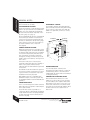
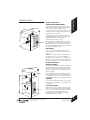
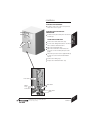
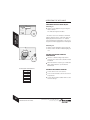
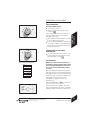
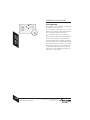
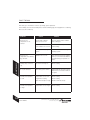
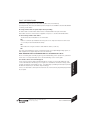
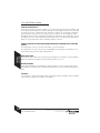
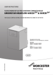
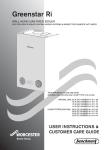
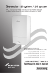
USER INSTRUCTIONS & CUSTOMER CARE GUIDE
FLOOR STANDING RSF GAS-FIRED CONDENSING COMBINATION
BOILER
GREENSTAR
HIGHFLOW 440/550CDi
FOR SEALED CENTRAL HEATING SYSTEMS AND MAINS FED DOMESTIC HOT WATER
THE APPLIANCE IS FOR USE WITH
NATURAL GAS OR L.P.G. (Cat II 2H3P TYPE C13, C33 & C53)
NATURAL GAS:
GREENSTAR HIGHFLOW 440CDi GC NUMBER 47-406-24
GREENSTAR HIGHFLOW 550CDi GC NUMBER 47-406-25
LIQUID PETROLEUM GAS:
GREENSTAR HIGHFLOW 440CDi GC NUMBER 47-406-26
GREENSTAR HIGHFLOW 550CDi GC NUMBER 47-406-27
UK/IE
8 716 115 220b (03.2010)
CONTACT INFORMATION
USER INSTRUCTIONS & CUSTOMER
CARE GUIDE
WORCESTER BOSCH:
PLEASE READ THESE INSTRUCTIONS
TECHNICAL:
0844 892 3366
SERVICE:
0844 892 3000
CAREFULLY BEFORE OPERATING YOUR
BOILER
LITERATURE:
0844 892 9800
SALES:
01905 752640
WEBSITE: www.worcester-bosch.co.uk
THESE INSTRUCTIONS ARE APPLICABLE TO
THE WORCESTER, BOSCH GROUP BOILER
MODEL(S) STATED ON THE FRONT COVER
OF THIS MANUAL ONLY AND MUST NOT BE
USED WITH ANY OTHER MAKE OR MODEL OF
BOILER.
THE INSTRUCTIONS APPLY IN THE UK ONLY
AND SHOULD BE FOLLOWED EXCEPT FOR
ANY STATUTORY OBLIGATION.
IF YOU ARE IN ANY DOUBT CONTACT THE
WORCESTER, BOSCH GROUP TECHNICAL
SUPPORT.
DISTANCE LEARNING AND TRAINING
COURSES ARE AVAILABLE FROM
WORCESTER, BOSCH GROUP.
THIS BOILER MUST BE INSTALLED BY A GAS
SAFE REGISTERED, COMPETENT PERSON.
FAILURE TO INSTALL CORRECTLY COULD
LEAD TO PROSECUTION.
PLEASE LEAVE THIS GUIDE, THE
INSTALLATION INSTRUCTIONS AND THE
COMPLETED BENCHMARK CHECKLIST
WITH THE USER.
NOTE: THE BENCHMARK CHECKLIST AND
SERVICE INTERVAL RECORD CAN BE
FOUND AT THE REAR OF THE
INSTALLATION, COMMISSIONING AND
SERVICE INSTRUCTIONS.
ABBREVIATIONS USED IN THIS BOOK:
NG - Natural Gas
LPG - Liquid Petroleum Gas
CH - Central Heating
SEDBUK - Seasonal Efficiency of Domestic
Boilers in the United Kingdom
USER INSTRUCTIONS & CUSTOMER CARE GUIDE
8 716 115 220b (03.2010)
2
3
4
USING YOUR APPLIANCE
CONTROLS
Access to the controls
Access to the filling loop connection
OPERATING THE APPLIANCE
Switching the appliance on/off
Setting the central heating temperature
Controlling central heating
Frost protection
Controlling the hot water temperature
ECO indicator
Fault condition
8
8
8
9
9
9
10
MAINTENANCE
MAINTAINING YOUR BOILER
FAULT FINDING
FAULT OR BREAKDOWN
11
12
13
ENERGY SAVING
TIPS ON ENERGY SAVING
14
GUARANTEE
YOUR GUARANTEE
GUARANTEE REGISTRATION
16
17
ENERGY
SAVING
USING YOUR
APPLIANCE
6
7
7
MAINTENANCE
INTRODUCTION
SAFETY PRECAUTIONS
GENERAL INFORMATION
GENERAL NOTES
INTRODUCTION
CONTENTS
Thank you for purchasing a Greenstar gas-fired condensing combination boiler manufactured
by Worcester, Bosch Group. The company prides itself on manufacturing boilers to the
strictest quality control standards throughout every stage of production.
Worcester, Bosch Group has led the field in innovative boiler design and performance for
more than 40 years. This heritage means all products are of exceptional quality and proven
reliability.
The Greenstar range in particular is extremely energy efficient, offering you economical
running costs and value for money. It sits in SEDBUK Band A, and is therefore amongst
the top energy rated boilers available.
GUARANTEE
Dedicated to heating comfort
There is also the reassurance of our no-nonsense 2 years parts and labour guarantee backed up by Worcester Total Cover, an optional complete maintenance scheme to keep
your boiler operating at peak condition and efficiency.
To find out more about Worcester, Bosch Group log onto www.worcester-bosch.co.uk .
USER INSTRUCTIONS & CUSTOMER CARE GUIDE
8 716 115 220b (03.2010)
CONTENTS
1
INTRODUCTION
SAFETY PRECAUTIONS
IF YOU SMELL GAS:
DO NOT SMOKE OR STRIKE MATCHES.
DO NOT TURN ELECTRICAL SWITCHES ON OR OFF.
PUT OUT NAKED FLAMES.
OPEN DOORS AND WINDOWS.
KEEP PEOPLE AWAY FROM THE AREA AFFECTED.
TURN OFF THE CONTROL VALVE AT THE METER.
CALL YOUR GAS COMPANY
-ORCALL 0800 111 999 NATIONAL GRID EMERGENCY SERVICES.
BOILER OPERATION:
This boiler must only be operated by a responsible adult who has been instructed in,
understands and is aware of the boiler’s operating conditions and effects.
COMBUSTIBLE AND CORROSIVE MATERIALS:
Do not store or use any combustible materials (paper, thinners, paints etc.) inside or within
the vicinity of the boiler.
Chemically aggressive substances can corrode the boiler and invalidate any warranty.
FITTING & MODIFICATIONS
Fitting the boiler, any controls to the boiler and removal of the outer casing may only be
carried out by a competent engineer in accordance with the Gas Safety (Installation and Use)
Regulations.
Flue systems must not be modified in any way other than as described in the Installation
instructions and any misuse or unauthorised modifications to the boiler, flue or associated
components and systems could invalidate the warranty. The manufacturer accepts no liability
arising from any such actions. This does not affect your statutory rights.
2
SAFETY PRECAUTIONS
USER INSTRUCTIONS & CUSTOMER CARE GUIDE
8 716 115 220b (03.2010)
SERVICING
The boiler must be serviced regularly by a competent, qualified person, such as a Worcester
service engineer or alternatively a British Gas or other GAS SAFE registered person.
Always use original spares, to help maintain the economy, safety and reliability of the boiler
and have the Service Record completed in the Benchmark checklist.
INTRODUCTION
GENERAL INFORMATION
The Benchmark Scheme
Worcester, Bosch Group is a licensed member of the Benchmark Scheme which aims to
improve the standards of installation and commissioning of domestic heating and hot water
systems in the UK and to encourage regular servicing to optimise safety, efficiency and
performance.
Please ensure that the installer has fully completed the Benchmark Checklist on the inside
back pages of the installation instructions supplied with the product and that you have
signed it to say that you have received a full and clear explanation of its operation. The
installer is legally required to complete a commissioning checklist as a means of complying
with the appropriate Building Regulations (England and Wales).
All installations must be notified to Local Area Building Control either directly or through
a Competent Persons Scheme. A Building Regulations Compliance Certificate will then be
issued to the customer who should, on receipt, write the Notification Number on the
Benchmark Checklist.
This product should be serviced regularly to optimise its safety, efficiency and performance.
The service engineer should complete the relevant Service Record on the Benchmark
Checklist after each service.
The Benchmark Checklist may be required in the event of any warranty work and as
supporting documentation relating to home improvements in the optional documents
section of the Home Information Pack.
NOTE: The Benchmark checklist and service interval record can be found at the rear of
the Installation, Commissioning and Servicing Instructions.
HEALTH & SAFETY
The boiler contains no asbestos and no substances used in the construction process that
contravene the COSHH Regulations (Control of Substances Hazardous to Health Regulations
1988).
USER INSTRUCTIONS & CUSTOMER CARE GUIDE
8 716 115 220b (03.2010)
GENERAL INFORMATION
3
INTRODUCTION
GENERAL NOTES
To get the best from your boiler please read
these instructions carefully.
SEALED HEATING SYSTEMS
This boiler is fitted to a sealed heating system
which is pre-pressurised. Your installer will
advise you of the minimum and maximum
pressure which should be indicated on the
pressure gauge (see page 7).
CLEARANCES - SERVICE
Your installer will have provided adequate
space around the boiler for safety and servicing
access. Do not restrict this space with the
addition of cupboards, shelves etc. next to
the boiler.
Check regularly that the pressure is maintained
and contact your installer or maintenance
engineer if a permanent significant drop in
pressure is indicated on the pressure gauge.
If the system loses pressure it should be repressurised and the cause of the fall
investigated.
During the first few hours of operation of the
central heating system, check that all radiators
are being heated evenly. If the top of a radiator
is at a lower temperature than the bottom
then it should be vented by releasing air
through the venting screw at the top of the
radiator. Ask your installer to show you how
this is done.
This boiler is fitted to a sealed system;
repeated venting will reduce the quantity of
water in the system and this must be
replenished for safe and satisfactory operation
of the boiler.
Should water leaks be found in the system or
if excessive venting is required, then a service
engineer must be contacted to inspect the
installation and rectify any fault.
Only additives that are compatible with
aluminium may be used in the system. Any
incompatible additive used will invalidate the
guarantee.
CONDENSATE DRAIN
This is a condensing boiler and the terminal
will, at times give out a plume of water vapour.
This is quite normal.
The boiler also produces quantities of
condensate which is discharged regularly by
a trap within the boiler via a pump and pipe
to drain. This pipe must not be blocked or
altered in any way.
4
GENERAL NOTES
610mm
15mm
865mm
CENTRAL HEATING SYSTEMS
1200mm
5mm
600mm
5mm
ROOM THERMOSTAT
A room temperature controller and
programmer should be fitted to control the
central heating. Refer to the instructions
supplied with the thermostat for information
on siting and setting.
THERMOSTATIC RADIATOR VALVES
TRVs should fitted to all but one of the
radiators (or at least those in the sleeping
accommodation). The radiator without the
TRV must be in the same room as the room
thermostat, and must be uncontrolled and
unrestricted. The thermostatic radiator valves
should conform to the requirements of
BS2767:10.
USER INSTRUCTIONS & CUSTOMER CARE GUIDE
8 716 115 220b (03.2010)
800mm
800mm
900mm
50mm
100mm**
100mm**
200mm*
625mm
800mm
100mm
1050mm
25mm
200mm
100mm
25mm
100mm
BOILER CLEARANCES UNVENTILATED COMPARTMENT
The diagram opposite shows the minimum
space required to install and service the boiler
inside an unventilated compartment.
* Space required for unventilated areas with
a removable door or panel, but 600mm to a
fixed surface for servicing.
** This space can be reduced to 50mm for
one side only as long as both side clearances
add up to the total of both the side
measurements shown, or more.
Two examples are shown opposite, refer to
the ‘Installation, commissioning and servicing
instruction manual’ for further information.
Do not add cupboards, shelves etc. to restrict
the space around the boiler.
VENTILATION
This is a room sealed boiler and does not
require any air for combustion from inside the
property.
In spite of the requirements of BS 6798 and
BS 5440 there is no need for ventilation
openings to be provided in the compartment
because of the low heat loss from the boiler
casing, if the clearances shown are maintained.
BOILER CLEARANCES AIRING CUPBOARD
If the boiler is fitted into an airing cupboard
then the diagram opposite shows the minimum
clearances required around the boiler and
also the clearances for any shelf constructed
above the boiler.
If a compartment is built around the boiler
after installation, then the compartment must
be separated from the boiler space by a noncombustible partition as described in BS 6798.
WARNING
Do not operate the boiler if the flue terminal
fitted on the outside wall or roof is obstructed
or damaged.
PUMP ANTI-SEIZURE
If there has been no heating demand for 24
hours, the boiler will run the system pump for
a few seconds. This is to reduce the possibility
of pump seizure during long periods of
inactivity which are usually more frequent
during the summer months.
USER INSTRUCTIONS & CUSTOMER CARE GUIDE
8 716 115 220b (03.2010)
GENERAL NOTES
INTRODUCTION
GENERAL NOTES
5
CONTROLS
J
USING YOUR
APPLIANCE
K
A
I
D
E
F
H
L
M
C
G
B
A - MASTER SWITCH FOR ON/OFF
B - MAINS ON/OFF INDICATOR + FAULT DIAGNOSTIC LIGHT
C - CENTRAL HEATING TEMPERATURE CONTROL
D - BURNER ON INDICATOR LIGHT (GREEN)
E - FAULT RESET BUTTON
F - SERVICE BUTTON
G - DOMESTIC HOT WATER TEMPERATURE CONTROL
H - ECO BUTTON
I - SYSTEM PRESSURE GAUGE
J - POSITION FOR OPTIONAL PROGRAMMER
K - DISPLAY
L - CENTRAL HEATING BOOST BUTTON
M - NOT USED
6
CONTROLS
USER INSTRUCTIONS & CUSTOMER CARE GUIDE
8 716 115 220b (03.2010)
CONTROLS
TO ACCESS THE CONTROLS
Pull the centre top of the cover panel to
allow the cover to open.
Pull the front panel away from the boiler
and lift up.
USING THE FILLING LOOP
2
Connect the filling link between the Flow
valve and the Tank drain valve.
1
PULL
Remove the Tank drain valve cap.
LIFT
USING YOUR
APPLIANCE
TO ACCESS THE FILLING LOOP
CONNECTION
CONTROLS
COVER
Open the Tank drain valve.
Open the Flow valve and monitor the
pressure on the Control panel pressure
gauge.
When the pressure reaches approximately
1.5 bar close the Flow and Tank drain
valves.
Remove the filling loop.
Repace the Tank drain valve cap.
Flow valve
Tank drain
Filling
Loop
connection
Tank drain
valve
USER INSTRUCTIONS & CUSTOMER CARE GUIDE
8 716 115 220b (03.2010)
CONTROLS
7
OPERATING THE APPLIANCE
SWITCHING THE APPLIANCE ON/OFF
Switching on
Switch on the appliance by pressing the
master switch.
The indicator light shows blue
USING YOUR
APPLIANCE
• The boiler runs for 15 minutes at minimum
heating output to fill the condensate trap, the
display (K) alternates between ‘-II-’ and the
central heating flow temperature. This occurs
every time the mains supply has been interrupted.
Switching off
Switch off the appliance by pressing the
master switch. The blue indicator light goes
out.
SETTING THE CENTRAL HEATING
TEMPERATURE
Turn the central heating temperature
control to the desired level, between 35°C
and 88°C.
When the burner is lit, the green indicator
light underneath the on/off switch is
illuminated.
APPROXIMATE TEMPERATURES
--- OFF
1
--- 35 ºC
Set the timer to the correct time.
2
--- 40 ºC
3
--- 50 ºC
Set room thermostat to the desired room
temperature.
4
--- 65 ºC
5
--- 75 ºC
6
--- 85 ºC
Max --- 88 ºC
8
CONTROLLING CENTRAL HEATING
*
OPERATING THE APPLIANCE
Set the thermostatic radiator valves to the
desired settings.
USER INSTRUCTIONS & CUSTOMER CARE GUIDE
8 716 115 220b (03.2010)
OPERATING THE APPLIANCE
FROST PROTECTION
If heating is NOT required:
Leave master switch on.
If the temperature falls to 5 °C inside the
boiler, the boiler will fire to prevent the
possibility of freezing.
Add a suitable anti-freeze fluid to the water
in the central heating system.
If remote pipework is likely to be subjected
to freezing conditions, ensure the installer
has fitted a frost thermostat in the area to
protect the pipework.
USING YOUR
APPLIANCE
Turn the central heating temperature
control to
CONTROLLING THE HOT WATER
TEMPERATURE
The hot water temperature can be set to
between approx. 45 °C and 65 °C using
the temperature control
ECO INDICATOR
APPROXIMATE TEMPERATURES
Min. --- 45 ºC
1
--- 50 ºC
2
--- 52 ºC
3
--- 54 ºC
4
--- 56 ºC
5
--- 58 ºC
6
--- 60 ºC
Max. --- 65 ºC
NOTE: If your boiler has an in-built fascia
mounted programmer and the mains supply
is interupted, the ECO button will need to
be reset by pressing and holding for three
seconds.
When the ECO button IS lit the pre-heated
tank of hot water is turned off, but the boiler
will supply hot water as a normal Combi boiler.
It will take longer to obtain hot water at the
tap in ECO mode as the boiler is not
maintaining a supply of hot water for
immediate use.
When the ECO button is NOT lit the boiler is
in pre-heat mode for hot water.
Hot water will now be available at the tap
almost immediately as the boiler constantly
maintains a tank of hot water ready for use.
USER INSTRUCTIONS & CUSTOMER CARE GUIDE
8 716 115 220b (03.2010)
OPERATING THE APPLIANCE
9
OPERATING THE APPLIANCE
FAULT CONDITION
In the unlikely event of a fault occurring while
the appliance is in operation:
The reset button will flash once per second
and the mains indicator (blue light) will flash
also. The display shows a fault code.
USING YOUR
APPLIANCE
To reset boiler press the reset button.
10
The reset button will no longer be illuminated
and the mains indicator will stop flashing.
The boiler will function normally, dependent
on programmer and room thermostat settings.
If the fault remains and cannot be cleared by
pressing the reset button, or if fault persists
contact British Gas for assistance, giving a
description of the fault and, if possible, the
fault code from the display.
OPERATING THE APPLIANCE
USER INSTRUCTIONS & CUSTOMER CARE GUIDE
8 716 115 220b (03.2010)
MAINTAINING YOUR BOILER
Your new Greenstar gas-fired boiler represents a long term investment in a reliable, high
quality product.
In order to realise its maximum working life, and to ensure it continues to operate at peak
efficiency and performance, it is essential that your boiler receives regular servicing and
maintenance checks from a competent person beyond the initial 2 year guarantee period.
If you would like to know more about a Worcester, Bosch Group service contract, please tick
the appropriate box on your warranty registration card.
If your Greenstar gas-fired boiler should fail to operate correctly or requires servicing please
contact the Worcester, Bosch Group Service Department (see inside front cover for details).
MAINTENANCE
Details of the boiler including the Gas Council number can be found under the controls cover
flap on the boiler.
USER INSTRUCTIONS & CUSTOMER CARE GUIDE
8 716 115 220b (03.2010)
MAINTAINING YOUR BOILER
11
FAULT FINDING
This table gives information on basic operating system problems.
In the unlikely event of a boiler fault please read the following page thoroughly before contacting
Worcester, Bosch Group.
PROBLEM
MAINTENANCE
REMEDY
Thermostatic radiator
valve(s) set too low
Increase thermostatic radiator
valve setting(s)
Temperature control for CH
flow on boiler set too low
Increase CH flow temperature
control setting
Air trapped in heating
system
Bleed radiators and recharge
heating system
Desired room
temperature exceeded by
large amount
Radiators are too hot
Turn down thermostatic radiator
valves / room thermostat Reduce
central heating temperature on
boiler
Heating stays on for too
long
Clock is incorrectly set
Check setting
No on/off indicator
Momentary power failure
Switch off boiler at master switch,
wait a few seconds then switch
on again
Hot water temperature
too low
Temperature set too low
Check setting
Programmer setting
Check setting
Water flow at tap too high
Reduce flow rate at tap
Temperature set too high
Check setting
Desired room
temperature is not
reached
Hot water temperature
too high
12
CAUSE
FAULT FINDING
USER INSTRUCTIONS & CUSTOMER CARE GUIDE
8 716 115 220b (03.2010)
FAULT OR BREAKDOWN
This boiler is supported in the UK and Eire by Worcester, Bosch Group.
Specially trained, Worcester, Bosch Group Service Engineers are available to attend a breakdown
occurring on this boiler.
No charge will be made for parts and/or labour providing:
An boiler fault is found and the boiler has been installed within the past 24 months.
Reasonable evidence of this must be supplied on request. i.e. the Benchmark Checklist.
A call-out charge will be made where:
The boiler has been installed for over 24 months.
OR
Evidence cannot be provided that the first year service inspection has been carried out
(i.e. an entry in the Benchmark Checklist).
OR
Our Field Service Engineer finds no fault with the boiler (see Note).
OR
The cause of breakdown is misuse or with other parts of your plumbing/heating system, or
with equipment not supplied by Worcester, Bosch Group.
NOTE: NO BOILER FAULT IS FOUND ON OVER 30% OF SERVICE CALL OUTS.
Please read this guide carefully to gain a good understanding of the operation of your boiler.
In the case of a suspected fault, refer to the fault finding section of this guide.
In the event of an boiler fault or breakdown please contact our Service Department. Your
service administrator will arrange for an engineer to call with the minimum of delay; under
normal circumstances this will be from 1 - 3 working days (excluding weekends) for priority
breakdown situations (no hot water and/or heating).
Invoices for attendance and repair work carried out on this boiler by any third party will not
be accepted.
USER INSTRUCTIONS & CUSTOMER CARE GUIDE
8 716 115 220b (03.2010)
FAULT OR BREAKDOWN
MAINTENANCE
If in doubt contact our Technical Support
13
TIPS ON ENERGY SAVING
HEATING ECONOMICALLY
The boiler is designed to provide a high level of comfort while keeping gas consumption and
the resulting environmental effect as low as possible. The gas supply to the burner is controlled
according to the level of demand for heat. The boiler continues to operate with a low flame
if the demand for heat reduces. The technical term for this process is modulating control.
Modulating control reduces temperature fluctuations and provides even distribution of heat
throughout the home. This means that the boiler may stay on for relatively long periods but
will use less gas than a boiler that continually switches on and off.
CENTRAL HEATING SYSTEMS WITH ROOM THERMOSTATS/THERMOSTATIC RADIATOR
VALVES
The temperature control on the boiler should be set to the maximum.
The temperature of each room can be set individually (except primary room with the room
thermostat) using the thermostatic radiator valves.
ENERGY
SAVING
ROOF INSULATION
Around 30% of the heat loss from a property is through the roof. Replace any old insulation
with new insulation, preferably of around 200mm thickness or more.
WINDOW FRAMES
Single glazed windows, particularly those with steel frames, can lose a great deal of heat.
Consideration should be given to replacement with PVCu or wooden framed double glazed
units.
CURTAINS
Lined curtains, or heavier full length curtains can provide excellent insulation. However, always
ensure that the curtains do not drape over radiators.
14
TIPS ON ENERGY SAVING
USER INSTRUCTIONS & CUSTOMER CARE GUIDE
8 716 115 220b (03.2010)
TIPS ON ENERGY SAVING
DRAUGHTS
Try to ensure that draughts around doors, windows, letterboxes and keyholes etc. are reduced
by using a suitable draught excluder. Warning - Do not block or seal any air vents that are
installed to ensure the central heating boiler operates safely.
ROOM THERMOSTATS
Reducing the setting of the room thermostat by 1°C can reduce fuel consumption by up to
10%.
NEW CONTROL SYSTEMS
Upgrade your heating control system if necessary with the latest equipment available. The
minimum level of control is a programmer, interlocking room thermostat and thermostatic
radiator valves.
More often than not radiators will be sited underneath a window, so the warm air from the
radiator heats the colder incoming air from the window. The performance of the radiator will
be affected if the curtains are allowed to drape over the radiator or shelves are fitted above
it. The positioning of furniture and tables in front of the radiator should also be avoided.
It is advisable to manually adjust all radiator thermostatic valves every 2-3 months to prevent
them sticking. It is also important that the plastic tops of all valves are always in position and
not cracked or damaged to prevent accidents. Care should be taken when vacuum cleaning
carpets to avoid damage to valves and pipework.
ENERGY
SAVING
RADIATORS
The heating system and the outputs of the radiators have been carefully selected by your
installer. The temperature obtainable in any given room is dependent on all radiators being
operated at the same time. If you decide to turn off radiators in unused rooms, spare bedrooms
etc., you may experience slightly lower room temperatures in rooms adjacent to unheated
rooms.
USER INSTRUCTIONS & CUSTOMER CARE GUIDE
8 716 115 220b (03.2010)
TIPS ON ENERGY SAVING
15
YOUR GUARANTEE
This boiler is guaranteed against faulty material or workmanship for a period of 2 years
from the date of installation subject to the following terms and conditions:
Your Guarantee Registration Card must be returned within 30 days for the second year of
your guarantee to become valid.
During the period of this guarantee any components of the unit which are proven to be
faulty or defective in manufacture will be exchanged or repaired free of charge by Bosch
Thermotechnology Ltd.
The householder may be asked to prove the date of installation, that the boiler was correctly
commissioned and, where appropriate, the first year’s service inspection has been carried
out to the satisfaction of Bosch Thermotechnology Ltd., when requested. These should be
part of the Benchmark Checklist.
Any product or part returned for servicing under the guarantee must be accompanied by
a claim stating the model, serial number & date of installation.
Bosch Thermotechnology Ltd., will not accept responsibility for damage caused by faulty
installation, neglect, misuse or accidental damage or the non-observance of the instructions
contained in the Installation Commissioning and Servicing Instructions and User Instructions
and Customer Care Guide.
The boiler has been used only for the normal domestic purposes for which it was designed.
This guarantee does not affect your statutory rights.Your Guarantee Registration Card must
be returned within 30 days for the second year of your guarantee to become valid.
This guarantee applies only to equipment purchased and used in the United Kingdom and
Eire.
GUARANTEE
This guarantee does not affect your statutory rights.
16
YOUR GUARANTEE
USER INSTRUCTIONS & CUSTOMER CARE GUIDE
8 716 115 220b (03.2010)
GUARANTEE REGISTRATION
You should complete and return the postpaid
Guarantee Registration Card within 30 days
of purchase.
Returning the card will register you as the
owner of your new Greenstar boiler and will
assist us in maintaining an effective and
efficient customer service by establishing a
reference and permanent record for your
boiler.
This does not affect your statutory rights.
For your own record:
MODEL:
SERIAL No.
(See identity label inside the appliance casing)
TYPE / SIZE:
DATE OF INSTALLATION:
GUARANTEE
NAME OF INSTALLER:
TELEPHONE NUMBER OF INSTALLER:
Please ensure that the Benchmark Checklist has been completed
by your installer or service engineer.
USER INSTRUCTIONS & CUSTOMER CARE GUIDE
8 716 115 220b (03.2010)
GUARANTEE REGISTRATION
17
Worcester, Bosch Group
Cotswold Way, Warndon, Worcester WR4 9SW
Tel. 0844 892 9900 Fax. 01905 754619
Worcester, Bosch Group is a brand name of
Bosch Thermotechnology Ltd.
worcester-bosch.co.uk
8 716 115 220b (03.2010)