1
Betriebsanleitung • Operating Instructions
Translation of the Original Operating Instructions
Compact Turbo™
TurboDrag Pump
PM 0470 BE/O (0709)
TMH 261
TMU 261
idealvac.com
(505)872-0037
idealvac.com
Table of contents
Table of contents
1
1.1
1.2
2
2.1
2.2
2.3
3
3.1
3.2
4
4.1
4.2
4.3
5
5.1
5.2
5.3
5.4
5.5
5.6
5.7
6
6.1
6.2
6.3
6.4
6.5
7
7.1
7.2
7.3
8
8.1
8.2
8.3
9
9.1
10
11
12
13
13.1
2
About this manual . . . . . . . . . . . . . . . . . . . . . . . . . . . . . . . . . . . . . . 3
Validity. . . . . . . . . . . . . . . . . . . . . . . . . . . . . . . . . . . . . . . . . . . . . . . . 3
Conventions . . . . . . . . . . . . . . . . . . . . . . . . . . . . . . . . . . . . . . . . . . . 3
Safety . . . . . . . . . . . . . . . . . . . . . . . . . . . . . . . . . . . . . . . . . . . . . . . . 5
Safety precautions . . . . . . . . . . . . . . . . . . . . . . . . . . . . . . . . . . . . . . 5
Proper use. . . . . . . . . . . . . . . . . . . . . . . . . . . . . . . . . . . . . . . . . . . . . 5
Improper use . . . . . . . . . . . . . . . . . . . . . . . . . . . . . . . . . . . . . . . . . . . 6
Transport and storage . . . . . . . . . . . . . . . . . . . . . . . . . . . . . . . . . . 6
Transport . . . . . . . . . . . . . . . . . . . . . . . . . . . . . . . . . . . . . . . . . . . . . . 6
Storage . . . . . . . . . . . . . . . . . . . . . . . . . . . . . . . . . . . . . . . . . . . . . . . 6
Product description . . . . . . . . . . . . . . . . . . . . . . . . . . . . . . . . . . . . 7
Product identification . . . . . . . . . . . . . . . . . . . . . . . . . . . . . . . . . . . . . 7
Function . . . . . . . . . . . . . . . . . . . . . . . . . . . . . . . . . . . . . . . . . . . . . . 7
Range of application . . . . . . . . . . . . . . . . . . . . . . . . . . . . . . . . . . . . . 8
Installation . . . . . . . . . . . . . . . . . . . . . . . . . . . . . . . . . . . . . . . . . . . . 9
Set-up . . . . . . . . . . . . . . . . . . . . . . . . . . . . . . . . . . . . . . . . . . . . . . . . 9
Preparatory work . . . . . . . . . . . . . . . . . . . . . . . . . . . . . . . . . . . . . . . . 9
Assembly. . . . . . . . . . . . . . . . . . . . . . . . . . . . . . . . . . . . . . . . . . . . . . 9
Connections to the turbopump . . . . . . . . . . . . . . . . . . . . . . . . . . . . 13
Connecting Pfeiffer Vacuum display and control units or PC . . . . . 16
Connecting the remote control . . . . . . . . . . . . . . . . . . . . . . . . . . . . 17
Connections diagram TC. . . . . . . . . . . . . . . . . . . . . . . . . . . . . . . . . 19
Operation . . . . . . . . . . . . . . . . . . . . . . . . . . . . . . . . . . . . . . . . . . . . 20
Operation modes. . . . . . . . . . . . . . . . . . . . . . . . . . . . . . . . . . . . . . . 20
Commissioning . . . . . . . . . . . . . . . . . . . . . . . . . . . . . . . . . . . . . . . . 20
Function description . . . . . . . . . . . . . . . . . . . . . . . . . . . . . . . . . . . . 21
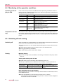
Monitoring of the operation conditions . . . . . . . . . . . . . . . . . . . . . . 24
Switching off and venting . . . . . . . . . . . . . . . . . . . . . . . . . . . . . . . . 24
Maintenance / replacement . . . . . . . . . . . . . . . . . . . . . . . . . . . . . 25
Maintenance intervals and responsibilities . . . . . . . . . . . . . . . . . . . 25
Replacing the operating fluid reservoir . . . . . . . . . . . . . . . . . . . . . . 25
Replacing the electronic drive unit . . . . . . . . . . . . . . . . . . . . . . . . . 28
Decommissioning . . . . . . . . . . . . . . . . . . . . . . . . . . . . . . . . . . . . . 29
Shutting down for longer periods. . . . . . . . . . . . . . . . . . . . . . . . . . . 29
Re-starting. . . . . . . . . . . . . . . . . . . . . . . . . . . . . . . . . . . . . . . . . . . . 29
Disposal . . . . . . . . . . . . . . . . . . . . . . . . . . . . . . . . . . . . . . . . . . . . . 29
Malfunctions . . . . . . . . . . . . . . . . . . . . . . . . . . . . . . . . . . . . . . . . . 30
Rectifying malfunctions . . . . . . . . . . . . . . . . . . . . . . . . . . . . . . . . . . 30
Service . . . . . . . . . . . . . . . . . . . . . . . . . . . . . . . . . . . . . . . . . . . . . . 31
Spare parts TMH/U 261 . . . . . . . . . . . . . . . . . . . . . . . . . . . . . . . . . 32
Accessories . . . . . . . . . . . . . . . . . . . . . . . . . . . . . . . . . . . . . . . . . . 33
Technical data . . . . . . . . . . . . . . . . . . . . . . . . . . . . . . . . . . . . . . . . 34
Dimension diagrams . . . . . . . . . . . . . . . . . . . . . . . . . . . . . . . . . . . . 35
Manufacturer‘s Declaration . . . . . . . . . . . . . . . . . . . . . . . . . . . . . 36
About this manual
1
About this manual
1.1 Validity
This operating manual is for customers of Pfeiffer Vacuum. It describes the functioning of the designated product and provides the most important information for
safe use of the unit. The description follows applicable EU guidelines. All information provided in this operating manual refer to the current state of the product's development. The documentation remains valid as long as the customer does not
make any changes to the product.
Up-to-date operating instructions can also be downloaded from
www.pfeiffer-vacuum.net.
Applicable documents
TMH/U 261
Operating instructions
Safety information for vacuum pumps "Safety Guide"
PT 0300 BN*
Operating instructions "Pumping operations with DCU"
PM 0547 BN*
Operating instructions "Pfeiffer Vacuum protocol"
PM 0488 BN*
Manufacturer’s declaration
Part of this document
Operating instructions for accessories
see section "accessories"*
*also available via www.pfeiffer-vacuum.net
For information about other certifications, if applicable, please see the signet on
the pump or:
• www.tuvdotcom.com
• TUVdotCOM-ID 0000021320
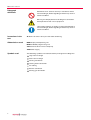
1.2 Conventions
Safety instructions
The safety instructions in Pfeiffer Vacuum operating manuals are the result of risk
evaluations and hazard analyses and are oriented on international certification
standards as specified by UL, CSA, ANSI Z-535, Semi-S1, ISO 3864 and DIN 4844.
In this document, the following hazard levels and information are considered:
DANGER
Immediate danger
Death or very severe injuries occur.
WARNING
Possible danger
Death or injuries may occur.
CAUTION
Possible danger
Medium to slight injuries may occur.
NOTE
Command or note
Command to perform an action or information about properties, the disregarding of
which may result in damage to the product.
3
About this manual
Piktograph
definitions
Prohibition of an action or activity in connection with a
source of danger, the disregarding of which may result in
serious accidents.
Warning of a displayed source of danger in connection
with operation of the unit or equipment.
Command to perform an action or task associated with a
source of danger, the disregarding of which may result in
serious accidents.
Instructions in the
text
Î Work instruction: here you have to do something.
Abbreviations used
DCU:Display and operating unit
HPU:Handheld programming unit
TC:Electronic drive unit for turbopump
TPS:Power supply
Symbols used
The following symbels are used consistently throughout the diagrams:
H High vacuum flange
VV
Fore-vacuum flange
F
Venting connection
Cooling water connection
Air cooling
Electric connection
G Sealing gas connection
4
Safety
2
Safety
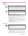
2.1 Safety precautions
NOTE
Duty to inform
Each person involved in the installation, operation or maintenance of the vacuum
pump must read and observe the safety-related parts of these operating instructions.
Î Absolute observe the safety information for vacuum pumps (PT 0300 BN) !
Î The operator is obligated to make operating personnel aware of dangers originating
from the vacuum pump, the pumped medium and the entire system.
NOTE
Installation and operation of accessories
Pfeiffer Vacuum pumps can be equipped with a series of adapted accessories. The
installation, operation and maintenance of connected devices are described in detail in
the operating instructions of the individual components.
Î For information on the operating instructions of components, see "Accessories".
Î Use original accessory parts only.
• Do not loosen any plug connection during operations.
• Wait for the rotor to reach standstill before peforming work on the high vacuum
flange.
• When using sealing gas, the pressure in the hose connection must be limited to
2 bar via an overpressure valve.
• Keep leads and cables well away from hot surfaces (> 70 °C).
• Always ensure a safe connection to the protective earthing conductor (PE, protection class I).
• Discrete operating of the turbopump and the electronic drive unit is only allowed after authorisation by Pfeiffer Vacuum. In this case the turbopump must be
connected to the PE.
• The danger of an electrical shock in the case of ground leakage must be eliminated immediately (red LED flashes).
• Never fill or operate turbopump with cleaning agent.
2.2 Proper use
NOTE
CE conformity
The manufacturer's declaration becomes invalid if the operator modifies the original
product or installs additional components!
Î Following installation into a plant and before commissioning, the operator must
check the entire system for compliance with the valid EU directives and reassess it
accordingly.
• Only operate the turbopump with a prooved backing pump.
• Only operate the turbopump with TC by a specified Pfeiffer Vacuum power supply. The use of other power units than the intended, is only permitted after consultation with Pfeiffer Vacuum.
• Only operate the turbopump with TC 600 in ambient conditions up to protection
class IP 30.
• Only operate the turbopump together with a water cooling unit or in ambient
conditions up to protection class IP 54 after installing a specified TC cover plate.
5
Transport and storage
2.3 Improper use
Improper use will cause all claims for liability and guarantees to be forfeited. Improper use is deemed to be all use for purposes deviating from those mentioned
above, especially:
•
•
•
•
•
•
•
•
•
Pumping of corrosive or explosive media.
Pumping of condensing vapors.
Operation with improper high levels of gas loads.
Operation with improper high fore-vacuum pressures.
Operation with improper gas mode.
Operation with improper high levels of insulated heat input.
Venting with improper high venting rates.
Operation of the pump in potentially radioactive areas.
Installation in systems where the turbopumps are subjected to impact-like stress
and vibrations or the effect of periodically occurring forces.
• The connection to a power supply with earthing of a direct voltage pole.
• The use of accessories, which are not named in this manual or not authorised
by Pfeiffer Vacuum.
3
Transport and storage
3.1 Transport
Î Reuse the transport container. Vacuum pumps should be transported or shipped
in the original packing only.
Î Only remove the protective covers from the high vacuum and the fore-vacuum
side immediately before connection.
Î Preserve the original protective covers.
Î Always transport the turbopump uprightly.
3.2 Storage
Î Close the flange openings by using the original protective covers.
Î Close further connection ports by using the corresponding protective covers.
Î Storage the pump only indoors with an ambient temperature between -25 °C
and +55 °C.
Î In rooms with moist or aggressive atmospheres, the turbopump must be air-seeled in a plastic bag together with a bag of dessicant.
6
Product description
4
Product description
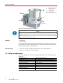
4.1 Product identification
Pump types
The product designations of Pfeiffer vacuum turbomolecular pumps are self-explanatory and permit conclusions about the different versions. The product designation consists of a family designation (1), the size (2), which is oriented on the
pumping speed, and the properties (3) of the pump.
TMH(1) 261(2) P(3)
1. Family designation
2. Model designation
T = Turbopump
P = Pure turbopump
M = Turbo with Holweck stage
261 = Model designaH = ISO-flange variants for high tion of the pump related
vacuum applications
to its pumping speed
U = CF-flange variants for ultraclass
high vacuum applications
D = "Drag" pump for the medium
vacuum range
3. Properties
U = Upside down version
P = Purge sealing gas system
M = Magnetic bearing
C = for corrosive gases
H = High throughput
T = Temerature management
Y = Installation in any orientation
N = Integrated power supply
To correctly identify the product when communicating with Pfeiffer Vacuum, always have the information from the rating plate available.
D-35614 Asslar
PM 063 265 -T
210 l/s
Mass: 6 kg
TMH 261 P
DN 100 ISO-K, 3P
Mod.-No.: PM P02 821 H
Oil:
Ser. No.:
Made in
Mod.:
S(N2):
Germany 2006/03
Fig. 1: Example for a rating plate
Standard version
Turbopumps without a property, which concernes to the installation orientation
will be characterized as standard version in the following (e.g. TMH 261 P).
Pump features
Scope of delivery
Characteristics
TMH 261
TMU 261
HV flange
DN 100 ISO-K
DN 100 CF-F
• Turbopump
• Protective cover for the high vacuum and the fore-vacuum flange
• Operating instructions
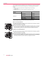
4.2 Function
The turbopumps TMH/U 261 form a complete unit together with the electronic
drive unit TC 600. For the voltage supply only Pfeiffer Vacuum power supplies may
be used (e.g.TPS oder DCU). The use of other power units than the proper intended
is only permitted after consultation with Pfeiffer Vacuum (specification of the power supplies on request).
7
Product description
4
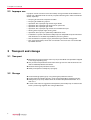
H
8
4
8
High vacuum flange
Electronic drive
unit TC 600
17
Venting screw
20a Fore-vacuum flange
98
Remote plug
17
F
98
VV
20a
Fig. 2: View of CompactTurbo™ TMH 261
NOTE
Observe the connection instructions!
On delivery turbopumps with TC 600 are set up for operations with "Remote Control".
Î Before operating with DCU, HPU or PC the 15-pole D-Sub connector (remote plug)
must be removed from the TC 600.
Cooling
• Air cooling
• Water cooling
In the case of excess temperature the electronic drive unit reduces the rotor rotation speed automatically. Depending on the application and the CompactTurbo™
different cooling variants are selectable.
Rotor bearings
• High vacuum side: maintenance-free permanent magnetic bearing.
• Fore-vacuum side: ceramic ball bearing.
4.3 Range of application
The pumps TMH/U 261 must be installed and operated in the following ambient
conditions.
Installation location
8
weather protected (indoors)
Temperature
+5 °C to +40 °C (up to +35 °C with air cooling)
Protection class
IP 30
Relative humidity
max. 80 %, at T ≤ 31 °C, up to max. 50% at T ≤ 40 °C
Atmospheric pressure:
77 kPa - 106 kPa
Installation altitude
2000 m max.
Degree of pollution
2
Permissible surrounding magnetic field
≤ 6 mT
Overvoltage category
II
Connection voltage TC
48 VDC ±5%
Installation
5
Installation
WARNING
Danger from the turbopump being ripped off.
If the rotor is suddenly blocked, torques of up to 1860 Nm can occur; if the turbopump
is not properly fastened, it can be ripped off.
Î Precisely follow installation instructions.
Î Only use original components for the installation.
NOTE
Installation and operation of accessories
Pfeiffer Vacuum pumps can be equipped with a series of adapted accessories. The
installation, operation and maintenance of connected devices are described in detail in
the operating instructions of the individual components.
Î For information on the operating instructions of components, see "Accessories".
Î Use original accessory parts only.
5.1 Set-up
When installing the pump, observe the following conditions:
• The ambient conditions named for the area of use.
• The temperature of the high vacuum flange must not exceed 120 °C.
• The pump may be fastened to the floor only after consultation with Pfeiffer Vacuum.
• The pumps must not be installed in systems in which sporadic loads and vibrations or periodic forces have an effect on the pump.
5.2 Preparatory work
Î Ensure sufficient cooling for the turbopump.
Î Where magnetic fields > 6 mT are involved, a suitable shielding must be used.
Check installation location and consult Pfeiffer Vacuum if needed!
Î The maximum permissible rotor temperature for the turbopump is 90 °C. If high
temperatures arise for process reasons, the radiated heat input must not exceed
8 W. Install suitable screening sheets, if necessary (design information on request).
5.3 Assembly
• Ensure the greatest possible cleanliness when installing any high vacuum parts.
Unclean components prolong the pump-down time.
• All flange components must be grease-free, dust-free and dry at installation.
• The operating fluid reservoir is already installed and filled for the turbopumps
TMH/U 261.
Use of a splinter
shield or protection
screen
The installation of a Pfeiffer Vacuum centering ring with splinter shield or protection screen in the high vacuum flange protects the turbopump against foreign bodies coming from the recipient. The volume flow rate is reduced as followed.
Reduced volume flow rate in %
H2
He
N2
Splinter shield DN 100
5
7
17
Protection screen DN 100
1
2
5
9
Installation
Vibration damper
CAUTION
Danger from the pump being ripped off
When a Pfeiffer Vacuum vibration damper is used, suitable safety measures must be
taken to compensate for the torques in case of sudden blocking.
Î Definitely consult with Pfeiffer Vacuum.
Î Do not exceed the maximum permitted temperature at the vibration compensator
(100°C).
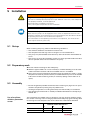
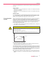
Mounting orientation
NOTE
Observe type-specific mounting orientations!
Pfeiffer Vacuum CompactTurbo™ pumps may only be installed in specific mounting
orientations. Impermissible mounting orientations can result in contamination of the
process vacuum or damage to the pump.
Î Pay attention to the properties code after the model designation on the name plate!
360°
180°
Fig. 3: Permissible installation orientati- Fig. 4: Installation orientations for turboons for standard versions
pumps with "Y" in their properties
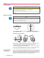
Horizontal mounting orientation
H
VV
VV
20˚ max
VV
Î For horizontal installation, the fore-vacuum flange must point vertically downward (± 20°), since otherwise the turbopump can be contaminated.
Î Support pipes in front of the pump or remove them. No force from the pipe system may be exerted on the braced turbopump.
The maximum axial loading capacity of the high vacuum flange is 500 N (equals
50 kg). A one-sided load on the high vacuum flange is not permitted.
Installing the high
vacuum flange
10
In the case the rotor is suddenly blocked, the torques arising from the system and
the high vacuum flange must be absorbed. Only the components listed in the following can be used to fasten the turbo pumps to the high vacuum flange. The components for installing the turbo pumps are special designs of Pfeiffer Vacuum. Observe the minimum strength of 170 N/mm2 for the flange material.
Installation
NOTE
Possible damage to the pump
If a pump with an ISO-K flange is fastened to a vacuum chamber with an ISO-F flange
or if ISO-KF flanges are used, sudden blocking of the rotor can result in twisting
despite proper installation.
Installation of ISO-K
flange with ISO-K
flange
For the installation of the flange connections the following components are available:
Connection nominal
diameter
DN 100 ISO-K
Designation
Pieces Ordering No.
Centering ring (coated)
1
PM 016 210-U
Centering ring (coated) with
1
splinter shield
PM 016 211-U
Centering ring (coated) with
1
protective screen
PM 016 212-U
Bracket screw
PF 300 110-T
6
Î Mind that the sealing surfaces are not damaged.
Î Flange the turbopump according to the drawing and together with the component parts in the mounting material kit.
Î Use the required number of bracket screws.
Î Tighten the bracket screws crosswise in three steps.
Î Tightening torque: 5, 15, 25 ±2 Nm
Installation of ISO-K
flange with ISO-F
flange
For the installation of the flange connections the following components are available:
Connection nominal
diameter
DN 100 ISO-K
DN 100 ISO-F
Designation
Pieces Ordering No.
Centering ring (coated)
1
PM 016 210-U
Centering ring (coated) with
1
splinter shield
PM 016 211-U
Centering ring (coated) with
1
protective screen
PM 016 212-U
Claw grip
PF 301 100-T
8
Î Mind that the sealing surfaces are not damaged.
Î Flange the turbopump according to the drawing and together with the component parts in the mounting material kit.
Î Use 8 claw grips.
Î Tighten the claw grips crosswise in three steps.
Î Tightening torque: 3, 10, 16 ±1 Nm.
Installation of CFflanges
NOTE
Preservation of sealing capacity
Observe the following to preserve sealing capacity:
Î Touch seals only with gloves.
Î Make sure sealing lips are undamaged.
11
Installation
The connection types for installation of CF to CF flange are "stud screw and pocket
hole" as well as "hex screw and through hole". The following elements are required:
• A set of mounting material for the respective type of connection
• A copper seal
• A protective screen or splinter shield can optionally be used
Nominal connection
diameter
DN 100 CF-F
Designation
Ordering no.
Hexagon bolt M8 with washer and
nut (25 pieces)1)
PF 505 003-T
Stud screw M8 with washer and
nut (25 pieces)1)
PF 507 003-T
Copper seal (10 pieces)
1)
PF 501 410-T
Copper seal, silvered (10 pieces)1)
PF 501 510-T
Splinter shield2)
PM 016 315
Protective screen2)
PM 016 336
1)
number of pieces in bracket is the delivery quantity
2)insert in the high vacuum flange with the clamping lugs towards the pump
52
Stud screw and pocket hole
Î If used: Insert protective screen or splinter shield with the clamping lugs downward into the high vacuum flange.
Î Place the seal exactly in the hollow.
Î Connect the flange using 16 stud screws (M8) with washers and nuts and tighten circularly with a torque of 22 ±2 Nm. After this, check the torque, since flowing of the sealing material may make it necessary to tighten the screws.
55
Hexagon screw and through hole
12
Î If used: Insert protective screen or splinter shield with the clamping lugs downward into the high vacuum flange.
Î Place the seal exactly in the hollow.
Î Connect the flange using 16 hex screws (M8) with washers and nuts and tighten
circularly with a torque of22 ±2 Nm. After this, check the torque, since flowing of
the sealing material may make it necessary to tighten the screws.
Installation
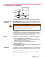
5.4 Connections to the turbopump
H
TC 600
RS 485
REMOTE
F
HEAT/TMS
VENT
FV PUMP
FAN
VV
Fig. 5: Connection designations for turbopumps with electronic drive unit TC 600
Connecting the forevacuum side
Recommendation: As backing pump, use a dry-compressing diaphragm pump or
rotary vane pumps from the Pfeiffer Vacuum programme. The backing pump must
generate a vacuum pressure of ≤ 5 mbar.
WARNING
Damage to health due to poisonous gases
Process gases can damage health and contaminate the environment.
Î Safely guide away the gas emission from the backing pump!
Î Observe all safety recommendations of the gas producer.
Î With rigid pipe connections: Install bellows for attenuation of vibrations in the
connection line.
Î Connect the fore-vacuum line with small-flange components or threaded hose
couplings. Do not narrow the free cross section of the fore-vacuum flange!
Î The backing pump is connected electrically via a relay box. Insert the control line
of the relay box into the "FV PUMP" connection of the TC 600 .
Cooling
Pfeiffer Vacuum turbopumps must be cooled by means of air or water cooling.
• When operating the pump with more than 50 % of the maximum gas load,
sealing gas must be used to ensure rotor cooling.
• In case of increased backing pressure (> 0.1 mbar) and/or operation with gas
loads, either air or water cooling may be used.
• Generally use water cooling if the ambient temperature is > +35 °C.
Î Connect air cooling for the corresponding pump type in accordance with the accessory's operating manual.
Î Connect water cooling for the corresponding pump type in accordance with the
accessory's operating manual.
Venting valve
The TVF 005 venting valve is used for automatic flooding in case of shut-down or
power failure. The maximum permissible pressure at the venting valve is 1.5 bar
absolute.
Installation of the venting valve
Î Unscrew the venting screw from the venting connection of the turbopump.
Î Screw in the venting valve with seal ring.
13
Installation
Electrical connection
Î Plug the control lead of the venting valve in accordance with the accessory’s
operating instructions.
Î Select the venting mode of the venting valve via the DCU, HPU or serial interface
RS485.
Casing heating unit
The turbopump and vacuum chamber can be heated to reach the final pressure
more quickly. Use of a casing heating unit makes sense only for pumps with the
high vacuum flange in stainless steel design. The heating duration depends on the
degree of contamination as well as the final pressure to be reached and should be
at least 4 hours.
CAUTION
Dangerous excess temperatures
Process-related high temperatures can result in impermissible excess temperatures
and thus damage to the turbopump.
Î Always use water cooling when a casing heating unit is used.
WARNING
Danger of burns
High temperatures arise when the turbopump or vacuum chamber are baked out. As a
result, there is a danger of burns from touching hot parts, even after the housing heater is switched off!
Î Thermally insulate heating sleeve, pump housing and vacuum chamber, if possible
during installation.
Î Do not touch heating sleeve, pump casing and vacuum chamber during bake out.
Î Connect the casing heating for the corresponding pump type in accordance with
the accessory's operating manual.
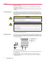
Sealing gas valve
Only pumps with the pump designation P (see rating plate) are equipped for connection of sealing gas. The turbopump must be operated with sealing gas to protect it, such as in the case of corrosive or dusty processes. The connection is made
via a sealing gas valve.
3
3a
3b
3c
3d
3e
H
3d
3e
Pump lower part
Sealing gas connection
Locking screw
O-ring
Sealing gas valve
O-ring
G
3b 3c
3a
3
Fig. 6: Connecting the sealing gas valve
Î Unscrew the screw plug with sealing ring out of the sealing gas connection of
the turbopump.
Î Screw the sealing gas valve with seal ring into the purge gas connection.
Î Obtain details on adjusting the sealing gas quantity from the corresponding
operating manual.
14
Installation
• When operating the pump with more than 50 % of the maximum gas load,
sealing gas must be used to ensure rotor cooling.
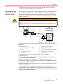
Connecting the electronic drive unit to
the power supply
The turbopumps CompactTurbo™ TMH/U 261 form a single unit with the electronic drive unit. For voltage supply, use only Pfeiffer Vacuum power supplies (e.g.
TPS 200 or DCU 200). Use other power supplies only after consultation with Pfeiffer Vacuum and comparison with valid specifications (specifications of the power
supplies on request).
WARNING
Danger of electric shock
In case of defect, the parts connected to the power supply are under voltage.
Î Always keep the mains connection freely accessible so you can disconnect it at any
time.
H
I
O
S1
8c
8a
X1
X
X2
X2
X4
8b 8c
X4
8
98
Fig. 7: TC 600 connection to power supply TPS or DCU, installation drawing for shielded cable
8Electronic drive unit
X
Power supply unit TPS or DCU
8a
Connecting cable TC 600 - TPS/DCU
X1
Mains connection TPS/DCU
8b
Screw
X2
Connection connecting cable - TPS/DCU
8c
Screw with lock washer
X4
Connection connecting cable - TC
98
Remote plug
S1
Switch ON/OFF
Î Unscrew the screw with lock washer 8c from the TC 600 (below
connection X4).1)
Î Insert the X4 plug on the 8a connection cable into the X4 connection on the
TC 600 and screw in the 8b screw.
Î Fasten the X4 plug to the TC 600 with a screw and lock washer 8c.1)
Î Connect the X2 plug on the 8a connection cable to the TPS 200/DCU 200 power
supply pack at the X2 connection.
Î Fasten the X2 plug to the power supply with a screw and lock washer 8c (included with the cable).1)
1)
Only for PM 051 843 -T shielded connection cable (see p. 33, chap. 12).
After operating voltage is applied, the TC 600 performs a self-test to check the supply voltage. The supply voltage for the turbopumps TMH/U 261 is 48 VDC ± 5% in
accordance with standard EN 60 742.
15
Installation
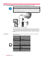
5.5 Connecting Pfeiffer Vacuum display and control units or PC
NOTE
Observe the connection instructions!
On delivery turbopumps with TC 600 are set up for operations with "Remote Control".
Î Before operating with DCU, HPU or PC the 15-pole D-Sub connector (remote plug)
must be removed from the TC 600.
USB/RS485-converter
RS-232
DCU 100-600
TIC 001
RS-485
HPU 001
TC 600
DCU 001
Fig. 8: Connecting the serial interface RS485
An external operating part (DCU or HPU 001) or an external computer can be connected via the connection with the designation "RS485" on the electronic drive
unit. The interface is securely separated galvanically from the maximum occurring
supply voltage of the TC 600. The electrical couplings are optically decoupled internally.
Connections
The connection of a RS232- oder USB-interface is possible via a TIC 001 or the
USB/RS485-converter.
1 .... 8
16
Designation
Value
Serial interface
RS485
Baud rate
9600 Baud
Data file word length
8 bit
Parity
keine (no parity)
Start bits
1
Stop bits
1..2
Pin
Assignement
1
not connected
2
+24 V output ladable with ≤ 210 mA
3
not connected
4
not connected
5
RS485: D+
6
Gnd
7
RS485: D-
8
not connected
Installation
Cross-linking via the
connection RS485
TIC 001/
USB/RS485-converter
TC
D+
D-
TC
D+
D-
D+
D-
D+
D-
RS 485
CAUTION
Danger of electric shock
The insulation measures of the bus system are designed only for use with safety extralow voltage.
Î Connect only suitable devices to the bus system.
Î The connections must be made in accordance with the specification of the interface RS485.
Î Connect all units with D+ (pin 5 / RS485) and D- (pin 7 / RS485) to the bus.
• The group address of the TC 600 is 960.
• All units connected to the bus must have differing serial interface addresses (parameter 797).
• All switched on remote functions have priority over the serial interface functions.
• Refer to the component operating instructions for detailed information concerning operation procedures and electrical data of the interface RS485.
NOTE
Connection to an external bus system
The integration into an external bus system (e.g. Profibus DP, DeviceNet) is possible
via connection gateway TIC 250 or TIC 260. Thus a synchronous use of interface
RS485 on the TC 600 is not possible.
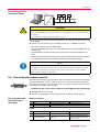
5.6 Connecting the remote control
8
15
1
9
Remote control options are provided via the 15-pole D-Sub connector with the designation ”REMOTE“ on the TC 600. The inputs 2 - 6 are activated by connecting
them with +24 V at Pin 1 (active high) (see p. 19, chap. 5.7). When connecting supply voltage the turbopump is started.
• On delivery: Pin 1, Pin 2, Pin 3 and Pin 4 are bridged in the remote plug.
Î Shielded cable must be used.
Î Connect the shielding on the plug side for the TC 600 to the TC housing.
Pin assignment and
function of the remote plug
Reference voltage
Pin Function
1
+24 V
Reference voltage level for all remote in and outputs
10
Ground
Ground potential for all remote in- and putputs
Inputs
Pin Function
Open (low)
Closed (high)
2
Venting release
Venting blocked
Venting released
3
Motor turbopump
Motor off
Motor on: the turbopump is
driven, current flows through
the motor coils
17
Installation
Pin Function
Open (low)
Closed (high)
4
Pumpstand aus
Pumping station on: the turbopump is driven, backing pump
control via relay box, the air
cooling unit runs
Heizung aus
Heating on: the heating is switched on once the rotation
switchpoint is attained. The
heating is switched off, if the
rotation switchpoint is not
attained
Pumping station
Heating
5
Option: Sealing gas conSealing gas valve closed
nection control1)
Sealing gas valve open
Reset
Reset: by supplying a pulse
(T< 2s) with an amplitude of
24V a malfunction acknowledgement can be processed
The turbopump is controlled
to 66% of its nominal rotation
speed
6
Standby
Standby off
7
Rotation speed setting
mode
The rotation speed can be
Rotation speed setting mode is modified by feeding a PWM
off
signal to this pin or via
RS4851)
1)
The option must be set via serial interface RS485 (refer to operating instructions PM 0547 BN,
Pumping Operation With DCU)
Outputs
Pin Function
Open (low)
Closed (high)
8
Switching output 1
Rotation speed switchpoint
not attained
Rotation speed switchpoint
attained; output can be loaded
with 24 V/50 mA
9
Switching output 2
Collective malfunction message
failure-free operation; output
can be loaded with 24 V/50 mA
11
Contact output 1
12
Contact output 1
Rotation speed switchpoint
not attained
contact2) between Pin 11 and
Pin 12 is closed, if the rotation
switchpoint is exceeded
13
Contact output 2
14
Contact output 2
Collective malfunction message
contact2) between Pin 13 and
Pin 14 is closed at failure-free
operation
15
Analog output
1)
Output voltage is proportional to the rotation speed: 0 - 10 VDC
= 0 - 100% *fend / load R ≥ 10 kΩ (optional current/power)1)
The option must be set via serial interface RS485 (refer to operating instructions PM 0547 BN,
Pumping Operation With DCU)
2)
The following technical data are applicable for the contacts: Umax = 50 VDC, Imax = 1 A
18
Installation
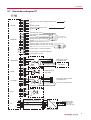
5.7 Connections diagram TC
TC 600
TC 750
1
2
3
4
5
6
7
8
1
2
3
4
5
6
7
8
RS 485
1
2
3
4
5
6
7
8
9
10
11
12
13
14
15
REMOTE
1
2
3
4
5
6
HEAT/TMS
VENT
1
2
3
4
5
6
FV PUMP
1
2
3
4
5
6
n.c.
+24 VDC* / max. 200 mA (supply voltage, DCU)
n.c.
n.c.
RS 485+/ (DO/RI)
GND* (mass connection, DCU)
RS 485- / (DO/RI)
n.c.
+24 VDC*/max. 50 mA
Venting release
Motor TMP
Pumping station
Heating / Reset (opt. sealing gas)
Standby
PWM on (touch relation 25 - 75 %)
Switching output 1 (24 VDC / max. 50 mA)
Switching output 2 (24 VDC / max. 50 mA)
GND*
Contact current:
max. 6 mA / contact
Contact output 1: Switch point attaind
Contact output 2: Collective malfunction
Analog output 0-10 VDC
Relay box
L
N
PE
PE
N
L'
Heating
Mains input, heating
115/208/230 VAC
HEATING
Venting valve
TVF 005
L
N
PE
PE
N
L'
Relay box
Mains input, pumping station
115/208/230 VAC
Connection, pumping station
Pumping station (Imax = 16 A)
1
2
3
4
5
6
FAN
M
Fan
X2
X4
n.c.
PE
1
2
3
Br
Protection conducter (PE)
Supply voltage, TC
Bl
GND
GY/YE
1
2
3
4
Mains input
power supply
(90 - 132 /
185 - 265) VAC
TPS XXX/DCU XXX
19
Operation
6
Operation
NOTE
Installation and operation of accessories
Pfeiffer Vacuum pumps can be equipped with a series of adapted accessories. The
installation, operation and maintenance of connected devices are described in detail in
the operating instructions of the individual components.
Î For information on the operating instructions of components, see "Accessories".
Î Use original accessory parts only.
CAUTION
Re-starting
The serviceability of the operating fluid without operation is a maximum of three years.
Before restarting after a shut-down of 3 years or longer, carry out the following work.
Î Replace the operating fluid reservoir.
Î Replace bearings.
Î Follow the maintenance instructions and inform Pfeiffer Vacuum.
WARNING
Danger due to open high vacuum flange
The rotor of the turbopump turns at high speed. If the high vacuum flange is open,
there is a danger of cut injuries and that the pump can be destroyed by objects falling
into it.
Î Never operate the pump with an open high vacuum flange.
6.1 Operation modes
The following operation modes are available:
• Operation without operating panel
• Operation via remote control unit
• Operation via RS485 with Pfeiffer Vacuum display and control units or PC
6.2 Commissioning
The following settings are permanently programmed in the TC 600 ex factory.
• Run-up time: 15 min
• Rotation speed switchpoint: 80%
• Automatic venting: 50%
Î Settings are possible via the RS485 on the TC 600 by using DCU, HPU or PC.
Î When water cooling is used: Open cooling water supply and check the flow.
Î Plug connecting cable between the TC 600 and the power supply.
20
Operation
S1
X1
X2
F1
F2
Switch ON/OFF
Mains connection
Connection TC 600
Fuse
Fuse
Fig. 9: Rear panel of power supply TPS
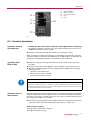
6.3 Function description
Operation without
operating unit
• On delivery: Pin 1, Pin 2, Pin 3 and Pin 4 are bridged in the remote plug.
• For operation without the control unit, the 15-pole D-Sub plug must be in the
"REMOTE" connection on the TC 600.
Î Switch on the supply voltage with switch S1 on the power supply.
When air cooling is used: the cooling fan is switched on automatically. Once the
self test has been successfully completed on the TC 600 (approx. 10 seconds), the
turbopump and the backing pump - if connected - begin to operate.
Operation with
DCU or HPU
Î Switch on the supply voltage with switch S1 on the power supply or on the
DCU 200.
Î Settings are possible via the RS485 on the TC 600 by using DCU, HPU or PC.
Î Observe the following documents for operation with Pfeiffer Vacuum display
and control units:
• Operating instructions DCU
• Operating instructions HPU 001
• Pumping operations with DCU
NOTE
Observe the connection instructions!
On delivery turbopumps with TC 600 are set up for operations with "Remote Control".
Î Before operating with DCU, HPU or PC the 15-pole D-Sub connector (remote plug)
must be removed from the TC 600.
Operation with remote control
Remote control options are provided via the 15-pole D-Sub connector with the designation ”REMOTE“ on the TC 600. The inputs 2 - 6 are activated by connecting
them with +24 V at Pin 1 (active high) (see p. 19, chap. 5.7). When connecting supply voltage the turbopump is started.
Î Remove the remote plug from the TC 600 and connect a remote control unit. Pin
assignment of the connector according to table (see p. 17, chap. 5.6).
Venting release (option)
Venting released (automatic venting)
Venting blocked (no venting)
21
Operation
• Settings are possible via the RS485 on the TC 600 by using DCU, HPU or PC.
Turbopump motor
After the pumping station is switched on and the self-test successfully completed
(duration approx. 10 seconds), the turbopump is set into operation. During operation, the turbopump can be switched off and on again, while the pumping station
remains switched on. The turbopump is not vented thereby.
Pumping station
Connected pumping station components (e.g. backing pump, venting valve, air
cooling) are triggered and, with "turbopump motor" input simultaneously activated, the turbopump is set into operation after a successfully completed self-test (duration approx. 10 seconds).
Heating/Reset
Heating (Option)
After the rotation speed switchpoint is reached, the heating is switched on and
switched off again when this point is fallen below. A purge gas valve can optionally
be triggered here.
Reset
The heating input is assigned a dual function ((see p. 17, chap. 5.6), Point 5 ”Reset“).
Standby
With the use of "Standby", the turbopump can be operated either at 66% of the
nominal rotation speed (Standby ON) or at the nominal rotation speed (Standby
OFF).
Speed actuation mode via PWM input
A pulse-width-modulated (PWM) signal permits setting the speed within the range
of 20 - 100% of the nominal rotation speed.
U
20%*fend
Base frequency 100 Hz ±20%
Amplitude 24 V max.
Key ratio 25 - 75%
100%*fend
max. +33V
min. +13V
max. +7V
min. -33V
T
0
TPWM*25%
TPWM*75%
T PWM = 10ms (1±20%)
f PWM =100Hz (1±20%)
If a signal is present, the pump runs up to the final rotation speed. Optionally, a
PWM adapter box for turbopumps can be connected.
Switch outputs
The switch outputs 1 and 2 can be loaded with a maximum 24 V / 50 mA per output.
The following functions are assigned to the switching outputs:
• Switching output 1: Active high after the rotation speed switchpoint is reached.
The switch-point for the turbopump is set at 80% of the nominal rotation speed.
It can, for example, be used for a "pump operational" message.
• Switching output 2: Active low in case of malfunction(common error message).
22
Operation
A relay is connected between Pin 10 (earth) and the respective switching output Pin
8 or Pin 9.
Contact outputs
• Relay contact 1: The contact between Pin 11 and Pin 12 is closed, if the rotation
switchpoint is exceeded.
• Relay contact 2: The contact between Pin 13 and Pin 14 is closed at failure-free
operation.
Analogue output
Over the analog output, a speed-proportional voltage (0-10 VDC equals 0 - 100 %
*fend) can be picked up (load R ≥ 10 kΩ). Additional functions (optionally current/
power) can be assigned to the analog output via DCU, HPU or PC.
With gas load and high rotation speed, the rotor heats up strongly. To avoid overheating, the TC 600 has implemented a power-rotation speed-characteristic,
whereby the pump can be operated at every rotation speed with the maximum allowable gas load without danger of damage. The maximum power depends on the
gas type. Two characteristics are available in order to completely exhaust the
pump's capacity for each gas type.
• "Gas mode 0" (factory setting) for gases with the molecular mass ≥ 40, e.g. Ar
• "Gas mode 1" for all lighter gases.
CAUTION
Danger of the pump being destroyed
Pumping of gases with the molecular mass ≥ 40 in the wrong gas mode can lead to
destruction of the pump.
Î Ensure the gas mode is correctly set.
Î Contact Pfeiffer Vacuum before using gases with a greater molecular mass.
Leistung
Gas-type-dependent
operation
D
B
D-C = Gas mode «0»
B-A = Gas mode «1»
Frequenz
Hochlauf
A
C
fnom
Fig. 10: Gas mode power characteristic
• Settings are possible via the RS485 on the TC 600 by using DCU, HPU or PC.
• Vertex of the power characteristic (see p. 34, chap. 13)
The turbopump is always run up under maximum power in order to minimise the
run-up time. When the set rotation speed is achieved, the chosen power characteristic is automatically switched over. When the gas-type-dependent maximum power is exceeded, the rotation speed of the turbopump is reduced until an equilibrium
between permissible power and gas friction is attained.
Î To avoid rotation-speed fluctuations, Pfeiffer Vacuum recommends setting the
equilibrium frequency or a somewhat lower frequency in speed actuation operation.
23
Operation
6.4 Monitoring of the operation conditions
Operating mode display via LED
LEDs in the front panel of the TC 600 show basic operating conditions of the turbopump and TC. A differentiated malfunction and warning display is possible only
for operation with DCU or HPU.
LED green
Temperature monitoring
LED red
Cause
glows
power supply is o.k.
function ”pumping station on“ is carried out
flashes short
(1/12s active)
power supply is o.k.
pumping station is off
blinks
(1/2s active)
voltage drop; mains power failure
glows
Collective malfunction, e.g.
– run-up time failure
– excess temperature of the pump
– switching output 2 active (low)
blinks
(1/2s active)
Warning, e.g.
– ground leak of the supply voltage
– mains power failure
The motor current is reduced in case of impermissible motor temperature or impermissibly high housing temperature. This can cause the motor to fall below the
set rotation speed switchpoint and so result in switching off of the turbomolecular
pump.
6.5 Switching off and venting
Switching off
After the turbopump is switched off, it must be vented to avoid contamination due
to particles streaming back from the fore-vacuum area.
Î Close the fore-vacuum line. Switch off the backing pump or close a fore-vacuum
valve.
Î Switch off the turbopump on the control unit or via remote control.
Î Venting (possibilities, see below)
Î For water cooling: Shut off the water supply.
Venting
Manually Venting
Î Open the venting screw (included) in the venting connection of the pump about
one turn.
Venting with venting valve TVF 005
Î Enable venting via the functions of the electronic drive unit.
Î Settings are possible via the RS485 on the TC 600 by using DCU, HPU or PC.
Venting frequency Switch off the pumping station Mains power failure1)
50% of the final
rotation speed
1)
Venting valve opens for 3600 s (1 h, Venting valve opens for 3600 s (1 h,
works setting)
works setting)
When mains power is restored the venting procedure is aborted.
Basic information for the rapid venting
Venting of the vacuum chamber in two steps. Ask for details on individual solutions
from Pfeiffer Vacuum.
Î Vent for 20 seconds at a rate of pressure rise of max. 15 mbar/s.
– The valve cross section for the venting rate of 15 mbar/s must be adapted to
the size of the vacuum chamber.
24
Maintenance / replacement
– For small vacuum chambers, use the Pfeiffer Vacuum TVF 005 venting valve.
Î Then vent with an additional venting valve of any desired size.
7
Maintenance / replacement
WARNING
Contamination of parts and operating fluid by pumped media is possible.
Poisoning hazard through contact with materials that damage health.
Î In the case of contamination, carry out appropriate safety precautions in order to prevent danger to health through dangerous substances.
Î Decontaminate affected parts before carrying out maintenance work.
NOTE
Disclaimer of liability
Pfeiffer Vacuum accepts no liability for personal injury or material damage, losses or
operating malfunctions due to improperly performed maintenance. The liability and
warranty entitlement expires.
7.1
Maintenance intervals and responsibilities
•
•
•
•
Clean the turbopump externally with a lint-free cloth and little industrial alcohol.
You can replace the operating fluid reservoir and electronic drive unit yourself.
Change the operating fluid reservoir at least every 3 years.
Change the turbopump bearing at least every 3 years.
– Contact Pfeiffer Vacuum Service.
• Clarify shorter change intervals for extreme loads or impure processes with
Pfeiffer Vacuum Service.
• For all other cleaning, maintenance or repair work, please contact your Pfeiffer
Vacuum service location.
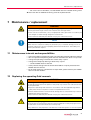
7.2
Replacing the operating fluid reservoir
WARNING
Poisoning hazard through contact with materials that damage health.
The operating fluid reservoir and parts of the pump may contain toxic substances from
the pumped media.
Î Dispose of operating fluid reservoir in accordance with the applicable regulations.
Safety data sheet on request or under www.pfeiffer-vacuum.net
Î Prevent health hazards or environmental damage due to contamination by means of
appropriate safety precautions.
Î Decontaminate affected parts before carrying out maintenance work.
CAUTION
Pay attention to pump types
The procedure for changing the lubricant reservoir depends on the pump type. Incorrect execution can result in destruction of the pump.
Î Pay attention to the properties code after the model designation on the name plate!
25
Maintenance / replacement
NOTE
Lubricant filling
The lubricant reservoir is sufficiently filled with TL 011 lubricant.
Î Do not add additional lubricant.
Standard version
Î Turn off the vacuum pump, vent to atmospheric pressure and allow to cool, if
necessary.
Î Remove the vacuum pump from the system, if necessary.
Î Close the flange openings by using the original protective covers.
Î Turn the turbopump over onto the closed high vacuum flange.
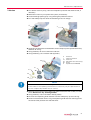
E
7
6
Î Screw out the end cover on the bottom of the turbopump with special tool E. Pay
attention to O-ring.
Î Using tweezers, lift out the lubricant reservoir.
6
7
48
E
End cover
Lubricant reservoir
O-ring
Special tool PV M40 569
7
48
6
E
Î Remove impurities from the turbopump and the end cover with a clean, lint-free
cloth. Do not use any cleaning fluids!
Î Push the new operating fluid reservoir into the turbopump up to the O-ring.
Î Screw in the end cover with O-ring. The operating fluid reservoir is brought into
the correct axial position with the end cover.
26
Maintenance / replacement
Y Version
Î Turn off the vacuum pump, vent to atmospheric pressure and allow to cool, if
necessary.
Î Remove the vacuum pump from the system, if necessary.
Î Close the flange openings by using the original protective covers.
Î Turn the turbopump over onto the closed high vacuum flange.
E
7
6
Î Screw out the end cover on the bottom of the turbopump with special tool E. Pay
attention to O-ring.
Î Using tweezers, lift out the lubricant reservoir.
Î Using tweezers, pull out Porex rods (8 pieces).
6
7
7a
7b
48
E
7a
End cover
Lubricant reservoir
Porex rod
Felt washer (for service only)
O-ring
Special tool PV M40 569
6
7
48
7a
7b
E
NOTE
Felt washer in the lubricant reservoir packet
The felt washer in the operating fluid reservoir is necessary only for special service
work and is replaced by Pfeiffer Vacuum Service.
Î Remove impurities from the turbopump and the end cover with a clean, lint-free
cloth. Do not use any cleaning fluids!
Î Using tweezers, insert new Porex rods (8 pieces).
Î Push the new operating fluid reservoir into the turbopump up to the O-ring.
Î Screw in the end cover with O-ring. The operating fluid reservoir is brought into
the correct axial position with the end cover.
27
Maintenance / replacement
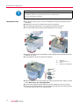
7.3
Replacing the electronic drive unit
WARNING
Danger of electric shock
Even after mains power is switched off, the subsequently running turbopump delivers
voltages > 50 V eff.. There is a danger of electric shock when touching open contacts
on conducting parts.
Î Never separate the electronic drive unit from the pump when the mains power is
connected or the rotor is running.
Î Wait for the turbopump to reach complete standstill.
Î Disconnect the electronic drive unit from the mains.
NOTE
Operating parameters of the electronic drive unit
The factory operating parameters are always preset with replacement shipments.
Î The use of a HPU enables the storing and the reuse of an existing parameter record.
Î Reset any individually changed application parameters.
Î Refer to the manual "Pumping operations".
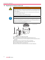
8
9
9
Electronic drive unit
Allen head screw
8
Fig. 11: Assembly / disassembly of the TC 600
Î Do not exercise any mechanical load on the electronic drive unit.
Î Turn off the vacuum pump, vent to atmospheric pressure and allow to cool, if
necessary.
Î Remove the vacuum pump from the system, if necessary.
Î Unscrew Allen head screws (2 x) from the electronic drive unit.
Î Pull the electronic drive unit off the pump.
Î Screw on and connect new electronic drive unit to the turbopump.
28
Decommissioning
8
Decommissioning
8.1 Shutting down for longer periods
WARNING
Contamination of parts and operating fluid by pumped media is possible.
Poisoning hazard through contact with materials that damage health.
Î In the case of contamination, carry out appropriate safety precautions in order to prevent danger to health through dangerous substances.
Î Decontaminate affected parts before carrying out maintenance work.
If the turbopump should be shut down for longer than a year:
Î Remove the vacuum pump from the system, if necessary.
Î Change the operating fluid reservoir.
Î Close high vacuum flange of the turbopump.
Î Evacuate turbopump via the fore-vacuum flange.
Î Vent turbopump via the venting connection with dry air or inert gas.
Î Close the flange openings by using the original protective covers.
Î Close further connection ports by using the corresponding protective covers.
Î Place pump upright on rubber feet.
Î Storage the pump only indoors with an ambient temperature between -25 °C
and +55 °C.
Î In rooms with moist or aggressive atmospheres, the turbopump must be air-seeled in a plastic bag together with a bag of dessicant.
8.2 Re-starting
CAUTION
Re-starting
The serviceability of the operating fluid without operation is a maximum of three years.
Before restarting after a shut-down of 3 years or longer, carry out the following work.
Î Replace the operating fluid reservoir.
Î Replace bearings.
Î Follow the maintenance instructions and inform Pfeiffer Vacuum.
Î Check turbopump for contamination and moisture.
Î Clean the turbopump externally with a lint-free cloth and little industrial alcohol.
Î If necessary, have Pfeiffer Vacuum Service clean the turbopump completely.
Î If necessary, have the bearings replaced. Take into account the total running
time.
Î Change the operating fluid reservoir.
Î Installation and commissioning in accordance with the operating instructions
(see p. 9, chap. 5).
8.3 Disposal
Products or parts thereof (mechanical and electrical components, operating fluids,
etc.) may cause environmental burden.
Î Safely dispose of the materials according to the locally applicable regulations.
29
Malfunctions
9
Malfunctions
If malfunctions on the pump occur, you will find possible causes and instructions
for repair in the following table.
9.1 Rectifying malfunctions
Problem
Possible causes
Remedy
•
Electrical supply interrupted
Ö Check fuses in the power supply
Ö Check plug contacts on the power supply
pack
Ö Check supply lines of the power supply pack
Ö Check output voltage (48 VDC) on the X2 of
the power supply pack
Ö Check plug contacts on the power supply
pack
•
Operating voltage incorrect
Ö Apply correct operating voltage
Ö Observe name plate
•
No operating voltage applied
Ö Supply the operating voltage
•
TC 600 defective
Ö Exchange TC 600 .
Ö Contact Pfeiffer Vacuum Service
•
Pin 1-3 and 1-4 on the remote plug not Ö Connect Pin 1-3 and 1-4 on the remote plug
connected
•
Voltage drop in the cable
Ö Use a suitable cable
•
Backing pressure too high
Ö Ensure function and suitability of the backing pump
•
Leak
Ö Perform leak detection
Ö Check gaskets and flange fasteners
Ö Eliminate leaks
Pump will not start up; none of the
built-in LEDs on the TC 600 lights up
Pump will not start up; green LED on
the TC 600 is flashing
Pump does not attain the nominal rota- •
tion speed within the specified starting •
time
•
Pump not achieving the end pressure
Unusual noises during operation
Gas load too high
Ö Reduce process gas feed
Rotor runs hard, defective bearing
Ö Check bearing for noise development
Ö Contact Pfeiffer Vacuum Service
Starting time set too low
Ö Extend starting time via DCU, HPU or PC
•
Thermal overload:
– Lack of cooling
– Backing pressure too high
– Ambient air temperature too high
Ö Reduce thermal load
– Ensure adequate cooling
– Lower backing pressure
– Adjust ambient conditions
•
Pump is dirty
Ö Bake out pump
Ö Cleaning in case of heavy contamination
– Contact Pfeiffer Vacuum Service
•
Vacuum chamber, pipes or pump leak Ö Leak detection starting from the vacuum
chamber
Ö Eliminate leaks
•
Bearing damage
Ö Contact Pfeiffer Vacuum Service
•
Rotor damaged
Ö Contact Pfeiffer Vacuum Service
•
Splinter shield or protective screen
loose
Ö Correct seat of the splinter shield or protective screen
Ö Observe installation notes
•
Common error
Ö Reset through mains off/on switch
Ö Reset via Pin 5 on the "REMOTE" connection
Ö Differentiated malfunction display via DCU
or HPU possible1)
Ö Contact Pfeiffer Vacuum Service
•
Warning:
– Earthing of the supply voltage
– Power failure
Ö Differentiated malfunction display via DCU
or HPU possible1)
Ö Check partial mains voltage
Ö Check partial mains voltage for earthing
Ö Check mains power supply to the power adapter
Red LED on the TC 600 lights up
Red LED on the TC 600 is flashing
1)If
30
no Pfeiffer Vacuum control panel is available, please contact Pfeiffer Vacuum Service
Service
10 Service
Pfeiffer Vacuum offers first-class service!
•
•
•
•
Operating fluid and bearing change on the spot by Pfeiffer Vacuum FieldService
Maintenance / repair in the nearby ServiceCenter or ServicePoint
Fast replacement with exchange products in mint condition
Advice on the most cost-efficient and quickest solution
Detailed information, addresses and forms at: www.pfeiffer-vacuum.net (Service).
Maintenance and repair in the Pfeiffer Vacuum ServiceCenter
The following steps are necessary to ensure a fast, smooth servicing process:
Î RMA form and declaration of contamination.1)
Î Fill out the RMA form and send it by fax or e-mail to your service address.
Î Include the RMA confirmation from Pfeiffer Vacuum with your shipment.
Î Fill out the contamination declaration and include it in the shipment (required!).
Î Dismantle all accessories.
Î Drain the operating fluid (applies for turbopumps in corrosive gas version or
with suction performance > 550 l/s)
Î Leave electronic drive on the pump.
Î Close the flange openings by using the original protective covers.
Î If possible, send pump in the original packaging.
Contaminated vacuum pumps
No units will be accepted if they are contaminated with micro-biological, explosive
or radioactive substances. “Hazardous substances” are substances and compounds in accordance with the hazardous goods directive (current version). If
pumps are contaminated or the declaration of harmlessness is missing, Pfeiffer
Vacuum performs decontamination at the shipper's expense.
Sending of contaminated pumps or devices
Î Neutralise the pump by flushing it with nitrogen or dry air.
Î Close all openings airtight.
Î Seal the pump or unit in suitable protective film.
Î Return the pump/unit only in a suitable and sturdy transport container and send
it in while following applicable transport conditions.
Exchange unit
The factory operating parameters are always preset with exchange units. If you use
changed parameters for your application, you have to set these again.
Service orders
All service orders are carried out exclusively according to our repair conditions for
vacuum units and components.
1)
Return material authorization under www.pfeiffer-vacuum.net
31
Spare parts TMH/U 261
11 Spare parts TMH/U 261
Item Designation
Size
Order Number
6
End cover
M40 x 1
PM 003 619 A
7
Lubricant reservoir
Pieces Order Qty
1
PM 063 265 -T
incl. O-ring
PM 063 266 -T
incl. 8 x Porex rod (7a), O1
ring, felt washer
7
Lubricant reservoir ("Y")
8
Electronic drive unit TC 600
48
O-ring
53
Sealing plugs
P 4098 582 FA
98
Remote plug
PM 051 793 -X
38 x 3
Notes
1
PM C01 720
1
P 4070 621 PV
1
4
Pin 1 to 4 bridged
TMH/U 261
1
TMH/U 261 Y
7a
7
6 48
53
8
98
7
Please also specify model number of the the rating plate when ordering accessories or spare parts.
32
Accessories
12 Accessories
Designation
Size
Order Number
Operating
instructions
DCU 200 power supply with Display Control Unit
200 W
PM C01 695
PM 0477 BN
PM 0547 BN
TPS 200 power supply for wall/
standard rail mounting
200 W
PM 041 813 -T
PM 0521 BN
TPS 201 power supply 19" rack
module 3HU
200 W
PM 041 819 -T
PM 0521 BN
Mains cable with safety plug
230 V, 3 m
P 4564 309 ZA
Mains cable with UL plug
115 V, 3 m
P 4564 309 ZE
Mains cable with UL plug
208 V, 3 m
P 4564 309 ZF
Notes
Order
Qty
Power supllies
Mains cable
Other lengths on
request
Connecting cable
TC 600 - TPS / DCU
3m
PM 051 103 -T
TC 600 - TPS / DCU, shielded
3m
PM 051 843 -T
Other lengths on
request
Control panel
DCU 001 Display Control Unit
PM 041 816 -T
PM 0477 BN
PM 0547 BN
HPU 001 Handheld Programming
Unit
PM 051 510 -T
PT 0101 BN
Accessories package for HPU
PM 061 005 -T
Components for venting
TTV 001 Air drier
PM Z01 121
PM 0022 BN
incl. Zeolite filling
TVF 005 Venting valve
24 V DC, G 1/8"
PM Z01 135
PM 0507 BN
closed without current
Venting flange
DN 10 ISO-KF
PM 033 737 -T
Circlip for venting flange
DN 10-15 ISO-KF
PF 102 016 -T
Heating jacket, safety plug
230 V,
PM 041 903 -T
Heating jacket, UL plug
208 V
PM 041 904 -T
PM 0542 BN
Water cooling required
Heating jacket, UL plug
115 V
PM 041 905 -T
24 V DC
PM Z01 252
PM 0543 BN
PM 016 040 -T
PM 0546 BN
PM 0369 BN
Components for heating
Components for cooling
Air cooling
Water cooling
TZK 400 Water cooling unit
230 V, 50 Hz
PM Z01 245
Dirt trap
G 3/8"
P 4161 300 2R
Fore-vacuum triggering
Relay box 1-phase
5A
PM 041 937 -T
Relay box 1-phase
20 A
PM 041 938 -T
TVV 001 Fore-vacuum valve
230 V, DN 16 ISO-KF
PM Z01 205
TVV 001 Fore-vacuum valve
115 V, DN 16 ISO-KF
PM Z01 206
PT 0030 BN
PM 0263 BN
Accessories, general
Sealing gas valve
M6 / DN 10 ISO-KF
PM Z01 142
Hose nipple, sealing gas valve
DN 16 ISO-KF-10
PF 144 020
PM 0229 BN
Vibration compensator
DN 100 ISO-K
PM 006 459 -X
Vibration compensator
DN 100 CF-F
PM 006 488 -X
PWM box rotation speed control
10 - 30 V DC
PM 051 028 -U
PM 0563 BN
Pfeiffer Vacuum protocol
RS232/RS485
TIC 001 Interface converter
RS232 in RS485
PM 051 054 -T
PM 0549 BN
PM 0488 BN
TIC 250 Profibus-DP gateway
PM 051 257 -T
PM 0599 BN
TIC 260 DeviceNet gateway
PM 061 166 -T
PT 0177 BN
USB/RS485 converter
Connection cable
TC 600 cover for IP 54
RS485/M12 in USB
3m
PM 061 207 -T
PM 051 726 -T
PM 051 327 -U
interface protocol
incl. CD-ROM
PT 0024 BN
Installation material, accessories for flange fastening (see p. 9, chap. 5.3).
33
Technical data
13 Technical data
Parameter
TMH 261 P
TMH 261 YP
TMU 261 P
TMU 261 YP
Flange (in)
DN 100 ISO-K
DN 100 CF-F
Flange (out)
DN 25 ISO-KF / G 1/4"
DN 25 ISO-KF / G 1/4"
Venting connection
G 1/8"
G 1/8''
Rotational speed ±2%
60000 rpm
60000 rpm
Run-up time
1.6 min
1.6 min
Ultimate pressure with rotary vane pump
< 1·10-7 mbar
< 5·10-10 mbar
Ultimate pressure with diaphragm pump
-7
< 1·10 mbar
< 1·10-8 mbar
Fore Vacuum max. for N2
10 mbar
10 mbar
Compression ratio for N2
>1·109
>1·109
Compression ratio for He
3·105
3·105
Compression ratio for H2
4
1,3·104
9
>1·109
1.4·10
Compression ratio for Ar
>1·10
Gas throughput at 0.1 mbar HV for N2
7 mbar l/s
Gas throughput at 0.1 mbar HV for He
6 mbar l/s
6 mbar l/s
Gas throughput at 0.1 mbar HV for H2
3.5 mbar l/s
3.5 mbar l/s
Gas throughput at 0.1 mbar HV for Ar
7 mbar l/s
7 mbar l/s
Gas throughput at full rotational speed for N2
7 mbar l/s
7 mbar l/s
Gas throughput at full rotational speed for He
9 mbar l/s
9 mbar l/s
Gas throughput at full rotational speed for H2
43 mbar l/s
43 mbar l/s
Gas throughput at full rotational speed for Ar
4 mbar l/s
4 mbar l/s
Pumping speed backing pump for the listed gas
throughputs at least
10 m3/h
10 m3/h
Pumping speed for N2
210 l/s
210 l/s
Pumping speed for He
220 l/s
220 l/s
Pumping speed for H2
175 l/s
175 l/s
Pumping speed for Ar
200 l/s
200 l/s
Cooling method, standard
Water, air
Water, air
Max. cooling water temperature
25 °C
25 °C
Cooling water consumption
100 l/h
100 l/h
Weight
6.1 kg
8.1 kg
Standby rotational speed
40000 1/min
40000 1/min
Sound pressure level
50 db (A)
50 db (A)
Ultimate pressure of the backing pump
<5 mbar
<5 mbar
Integral leak rate
<1·10-7 mbar l/s
<1·10-7 mbar l/s
Max. rotor temperature
90 °C
90 °C
Max. input heat capacity
8W
8W
Max. surrounding magnetic field
6 mT
6 mT
Fore vacuum max. for He
8 mbar
8 mbar
Fore vacuum max. for H2
4 mbar
4 mbar
Fore vacuum max. for Ar
10 mbar
10 mbar
Vertex of the power characteristics line: A
B
C
D
170/1000 W/Hz
170/1000 W/Hz
103/1000 W/Hz
170/760 W/Hz
170/1000 W/Hz
170/1000 W/Hz
103/1000 W/Hz
170/760 W/Hz
Lubricant
TL011
TL011
Max. ambient temperature with air cooling
35 °C
Power consumption housing heater
34
7 mbar l/s
35 °C
60 W
Operating voltage
48 ± 5% VDC
48 ± 5% VDC
Max. power consumption: pump
200 W
200 W
Power consumption, continous operation
170 W
170 W
Max. current consumption: pump
4.8 A
4.8 A
Current consumption, continous operation
4.1 A
4.1 A
IP 30
Protection class
IP 30
Temperature: Storage
-25 to +55 °C
-25 to +55 °C
Relative humidity (non dewing)
5 to 85 %
5 to 85 %
Technical data
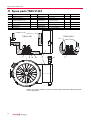
13.1 Dimension diagrams
82
60˚
M6
82
113.5
67
60˚
30˚
45˚
M6
M8
G
113.5
67
30˚
45˚
M8
G
DN 25 ISO-KF
14
Ø138.5
Ø119
DN 100 ISO-K
DN 100 CF-F
53.5
VV
48
F
VV
120
F
194.5
162.5
146
128.5
96.5
86.5
48
G
3
3
Fig. 12: TMH 261 P / YP, DN 100 ISO-K
14
H
120
194.5
162.5
146
128.5
96.5
86.5
H
G
104.2
125
53.5
Ø138.5
Ø119
M8
50
G1/8"
5
104.2
125
Ø8
F
5
M8
50
95
100
88.5
Ø8
F
G1/8"
33˚
33˚
88.7
VV
VV
58
58
95
100
DN 25 ISO-KF
Fig. 13: TMU 261 P / YP, DN 100 CF-F
35
Declaration of conformity
according to the EC directive:
• Machinery 2006/42/EC (Annex II, no. 1 A)
We hereby declare that the product cited below satisfies all relevant provisions
of EC directive "Machinery" 2006/42/EC.
In addition, the product cited below satisfies all relevant provisions of EC directive "Electromagnetic Compatibility" 2004/108/EC .
The agent responsible for compiling the technical documentation is Mr. Jörg
Stanzel, Pfeiffer Vacuum GmbH, Berliner Straße 43, 35614 Aßlar.
TMH 261 / TMU 261
Guidelines, harmonised standards and national standards and specifications
which have been applied:
DIN EN ISO 12100-1 : 2004
DIN EN ISO 12100-2 : 2004
DIN EN ISO 14121-1 : 2007
DIN EN 1012-2 : 1996
DIN EN 61010-1 : 2002
Signatures:
Pfeiffer Vacuum GmbH
Berliner Straße 43
35614 Asslar
Germany
(M.Bender)
Managing Director
(Dr. M. Wiemer)
Managing Director
CE/2010
Vacuum is nothing, but everything to us!
Turbopumps
Rotary vane pumps
Roots pumps
Dry compressing pumps
Leak detectors
Valves
Components and feedthroughs
Vacuum measurement
Gas analysis
System engineering
Service
Pfeiffer Vacuum Technology AG · Headquarters/Germany
Tel. +49-(0) 64 41-8 02-0 · Fax +49-(0) 64 41-8 02-2 02 · [email protected] · www.pfeiffer-vacuum.net