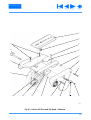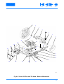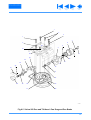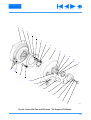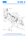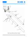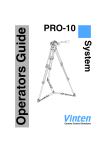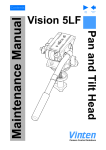
1
Contents Previous View Vision 250 Pan and Tilt Head Maintenance Manual Next Page Vinten Camera Control Solutions Contents First Page Previous Page Next Page Previous View Vision 250 PAN AND TILT HEAD 3525 MAINTENANCE MANUAL AND ILLUSTRATED PARTS LIST PUBLICATION PART No. 3525-9 ISSUE 1 Copyright Vinten Broadcast Limited 1999 All rights reserved throughout the world. No part of this document may be stored in a retrieval system, transmitted, copied or reproduced in any way including, but not limited to, photocopy, photograph, magnetic or other record without the prior agreement and permission in writing of Vinten Broadcast Limited. Vinten, Vision and Quickfit are registered trademarks of Vinten Broadcast Limited. 2 Contents First Page Previous Page Next Page Previous View Foreword This manual provides full and detailed maintenance and spare parts information for the Vinten® Vision® 250 pan and tilt head. WARNING!: Read the Safety Section on page 7 before using this pan and tilt head or attempting any adjustment or repair. It is recommended that this manual is read carefully and the illustrations studied prior to operating or servicing the pan and tilt head. Attention to the details contained herein will ensure that the pan and tilt head will operate efficiently with the minimum of attention over a long service life. Particular attention must be paid to cleaning, especially after use in adverse conditions. To order spare parts or to obtain further information, application should be made to Vinten Broadcast Limited or to your local distributor. NOTE: Information contained in this document is subject to change. Vinten Broadcast Ltd reserves the right, without notice, to make changes in equipment design or performance as progress in engineering, manufacturing or technology may warrant. 3 Contents First Page Previous Page Next Page Previous View Notes to readers This is the on-line version of ‘Vision 250 Pan and Tilt Head Maintenance Manual’ (3525-9). Readers should be aware that the pagination differs between on-line and printed versions. Navigation Clicking the mouse on any blue text will move you around the document. For example, if you click on one of the blue call-outs on an exploded drawing, you will be taken to the appropriate line in the relevant parts list. Contents Clicking here will take you to the Contents Page. Clicking here will take you to the first page. Clicking here will take you to the previous page. Clicking here will take you to the next page. Click here to go back to the previous view. Alternatively, you may use the Acrobat Reader navigation buttons. 4 First Page Previous Page Next Page Previous View Contents Page Foreword . . . . . . . . . . . . . . . . . . . . . . . . . . . . . . . . . . . . . . . . . . . . . . . . . . . . . . . . . . . . . . . . . . . . . . . . . . . . . 3 Notes to readers . . . . . . . . . . . . . . . . . . . . . . . . . . . . . . . . . . . . . . . . . . . . . . . . . . . . . . . . . . . . . . . . . . . . . . . 4 Safety - Read This First! . . . . . . . . . . . . . . . . . . . . . . . . . . . . . . . . . . . . . . . . . . . . . . . . . . . . . . . . . . . . . . . . . 7 Abbreviations . . . . . . . . . . . . . . . . . . . . . . . . . . . . . . . . . . . . . . . . . . . . . . . . . . . . . . . . . . . . . . . . . . . . . . . . . 8 Technical Specification . . . . . . . . . . . . . . . . . . . . . . . . . . . . . . . . . . . . . . . . . . . . . . . . . . . . . . . . . . . . . . . . . 9 Design Improvements. . . . . . . . . . . . . . . . . . . . . . . . . . . . . . . . . . . . . . . . . . . . . . . . . . . . . . . . . . . . . . . . . . 10 Section 1 - Introduction and Description Introduction and Description . . . . . . . . . . . . . . . . . . . . . . . . . . . . . . . . . . . . . . . . . . . . . . . . . . . . . . . . . . 11 Description . . . . . . . . . . . . . . . . . . . . . . . . . . . . . . . . . . . . . . . . . . . . . . . . . . . . . . . . . . . . . . . . . . . . . . . . 11 Section 2 - Operation General . . . . . . . . . . . . . . . . . . . . . . . . . . . . . . . . . . . . . . . . . . . . . . . . . . . . . . . . . . . . . . . . . . . . . . . . . . 14 Installing the head on a tripod . . . . . . . . . . . . . . . . . . . . . . . . . . . . . . . . . . . . . . . . . . . . . . . . . . . . . . . . . 14 Mounting the camera (optional Quickfit adaptor) . . . . . . . . . . . . . . . . . . . . . . . . . . . . . . . . . . . . . . . . . . . 15 Balancing the head . . . . . . . . . . . . . . . . . . . . . . . . . . . . . . . . . . . . . . . . . . . . . . . . . . . . . . . . . . . . . . . . . 16 Pan and tilt brakes . . . . . . . . . . . . . . . . . . . . . . . . . . . . . . . . . . . . . . . . . . . . . . . . . . . . . . . . . . . . . . . . . . 17 Platform centre lock . . . . . . . . . . . . . . . . . . . . . . . . . . . . . . . . . . . . . . . . . . . . . . . . . . . . . . . . . . . . . . . . . 17 Pan and tilt drag . . . . . . . . . . . . . . . . . . . . . . . . . . . . . . . . . . . . . . . . . . . . . . . . . . . . . . . . . . . . . . . . . . . . 17 Section 3 - Tools and Materials General . . . . . . . . . . . . . . . . . . . . . . . . . . . . . . . . . . . . . . . . . . . . . . . . . . . . . . . . . . . . . . . . . . . . . . . . . . 19 Special tools. . . . . . . . . . . . . . . . . . . . . . . . . . . . . . . . . . . . . . . . . . . . . . . . . . . . . . . . . . . . . . . . . . . . . . . 19 Consumable materials . . . . . . . . . . . . . . . . . . . . . . . . . . . . . . . . . . . . . . . . . . . . . . . . . . . . . . . . . . . . . . . 19 Section 4 - Servicing General . . . . . . . . . . . . . . . . . . . . . . . . . . . . . . . . . . . . . . . . . . . . . . . . . . . . . . . . . . . . . . . . . . . . . . . . . . 21 Cleaning. . . . . . . . . . . . . . . . . . . . . . . . . . . . . . . . . . . . . . . . . . . . . . . . . . . . . . . . . . . . . . . . . . . . . . . . . . 21 Routine checks . . . . . . . . . . . . . . . . . . . . . . . . . . . . . . . . . . . . . . . . . . . . . . . . . . . . . . . . . . . . . . . . . . . . 21 Adjustments . . . . . . . . . . . . . . . . . . . . . . . . . . . . . . . . . . . . . . . . . . . . . . . . . . . . . . . . . . . . . . . . . . . . . . . 23 Section 5 - Repair General . . . . . . . . . . . . . . . . . . . . . . . . . . . . . . . . . . . . . . . . . . . . . . . . . . . . . . . . . . . . . . . . . . . . . . . . . . 28 Disassembly. . . . . . . . . . . . . . . . . . . . . . . . . . . . . . . . . . . . . . . . . . . . . . . . . . . . . . . . . . . . . . . . . . . . . . . 28 Assembly . . . . . . . . . . . . . . . . . . . . . . . . . . . . . . . . . . . . . . . . . . . . . . . . . . . . . . . . . . . . . . . . . . . . . . . . . 33 5 First Page Previous Page Contents (Cont) Next Page Previous View Page Section 6 - Illustrated Parts List Introduction . . . . . . . . . . . . . . . . . . . . . . . . . . . . . . . . . . . . . . . . . . . . . . . . . . . . . . . . . . . . . . . . . . . . . . . 40 Ordering spare parts . . . . . . . . . . . . . . . . . . . . . . . . . . . . . . . . . . . . . . . . . . . . . . . . . . . . . . . . . . . . . . . . 40 Main assembly part numbers. . . . . . . . . . . . . . . . . . . . . . . . . . . . . . . . . . . . . . . . . . . . . . . . . . . . . . . . . . 41 Illustrations Page Fig 1.1 Vision 250 pan and tilt head . . . . . . . . . . . . . . . . . . . . . . . . . . . . . . . . . . . . . . . . . . . . . . . . . . . . . . . . 12 Fig 2.1 Optional Quickfit Adapter . . . . . . . . . . . . . . . . . . . . . . . . . . . . . . . . . . . . . . . . . . . . . . . . . . . . . . . . . . 15 Fig 4.1 Battery Replacement . . . . . . . . . . . . . . . . . . . . . . . . . . . . . . . . . . . . . . . . . . . . . . . . . . . . . . . . . . . . . 22 Fig 4.2 Brake Knob Adjustment . . . . . . . . . . . . . . . . . . . . . . . . . . . . . . . . . . . . . . . . . . . . . . . . . . . . . . . . . . . 24 Fig 4.3 Balance Mechanism Digital Display Calibration . . . . . . . . . . . . . . . . . . . . . . . . . . . . . . . . . . . . . . . . . 25 Fig 4.4 Converting the base . . . . . . . . . . . . . . . . . . . . . . . . . . . . . . . . . . . . . . . . . . . . . . . . . . . . . . . . . . . . . . 26 Fig 6.1 Vision 250 Pan and Tilt Head . . . . . . . . . . . . . . . . . . . . . . . . . . . . . . . . . . . . . . . . . . . . . . . . . . . . . . . 42 Fig 6.2 Vision 250 Pan and Tilt Head - Main Assembly . . . . . . . . . . . . . . . . . . . . . . . . . . . . . . . . . . . . . . . . . 44 Fig 6.3 Vision 250 Pan and Tilt Head - Platform . . . . . . . . . . . . . . . . . . . . . . . . . . . . . . . . . . . . . . . . . . . . . . . 46 Fig 6.4 Vision 250 Pan and Tilt Head - Balance Mechanism . . . . . . . . . . . . . . . . . . . . . . . . . . . . . . . . . . . . . 48 Fig 6.5 Vision 250 Pan and Tilt Head - Pan Drag and Pan Brake . . . . . . . . . . . . . . . . . . . . . . . . . . . . . . . . . . 50 Fig 6.6 Vision 250 Pan and Tilt Head - Tilt Drag and Tilt Brake . . . . . . . . . . . . . . . . . . . . . . . . . . . . . . . . . . . 52 Fig 6.7 Vision 250 Pan and Tilt Head - Electrical Installation . . . . . . . . . . . . . . . . . . . . . . . . . . . . . . . . . . . . . 54 Fig 6.8 Vision 250 Pan and Tilt Head - Pan Bar . . . . . . . . . . . . . . . . . . . . . . . . . . . . . . . . . . . . . . . . . . . . . . . 56 Associated Publication Vision 250 Pan and Tilt Head Operators Guide - Publication Part No. 3525-8 6 Contents First Page Previous Page Next Page Previous View Safety - Read This First! Warning symbols in this maintenance manual Where there is a risk of personal injury, injury to others, or damage to the pan and tilt head or associated equipment, comments appear, highlighted by the word WARNING! and supported by the warning triangle symbol. Critical data Mass Flat base (complete with pan bar) Ball base (complete with pan bar and bowl clamp) 6.05 kg (13.3 lb) 6.39 kg (14 lb) Load Typical payload 25 kg (55 lb) 7 Contents First Page Previous Page Next Page Previous View Abbreviations The following abbreviations are used in this publication: ac alternating current lb pound (weight) Amps LF Lubricated Friction AF across flats LH left hand A/R as required MISO A ASME assy American Society of Mech Engineers assembly BS British Standard BA British Association thread m mm N NPT NI metric thread metre millimetre Newton National Pipe thread not illustrated BSF British Standard Fine thread BSP British Standard Parallel Pipe thread No. number BSW British Standard Whitworth thread OD outside diameter btn button PCB printed circuit board chs cheese PCD pitch circle diameter centre of gravity pozi Pozidriv C of G comp compression psi csk countersunk pt cu cubic PTFE c/w complete with PVC dc direct current RH dia diameter ft foot hd head hex hexagon pounds per square inch point Polytetrafluoroethylene Polyvinyl chloride right hand sect section skt socket SWG thk standard wire gauge thick Hz Hertz (frequency) UNC Unified Coarse thread IC integrated circuit UNF Unified Fine thread ID inside diameter V Volts in. inch W Watts kg kilogram 8 Contents First Page Previous Page Next Page Previous View Technical Specification Weight Flat base (complete with pan bar) Ball base (complete with pan bar and bowl clamp) 6.05 kg (13.3 lb) 6.39 kg (14 lb) Height to mounting face Flat base 184 mm (7.24 in.) Ball base 171 mm (6.73 in.) Length 159 mm (6.23 in.) Width Load capacity 244 mm (9.6 in.) See balance graph Tilt range ±90° Pan range 360° Pedestal/tripod fixing 100/150 mm ball or four-hole flat base 9 Contents First Page Previous Page Next Page Previous View Design Improvements DETAILS SERIAL No. INFORMATION 10 Contents First Page Previous Page Next Page Previous View Section 1 Introduction and Description Contents Para Introduction . . . . . . . . . . . . . . . . . . . . . . . . . . . . . . . . . . . . . . . . . . . . . . . . . . . . . . . . . . . . . . . . . . . . . . . . . . . 1 Description . . . . . . . . . . . . . . . . . . . . . . . . . . . . . . . . . . . . . . . . . . . . . . . . . . . . . . . . . . . . . . . . . . . . . . . . . . . 3 Introduction 1 The Vision 250 pan and tilt head is part of a range designed for broadcast professional, film, corporate and educational use. It is constructed largely in aluminium and magnesium alloys to produce a robust, lightweight unit. The unique counterbalance system enables a wide variety of camera/lens combinations to be maintained in perfect balance over the range of tilt movements. A maximum tilt angle of 90° is available at intermediate loadings, whilst at higher loadings the range of tilt motion is progressively reduced. A graph is provided in Section 2 which illustrates the relationship between load and centre-of-gravity (C of G) and may be used to ascertain the suitability of the head for any given combination of camera, lens and accessories. 2 Drag is provided by the patented Vinten ‘thin film’ (TF) system which allows wide variation of the drag setting on both pan and tilt axes to suit operator preference, and permits “whip” movements to be executed, irrespective of drag setting. Pan and tilt axes are each provided with a brake. Description 3 The Vision 250 pan and tilt head (Fig 1.1) embodies a spring counterbalance mechanism, TF drag assemblies, brakes on the pan and tilt mechanisms and a camera mounting plate. 4 The balance system is easily adjusted by a knob (2) on the rear of the head. Maximum and minimum payloads that can be balanced, and tilt ranges, are dependent on the weight of the camera and accessories and on the centre-of-gravity (C of G) height. The control compensates for differing platform loads by varying the compressive force on the counterbalance spring. 5 A digital display (6) indicates the setting of the balance mechanism on a scale of 00 - HI. The display is illuminated by pressing the switch (14) and extinguishes automatically approximately 15 seconds after adjustments are complete. The same switch also illuminates the level bubble (4) and the scales of the pan and tilt drag knobs (12)(15). A sensor (5) automatically compensates for ambient light levels and dims the display. If the ambient light level is high, the level bubble and drag knob scales will not be lit. The battery for the system is housed in a compartment in the base of the head, closed by a cover (9). 6 Both the pan and tilt mechanisms incorporate the Vinten thin film (TF) system to ensure smooth movement of the camera about these axes and are fitted with control knobs (12)(15) to adjust the drag setting. The whip-pan facility is unaffected by the pan drag setting. Both drag knobs are provided with scales illuminated by the switch (14). 11 Contents First Page Previous Page Next Page Previous View (20) (1) (19) (2) (18) (3) (17) (4) (16) (5) (15) (6) (14) (7) (13) (8) (12) (9) (11) (10) Fig 1.1 Vision 250 pan and tilt head 12 Contents First Page Previous Page Next Page Previous View 7 Friction brakes on each axis allow the head to be locked at any chosen position. The operating levers for both brakes (16)(18) are fitted on the left-hand side of the head. 8 A centre lock (3) allows the head to be locked in the horizontal position. 9 A level bubble (4), illuminated by pressing the switch (14), is fitted to the rear of the head. 10 Pan bar mounting points (17) are located at the rear of the head, on either side of the camera mounting platform. A telescopic pan bar (13) is supplied and is attached using a pan bar clamp, with angular adjustment available on the mount serrations. A second pan bar may be fitted. 11 Two versions of the head are available. One uses a dual 100/150 mm ball mount (11) with a bowl clamp (10). The other has a flat base (7), with ‘ Quickfix’® and standard four-hole fixing. Mounting bolts, washers and a spanner are also provided. 12 The camera is attached to the head by means of a slide plate (20) or by using an optional Quickfit® adaptor. A clamp (8) is provided to hold the slide plate in position and a lock (19) prevents its inadvertent removal from the head. 13 Contents First Page Previous Page Next Page Previous View Section 2 Operation Contents Para General. . . . . . . . . . . . . . . . . . . . . . . . . . . . . . . . . . . . . . . . . . . . . . . . . . . . . . . . . . . . . . . . . . . . . . . . . . . . . . . 1 Installing the head on a tripod . . . . . . . . . . . . . . . . . . . . . . . . . . . . . . . . . . . . . . . . . . . . . . . . . . . . . . . . . . . . 2 Mounting the camera (optional Quickfit adaptor) . . . . . . . . . . . . . . . . . . . . . . . . . . . . . . . . . . . . . . . . . . . 11 Balancing the head . . . . . . . . . . . . . . . . . . . . . . . . . . . . . . . . . . . . . . . . . . . . . . . . . . . . . . . . . . . . . . . . . . . . 12 Pan and tilt brakes . . . . . . . . . . . . . . . . . . . . . . . . . . . . . . . . . . . . . . . . . . . . . . . . . . . . . . . . . . . . . . . . . . . . 17 Platform centre lock . . . . . . . . . . . . . . . . . . . . . . . . . . . . . . . . . . . . . . . . . . . . . . . . . . . . . . . . . . . . . . . . . . . 19 Pan and tilt drag . . . . . . . . . . . . . . . . . . . . . . . . . . . . . . . . . . . . . . . . . . . . . . . . . . . . . . . . . . . . . . . . . . . . . . 21 Pan and tilt drag . . . . . . . . . . . . . . . . . . . . . . . . . . . . . . . . . . . . . . . . . . . . . . . . . . . . . . . . . . . . . . . . . . . . . . 22 General 1 To identify components, please refer to Fig 1.1. For further operating instructions, please refer to Vision 250 Operators Guide, Publication Part No. 3525-8. Installing the head on a tripod 2 The Vision 250 head is supplied with a dual 100/150 mm ball base and is designed for installation on a compatible Vinten Vision tripod. 3 The head is also available with a flat base, with ‘ Quickfix’ and standard four-hole fixing. 4 Adaptors are available which enable the heads to be installed on tripods or pedestals fitted with other mountings. 5 To install a head with a ball mount, remove the bowl clamp assembly (10) from the head, position the head on the tripod and refit the bowl clamp assembly from below. Level the head with the aid of the level bubble (4) and tighten the bowl clamp. The level bubble may be illuminated by pressing the switch (14).The light will extinguish after 15 seconds. NOTE: If the ambient light level is high, the level bubble will not be lit. 6 The flat based head may be installed on a tripod or pedestal using the four mounting bolts and washers provided or by using a ‘ Quickfix’ adaptor. Mounting the camera 7 Remove the slide plate (20) from the head by releasing the slide clamp (8), pressing the slide lock release (19) and pulling the plate to the rear. 14 Contents First Page Previous Page Next Page Previous View 8 Attach the slide plate to the camera or camera mounting plate under the approximate centre of the camera’s weight using both fixing screws (1). Position the screws as far apart as possible. 9 Set the platform level and engage the centre lock (3). 10 Push the slide plate and camera into the track in the platform, ensuring slide release (19) snaps into position. Mounting the camera (optional Quickfit adaptor) 11 To mount the camera using the optional Quickfit adaptor, proceed as follows (Fig 2.1): 11.1 If not already attached, secure the Quickfit adaptor (2) to the slide plate (4) with the two screws provided (5). 11.2 Free the Quickfit wedge (1) from the adaptor by simultaneously pushing in on the safety catch (6) and operating the wedge release (3). 11.3 Fit the Quickfit wedge to the camera with the two screws (7) provided. 11.4 Insert the forward end of the wedge into the forward end of the adaptor, pushing against the spring tension of the lock. Lower the rear of the wedge into the adaptor until an audible click indicates that the wedge is engaged with the adaptor. (7) (1) (2) (6) (3) (5) (4) Fig 2.1 Optional Quickfit Adapter 15 Contents First Page Previous Page Next Page Previous View Balancing the head 12 Balancing the Vision 250 head achieves two objectives. Firstly, when a head is correctly balanced the operator will need a minimum amount of even effort to move the head. Secondly, once balanced, the head and its payload can be set to any tilt position and the head will maintain this position with “hands off”. 13 The graph (Fig 2.2) illustrates the relationship between load and centre-of-gravity (C of G) height and may be used to ascertain the suitability of the head for any given combination of camera, lens and accessories. The shaded area of the graph corresponds to those loads/C of G heights that can be balanced over the full tilt range. The areas to the right indicate the progressively reducing tilt range over which the head can balance higher loads. 14 Prior to balancing the head ensure that the pan bars and any ancillary equipment have been fitted in order to prevent upsetting the balance once it has been achieved. in. 8 mm 200 190 7 180 ± 90° 170 160 CENTRE OF GRAVITY HEIGHT 6 150 ± 68° 140 5 130 120 110 4 100 90 80 3 70 60 2 50 2 5 4 10 6 8 15 10 20 12 25 14 30 16 18 35 40 20 22 45 50 24 26 55 28 60 30 65 32 34 70 75 36 80 38 85 40 42 90 kg lb PAYLOAD Fig 2.2 Balance Graph 16 Contents First Page 15 Previous Page Next Page Previous View Balance the head as follows: 15.1 Release the centre lock (3) and tilt brake (18). Turn the balance knob (2) counter-clockwise until the head falls away from horizontal under the weight of the camera. 15.2 Release the slide clamp (8) and slide the camera backwards or forward until it balances horizontally. Apply the slide clamp (8). 15.3 Turn the balance knob (2) clockwise until the camera does not fall away when the head is tilted and released. NOTE: If the digital balance setting of the particular payload is known, press the switch (14) and turn the balance knob until the digital display (6) shows that setting. 15.4 Repeat steps 15.2 and 15.3 until perfect balance is achieved, when the camera will remain set at any angle from +90° to –90° without falling away or springing back. Re-apply the tilt brake (18). NOTE: Maximum tilt angle is less than 90° for heavy payloads with high C of G - see balance graph. 16 Press the switch (14) and make a note of the digital display (6). This will facilitate rebalancing this particular payload. Pan and tilt brakes 17 Friction brakes on each axis allow the head to be locked at any chosen position. The operating levers for the pan brake(16) and tilt brake (18) are fitted at the left-hand side of the head. 18 To apply the brake, turn the lever fully clockwise. To release the brake, turn the lever fully counterclockwise. Platform centre lock 19 The centre lock mechanism is operated by a slider on the rear of the head. To engage the lock, hold the platform in the horizontal position and push the slider (3) to the left. 20 To release the centre lock, push the slider(3) to the right. Pan and tilt drag 21 Both the pan and tilt mechanisms incorporate the Vinten thin film (TF) system to ensure smooth movement of the camera about these axes and are fitted with control knobs to adjust the drag setting. 22 Both drag knobs are provided with illuminated scales, graduated from 0 to 9. To illuminate the scales, press the switch (14). The lamp will extinguish after 15 seconds. NOTE: If the ambient light level is high, the scales will not be lit. 17 Contents First Page Previous Page Next Page Previous View 23 The tilt drag adjustment knob (15) is on the left-hand side of the head, the pan drag knob (12) is on the right-hand side. To increase drag, turn the knob clockwise, towards a higher graduation. To decrease drag, turn the knob anti-clockwise, towards a lower graduation.The whip-pan facility is unaffected by the pan drag setting. 18 Contents First Page Previous Page Next Page Previous View Section 3 Tools and Materials General 1 The following special tools and consumable materials will be required for servicing, disassembly, repair, assembly and adjustment. Special tools. ITEM PART No. Bearing support block 3525-908TL PROCEDURE Installing tilt drag/tilt brake assembly and right-hand side plate Consumable materials NOTE: Adhesives and lubricants are not supplied by Vinten Broadcast Ltd and should be obtained under local arrangements. ITEM PART No. USE Grease, Easyrun 50 Z150-081 Lubrication Grease, Castrol LM Z150-123 Lubrication Grease, white Chesterton Z150-105 Lubrication Grease, Rocol M204G Z150-072 Lubrication Loctite 222E Z002-075 Screw locking Loctite 242E Z002-077 Pivot pin locking Loctite 270 Z002-034 Screw locking Loctite 406 Z002-086 Electrical wiring Loctite 409 Z002-076 LED housings Loctite 415 Z002-062 Rubber buffers, platform pin Loctite 638 Z002-058 High strength retainer 19 Contents First Page ITEM PART No. Previous Page Next Page Previous View USE Loctite 641 Z002-074 Bearing and pin retainer Loctite 5083 Z002-100 Securing PCB Permabond E31 Z002-070 Securing brake pad Silcoset 153 Z002-036 Pin retainer, battery housing 3M VHB surface cleaner Z004-029 Cleaning brake surfaces 20 Contents First Page Previous Page Next Page Previous View Section 4 Servicing Contents Para General. . . . . . . . . . . . . . . . . . . . . . . . . . . . . . . . . . . . . . . . . . . . . . . . . . . . . . . . . . . . . . . . . . . . . . . . . . . . . . . 1 Cleaning . . . . . . . . . . . . . . . . . . . . . . . . . . . . . . . . . . . . . . . . . . . . . . . . . . . . . . . . . . . . . . . . . . . . . . . . . . . . . . 2 Routine checks . . . . . . . . . . . . . . . . . . . . . . . . . . . . . . . . . . . . . . . . . . . . . . . . . . . . . . . . . . . . . . . . . . . . . . . . 4 Battery replacement. . . . . . . . . . . . . . . . . . . . . . . . . . . . . . . . . . . . . . . . . . . . . . . . . . . . . . . . . . . . . . . . . . 7 Adjustments . . . . . . . . . . . . . . . . . . . . . . . . . . . . . . . . . . . . . . . . . . . . . . . . . . . . . . . . . . . . . . . . . . . . . . . . . 10 Brake knob adjustment . . . . . . . . . . . . . . . . . . . . . . . . . . . . . . . . . . . . . . . . . . . . . . . . . . . . . . . . . . . . . . 10 Balance mechanism digital display calibration. . . . . . . . . . . . . . . . . . . . . . . . . . . . . . . . . . . . . . . . . . . . . 15 Converting the base. . . . . . . . . . . . . . . . . . . . . . . . . . . . . . . . . . . . . . . . . . . . . . . . . . . . . . . . . . . . . . . . . 16 General 1 The Vision 250 pan and tilt head is robustly made to high engineering standards and little attention is required to maintain serviceability save regular cleaning. Attention to the following points will ensure a long and useful life with minimum need for repair. Cleaning 2 During indoor use, the only cleaning required should be a regular wipe over with a lint-free cloth. Dirt accumulated during storage may be removed using a semi-stiff brush. Particular attention should be paid to the levelling bowl and mounting face of the head and to the space between the tilting assembly and the base. 3 All Vision heads are weatherproof. However, use out-of-doors under adverse conditions will require special attention. Salt spray should be washed off with fresh water at the earliest opportunity. Sand and dirt acts as an abrasive and should be removed using a semi-stiff brush or vacuum cleaner NOTE: Use only detergent-based cleaners. DO NOT use solvent- or oil-based cleaners, abrasives or wire brushes to remove accumulations of dirt, as these damage the protective surfaces. Routine checks 4 Replace the balance mechanism digital display battery yearly. 5 During use, check the following: 5.1 Check the effectiveness of the pan and tilt brakes. Reset as necessary. 5.2 Check the operation of the balance mechanism digital display and the illumination of the level bubble and drag knobs. Replace battery if necessary. 21 Contents First Page 6 Previous Page Next Page Previous View No further routine maintenance is required. Battery replacement 7 The battery powers the balance mechanism digital display and illuminates the level bubble and the drag knob scales. All are operated simultaneously by pressing the switch and remain active for approximately 15 seconds. (1) (2) (4) (3) BATTERY TYPE: 9v, 6LR61 (PP3, 6AM6, MN1604, E-BLOCK) Vinten Part No. C550-023 Fig 4.1 Battery Replacement 8 The battery should be replaced yearly or whenever the illumination is considered inadequate. NOTE: The illumination level of the digital display and the level bubble and the drag knob scales varies with the intensity of the ambient light. If the ambient light level is high, the level bubble and drag knob scales will not be lit. Removal of the battery will not affect the calibration of the balance mechanism display. 22 Contents First Page 9 Previous Page Next Page Previous View To install or replace the battery (Fig 4.1): 9.1 Prise out the battery cover (3). 9.2 Pull the battery (2) out of the battery compartment as far as the wiring will allow. 9.3 Pull the connector (4) off the terminals of the old battery and push it onto the terminals of the new battery (2). 9.4 Install the battery (2) in the battery compartment, ensuring that the wiring is neatly stowed. 9.5 Refit the battery cover (3). 9.6 Press the switch (1) and ensure that the balance mechanism digital display is lit for approximately 15 seconds. 9.7 Put a finger over the light sensor (Fig 1.1, item (5)) and press the switch (1). Ensure that the level bubble and drag knob scales are lit. Adjustments Brake knob adjustment NOTE: 10 The pan and tilt brake knobs are set during manufacture so that the brakes are fully applied before the knobs reach their upper stops. As the brakes bed in during use it may be necessary to reset the knobs. The procedure shown is for the tilt brake knob.The pan brake is adjusted in a similar fashion To remove the knob (Fig 4.2): 10.1 Turn the knob counter-clockwise to its lower stop. 10.2 Using a suitable sharp-pointed tool, slide the knob release outwards and grip the brake knob stop with pliers. 10.3 While still gripping the brake knob stop, turn the knob until it is 45° below the horizontal, then pull the knob off the shaft. 11 To install the knob: 11.1 Turn the shaft clockwise, by hand, until the brake is applied. 11.2 Turn the shaft 60° counter-clockwise. 11.3 While still gripping the brake knob stop, push the knob onto the shaft at the 45° position. 11.4 Turn the knob clockwise to the 30° position. 11.5 Release the brake knob stop and push it inwards. 23 Contents First Page Previous Page Next Page Previous View 60° 10.1 11.2 10.2 11.3 45° 10.3 11.4 45° 30° 11.1 11.5 Fig 4.2 Brake Knob Adjustment 24 Contents First Page Previous Page Next Page Previous View 12 Turn the knob clockwise and ensure that the brake is fully applied before the upper stop is reached. 13 Turn the knob counter-clockwise and ensure the brake is released before the lower stop is reached. 14 Re-adjust the position of the knob if necessary. Balance mechanism digital display calibration 15 The digital display indicates setting of the balance mechanism on a scale of 00 (minimum setting) to HI (maximum setting). In the unlikely event of this system requiring calibration, proceed as follows (Fig 4.3): 15.1 Level the platform and apply the centre lock (1). 15.2 Turn the balance knob (2) fully clockwise to its maximum stop. NOTE: If more than 15 seconds is allowed to elapse between steps, the system will shut down and revert to its previous settings 15.3 Press and hold the switch (4) for approximately eight seconds, until the digital display (3) shows CA. Release the switch (4). The display shows HI. 15.4 With the balance knob (2) still turned fully clockwise, press and release the switch (4). The display will now show LO. (4) (3) (2) (1) Fig 4.3 Balance Mechanism Digital Display Calibration 25 Contents First Page Previous Page Next Page Previous View 15.5 Turn the balance knob (2) fully counter-clockwise to its minimum stop. 15.6 Press and release switch (4). 15.7 If the calibration is successful, the display will now show 00. 15.8 If unsuccessful, Er will be displayed. Pressing the switch (4) again, or waiting for 15 seconds, will allow the system to revert to its previous settings. Calibration may now be carried out again. 15.9 After calibration, rebalance the head. Converting the base 16 Spares kits are available to convert the head from ball base to flat base versions and vice versa. 17 Kit 3525-900SP comprises a ball base, bowl clamp and fixing hardware; while kit 3525-901SP has a flat base, mounting bolts, and washers, a spanner and fixing hardware. 18 To change the base (Fig 4.4): 18.1 Remove the camera from the head. 18.2 On the base, remove four screws (2) and separate the base (1) from the head. 18.3 Position the replacement base on the head and secure with four screws (2), using Loctite 222E. (1) (2) Fig 4.4 Converting the base 26 Contents First Page Previous Page Next Page Previous View Section 5 Repair Contents Para General. . . . . . . . . . . . . . . . . . . . . . . . . . . . . . . . . . . . . . . . . . . . . . . . . . . . . . . . . . . . . . . . . . . . . . . . . . . . . . . 1 Disassembly Base. . . . . . . . . . . . . . . . . . . . . . . . . . . . . . . . . . . . . . . . . . . . . . . . . . . . . . . . . . . . . . . . . . . . . . . . . . . . . . 3 Mechanism housing cover/right-hand side plate . . . . . . . . . . . . . . . . . . . . . . . . . . . . . . . . . . . . . . . . . . . . 4 Platform . . . . . . . . . . . . . . . . . . . . . . . . . . . . . . . . . . . . . . . . . . . . . . . . . . . . . . . . . . . . . . . . . . . . . . . . . . . 6 Balance mechanism. . . . . . . . . . . . . . . . . . . . . . . . . . . . . . . . . . . . . . . . . . . . . . . . . . . . . . . . . . . . . . . . . . 8 Pan drag mechanism . . . . . . . . . . . . . . . . . . . . . . . . . . . . . . . . . . . . . . . . . . . . . . . . . . . . . . . . . . . . . . . . 10 Pan brake. . . . . . . . . . . . . . . . . . . . . . . . . . . . . . . . . . . . . . . . . . . . . . . . . . . . . . . . . . . . . . . . . . . . . . . . . 11 Tilt drag . . . . . . . . . . . . . . . . . . . . . . . . . . . . . . . . . . . . . . . . . . . . . . . . . . . . . . . . . . . . . . . . . . . . . . . . . . 12 Tilt brake . . . . . . . . . . . . . . . . . . . . . . . . . . . . . . . . . . . . . . . . . . . . . . . . . . . . . . . . . . . . . . . . . . . . . . . . . 14 Electrical installation . . . . . . . . . . . . . . . . . . . . . . . . . . . . . . . . . . . . . . . . . . . . . . . . . . . . . . . . . . . . . . . . 15 Assembly Electrical installation . . . . . . . . . . . . . . . . . . . . . . . . . . . . . . . . . . . . . . . . . . . . . . . . . . . . . . . . . . . . . . . . 16 Mechanism housing . . . . . . . . . . . . . . . . . . . . . . . . . . . . . . . . . . . . . . . . . . . . . . . . . . . . . . . . . . . . . . . . . 17 Tilt drag and tilt brake. . . . . . . . . . . . . . . . . . . . . . . . . . . . . . . . . . . . . . . . . . . . . . . . . . . . . . . . . . . . . . . . 18 Pan brake. . . . . . . . . . . . . . . . . . . . . . . . . . . . . . . . . . . . . . . . . . . . . . . . . . . . . . . . . . . . . . . . . . . . . . . . . 20 Pan drag mechanism . . . . . . . . . . . . . . . . . . . . . . . . . . . . . . . . . . . . . . . . . . . . . . . . . . . . . . . . . . . . . . . . 21 Balance mechanism. . . . . . . . . . . . . . . . . . . . . . . . . . . . . . . . . . . . . . . . . . . . . . . . . . . . . . . . . . . . . . . . . 22 Mechanism housing cover/right-hand side plate . . . . . . . . . . . . . . . . . . . . . . . . . . . . . . . . . . . . . . . . . . . 24 Platform . . . . . . . . . . . . . . . . . . . . . . . . . . . . . . . . . . . . . . . . . . . . . . . . . . . . . . . . . . . . . . . . . . . . . . . . . . 29 Base. . . . . . . . . . . . . . . . . . . . . . . . . . . . . . . . . . . . . . . . . . . . . . . . . . . . . . . . . . . . . . . . . . . . . . . . . . . . . 30 Final assembly . . . . . . . . . . . . . . . . . . . . . . . . . . . . . . . . . . . . . . . . . . . . . . . . . . . . . . . . . . . . . . . . . . . . . 31 27 Contents First Page Previous Page Next Page Previous View General 1 This section details procedures for disassembly and assembly of the Vision 250 pan and tilt head. Reference is made in the procedures to figures in the Illustrated Parts List (page 40). 2 The head is constructed from precision components, many of which are of aluminium or magnesium alloy. Several of the assembly procedures require the use of specific sealants, adhesives or lubricants. It is advised that only experienced and properly equipped personnel with access to all necessary materials and tools should attempt to overhaul, repair or replace components on these heads. The special tools and consumable materials required for work on Vision 250 heads are listed in Section 3. WARNING!: To prevent damage to socket screw heads, use the correct hexagonal wrenches and ensure that they are in good condition. The use of ball-ended hexagonal wrenches will facilitate dismantling and assembly. Disassembly Base 3 To remove the flat or spherical base (Fig 6.1): 3.1 Remove four screws (5) securing base (4 or 16) to main assembly (1). Mechanism housing cover/right-hand side plate 4 To remove the mechanism housing cover and right-hand side plate: 4.1 Referring to Fig 6.5, remove the plug (8) from the pan drag knob (6). Remove screw (7) and washer (9) and pull the knob off the shaft (5). Retain the drag knob boss (10), two balls (11) and springs (12). 4.2 Referring to Fig 6.4, peel off the self-adhesive balance label (24). Turn the balance knob (22) fully counter-clockwise. 4.3 Referring to Fig 6.2, tilt the platform for access and remove two screws (17) securing the mechanism housing cover (2) to the mechanism housing assembly (21). 4.4 Referring to Fig 6.4, turn the balance knob (22) fully clockwise. Slacken screw (26) securing balance adjustment stop (7) to balance knob assembly (22). Turn the head upside-down and push down on screw (26) to disengage the balance adjustment stop. Remove three screws (25) and screw (23) securing the balance knob assembly (22) to the mechanism housing assembly (27). Turn the balance knob clockwise to disengage the balance knob assembly (22) from the adjustment bracket assembly (8) and the potentiometer nut (28). Remove the balance knob and adjustment stop assembly from the mechanism housing. 4.5 Referring to Fig 6.3, remove two screws (7) securing right-hand side plate (6) to platform (15). 4.6 Referring to Fig 6.2, remove two screws (1) securing the mechanism housing cover (2) to the mechanism housing assembly (21). 4.7 Slide the centre lock knob (8) to the ‘locked’ position. 28 Contents First Page Previous Page Next Page Previous View 4.8 Carefully manoeuvre the mechanism housing cover and right-hand side plate off the mechanism housing assembly to the extent allowed by the drag knob wiring. 4.9 Referring to Fig 6.7, disconnect the drag knob wiring (12). 4.10 Referring to Fig 6.4, ensure shims (2) between load beam (4) and right-hand side plate are retained. 4.11 Referring to Fig 6.2, pull centre lock shaft (7) out of mechanism housing assembly. If required, remove external circlip (9) and pull centre lock knob (8) off the shaft. 5 To dismantle the mechanism housing cover and right-hand side plate: 5.1 Referring to Fig 6.2, remove snap ring (24) securing right-hand side plate (25) in mechanism housing cover (2). Pull right-hand side plate out of mechanism housing cover.Light tapping of the bearing may be necessary. Retain shield (20). 5.2 Referring to Fig 6.3, remove screw (8) securing platform clamp knob (9) to clamp shaft (10). Remove knob and screw shaft out of right-hand side plate. 5.3 Referring to Fig 6.5, remove pan drive shaft (5) and pan shaft washer (13) from mechanism housing cover (4). Examine plastic bearing (14) in end of pan drive shaft and replace as necessary. 5.4 Unless required, do not remove pin (28) from mechanism housing (26). This pin is pre-set and retained by Loctite 641. 5.5 Referring to Fig 6.2, examine rubber pads (10) and replace as necessary.The pads are secured with Loctite 415. 5.6 Remove grubscrew (5) from mechanism housing cover (2) and pull out spring (4) and ball (3). 5.7 If required, push out the bearing (22). The bearing is retained with Loctite 641. Platform 6 To remove the platform (Fig 6.3): 6.1 Remove two screws (17) securing platform assembly (15) to tilt drag assembly (14). Lift off platform, retaining slide clamp block (11). 7 To dismantle the platform (Fig 6.3): 7.1 Push in slide release button (16) to gain access to inner end of shaft. Press down on lip at end of slide release button shaft (16) and disengage from slide release block (12). Pull slide release button out of platform assembly. Remove slide release block (12) and spring (13) from underside of platform assembly (15). 7.2 If required, remove two dowel pins (5) from platform assembly (15). These pins are retained with Loctite 638. 7.3 If required, remove dowel pin (3) from platform assembly (15). This pin is retained with Loctite 415 and its height is critical. 29 Contents First Page Previous Page Next Page Previous View Balance mechanism WARNING!: Pivot pins (15) are case-hardened and may chip around the screwdriver slot. Use the correct size screwdriver and wear eye protection. 8 To remove the balance mechanism (Fig 6.4): 8.1 Remove pivot pin (15) securing short link (17) and potentiometer actuator lever (18) in mechanism housing (27). Remove potentiometer actuator lever and potentiometer nut (28). Swing link clear of housing and pull out potentiometer rod (20). 8.2 Remove pivot pin (15) securing long link (16). Swing link clear of housing and pull assemble balance mechanism out of mechanism housing (27). Ensure shims (2) between load beam (4) and tilt drag assembly (1) are retained. 9 To dismantle the balance mechanism (Fig 6.4): 9.1 Remove two screws (5) securing each spring assembly to the load beam (4). If required, push bearings (3) out of load beam. 9.2 Pull each spring assembly off the adjustment bracket assembly (8). Remove two pivot pins (15) securing long link (16) and short link (17) to adjustment bracket assembly. NOTE: Screws (19) are retained in the spring shafts (12) using Loctite 270 and may be immovable. 9.3 If required, remove screw (19) to free spring cap (14), balance spring (13) and pivot block (10) from spring shaft (12). Push bearings (9, 11) out of pivot block (10). Pan drag mechanism 10 To remove the pan drag mechanism (Fig 6.5): NOTE: The use of ball-ended and articulated hexagonal wrenches will facilitate the following operation. 10.1 Working inside the mechanism housing (26), remove two screws (1), three screws (2), one screw (3) and one screw (27). Note location of screws for reassembly. 10.2 Ensure the pan brake knob (2) is turned fully counter-clockwise to the OFF position, then pull the pan drag mechanism (15) away from the mechanism housing (26). WARNING!: Do not attempt to dismantle the pan drag mechanism. 30 Contents First Page Previous Page Next Page Previous View Pan brake 11 To dismantle the pan brake (Fig 6.5): 11.1 Remove the pan brake knob (See “Brake knob adjustment” on page 23.) 11.2 With the head upside-down, remove six screws (16) securing pan brake cover/PCB support (17) to mechanism housing (26). 11.3 Insert a suitable rod though the spigot hole in pan brake cover/PCB support (17) and push down on pan brake spigot (18). Pull off pan brake cover/PCB support (17). 11.4 Lift the pan brake kit (25) off the pan brake spigot (18) and rotate until it can be pulled off the pan brake actuator (24). Examine brake pads on pan brake kit and replace complete kit if necessary. Remove pan brake spigot (18). 11.5 Unscrew pan brake shaft (19) from pan brake actuator (24) and remove both from head. Tilt drag 12 To remove the tilt drag/tilt brake assembly (Fig 6.2): 12.1 Remove two screws (23) securing tilt drag/tilt brake assembly in bearing (22). 12.2 Remove screw (11) and screw (12) securing tilt drag/tilt brake assembly to mechanism housing (21). Note position of screws. 12.3 Remove screw (16) and screw (17) securing tilt drag/tilt brake assembly to mechanism housing (21). Note position of screws. 12.4 Pull tilt drag/tilt brake assembly out of mechanism housing (21) to the extent allowed by the drag knob wiring. Light tapping of the bearing may be necessary. NOTE: If not already differentiated by colour, identify the battery and drag knob wires for reassembly. 12.5 Referring to Fig 6.7, disconnect the battery wiring (13) and drag knob wiring (14). 12.6 Referring to Fig 6.2, retain shield (20). Remove push-button cap (15) and ‘O’ ring (13) from tilt drag/tilt brake assembly. 13 To separate the tilt drag assembly from the outrigger (Fig 6.6): 13.1 Remove the tilt brake knob (20) (See “Brake knob adjustment” on page 23.) 13.2 Remove the plug (15) from the tilt drag knob (18). Remove screw (16) and washer (17) and pull the knob off the shaft (6). Retain the drag knob boss (14), two balls (13) and springs (12). 13.3 Remove the self-adhesive outrigger label (19). 13.4 Remove two screws (11) and screw (23). 13.5 Ensure that the tilt brake is turned fully counter-clockwise to the OFF position, then rotate the outrigger assembly (9) clockwise until the tilt brake shaft (24) is at the one-o-clock position in relation to 31 Contents First Page Previous Page Next Page Previous View the tilt drag assembly (1). In this position the tilt brake calliper (27) will align with the cut-out in the tilt brake disc (3) and the outrigger may be pulled off the tilt drag assembly. Pull assembled brake calliper and shaft out of outrigger. 13.6 Retain shims (7). 13.7 If required, remove circlip (5) and pull tilt drive shaft (6) out of outrigger. 13.8 If required, remove Spirol pins (8) from outrigger 13.9 If required, remove three screws (4) securing brake disc (3) to tilt drag assembly (1). Pull disc off pins (2) and remove pins (2) if required. WARNING!: Do not attempt to dismantle the tilt drag mechanism further. Tilt brake 14 To dismantle the tilt brake (Fig 6.6): 14.1 Unscrew brake shaft (24) from calliper (26). Remove and discard ‘O’ ring (25). 14.2 Examine the pad on the brake shaft assembly (24) and replace brake shaft assembly if required. 14.3 Examine tilt brake wedges (27). If required, disengage and remove from calliper (26). Electrical installation NOTE: 15 The PCB assembly is installed in the mechanism housing using Loctite 5083, which requires UV light to cure. Wiring is retained with Silastic RTV silicone adhesive or Loctite 415. Do not remove the PCB or the wiring unless necessary. Remove the electrical installation as follows (Fig 6.7): 15.1 Remove two screws (7) securing potentiometer to mechanism housing (2). 15.2 Free wiring and pull assembled PCB, potentiometer and wiring (11) out of mechanism housing (2). 15.3 If required, remove pan drag LED and wiring (12) from mechanism housing cover (3). Remove LED lens (4), which is retained with Loctite 409. 15.4 If required, remove tilt drag LED and wiring (14) from outrigger (1). Remove LED lens (4), which is retained with Loctite 409. 15.5 If required, remove battery housing (10) (which is retained with Silcoset) and wiring (13) from outrigger (1). 32 Contents First Page Previous Page Next Page Previous View Assembly NOTE: All screws are secured with Loctite 222E unless otherwise stated. Electrical installation 16 Install the electrical installation as follows (Fig 6.7): 16.1 If removed, install the PCB as follows: 16.1.1 Remove all traces of old adhesive from the mechanism housing (2) 16.1.2 Apply a thin bead of Loctite 5083 around the digital display window on the PCB and position PCB in mechanism housing. Apply further beads of Loctite 5083 along the top and bottom edges of the PCB 16.1.3 Referring to Fig 6.2, install push-button (15) and ‘O’ ring (13) in outrigger (14). Position PCB switch in push-button and temporarily secure outrigger to mechanism housing with screws (16) and (17). 16.1.4 Referring to Fig 6.7, install pan brake cover/PCB support (5) and secure with six screws (6), ensuring PCB is correctly seated. 16.1.5 Cure Loctite using UV light source in accordance with manufacturers instructions. 16.1.6 Remove the outrigger and the pan brake cover/PCB support from mechanism housing. 16.1.7 Secure potentiometer to mechanism housing (2) with two screws (7). 16.2 If removed, install the LED lenses (4) in the outrigger (2) and the mechanism housing (3), using Loctite 409. 16.3 If removed, install the tilt drag LED and wiring (14) in the mechanism housing (3). 16.4 If removed, install the pan drag LED and wiring (4) in the outrigger (2). Adhere wiring in groove in outrigger with Loctite 406. 16.5 If removed, install wiring (13) in battery housing (10) and position battery housing in outrigger (1). Secure battery housing with Silcoset 153. Adhere wiring to outrigger with Loctite 406. Mechanism housing 17 If removed, install the following components in the mechanism housing: 17.1 Referring to Fig 6.5, install pin (28) in mechanism housing (26) using Loctite 641. Drive in the pin so that it protrudes by 6 mm. 17.2 Referring to Fig 6.2, install rubber pads (10) in mechanism housing (21) using Loctite 415. Allow to dry, then trim pads flush with casting. 17.3 Secure bearing (22) in mechanism housing (21) using Loctite 641. 17.4 Install dowel pin (6) in mechanism housing (21). 33 Contents First Page Previous Page Next Page Previous View 17.5 Install centre lock knob (8) on centre lock shaft (7) and secure with external circlip (9). Lubricate assembled shaft with white bearing grease and install in mechanism housing assembly. 17.6 Apply the self-adhesive cover label (19) to the mechanism housing (21). Tilt drag and tilt brake 18 Assemble the tilt drag and tilt brake as follows (Fig 6.6): 18.1 If removed, install three pins (2) in tilt drag assembly (1). Position brake disc (3) on pins and secure with three screws (4). 18.2 If removed, lubricate tilt drive shaft (6) with Easyrun 50 grease and install in outrigger (9). Secure with circlip (5). 18.3 Install two tilt brake wedges (27) in calliper (26). 18.4 Lubricate ‘O’ ring (25) with LM grease and install on brake shaft assembly (24). Lubricate threads of brake shaft assembly (24) with LM grease. 18.5 Thoroughly degrease all braking surfaces of tilt brake wedges (27), brake disc (3) and brake shaft assembly (24) with 3M VHB surface cleaner. 18.6 Screw brake shaft assembly (24) into calliper (26) until brake shoes contact, the back off fully. 18.7 Position assembled calliper in the outrigger (9) and hold in position temporarily with a suitable ‘O’ ring. 18.8 Install two modified, headless M4 screws (at least 40 mm long) in the fixing holes of the tilt drag assembly (1). This will facilitate alignment of the assembly. 18.9 Install the retained shims (7) on the tilt drag assembly (1). If a replacement tilt drag assembly is being installed, use the shims supplied with it. 18.10 Engage the headless screws with the appropriate fixing holes in the outrigger (9). Rotate the outrigger until the tilt brake shaft (24) is at the one-o-clock position in relation to the tilt drag assembly (1). In this position the tilt brake calliper (27) will align with the cut-out in the tilt brake disc (3). Push the tilt drag assembly fully into the outrigger. 18.11 Carefully turn the outrigger counter-clockwise in relation to the tilt drag assembly, at the same time manoeuvring the assembled brake calliper and shaft so that brake disc (3) engages with the brake wedges. 18.12 Lightly screw in the brake shaft (24). 18.13 Remove the two headless screws and install two screws (11) and one screw (23) to secure the tilt drag assembly to the outrigger. Tighten the screws lightly. 18.14 Carefully align the holes and drive in two Spirol pins (8). Fully tighten screws (11) and (23). 18.15 Apply the self-adhesive outrigger label (19) to the outrigger (9). 19 Install the tilt drag/tilt brake assembly as follows (Fig 6.2): 19.1 Position ‘O’ ring (13) in outrigger (14). 34 Contents First Page Previous Page Next Page Previous View 19.2 Install shield (20) on shaft of tilt drag assembly (14) 19.3 Position mechanism housing (21) on bearing support block (3525-908TL). Press tilt drag/tilt brake assembly (14) into mechanism housing, ensuring wires are not trapped and that PCB switch engages correctly with ‘O’ ring (13). 19.4 Secure tilt drag/tilt brake assembly (14) in bearing (22) with two screws (23). 19.5 Secure tilt drag/tilt brake assembly(14) to mechanism housing (21) with screw (11), screw (12) screw (16) and screw (17), in positions noted during disassembly. 19.6 Connect tilt LED and battery wires to PCB wires as noted during disassembly. Pan brake 20 Assemble the components of the pan brake as follows (Fig 6.5): 20.1 Lubricate the thread of pan brake shaft (19) and contact faces of pan brake actuator (24) with LM grease. 20.2 Insert pan brake shaft (19) through outrigger (21) and screw into pan brake actuator (24). 20.3 Ensure pan brake kit (25) is correctly assembled, then slide onto pan brake actuator (24). 20.4 Lubricate pan brake spigot (18) with LM grease. Align pivot hole in pan brake kit (25) with hole in base of mechanism housing (26) and install pan brake spigot. 20.5 Install pan brake cover/PCB support and secure to mechanism housing (26) with six screws (16). Pan drag mechanism 21 Install the drag mechanism as follows (Fig 6.5): 21.1 Apply Easyrun 50 grease to gear on pan drag assembly (15). 21.2 Thoroughly degrease the brake pads on the pan brake kit (25) and both faces of the pan brake drum (15) with 3M VHB surface cleaner. 21.3 Unscrew the pan brake shaft (19) so that the brake is in the OFF position. 21.4 Note the position of the brake pad cut-out in the pan drag assembly (15), then lower the pan drag assembly onto the mechanism housing (26), ensuring that the pan brake drum is positioned between the pan brake pads. Rotate the pan drag assembly (15) slightly in either direction until the dowel in the pan drag assembly engages with the corresponding hole in the mechanism housing (26). 21.5 Working inside the mechanism housing (26), secure the pan drag assembly (15) with two screws (1), three screws (2), one screw (3) and one screw (27), in the positions noted during disassembly. 35 Contents First Page Previous Page Next Page Previous View Balance mechanism WARNING!: Pivot pins (15) are case-hardened and may chip around the screwdriver slot. Use the correct size screwdriver and wear eye protection. NOTE: 22 Lubricate all bearings, shims and pivot points with LM grease. If dismantled, assemble the balance mechanism as follows (Fig 6.4): 22.1 At each spring assembly, lubricate pivot blocks (10) with Chesterton grease. Pass spring shaft (12) through pivot block (10) and install balance spring (13) and spring cap (14) on spring shaft. Install screw (19) using Loctite 270 and tighten until end movement of spring is eliminated, then apply a further 3/4 turn. Press bearings (9, 11) into pivot block (10). 22.2 Install long link (16) in the adjustment bracket assembly (8) and secure with pivot pin (15). Tighten pivot pin fully, back off, then apply Loctite 242E and torque tighten to 1.8 Nm (16 lbf in.). 22.3 Install a spring assembly on each side of the adjustment bracket assembly (8). 22.4 Press two bearings (3) into the load beam (4). Secure each spring assembly to the load beam with two screws (5). 23 Install the balance mechanism as follows (Fig 6.4): 23.1 Ensure tilt drag assembly (1) is horizontal. 23.2 Lubricate pivot pin on tilt drag assembly (1) and install four shims (2). 23.3 Press the assembled balance mechanism onto the pivot pin on tilt drag assembly (1). 23.4 Position lower end of long link (16) in slot in mechanism housing (27) and secure with pivot pin (15). Tighten pivot pin fully, back off, then apply Loctite 242E and torque tighten to 1.8 Nm (16 lbf in.). 23.5 Install potentiometer rod (20) in potentiometer (21). Ensure potentiometer rod operates freely. 23.6 Install short link (17) in the adjustment bracket assembly (8) and secure with pivot pin (15). Tighten pivot pin fully, back off, then apply Loctite 242E and torque tighten to 1.8 Nm (16 lbf in.). 23.7 Position potentiometer actuator lever (18) and lower end of short link (17) in slot in mechanism housing (27) and secure with pivot pin (15). Tighten pivot pin fully, back off, then apply Loctite 242E and torque tighten to 1.8 Nm (16 lbf in.). Ensure potentiometer actuator lever operates freely. 23.8 Lubricate thread of potentiometer nut (28) with M204G grease and install in forks of potentiometer actuator lever (18). 23.9 Lubricate thread of adjustment bracket assembly (8) with Easyrun 50 grease. 36 Contents First Page Previous Page Next Page Previous View 23.10 Install balance adjustment stop (7) on balance knob assembly (22). Secure stop in the UP position with screw (26). NOTE: Balance knob assembly (22) has a left-hand thread. 23.11 Keep potentiometer nut (28) butted up to adjustment bracket assembly (8) and screw in balance knob assembly (22) until the front plate is just abutting the mechanism housing. 23.12 Release screw (26) and allow balance adjustment stop (7) to rest on adjustment bracket assembly (8). NOTE: Balance mechanism assembly and adjustment is completed at Final assembly, after installation of mechanism cover/right-hand side plate and platform. Mechanism housing cover/right-hand side plate 24 If removed, install the following components in the mechanism cover (Fig 6.2): 24.1 Install rubber pads (10) using Loctite 415. Allow to dry, then trim pads flush with casting. 24.2 Secure bearing (22) using Loctite 641. 25 Assemble the mechanism cover/right-hand side plate as follows: 25.1 Referring to Fig 6.2, install ball (3), spring (4) and grub screw (5) in mechanism housing cover (4). 25.2 Install shield (20) on shaft of right-hand side plate (25). 25.3 Position mechanism cover (2) on bearing support block (3525-908TL). Press right-hand side plate (25) into mechanism housing cover. Secure with snap ring (24). 25.4 Referring to Fig 6.5, if removed, install plastic bearing (14) in end of pan drive shaft (5). 25.5 Lubricate pan drive shaft (5) with Easyrun 50 grease and install pan drive shaft and pan shaft washer (13) in mechanism housing cover (4). 25.6 26 Install the mechanism cover/right-hand side plate as follows: 26.1 Referring to Fig 6.4, lubricate pivot pin on right-hand side plate (6) with LM grease and install two actuator shims (2). 26.2 Ensure wiring is not trapped, then manoeuvre mechanism cover/right-hand side plate into position so that, on Fig 6.5, pan drive shaft (5) engages with pin (28) on mechanism housing and, on Fig 6.4, pivot pin on right-hand side plate (6) engages in bearing (3) in load beam. The balance knob may be turned in either direction to facilitate engagement. 26.3 Referring to Fig 6.7, connect the pan drag wires (12). 37 Contents First Page Previous Page Next Page Previous View 26.4 Referring to Fig 6.2, secure mechanism cover/right-hand side plate to mechanism housing (21) with two screws (1) and two screws (17). Platform 27 If removed, install the following components on the platform (Fig 6.3): 27.1 Install dowel pin (3) in platform assembly (15). This pin is retained with Loctite 415 and must protrude 3.5 mm from face of platform. 27.2 Install two dowel pins (5) in platform assembly (15). These pins are retained with Loctite 638. 28 To assemble the platform (Fig 6.3): 28.1 Position slide release block (12) and spring (13) in underside of platform assembly (15). 28.2 Push in slide release button (16) and engage in slide release block (12). 28.3 Position slide clamp block (11) on pivot on underside of platform assembly (15). 29 Install the platform as follows (Fig 6.3): 29.1 Position the platform(15) on the tilt drag assembly (14) and engage dowel pins (5) in right-hand side plate (6). 29.2 Secure platform assembly (15) to tilt drag assembly (14) with two screws (17). 29.3 Secure platform assembly (15) to right-hand side plate (6) with two screws (7). 29.4 Lubricate clamp shaft (10) with LM grease and screw into right-hand side plate (6). Install slide plate (1) and fit platform clamp knob (9) so that with clamp fully applied, knob is in the six-o’clock. Secure knob with screw (8). Base 30 To install the flat or spherical base (Fig 6.1): 30.1 Secure base (4 or 16) to main assembly (1) with four screws (5). Final assembly 31 Complete the assembly of the balance mechanism as follows (Fig 6.4): 31.1 With the head in the upright position, turn balance knob (22) counter-clockwise until balance adjustment stop (7) drops into position. Apply another turn to the balance knob, then tighten screw (26). 31.2 Secure balance knob assembly (22) to mechanism housing (27) with three screws (25) and one screw (23). 31.3 Apply self-adhesive balance label (24). 38 Contents First Page 32 Previous Page Next Page Previous View Install the pan drag knob as follows (Fig 6.5): 32.1 Temporarily install the drag knob boss (10), washer (9) and screw (7) on pan drag shaft (5) and ensure that the drive shaft (5) is turned fully clockwise, to zero. Remove the drag knob boss, washer and screw. 32.2 Lubricate two springs (12) and balls (11) with white bearing grease and install in mechanism housing cover (4). 32.3 Install drag knob boss (10) on pan drag shaft (5) so that stop on boss abuts stop on mechanism housing cover. 32.4 Install pan drag knob (6) so that ‘0’ on knob aligns with cursor on mechanism housing cover. Secure knob with washer (9) and screw (7). Install drag knob plug (8). 33 Install the tilt drag knob as follows (Fig 6.6): 33.1 Temporarily install the drag knob boss (14), washer (17) and screw (16) on tilt drag shaft (6) and ensure that the drive shaft (6) is turned fully clockwise, to zero. Remove the drag knob boss, washer and screw. 33.2 Lubricate two springs (12) and balls (13) with white bearing grease and install in outrigger (9). 33.3 Install drag knob boss (14) on pan drag shaft (6) so that stop on boss abuts stop on outrigger. 33.4 Install tilt drag knob (18) so that ‘0’ on knob aligns with cursor on outrigger. Secure knob with washer (17) and screw (16). Install drag knob plug (15). 34 Install the pan and tilt brake knobs (See “Brake knob adjustment” on page 23.) 35 Install the battery and calibrate the balance mechanism (See “Balance mechanism digital display calibration” on page 25.) 39 Contents First Page Previous Page Next Page Previous View Section 6 Illustrated Parts List Contents Para Introduction . . . . . . . . . . . . . . . . . . . . . . . . . . . . . . . . . . . . . . . . . . . . . . . . . . . . . . . . . . . . . . . . . . . . . . . . . . . 1 Ordering spare parts. . . . . . . . . . . . . . . . . . . . . . . . . . . . . . . . . . . . . . . . . . . . . . . . . . . . . . . . . . . . . . . . . . . . 2 Main assembly part numbers. . . . . . . . . . . . . . . . . . . . . . . . . . . . . . . . . . . . . . . . . . . . . . . . . . . . . . . . . . . . . 6 Illustrations Page Fig 6.1 Vision 250 Pan and Tilt Head . . . . . . . . . . . . . . . . . . . . . . . . . . . . . . . . . . . . . . . . . . . . . . . . . . . . . . 42 Fig 6.2 Vision 250 Pan and Tilt Head - Main Assembly . . . . . . . . . . . . . . . . . . . . . . . . . . . . . . . . . . . . . . . . 44 Fig 6.3 Vision 250 Pan and Tilt Head - Platform . . . . . . . . . . . . . . . . . . . . . . . . . . . . . . . . . . . . . . . . . . . . . . 46 Fig 6.4 Vision 250 Pan and Tilt Head - Balance Mechanism . . . . . . . . . . . . . . . . . . . . . . . . . . . . . . . . . . . . 48 Fig 6.5 Vision 250 Pan and Tilt Head - Pan Drag and Pan Brake . . . . . . . . . . . . . . . . . . . . . . . . . . . . . . . . . 50 Fig 6.6 Vision 250 Pan and Tilt Head - Tilt Drag and Tilt Brake . . . . . . . . . . . . . . . . . . . . . . . . . . . . . . . . . . 52 Fig 6.7 Vision 250 Pan and Tilt Head - Electrical Installation . . . . . . . . . . . . . . . . . . . . . . . . . . . . . . . . . . . . 54 Fig 6.8 Vision 250 Pan and Tilt Head - Pan Bar . . . . . . . . . . . . . . . . . . . . . . . . . . . . . . . . . . . . . . . . . . . . . . 56 Fig 6.9 Vision 250 Pan and Tilt Head - Composite Spare Parts . . . . . . . . . . . . . . . . . . . . . . . . . . . . . . . . . . 58 Introduction 1 This parts list is issued for the Vision 250 pan and tilt head, manufactured by Vinten Broadcast Limited, Western Way, Bury St. Edmunds, Suffolk, IP33 3TB, England. Ordering spare parts 2 Always quote the head serial number. 3 When ordering a spare part, please quote the part number, NOT the item number. 4 Certain items form part of -900SP series composite spare parts. These are detailed in Fig 6.9 and are indicated in the parts list by an asterisk (*). 5 Due to restrictions placed on the transportation of adhesives and other materials, please obtain supplies of consumable materials from your local distributor. 40 Contents First Page Previous Page Next Page Previous View Main assembly part numbers 6 Ensure that the correct serial and part numbers are quoted when ordering main assemblies. Assembly Part No. Vision 250 pan and tilt head - spherical base 3525-3S Vision 250 pan and tilt head - flat base 3525-3F Telescopic pan bar 3219-69 Main assembly 3525-11 Pan drag assembly 3525-12 Tilt drag assembly 3525-13 41 Contents First Page Previous Page Next Page Previous View 1 2 3 4 17 5 3 6 16 7 5 15 14 13 8 9 10 11 12 V250IP01 Fig 6.1 Vision 250 Pan and Tilt Head 42 Contents First Page Previous Page Next Page Previous View Fig 6.1 Vision 250 Pan and Tilt Head Item No. Part No. Nomenclature 3525-3S Vision 250 pan and tilt head - spherical base, comprising: Qty 1 3525-11 Main assembly (Fig 6.2) 1 2 3219-69 Telescopic pan bar assembly (Fig 6.8) 1 3525-900SP* Spherical base adaptor, comprising: 1 3 M806-014 Spirol pin, 3 mm dia x 10 mm lg 1 4 3525-208 Spherical bowl 1 NI M850-011 Wire thread insert, M10 4 5 M006-505 Screw, skt butt hd, M5 x 12 mm lg 4 6 M600-012 Washer, M10, heavy 1 7 3322-271 Bowl clamp stud 1 3390-18 Bowl clamp knob assembly, comprising: 1 8 M701-031 Circlip external 1 9 3390-229 Clamp cup 1 10 3390-238 Washer 1 11 3390-228 Bowl clamp knob 1 12 J550-068 Hole plug 1 17 C500-023 3525-3F Battery, 9V 1 Vision 250 pan and tilt head - flat base, comprising: 1 3525-11 Main assembly (Fig 6.2) 1 2 3219-69 Telescopic pan bar assembly (Fig 6.8) 1 3525-901SP* Flat base adaptor, comprising: 1 3 M806-014 Spirol pin, 3 mm dia x 10 mm lg 1 5 M006-505 Screw, skt butt hd, M5 x 12 mm lg 4 13 J551-001 Spanner 1 14 L054-714 Bolt, hex hd, 3/4 in. BSW x 1 in. lg 4 15 L602-122 Washer, 3/8 in. small 4 16 3525-219 Flat base 1 NI M850-011 Wire thread insert, M10 4 17 C500-023 Battery, 9V 1 43 Contents First Page Previous Page Next Page Previous View 25 17 20 10 22 24 23 22 21 20 19 18 1 2 3 4 5 6 7 8 9 10 11 12 13 14 15 16 17 V250IP06 Fig 6.2 Vision 250 Pan and Tilt Head - Main Assembly 44 Contents First Page Previous Page Next Page Previous View Fig 6.2 Vision 250 Pan and Tilt Head - Main Assembly Item No. Part No. Nomenclature Qty 1 M005-721 Screw, skt cap hd, M4 x 25 mm lg 2 2 3525-203 Mechanism housing cover 1 3 N600-010 Steel ball, 1/8 in. dia 1 4 J532-191 Spring, compression 1 5 M005-808 Grubscrew, M4 x 8 mm lg 1 6 M801-006 Dowel pin, 4 mm dia x 10 mm lg 1 7 3525-249 Centre lock shaft 1 8 3525-248 Centre lock knob 1 9 M701-035 Circlip, external, 1500-4 2 10 3525-275 Rubber pad 4 11 M005-714 Screw, skt cap hd, M4 x 20 mm lg 1 12 M005-717 Screw, skt cap hd, M4 x 10 mm lg 1 13 R900H129 ‘O’ ring, 202-509-4470 1 14 — Tilt drag and tilt brake assembly (Fig 6.6) 1 15 J550-108 Push-button cap, black 1 16 M005-706 Screw, skt cap hd, M4 x 16 mm lg 1 17 M005-722 Screw, skt cap hd, M4 x 30 mm lg 3 18 3525-16 PCB assembly (Fig 6.7) 1 19 3525-276 Cover label 1 20 3525-266 Shield 2 21 3525-902SP* Mechanism housing assembly 1 22 P200-107 Bearing, 50 mm x 65 mm x 7 mm 2 23 M004-551 Screw, flanged butt hd, M3 x 5 mm 2 24 P605-010 Snap ring, external, 50 mm shaft 1 25 3525-903SP* Right-hand side plate assembly 1 45 Contents First Page Previous Page Next Page Previous View 1 2 17 3 16 4 5 6 15 7 14 13 12 11 5 7 10 9 8 V250IP02 Fig 6.3 Vision 250 Pan and Tilt Head - Platform 46 Contents First Page Previous Page Next Page Previous View Fig 6.3 Vision 250 Pan and Tilt Head - Platform Item No. Part No. Nomenclature Qty 1 3364-900SP* Platform slide, including: 1 2 3170-202 Screw, large 2 3 M801-048 Pin, dowel, 5 mm dia x 12 mm lg 1 4 3525-263 Serial No. label 1 5 M801-001 Pin, dowel, 3 mm dia x 10 mm lg 2 6 3525-903SP* Right-hand side plate assembly (Fig 6.2) 1 7 M005-722 Screw, skt cap hd, M4 x 30 mm lg 2 8 M004-103 Screw, csk Pozi, M3 x 8 mm lg 1 9 3431-338 Platform clamp knob 1 10 3525-233 Clamp shaft, platform slide 1 11 3525-252 Clamp block, platform slide 1 12 3525-253 Slide release block 1 13 J532-109 Spring, compression 1 14 3525-13* Tilt drag assembly (Fig 6.6) 1 15 3525-904SP* Platform assembly 1 16 3525-254 Slide release button 1 17 M005-718 Screw, skt cap hd, M4 x 12 mm lg 2 47 Contents First Page Previous Page Next Page Previous View 1 2 3 4 5 3 2 6 7 28 8 27 9 26 10 15 25 24 16 18 17 11 12 13 14 23 22 21 20 19 15 V250IP03 Fig 6.4 Vision 250 Pan and Tilt Head - Balance Mechanism 48 Contents First Page Previous Page Next Page Previous View Fig 6.4 Vision 250 Pan and Tilt Head - Balance Mechanism Item No. Part No. Nomenclature Qty 1 3525-13* Tilt drag assembly (Fig 6.6) 1 2 3322-229 Actuator shim 4 3 N500-004 Bearing, needle roller 2 4 3525-231 Load beam 1 5 M005-706 Screw, skt cap hd, M4 x 16 mm lg 4 6 3525-903SP* Right-hand side plate assembly (Fig 6.2) 1 7 3525-283 Balance adjustment stop 1 8 3525-905SP* Adjustment bracket assembly 1 9 P203-013 Bearing, needle roller 2 10 3525-232 Pivot block 2 11 N500-024 Bearing, needle roller 2 12 3525-239 Spring shaft 2 13 3525-282 Balance spring 2 14 3525-280 Spring cap 2 15 3525-278 Pivot pin 4 16 3525-237 Link, long 1 17 3525-238 Link, short 1 18 3525-270 Potentiometer actuator lever 1 19 M006-904 Screw, csk skt hd, M5 x 16 mm lg 2 20 3525-271 Potentiometer rod 1 21 3525-16 PCB assembly (Fig 6.7) 1 22 3525-15 Balance knob assembly 1 23 M005-912 Screw, csk skt hd, M4 x 10 mm lg 1 24 3525-262 Balance label 1 25 M006-902 Screw, csk skt hd, M5 x 10 mm lg 3 26 M005-511 Screw, skt butt hd, M4 x 8 mm lg 1 27 3525-902SP* Mechanism housing assembly (Fig 6.2) 1 28 3525-272 Potentiometer nut 1 49 Contents First Page Previous Page Next Page Previous View 1 2 3 1 7 2 6 5 28 4 27 26 8 9 25 10 24 11 23 12 22 13 21 5 14 20 19 18 15 17 16 V250IP04 Fig 6.5 Vision 250 Pan and Tilt Head - Pan Drag and Pan Brake 50 Contents First Page Previous Page Next Page Previous View Fig 6.5 Vision 250 Pan and Tilt Head - Pan Drag and Pan Brake Item No. Part No. Nomenclature Qty 1 M006-704 Screw, skt cap hd, M5 x 16 mm lg 2 2 M006-703 Screw, skt cap hd, M5 x 12 mm lg 3 3 M006-740 Screw, low profile skt cap hd, M5 x 20 mm lg 1 4 3525-203 Mechanism housing cover (Fig 6.2) 1 5 3525-250 Pan drive shaft 1 6 3431-265 Pan drag knob 1 7 M005-511 Screw, skt butt hd, M4 x 8 mm lg 1 8 3431-290 Drag knob plug 1 9 3431-302 Drag knob washer 1 10 3431-268 Drag knob boss 1 11 P900-008 Steel ball, 4 mm dia 2 12 J532-067 Compression spring 2 13 3431-309 Pan shaft washer 1 14 P003-004 Plastic bearing, 4 mm ID 1 15 3525-12 Pan drag assembly 1 16 M004-901 Screw, skt csk, M3 x 8 mm lg 6 17 3525-230 Pan brake cover/PCB support 1 18 3525-229 Pan brake spigot 1 19 3525-224 Pan brake shaft 1 20 3431-336* Brake knob 1 21 J532-192* Compression spring 1 22 3431-337* Brake knob stop 1 23 3525-204 Outrigger (Fig 6.2) 1 24 3525-223 Pan brake actuator 1 25 3525-906SP* Pan brake kit 1 26 3525-902SP* Mechanism housing (Fig 6.2) 1 27 M006-720 Screw, skt cap hd, M5 x 8 mm lg 1 28 3525-264 Pin 1 51 Contents First Page Previous Page Next Page Previous View 1 2 3 4 5 6 7 8 9 10 11 12 13 14 27 26 25 11 24 23 22 21 20 19 18 17 16 15 V250IP05 Fig 6.6 Vision 250 Pan and Tilt Head - Tilt Drag and Tilt Brake 52 Contents First Page Previous Page Next Page Previous View Fig 6.6 Vision 250 Pan and Tilt Head - Tilt Drag and Tilt Brake Item No. Part No. Nomenclature Qty 1 3525-13 Tilt drag assembly, including: 1 2 M806-042 Pin, Spirol, 2.5 mm dia x 8 mm lg 3 3 3431-335 Tilt brake disc 1 4 M004-550 Screw, flanged butt hd, M3 x 6 mm lg 3 5 M700-043 Circlip, internal, 14 mm dia bore 1 6 3431-328 Tilt drive shaft 1 7 3431-286* 3431-300* Tilt shim, 0.010 in. Tilt shim, 0.005 in. A/R A/R 8 M806-014 Pin, Spirol, 3 mm dia x 10 mm lg 2 9 3525-204 Outrigger 1 10 3431-267 LED lens (Fig 6.7) 1 11 M005-735 Screw, skt cap hd, M4 x 12 mm lg 2 12 J532-067 Compression spring 2 13 P900-008 Steel ball, 4 mm dia 2 14 3431-268 Drag knob boss 1 15 3431-290 Drag knob plug 1 16 M005-511 Screw, skt butt hd, M4 x 8 mm lg 1 17 3431-302 Drag knob washer 1 18 3431-266 Tilt drag knob 1 19 3525-261 Outrigger label 1 20 3431-336* Brake knob 1 21 3431-337* Brake knob stop 1 22 J532-192* Compression spring 1 23 M005-734 Screw, skt cap hd, M4 x 10 mm lg 1 24 — Brake shaft assembly, comprising: 1 3431-331 Brake shaft 1 3431-242 Brake pad, secured with Permabond E31 1 25 R900H001 ‘O’ ring, 202-509-4470 1 26 3431-329 Brake calliper (with flats) 1 27 3431-259 Tilt brake wedge 2 53 Contents First Page Previous Page Next Page Previous View 1 4 14 2 3 10 13 9 11 8 7 4 12 6 5 V250IP07 Fig 6.7 Vision 250 Pan and Tilt Head - Electrical Installation 54 Contents First Page Previous Page Next Page Previous View Fig 6.7 Vision 250 Pan and Tilt Head - Electrical Installation Item No. Part No. Nomenclature Qty 1 3525-204 Outrigger (Fig 6.2) 1 2 3525-902SP* Mechanism housing (Fig 6.2) 1 3 3525-203 Mechanism housing cover (Fig 6.2) 1 4 3431-267 LED lens 2 5 3525-230 Pan brake cover/PCB support 1 6 M004-901 Screw, skt csk hd, M3 x 8 mm lg 6 7 M004-503 Screw, skt butt hd, M3 x 8 mm lg 2 8 3525-271 Potentiometer rod (Fig 6.4) 1 9 3525-247 Battery housing cover 1 10 3525-246 Battery housing 1 11 3525-16 PCB assembly, including: 1 12 3525-911SP* Pan drag LED/wire assembly 1 13 3525-909SP* Battery connector/wire assembly 1 14 3525-910SP* Tilt drag LED/wire assembly 1 55 Contents First Page 1 2 3 4 5 Previous Page Next Page Previous View 6 8 7 9 18 19 20 10 11 17 16 15 14 13 12 V100IP07 Fig 6.8 Vision 250 Pan and Tilt Head - Pan Bar 56 Contents First Page Previous Page Next Page Previous View Fig 6.8 Vision 250 Pan and Tilt Head - Pan Bar Item No. Part No. Nomenclature Qty 1 M006-113 Screw, csk Pozi hd, M5 x 12 mm lg 1 2 M606-001 Washer, nylon, Skiffy 07-3-5 1 3219-70 Pan bar clamp assembly, comprising: 1 3 3219-298 Pan bar clamp 1 4 G249-007 Sleeve, nylon, Skiffy 18-8-2 1 5 M600-009 Washer, M8, heavy 1 6 3219-75 Pan bar clamp knob assembly 1 7 L701-004 Circlip, external, AM1400-31 1 3219-36 3219-37 Pan bar assembly, comprising: 1 Pan bar fixed, consisting of: 1 8 3219-229 Spigot 1 9 3219-227 Sleeve 1 10 3219-255 Pan bar 1 11 J550-074 Hole plug 1 3219-38 Pan bar outer, consisting of: 1 12 3219-253 Pan bar grip 1 13 J550-093 Hole plug 1 14 3219-49 Outer tube/clamp assembly 1 15 3219-217 Sleeve, shrink-wrap 1 16 M500-082 Nut, M6, full 1 17 3429-299 Pan bar clamp (M6) 1 18 3219-267 Clamp lining 1 19 M600-007 Washer, M6 1 20 K403-004 Knob 1 57 Contents First Page Previous Page Next Page Previous View Fig 6.9 Vision 250 Pan and Tilt Head - Composite Spare Parts Part No. Nomenclature 3364-900SP Platform slide assembly, comprising: Qty 3364-210 Platform slide 1 Q001-093 ‘O’ ring, 200-044-44 2 3170-202 Screw, large 2 3431-900SP Brake knob kit, comprising: 3431-336 Brake knob 1 3431-337 Brake knob stop 1 J532-192 Compression spring 1 3525-900SP Spherical base adaptor, comprising: M806-014 Spirol pin, 3 mm dia x 10 mm lg 1 3525-208 Spherical bowl 1 M850-011 Wire thread insert, M10 4 M006-505 Screw, skt butt hd, M5 x 12 mm lg 4 M600-012 Washer, M10, heavy 1 3322-271 Bowl clamp stud 1 3390-18 Bowl clamp knob assembly, comprising: 1 M701-031 Circlip external 1 3390-229 Clamp cup 1 3390-238 Washer 1 3390-228 Bowl clamp knob 1 J550-068 Hole plug 1 3525-901SP Flat base adaptor, comprising: M806-014 Spirol pin, 3 mm dia x 10 mm lg 1 M006-505 Screw, skt butt hd, M5 x 12 mm lg 4 J551-001 Spanner 1 L054-714 Bolt, hex hd, 3/4 in. BSW x 1 in. lg 4 L602-122 Washer, 3/8 in. small 4 3525-219 Flat base 1 58 Contents First Page Previous Page Next Page Previous View Fig 6.9 Vision 250 Pan and Tilt Head - Composite Spare Parts (Cont) Part No. M850-011 3525-902SP Nomenclature Wire thread insert, M10 Qty 4 Mechanism housing assembly, comprising: 3525-201 Mechanism housing 1 3525-256 Level bubble support 1 J501-003 Level bubble 3525-903SP Right-hand side plate assembly, comprising: 3525-206 Right-hand side plate 1 L801-100 Pin, dowel, 5/16 in. oversize 1 L850-032 Wire thread insert, 5/16 in. BSF 1 3525-904SP Platform assembly, comprising: 1 3525-207 Platform 1 L850-032 Wire thread insert, 5/16 in. BSF 1 3525-905SP Adjustment bracket assembly, comprising: 3525-233 Adjustment shaft 1 3525-234 Adjustment bracket 1 3525-284 Adjustment sleeve 1 3525-906SP Pan brake kit, comprising: 3525-225 Pan brake housing 1 3525-226 Pan brake lever 1 3525-227 Pan brake pad - inner 1 3525-228 Pan brake pad -outer 1 3525-907SP Tilt drag assembly, comprising 3525-13 Tilt drag assembly 1 3431-909WA Tilt drag transit cover 1 3431-286 Tilt shim, 0.010 in. 3 3431-300 Tilt shim, 0.005 in. 3 M004-716 Screw, skt cap hd, M3 x 18 mm lg 3 59 Contents First Page Previous Page Previous View Fig 6.9 Vision 250 Pan and Tilt Head - Composite Spare Parts (Cont) Part No. Nomenclature 3525-909SP Battery connector Qty 1 3525-910SP Tilt LED 1 3525-911SP Pan LED 1