1
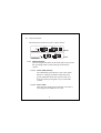
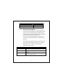
FCC Warning
This equipment has been tested and found to comply with the limits for a Class
B digital device, pursuant to Part 15 of the FCC Rules. These limitations are
designed to provide reasonable protection against harmful interference in a
residential installation. This equipment generates, uses and can radiate radio
frequency energy and, if no installed and used in accordance with the
instructions, may cause harmful interference to radio communications. However,
there is no guarantee that interference will not occur in a particular installation.
Changes or modifications to the equipment that are not approved by the party
responsible for compliance could affect the user’s authority to operate the
equipment.
CE Declaration of conformity
This equipment complies with the requirements relating to electromagnetic
compatibility, EN 55022 class B for ITE, the essential protection requirements
of Council Directive 89/336/EEC on the approximation of the laws of the
Member States relating to electromagnetic compatibility.
Trademarks:
All trade names and trademarks are the properties of their respective
companies.
Copyright © 2003, All Rights Reserved.
Document Version: 2.0
Table of Contents
1. Unpacking Information
2.
Introduction To Ethernet over VDSL Converter
2.1
2.2
2.3
2.3.1
2.3.1.1
2.3.1.2
2.3.1.3
2.3.1.4
2.3.1.5
2.3.1.6
2.3.1.7
2.3.2
2.4
2.4.1
3.
Installing And Using Ethernet over VDSL Converter
3.1
3.1.1
3.1.2
3.1.2.1
4.
General Description
Key Features
The Front Panel
LEDs definition
STATUS LED
Power LED
100M LED (Ethernet)
LINK/ACT LED (Ethernet)
FDX/COL LED (Ethernet)
LINK LED (VDSL)
ACT LED (VDSL)
MODE DIP switch
The Rear Panel
Power Connecting
Installing The Ethernet over VDSL Converter
Connect to Internet Access Concentrator
Installing Network Cables
Station Connections with Telephone Wires
Product Specifications
1
1.
Unpacking Information
Thank you for purchasing the Ethernet over VDSL converter.
Before you start, please check all the contents of this
package.
The product package should include the following:
1.
2.
3.
4.
One Ethernet over VDSL Converter
One power cord
One telephone line
User’s Manual
2
2. Introduction To Ethernet over VDSL Converter
2.1
General Description
The converter is a switching architecture with one RJ-45
10/100Mbps Ethernet port and one maximum 17Mbps
symmetric/asymmetric RJ-11 Ethernet over VDSL port
(with 2 connectors). It is ideal for signal conversion by
transmitting the Ethernet data from the standard twisted
pair cable to the telephone cable and extending the distance.
The Ethernet over VDSL combines the well proven Ethernet
and VDSL technology to transmit the Ethernet format data
by using VDSL signaling over the most widespread
telephone wires and has no impact to current voice service.
Therefore, it is very good for Internet building phoneline
network because every room or house could use the existing
phoneline to transmit data to the Internet and the whole
building could share the Internet line to the wide area
network with minimum cost.
With much enough bandwidth, the 17Mbps symmetric
capability enables many multi-media services on local
Internet come true, like VOD (Video On Demand), Internet
caching server, distance education, … and so on.
In one community or hotel, we just need to install one local
server then the multi-media services will be localized that is
3
people do not need to access the services through Internet
but using local area network with better bandwidth and
efficiency. Meanwhile, this kind of infrastructure will
minimize the burden on the Internet.
The converter is plug-n-play without any software to
configure and also fully compliant with all kinds of network
protocols. Moreover, the rich diagnostic LEDs on the
front-panel provide the operating status of individual port
and the whole system.
The cable specifications of the connection are listed as
following:
10BASE-T, Category 3, 4 or 5 UTP/STP
100BASE-TX, Category 5 UTP/STP
Ethernet over VDSL, Twisted-pair telephone wires
The drawing listed below is typical application for the
Ethernet over VDSL converter.
Master
Phone line
Slave
4
Telephone
2.2
Key Features
The converter provides the following key features:
•
Complies with IEEE802.3 10BASE-T standard
•
Complies with IEEE802.3u 100BASE-TX standard
•
Supports Ethernet over VDSL
•
5 * selective transmission modes
•
2 * RJ-11 connectors for maximum 17Mbps
symmetric/asymmetric Ethernet over VDSL port, one for
LAN connection and one for voice connection.
•
1 * 10/100Mbps Ethernet port
•
8Kbytes Ethernet transmit and 16Kbyte Ethernet receive
buffers
•
Supports extensive LED indicators for network diagnostics
•
External Linear Power
•
FCC Class B, CE
5
2.3
The Front Panel
The front panel of the converter is shown below.
Master
Slave
2.3.1
LEDs definition
The rich diagnostic LEDs on the front panel can provide
the operating status of individual port and whole
system.
2.3.1.1
Status LED (Master)
The LED blinks periodically to show the ADSL
Router is working normally. If the LED stays
green/dark that means the system is fail, you
need to contact your agent or try to reboot the
system.
2.3.1.2
Power LED
This indicator lights green when the converter is
receiving power; otherwise, it is off.
6
2.3.1.3
100M LED (Ethernet)
The RJ-45 port has a 100M LED. Steady green
indicates that the port is operating at 100Mbps. If
the LED is off, the link speed is 10Mbps.
2.3.1.4
LINK/ACT LED (Ethernet)
The RJ-45 port has a LNK/ACT LED. Steady
green (link state) indicates that the port has good
linkage to its associated device. Flashing green
indicates that the port is receiving or transmitting
data from/to its associated partner.
If the port is connected but the LNK/ACT LED is
dark, check the following items:
1. The converter and the connected device’s
power are on or not
2. The port’s cable is firmly seated in its
connectors in the switch and in the associated
device.
3. The connecting cable is good and with correct
type.
4. The connecting device, including any network
adapter is functional.
From the LED of LNK/ACT, we could judge the
connection as following:
7
LINK/ACT LED (Ethernet)
Status
Off
No Connection
Green
10/100Mbps
2.3.1.5
FDX/COL LED (Ethernet)
A collision occurs when two stations within a
collision domain attempt to transmit data at the
same time. Intermittent flashing amber of the
collision LED is normal; the contending adapters
resolve each collision by means of a
wait-then-retransmit algorithm. Frequency of
collisions is an indicator of heavy traffic on the
network.
If the FDX/COL lights amber which means the
port is under full-duplex operation or dark for
half-duplex mode. The following table is a
summary of Port LEDs.
LED (Ethernet)
100M
Operation
100Mbps (Green), 10Mbps (Off)
LINK/ACT
Link is present (Green), Activity (Blinking
Green)
Full-Duplex (Amber), Half-Duplex (Off),
COL (Blinking Amber)
FDX/COL
8
2.3.1.6
LINK LED (VDSL)
If both ends of the VDSL devices are connected
then the LED will blink for a while (in 10
seconds), this is the stage of speed
auto-negotiation. After the negotiation process,
the Link LED will stay green. If the LED blinks
always, that means the link process is fail.
2.3.1.7
ACT LED (VDSL)
If there is any traffic transverses the port then the
LED will light green. Otherwise, off means no
traffic on the network.
2.3.2
MODE DIP Switch (Master)
The converter provides 5 selective transmission modes
that defined by predetermined profiles. By switching
the transmission modes, you can obtain a best
transmission mode to suit with phone line quality or
distance of connectivity. The following is the summary
table of transmission modes, bandwidth and distance
extensibility tested for AWG 26 (0.4mm) twisted-pair
without noise and cross talk.
Profile
Name
Profile
Type
Downstream Upstream
Maximum Distance
Rate (Mbps) Rate (Mbps) between the CO
Port and the CPE
ANSI
ETSI
VE-5
VE-10
VE-15
Public
Public
Private
Private
Private
15.17
11.38
5.69
11.38
15.17
4.27
4.27
5.69
11.38
17.06
9
2900 ft
3200 ft
3600 ft
3200 ft
2900 ft
Transmission mode
ANSI
ETSI
VE-5
VE-10 (Default)
VE-15
2.4
DIP switch
ON
1
2
3
4
1
2
3
4
1
2
3
4
1
2
3
4
1
2
3
4
ON
ON
ON
ON
The Rear Panel
The rear panel of the converter is shown below
2.4.1
Power Connecting
Plug the circle end of the power adapter firmly into the
rear panel of the switch, and the other end into an
electric service outlet then the system is ready.
10
3.
Installing And Using Ethernet over VDSL Converter
3.1
Installing The Ethernet over VDSL Converter
The converter does not require any software configuration.
Users can immediately use any feature of this product
simply by attaching the cables and plug power on. There is
some key limitation on the Ethernet over VDSL networking,
please check the following items:
The device is used for point-to-point connection only and
allows data and voice work on the same telephone lines.
The two RJ-11 connectors, one for voice device connection
(like telephone) and the other one for network line
connection
Therefore, this device is an ideal client access unit for the
applications of apartment, hotel, campus and hospitality.
Integration with the Internet access Concentrator, the total
infrastructure could be a perfect solution for multi-media
local Internet. This structure could support many
multi-media applications, like VOD (Video on Demand),
Distant education, Internet caching server, … and so on.
Therefore, most of the traffic will be limited on the local
phoneline network instead of flooding to the Internet.
Another application for the converter is used for LAN to
LAN extension through the normal telephone line.
11
3.1.1
Connect to Internet Access Concentrator
In order to build up a local Internet in apartment, hotel,
campus and hospitality environment, the Internet
Access Concentrators need to be placed in the wiring
center (MDF room) and connect to the telephone line
system. On the other hand, you need to install a
converter on the individual client side and connect to
the Concentrator through the telephone lines.
When deciding where to put the converter then you
must ensure:
It is accessible and cables can be connected easily
Cabling is away from sources of electrical noise
such as radios, transmitters and power lines and
fluorescent lighting fixtures.
Water or moisture can not enter the unit
Air flow around the unit and through the vents in
the side of the case is not restricted (company
recommend that you provide a minimum of 25mm
clearance)
To prolong the operational life of your units:
Do not place objects on top of any unit or stack
Do not obstruct any vents at the sides of the case
3.1.2
Installing Network Cables
After placing the converter on the desktop, then we
need to know how to connect the device to network.
12
3.1.2.1
Station Connections with Telephone Wires
Connect the network adapters in stations to the
converter’s RJ-45 port through category 3, 4 or 5
UTP/STP cables. There are two RJ-11 phone jacks;
one for telephone set connection and the other
one is used for phoneline network connection. If
you have telephone wall jacks at home then all
you need to do is connecting the RJ-11 network
port to the wall jack through telephone wires.
13
4. Product Specifications
Standard
IEEE802.3 10BASE-T
IEEE802.3u 100BASE-TX
Ethernet over VDSL
Interface
1 * 10/100Mbps Ethernet port
2 * RJ-11 connectors for Ethernet over
VDSL and telephone set
1 * transmission modes DIP switch
Cable Connections
RJ-45: Category 3,4,5 UTP/STP
VDSL: Twisted-pair telephone wires
Network Data Rate
Ethernet: 10/100Mbps
VDSL: Maximum 17Mbps
LED indications
System
Power x1
Status x 1 (Master)
Ethernet Port
100M x1
LINK/ACTx1
FDX/COLx1
VDSL port
LINKx1
ACTx1
System Memory
8Kbyte Ethernet transmit and 16Kbyte
Ethernet receive buffers
Emission
FCC Class B, CE
Operating Temperature 00 ~ 500C
Operating Humidity
10% - 90%
Power Supply
External Linear Power
UVE7311-MS
14