1
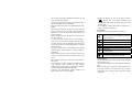
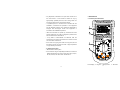
Mastech MS8268
HANDHELD DIGITAL MULTIMETER
OPERATOR’S
INSTRUCTION MANUAL
http://www.chargerbuy.com
Table of Contents
TITLE
Table of Contents
PAGE
1. GENERAL INSTRUCTIONS
1.1 Precaution safety measures
1.1.1 Preliminary
1.1.2 During use
1.1.3 Symbols
1.1.4 Instructions
1.2 Safety mechanisms
1
1
1
2
4
4
5
2. DESCRIPTION
6
2.1 Instrument Familiarization
2.2 LCD Display
2.3 Keypad
2.4 Terminals
6
7
9
10
2.5 Rotary switch
2.6 Accessories
11
11
3. FUNCTION DESCRIPTION
12
3.1 General Functions
3.1.1 Misconnection alarm system
3.1.2 DATA HOLD mode
3.1.3 Manual ranging and Autorange mode
3.1.4 Battery Saver
3.1.5 Relative measurement mode
3.2 Measurement Functions
3.2.1 AC and DC Voltage measurement
12
12
13
13
14
14
15
15
Ⅰ
PAGE
TITLE
3.2.2 Resistance measurement
16
3.2.3 Diode Test
17
3.2.4 Continuity Check
18
3.2.5 Transistor measurement
18
3.2.6 Capacitance measurement
19
3.2.7 Frequency and Duty Cycle measurement
20
3.2.8 Current measurement
22
4. TECHNICAL SPECIFICATIONS
23
4.1 GENERAL SPECIFICATIONS
4.2 Measurement specifications
4.2.1 DC Voltage
4.2.2 AC Voltage
4.2.3 Resistance
4.2.4 Audible continuity
4.2.5 Diode
4.2.6 Transistor
4.2.7 Capacitance
4.2.8 Frequency
4.2.9 DC CURRENT
4.2.10 AC CURRENT
23
24
24
25
25
25
26
26
26
26
28
28
5. MAINTENANCE
29
5.1 General Maintenance
5.2 Fuse replacement
5.3 Battery replacement
29
29
30
Ⅱ
1. GENERAL INSTRUCTIONS
This instrument complies with IEC 1010-1 (61010-1@IEC:
2001), CAT. II 1000V and CAT. III 600V overvoltage
standards. See Specifications.
To get the best service from this instrument, read carefully
this user's manual and respect the detailed safety
precautions.
International symbols used on the Meter and in this manual
are explained in chapter 1.1.3
1.1 Precautions safety measures
1.1.1 Preliminary
* Measurement category III is for measurements performed
in the building installation.
NOTE: Examples are measurements on distribution boards,
circuit-breakers, wiring, including cables, bus-bars, junction
boxes, switches, socket-outlets in the fixed installation, and
equipment for industrial use and some other equipment, for
example, stationary motors with permanent connection to
the fixed installation.
* Measurement category II is for measurements performed
on circuits directly connected to the low voltage installation.
NOTE: Examples are measurements on household
appliances, portable tools and similar equipment.
* Measurement category I is for measurements performed on
circuits not directly connected to MAINS.
NOTE: Examples are measurements on circuits not
derived from MAINS, and specially protected (internal)
MAINS derived circuits. In the latter case, transient stresses
are variable; for that reason, requires that the transient
withstand capability of the equipment is made known to the
user.
1
* When using this Multimeter, the user must observe all
normal safety rules concerning:
― Protection against the dangers of electric current.
― Protection of the Multimeter against misuse.
* For your own safety, only use the test probes supplied with
the instrument. Before use, Check that they are in good
condition.
1.1.2 During use
* If the meter is used near noise generating equipment, be
aware that display may become unstable or indicate large
errors.
* Do not use the meter or test leads if they look damaged.
* Use the meter only as specified in this manual; otherwise,
the protection provided by the meter may be impaired.
* Use extreme caution when working around bare conductors
or bus bars.
* Do not operate the meter around explosive gas, vapor, or dust.
* Verify a Meter's operation by measuring a known voltage.
Do not use the Meter if it operates abnormally. Protection
may be impaired. When in doubt, have the Meter serviced.
* Uses the proper terminals, function, and range for your
measurements.
* When the range of the value to be measured is unknown,
check that the range initially set on the multimeter is the
highest possible or, wherever possible, choose the
autoranging mode.
* To avoid damages to the instrument, do not exceed the
maximum limits of the input values shown in the technical
specification tables.
* When the multimeter is linked to measurement circuits, do
not touch unused terminals.
2
* Do not apply any voltage measurement between the 10A
terminal and the COM terminal.
* Caution when working with voltages above 60Vdc or 30Vac
rms. Such voltages pose a shock hazard.
* When using the probes, keep your fingers behind the finger
guards.
* When making connections, connect the common test lead
before connecting the live test lead; when disconnecting,
disconnect the live test lead before disconnecting the
common test lead.
* Before changing functions, disconnect the test leads from
the circuit under test.
* For all dc functions, including manual or auto-ranging, to
avoid the risk of shock due to possible improper reading,
verify the presence of any ac voltages by first using the ac
function. Then select a dc voltage range equal to or greater
than the ac range.
* Disconnect circuits power and discharge all high-voltage
capacitors before testing resistance, continuity, diodes, or
capacitance.
* Before measuring current, check the meter's fuse and turn
off power to the circuit before connecting the meter to the
circuit.
* Never perform resistance or continuity measurements on
live circuits.
* In TV repair work, or when carrying out measurements on
power switching circuits, remember that high amplitude
voltage pulses at the test points can damage the multimeter.
Use of a TV filter will attenuate any such pulses.
* Use three 1.5V AAA batteries, properly installed in the
Meter's battery case, to power the Meter.
3
* Replace the batteries as soon as the battery indicator
(
) appears. With a low battery, the Meter might
produce false readings that can lead to electric shock and
personal injury.
* Do not measure voltages above 600V in Category III, or
1000V in Category II installations.
1.1.3 Symbols:
Symbols used in this manual and on the instrument:
Caution:
refer
to
the
instruction
manual.
Incorrect use may result in damage to the device
or its components.
Dangerous voltage may be present.
~
AC (Alternating Current)
DC (Direct Current)
AC or DC
Earth ground
Double insulated
Fuse
Conforms to European Union directives
1.1.4 Instructions
* Remove test leads from the Meter before opening the Meter
case or battery cover.
* When servicing the Meter, use only specified replacement
parts.
* Before opening up the instrument, always disconnect from
all sources of electric current and make sure you are not
charged with static electricity, which may destroy internal
components.
4
* Any adjustment, maintenance or repair work carried out on
the meter while it is live should be carried out only by
2. DESCRIPTION
2.1 Instrument Familiarization
appropriately qualified personnel, after having taken into
account the instructions in this present manual.
* A "qualified person" is someone who is familiar with the
installation, construction and operation of the equipment
and the hazards involved. He is trained and authorized to
energize and de-energize circuits and equipment in
accordance with established practices.
AC
* When the instrument is opened up, remember that some
internal capacitors can retain a dangerous potential even
after the instrument is switched off.
* If any faults or abnormalities are observed, take the
instrument out of service and ensure that it cannot be used
until it has been checked out.
* If the meter is not going to be used for a long time, take out
the battery and do not store the meter in high temperature
or high humidity environment.
1.2 Safety mechanisms
* Misconnection alarm system
* If the maximum range is repeatedly exceeded, a continuous
audible signal warns the user in DCV, ACV, DCμA, ACμA,
DC mA, AC mA, DC 10A and AC 10A functions.
1. LCD display 2. Keypad
5
3. Rotary switch
6
4. Terminals
2.2 LCD Display
See Table 1 indicated for information about the LCD display.
Symbol
Table 1. Display Symbols (continued)
Meaning
RELΔ
Indicator for the Relative measurement.
Indicator for the Diode Test mode
hFE
Indicator for the transistor test mode
Indicator for the Continuity Check mode.
Indicator for the Data Hold mode
AC
V, mV
Volts. The unit of voltage.
Millivolt. 1x10⁻³ or 0.001 volts.
Meaning
A, mA, μA
The battery is low.
Warning: To avoid false readings,
which could lead to possible electric
shock or personal injury, replace the
battery as soon as the battery indicator
appears.
A: Amperes (amps). The unit of current.
mA: Milliamp. 1x10⁻³ or 0.001 amperes.
μA: Microamp. 1x10⁻⁶ or 0.000001
amperes
Ω, kΩ, MΩ
Ω:
Ohm. The unit of resistance.
kΩ: Kilohm. 1x10³ or 1000 ohms.
MΩ: Megohm. 1x10⁶ or 1,000,000 ohms.
Table 1. Display Symbols
Symbol
Indicates negative readings.
Indicator for ac voltage or current.
AC voltage and current are displayed as
the average of the absolute value of the
input, calibrated to indicate the
equivalent rms value of a sine wave.
Indicator for dc voltage or current.
AUTO
V:
mV:
The Meter is in the Autorange mode in
which the meter automatically selects
the range with the best resolution.
7
Hz:
Hz, kHz, MHz
Hertz. The unit of frequency in
cycles/second.
KHz: Kilohertz. 1x10³ or 1000 hertz.
MHz: Megahertz. 1x10⁶ or 1,000,000 hertz.
μF, nF
F: Farad. The unit of capacitance.
μF: Microfarad.1x10-6 or 0.000001 farads.
nF: Nanofarad. 1x10⁻⁹ or 0.000000001
farads.
%
%:
Percent. The unit of Duty cycle.
The input is too large for the selected
range.
8
2.3 Keypad
See Table 2 indicated for information about the keypad
operations.
Table 2. Keypad
Key
RANGE
Function
V~,V
,Ω,
mA and μA
A, mA and
μA
V~, A,
and μA.
HOLD
Any switch
Press HOLD to enter and exit
position
1. Press RANGE to enter the
manual ranging mode.
2. Press RANGE to step
through
the
ranges
available for the selected
function.
3. Press and hold RANGE for
2 seconds to return to
autoranging.
LIGHT
mA
Table 4. Terminals
Terminal
Description
Return terminal for all measurements.
COM
(Receiving the black test lead or the “com”
plug of the special multi-function socket)
Input for voltage, resistance, capacitance,
frequency,
Press REL to enter and exit
the Relative measurement
mode.
9
Press to turn the backlight on.
The backlight will be auto-off
about 5 seconds later.
See Table 4 indicated for information about the terminals.
Switches between dc and ac
current.
1 Press to start the frequency
counter.
2 Press again to enter duty
cycle (duty factor) mode.
3 Press again to exit the
frequency counter mode.
Any switch
position
the Data Hold mode.
2.4 Terminals
VΩHz
Any switch
position
Hz/ %
Operation performed
Disables automatic power-off
feature.
Power-up
Option
REL
Function
Operation performed
Switches between Diode Test
and Continuity check.
SELECT
Table 2. Keypad(continued)
Key
diode
and
continuity
measurements. (Receiving the red test lead
or the “+” plug of the special multi-function
socket).
Input for hFE and 0.001mA to 400mA
hFE μA
current measurements. (Receiving the red
mA
test lead or the “+” plug of the special
multi-function socket)
10A
Input for 400mA to 10A current
measurements. (Receiving the red test
lead).
10
2.5 Rotary switch
A eleven-position rotary selector switch gives access to
the following quantities:
¥ Current: 10A
¥ Current: mA
¥ Current: μA
¥ DC Voltage
¥ AC Voltage
¥ OFF: off position
¥ Resistance
¥ Diode and Continuity (with beep)
¥ Capacitance
¥ Transistor: hFE
¥ Frequency
3. FUNCTION DESCRIPTION
3.1 General Functions
3.1.1 Misconnection alarm system
The input terminals of the meter are equipped with sound
and light alarms against misconnection of test leads.
At V, Ω,
and
ranges:
1 The red lights at the “V” and “COM” terminals will be off
after the test leads are plugged in.
2 The buzzer will sound upon misconnection of the test
leads in the “mA” or “10A” terminals to warn the user.
At the same time, the lights at the “V” and “COM”
terminals will flash to remind the user to plug in the test
leads there.
At μA, mA, and hFE ranges:
2.6 Accessories
1 The red lights at the “mA” and “COM” terminals will be
Delivered with the multimeter:
¥ User's manual
off after the test leads are plugged in.
2 The buzzer will sound upon misconnection of the test
¥ Test leads
leads in the “V” or “10A” terminals to warn the user. At
¥ Special Multi-function socket
the same time, the red lights at the “mA” and “COM”
terminals will flash to remind the user to plug in the test
leads there.
At A range:
1 The red lights at the “10A” and “COM” terminals will be
off after the test leads are plugged in.
2 The buzzer will sound upon misconnection of the test
leads in the “V” or “mA” terminals to warn the user.
At the same time, the lights at the “10A” and “COM”
terminals will flash to remind the user to plug in the test
leads there.
11
12
3.1.2 DATA HOLD mode
Data Hold mode makes the meter stop updating the
display. Enabling Data Hold function in autorange mode
makes the meter switch to Manual ranging mode, but
the full-scale range remains the same. Data Hold
function can be cancelled by changing the measurement
mode, pressing RANGE key, or push HOLD key again.
To enter and exit the Data Hold mode:
1. Press HOLD key (short press). Fixes the display on
the current value, “H” is displayed.
2. A second short press returns the meter to normal
mode.
3.1.3 Manual ranging and Autorange mode
The Meter has both manual ranging and autorange
options.
* In the autorange mode, the Meter selects the best
range for the input detected. This allows you to switch
test points without having to reset the range.
* In the manual ranging mode, you select the range.
This allows you to override autorange and lock the
meter in a specific range.
* The Meter defaults to the autorange mode in
measurement functions that have more than one range.
When the Meter is in the autorange mode, AUTO is
displayed.
To enter and exit the manual range mode:
1. Press RANGE key. The Meter enters the manual
ranging mode. AUTO turns off. Each presses of
RANGE key increments the range. When the highest
range is reached, the Meter wraps to the lowest
range.
13
NOTE: If you manually change the measurement range
after entering the Data Hold modes, the Meter exits this
mode.
2. To exit the manual ranging mode, press and hold
down RANGE key for two seconds. The Meter
returns to the autorange mode and AUTO is
displayed.
3.1.4 Battery Saver
The Meter enters the "sleep mode" and blanks the display
if the Meter is on but not used for 15 minutes.
Press the HOLD key or rotate the rotary switch to wake
the meter up.
To disable the Sleep mode, hold down the SELECT key
while turning the meter on.
One minute before power off, the beeper will sound 5
sounds. The beeper will sound again before power off.
3.1.5 Relative measurement mode
The Meter will display relative measurement in all
functions except frequency.
To enter and exit the relative measurement mode:
1. With the Meter in the desired function, touch the test
leads to the circuit on which you want future
measurement to be based.
2. Press REL key to store the measured value and
activate the relative measurement mode. The
difference
between
the
reference
value
and
subsequent reading is displayed.
3. Press REL key for more than 2 seconds to return
the Meter to normal operation.
14