1
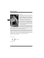
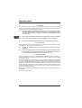
Version 1.0 October 2005 DEUTSCH COM800 MINICOM Users manual MINICOM COM800 IMPORTANT SAFETY INSTRUCTIONS CAUTION: To reduce the risk of electric shock, do not remove the top cover (or the rear section). No user serviceable parts inside; refer servicing to qualified personnel. WARNING: To reduce the risk of fire or electric shock, do not expose this appliance to rain and moisture. The apparatus shall not be exposed to dripping or splashing and no objects filled with liquids, such as vases, shall be placed on the apparatus. This symbol, wherever it appears, alerts you to the presence of uninsulated dangerous voltage inside the enclosurevoltage that may be sufficient to constitute a risk of shock. This symbol, wherever it appears, alerts you to important operating and maintenance instructions in the accompanying literature. Please read the manual. DETAILED SAFETY INSTRUCTIONS: 1) Read these instructions. 2) Keep these instructions. 3) Heed all warnings. 4) Follow all instructions. 5) Do not use this apparatus near water. 6) Clean only with dry cloth. 7) Do not block any ventilation openings. Install in accordance with the manufacturers instructions. 8) Do not install near any heat sources such as radiators, heat registers, stoves, or other apparatus (including amplifiers) that produce heat. 9) Do not defeat the safety purpose of the polarized or grounding-type plug. A polarized plug has two blades with one wider than the other. A grounding type plug has two blades and a third grounding prong. The wide blade or the third prong are provided for your safety. If the provided plug does not fit into your outlet, consult an electrician for replacement of the obsolete outlet. 10) Protect the power cord from being walked on or pinched particularly at plugs, convenience receptacles, and the point where they exit from the apparatus. 11) Only use attachments/accessories specified by the manufacturer. 12) Use only with the cart, stand, tripod, bracket, or table specified by the manufacturer, or sold with the apparatus. When a cart is used, use caution when moving the cart/apparatus combination to avoid injury from tipping over. 13) Unplug this apparatus during lightning storms or when unused for long periods of time. 14) Refer all servicing to qualified service personnel. Servicing is required when the apparatus has been damaged in any way, such as power supply cord or plug is damaged, liquid has been spilled or objects have fallen into the apparatus, the apparatus has been exposed to rain or moisture, does not operate normally, or has been dropped. 15) CAUTION - These service instructions are for use by qualified service personnel only. To reduce the risk of electric shock do not perform any servicing other than that contained in the operation instructions unless you are qualified to do so. 2 MINICOM MINICOM COM800 Ultra-Compact Stereo Modeling Compressor with 16 Presets s 16 awesome preset models for the most typical compression applications (vocal, drums, guitar, keyboard, etc.) s Dedicated Compressor Modeling control with LEDs indicating the selected dynamics program s Integrated Enhancer for brilliant, lively audio even with heavy compression s IKA (Interactive Knee Adaptation) program-adaptive compression circuitry combines the advantages of hard and soft knee characteristics s Accurate 6-digit LED Input/Output meter, plus 6-digit LED Gain Reduction meter for precise level indication s Operating levels can be selected using the I/O Level switch s High-quality potentiometers and illuminated switches for long-term reliability s Ultra low-noise audio operational amplifiers and state-of-the-art VCAs offer outstanding sound performance s All Mini Series models can be stacked on top of each other to create an ultracompact signal processor solution s High-quality components and exceptionally rugged construction ensure long life s Conceived and designed by BEHRINGER Germany 3 DEUTSCH COM800 s Ultra-compact 9.5" stereo modeling compressor for studio and stage applications MINICOM COM800 FOREWORD Dear Customer, welcome to the community of Mini Series users and thank you very much for expressing your confidence in BEHRINGER products by purchasing the COM800. It is one of my most pleasant tasks to write this letter to you, because it is the culmination of many months of hard work delivered by our engineering team to reach a very ambitious goal: to design an outstanding device whose high level of functionality will give you maximum performance. The task to design our new MINICOM certainly meant a great deal of responsibility. You, the discerning user and musician, were the focus of our entire development efforts. It also meant a lot of work and night shifts to accomplish this goal. But it was fun, too. Developing a product usually brings a lot of people together, and what a great feeling it is when everybody who participated in such a project can be proud of what weve achieved. It is our philosophy to share our joy with you, because you are the most important member of the BEHRINGER family. With your highly competent suggestions for new products youve greatly contributed to shaping our company and making it successful. In return, we guarantee you uncompromising quality as well as excellent technical and audio properties at an extremely favorable price. All of this will enable you to fully unfold your creativity without being hampered by budget constraints. We are often asked how we can make it to produce such high-grade devices at such unbelievably low prices. The answer is quite simple: its you, our customers! Many satisfied customers means large sales volumes enabling us to get better conditions of purchase for components, etc. Isnt it only fair to pass this benefit back to you? Because we know that your success is our success, too! I would like to thank all people whose help on Project MINICOM COM800 has made it all possible. Everybody has made very personal contributions, starting from the designers of the unit via the many staff members in our company to you, the user of BEHRINGER products. My friends, its been worth the trouble! Thank you very much, Uli Behringer 4 TABLE OF CONTENTS MINICOM COM800 1. INTRODUCTION .......................................................................................... 5 2. CONTROL ELEMENTS AND CONNECTIONS ........................................... 7 2.1 The front ............................................................................................................................... 7 2.2 The rear ................................................................................................................................ 8 3. THE PRESETS OF THE MINICOM ............................................................. 9 3.1 Preset categories .................................................................................................................. 9 3.2 The presets in detail .......................................................................................................... 10 4. THE MINICOM IN PRACTICE ................................................................... 11 4.1 How to set levels correctly .................................................................................................. 11 4.1.1 The I/O LEVEL switch .............................................................................................. 11 4.1.2 Signal adjustment ..................................................................................................... 11 4.2 Giving instruments more presence ................................................................................... 12 4.2.1 Using the MINICOM as a traditional compressor ................................................... 12 4.3 Giving music productions more punch .............................................................................. 12 4.3.1 Using the MINICOM as a maximizer ...................................................................... 13 5. INSTALLATION .......................................................................................... 14 5.1 Connection options and audio connections ...................................................................... 14 5.1.1 The MINICOM in the insert path ............................................................................. 14 5.1.2 The MINICOM as a mix-signal compressor connected in series ........................... 15 6. SPECIFICATIONS ...................................................................................... 16 7. OTHER MINI PRODUCTS ......................................................................... 17 8. WARRANTY ............................................................................................... 18 1. INTRODUCTION Thank you for showing your confidence in BEHRINGER products by purchasing the MINICOM COM800. The MINICOM COM800 is a preset compressor that allows you to raise both the loudness and punch of your audio material quickly and effectively. Since a lot of experience is required to be able to adjust the parameters of a compressor, the COM800 comes with 16 user-friendly presets for the most common applications to make things easier. These presets are based on tried-and-tested compressor settings and are optimized for a high level of usability. You can simply trust your ears when choosing the most appropriate setting and thus focus on what really counts: your music. Despite its ease of use the COM800 gives you all the functions of a fully-featured compressor. For example, you can use it as a mono compressor for individual signals, such as vocals, guitar, bass, etc. or as a master compressor for stereo mix signals. The downstream enhancer makes up for high-frequency loss due to high compression ratios, and the gain reduction display keeps you informed about the actual amount of compression applied. After all, you dont want to leave anything to chance. With the COM800 youll always be set for success! 1. INTRODUCTION 5 DEUTSCH 1.1 Before you get started .......................................................................................................... 6 1.1.1 Shipment .................................................................................................................... 6 1.1.2 Initial operation ........................................................................................................... 6 1.1.3 Online registration ...................................................................................................... 6 MINICOM COM800 1.1 Before you get started 1.1.1 Shipment Your COM800 was carefully packed at the assembly plant to assure secure transport. Should the condition of the cardboard box suggest that damage may have taken place, please inspect the unit immediately and look for physical indications of damage. + + + + Damaged equipment should NEVER be sent directly to us. Please inform the dealer from whom you acquired the unit immediately as well as the transportation company from which you took delivery. Otherwise, all claims for replacement/repair may be rendered invalid. Please always use the original packaging to avoid damage due to storage or shipping. Never let unsupervised children play with the COM800 or with its packaging. Please dispose of all packaging materials in an environmentally friendly fashion. 1.1.2 Initial operation Be sure that there is enough space around the unit for cooling. To avoid overheating, do not place the COM800 on top of power amps or near radiators, etc. + + To power the COM800, use only the power supply unit that is delivered with your equipment. Please ensure that the unit is installed and operated only by people qualified to do so. During installation and operation the user must have sufficient electrical contact to earth. Electrostatic discharge may affect the operation of the unit. 1.1.3 Online registration Please do remember to register your new BEHRINGER equipment right after your purchase by visiting www.behringer.com (alternatively www.behringer.de) and kindly read the terms and conditions of our warranty carefully. Should your BEHRINGER product malfunction, our goal is to have it repaired as quickly as possible. To arrange for warranty service, please contact the retailer from whom the equipment was purchased. Should your BEHRINGER dealer not be located in your vicinity, you may directly contact one of our subsidiaries. Corresponding contact information is included in the original equipment packaging (Global Contact Information/European Contact Information). Should your country not be listed, please contact the distributor nearest you. A list of distributors can be found in the support area of our website (www.behringer.com/support). Registering your purchase and equipment with us helps us process your repair claims quicker and more efficiently. Thank you for your cooperation! 6 1. INTRODUCTION MINICOM COM800 2. CONTROL ELEMENTS AND CONNECTIONS DEUTSCH 2.1 The front Fig. 2.1: Front panel control elements of the COM800 + The two LED displays show the preset currently selected. One LED is assigned to each preset. The LED of the active preset lights up. The presets are grouped in six different categories (see chapter 3.1). Use the PRESETS control to select one of the 16 different effect presets. Use the INPUT LEVEL control to adjust the input signal level. This determines to a great extent how much compression is applied. If the level is too low, it may happen that the compressor does not work, irrespective of the preset selected. Therefore, a sufficiently high input level should be chosen, as described in chapter 4.1. The ENHANCER button activates a compensation circuit which boosts the treble range and thus makes up for any high-frequency loss that may result from high compression ratios. Use the OUTPUT LEVEL control to raise the loudness of the mix signal and benefit from the dynamic range achieved by compression. Use the METER button to choose whether the LED display shows the INPUT or OUTPUT signals. Always monitor the output level when raising it with the OUTPUT LEVEL control . The IN/OUT button enables/disables the signal processing circuitry of the COM800. The COM800 works only when this button is lit. If it does not show, the input signal is routed directly to the output without any processing. The GAIN RED LEDs display the amount by which the signal level is reduced due to the compression process. The display reads from top to bottom, i.e. the lowest amount of reduction is shown by the top LED, while all the LEDs down to the bottom LED light up when maximum gain reduction is applied. The LED display allows you to monitor the input and output levels. It comprises 6 LEDs. Use the highest input/output levels possible, so that the compressor works most effectively. When the CLIP LED lights up, this indicates that distortion may occur within the circuitry of the COM800. In this case, the signal level must be reduced. The switch turns your MINICOM COM800 on and off. The switch lights up when the unit is switched on. 2. CONTROL ELEMENTS AND CONNECTIONS 7 MINICOM COM800 + Merely switching the unit off does not mean that it is fully disconnected from the mains. To disconnect the unit from the mains, pull out the mains connector. Please make sure before installation that the mains connector has not been damaged. If you do not use the unit for an extended period of time, please disconnect it at the mains. 2.2 The rear Fig. 2.2: Rear panel connectors of the COM800 The COM800 is connected to the mains using a 2-pole POWER connector jack. A matching mains adaptor is included with the unit. + Always use the mains adaptor supplied with the unit to avoid damage to your COM800. The two OUTPUT connectors are on 1/4" jacks and provide an unbalanced left/right signal. When you select a mono preset, both jacks will provide the same mono signal. The I/O LEVEL switch determines the level used by the signal processing circuitry of the COM800: -10 dBV (home recording level) or +4 dBu (studio level). + Make sure to set the correct reference level that matches the operating level used by other equipment connected. Otherwise, distortion may be caused and your COM800 will not function optimally (see chapter 4.1). The two INPUT connectors are on 1/4" jacks. Always use balanced patch cords with 1/4" plugs or standard insert cables (unbalanced connection). Mono signals should be connected to the L jack. SERIAL NUMBER. 8 2. CONTROL ELEMENTS AND CONNECTIONS MINICOM COM800 3. THE PRESETS OF THE MINICOM The COM800 comes with a total of 16 different presets. These pre-programmed compressor settings save you a lot of work and trouble. Depending on the application in question they give you the desired results. You dont have to be familiar with the complex parameters of a compressor for your music to benefit from the use of the COM800. + When using a mono preset only one mono signal can be processed with the COM800. In this case please use the INPUT jack L (MONO) . It is not possible to process two mono signals independently of each other! 3.1 Preset categories The COM800 features presets for compressing individual signals (e.g. guitar, drums, etc.) or stereo/ mix signals (e.g. keyboard, main mix, sub-groups). To give you a better overview, the presets are grouped in six categories based on typical applications. &DWHJRU\ Vocals (presets 1-3) $SSOLFDWLRQ Optimized settings for vocal parts with lots of punch and presence using different degrees of compression. Drums + percussion Special presets with optimized control times (presets 4-5) for powerful percussion sounds. Guitars (presets 6-8) Adapted control behavior for powerful electric and punchy acoustic guitars. Keyboards (presets 9-11) Maximized sound density for electronic keyboard sounds and piano. Mastering presets ensuring effective loudness maximization and level limiting for “mighty mixes”. Limiter (presets 12-13) All-round/special (presets 14-16) 6LJQDOW\SH Presets for special applications. Individual signals Individual/stereo signals Individual signals Stereo signals Mix signals Individual/mix signals Table 3.1: The preset categories of the MINICOM 3. THE PRESETS OF THE MINICOM 9 DEUTSCH Some presets are designed for stereo signals, some can be used for mono signals only. Depending on the preset chosen you can use your COM800 to process single or mix signals. MINICOM COM800 3.2 The presets in detail The 16 presets of the MINICOM have been optimized for a variety of applications. Feel free to use them for other purposes too. In the end, only the sound achieved determines whether or not a preset is the right one for the desired result. &DWHJRU\ 1R 1 Vocals 2 3 Drums + percussion 4 5 6 Guitars 7 8 9 Keyboards 10 11 Limiter 12 13 14 All-round/ special 3UHVHW Powerful compression, which gives electric basses presence in the E-BASS lower frequency range that you can actually feel. Increases the presence of the signal and makes the characteristic ACOUST plucking sounds of acoustic guitars audible, so that they don’t get GUIT drowned out in the mix. Produces the hard-edge sound of distorted electric guitars with E-GUITAR constant presence. Limits the enormous dynamics of the piano for a more consistent GRAND sound, which better integrates into the mix and has more punch. PIANO FAT SYNTH Fat sound for aggressive “forefront” synth sounds. KEYB PAD HARD LIMIT SOFT LIMIT PRESSURE PUMP UP 15 LEVELER 16 (IIHFW Moderate compression with sufficient dynamics for optimum integration of vocals in the mix. Ideal for ballads. Medium compression which brings the vocals in the mix to the VOC foreground, but leaves enough room for vocal dynamics. Ideal for MEDIUM hip-hop and pop. Strong compression for a very present vocal sound without any VOC POWER compromise. Ideal for dance, hard rock and heavy metal. Fat sound for bass and snare drum, which retains the high-energy FAT DRUMS attack phase of the instrument. PERCUSS. Dense and present sound for drums/percussion. VOCAL SOFT Reduces the dynamic range of keyboard pad sounds, which can make a mix rather muddy with their excessive dynamic range. The ultimate loudness raiser for aggressive and high-energy productions. Ideal for dance, pop and rock. Produces a round, consistent and fat mastering sound. Ideal for hiphop, chill out and trance. All-round preset for more punch and loudness. Ideal for important solo instruments. Compression with audible control processes, which is desired in this case and produces trendy “pumping” effects. Ideal for drum sounds. Keeps the level constant without limiting level peaks. Ideal to adapt tracks with different loudness to each other, e.g. for CD compilations. Table 3.2: MINICOM presets and ideal areas of application 10 3. THE PRESETS OF THE MINICOM 7\SH Mono Mono Mono Mono Stereo Mono Mono Mono Stereo Stereo Stereo Stereo Stereo Mono/ Stereo Mono/ Stereo Mono/ Stereo Typically, music production comprises three steps: the actual recording as well as the mix and mastering processes. First of all, individual signals are recorded. In a computer-based production environment this means that each instrument is recorded on a different track. When using software sound generators, the individual signals are directly available from the computer. Mixing means that the volume levels of the instruments are adjusted, effects are added were needed and the frequency range of each instrument is optimized with equalizers. During the mastering process equalizers and control amplifiers are used to give the mix the finishing touch, so as to achieve a homogeneous sound and optimum loudness. Compressors have become the standard tool for dynamics processing during all stages of a production. Today, these popular control amplifiers are widely used for music production. Traditionally, compressors are used to limit the dynamic range of a signal, i.e. to reduce the difference between the highest and the lowest signal levels. This is useful, in particular, to control volume fluctuations in instrument signals during the mixing process. In addition, compression can also be used to enhance the sound of a production. 4.1 How to set levels correctly 4.1.1 The I/O LEVEL switch Before you can give your signals additional punch and power, please make sure to set the levels of your MINICOM correctly. First of all, adjust the proper operating level using the I/O LEVEL switch on the rear panel of the unit. -10 dBV are used in a consumer environment, +4 dBu in professional recording studios. Many semi-professional audio cards and studio devices can be set accordingly by means of a hardware/software switch. Mixing consoles usually work with the professional 4 dBu level, while guitars, basses, keyboards and consumer equipment (CD/MD-DAT players/recorders) use -10 dBV. If you are not sure which level to use, please consult the users manuals of your devices or simply try which setting gives you a reasonable level on the IN/OUT LED display . Always make sure that the INPUT LEVEL control is set to zero and the METER switch to INPUT. + If you can select the operating level used by your studio equipment, please be sure to have the same level used by all devices. 4.1.2 Signal adjustment Wire the MINICOM as described in chapter 5.1, depending on the application. Now, apply the signal to be compressed and use the METER switch to set the IN/OUT LED display to INPUT, so that it shows the input level. Turn the INPUT LEVEL control , until the signal level displayed is around the 0 dB marking between -6 dB and +6 dB and the CLIP LED does not light up. Select the preset of your choice and activate the compressor in the signal path with the IN/OUT button . The GAIN RED LEDs display the gain reduction produced by the compression process. Check the output signal by setting the IN/OUT LED display to OUTPUT using the METER switch , and raise the level until the signal is around the 0 dB marking between -6 dB and +6 dB. Since the GAIN RED LEDs show the gain reduction achieved by compression, they give you an indication of the level by which the signal can be raised with the OUTPUT LEVEL control . 4. THE MINICOM IN PRACTICE 11 DEUTSCH MINICOM COM800 4. THE MINICOM IN PRACTICE MINICOM COM800 4.2 Giving instruments more presence Compressors are most often used to optimize the levels of individual signals during recording or mixing. When doing a mix you have surely noticed at some point or other that it is difficult to control the volume of some signals. Lets take vocals as an example: When all settings are ok for the verse, you can be sure that the vocals are too loud in the chorus, because the singer suddenly turns up the volume. Additionally, even language-based differences in volume and changing distances between singer and microphone can lead to passages getting drowned in the mix. A compressor is the ideal solution to this typical problem: it limits the dynamic range and produces are more consistent signal which integrates better into the mix. In particular, very dynamic, non-percussive acoustic instruments such as acoustic guitar, vocals, etc. benefit from compression when you need to make them audible alongside very dominant sounds and get more control over their dynamic behavior. In addition to the more basic task of limiting the dynamic range, extreme compressor settings can produce interesting sound changes. This effect is most often used for drum sounds, but interesting results can be achieved with other signals, too. This can range from making the instrument-specific decay phases of percussive instruments clearly heard (drums, acoustic guitars, piano, etc.) to attenuating the attack phase. Through the consistent use of compressors for individual signals during the mix, the overall mix gets denser and can be processed more effectively during the subsequent mastering process. But you should always keep in mind that compression does not necessarily benefit your music production. Therefore, the results should always be evaluated critically and played to the unbiased ears of other people. 4.2.1 Using the MINICOM as a traditional compressor If you have a mixing console you can connect the MINICOM to the insert path of the single channels whose signal you wish to compress. To process an entire group of instruments you could also use a sub-group insert. If your mixing console has no inserts, you can connect the MINICOM directly between signal source and mixing console for line-level signals (see chapters 5.1.1 and 5.1.2). The following settings are made on the device: s Depending on the signal, select a suitable preset and adjust the input/output levels as described in chapter 4.1.2. ). s If the compressed signal lacks brilliance, you can activate the enhancer circuit (button s Use the IN/OUT button to keep comparing the compressed signal with the original signal. This is to ensure that the quality of your production benefits from the dynamic processing and does not tend to sound cluttered due to incorrect settings. If the signal is too flat and lacks life, you can try to reduce the input level slightly with the INPUT LEVEL control , or select another preset. 4.3 Giving music productions more punch Todays music productions need one thing in particular: maximum loudness, or volume. Productions with a broad dynamic range usually sound thin and lack the necessary punch, especially when its dance or pop music. In contrast to mastered tracks with high loudness, such productions have a poor and inhomogeneous sound due to volume differences. Since audio devices and recording/playback media have a limited dynamic range, signals can be recorded with limited loudness only, which is predetermined by the technically feasible level of the medium (CD, DAT, TAPE, etc.). 12 4. THE MINICOM IN PRACTICE MINICOM COM800 DEUTSCH These limits must be exploited fully to achieve maximum volume in a production. However, uncompressed signals have a great number of transient signal peaks, which can be significantly louder than the average signal level. These signal peaks represent the maximum limit to which the level can be raised. Since these are signal peaks, the dynamic range is used only briefly. The average signal level actually perceived by the listener, however, is far below these signal peaks. The following figure illustrates this relationship. Fig. 4.1: Waveform view of the compression process Compressors can minimize signal peaks, i.e. can reduce them in volume. Thus, previously unused dynamic range is available which gives you some scope to raise the loudness level of your production. Your music becomes denser and its loudness is effectively raised. In mastering terminology this process is known as maximizing. The term limiting refers to the necessary compressor settings. So, a limiter is a particularly effective compressor. 4.3.1 Using the MINICOM as a maximizer If you have a mixing console you can connect the MINICOM to the insert paths of the main-mix bus or a sub-group insert. In the latter configuration, you have to route your mix to the corresponding sub-group (see chapter 5.1.1). If your work is completely computer-based or if your mixing console has no inserts on the main-mix bus, you can also connect the MINICOM directly to the outputs of your audio card/mixing console (see chapter 5.1.2). The following settings are made on the device: s Select the preset HARD LIMIT (12), SOFT LIMIT (13) or PRESSURE (14) and adjust the input/output levels as described in chapter 4.1.2. s Activate the enhancer circuit (button the limiting process. s Use the IN/OUT button to keep comparing the compressed signal with the original signal. This is to ensure that the quality of your production benefits from the dynamic processing and does not tend to sound cluttered due to incorrect settings. If the signal is too flat and lacks life, you can try to reduce the input level slightly with the INPUT LEVEL control , or select another preset. ) to make up for the high-frequency loss caused by 4. THE MINICOM IN PRACTICE 13 MINICOM COM800 5. INSTALLATION 5.1 Connection options and audio connections There are various ways to integrate the COM800 into your set-up. Depending on the application in question, you will need different sets of connecting cables. 5.1.1 The MINICOM in the insert path Connect the MINICOM via the insert paths of a mixing console if you want to compress individual signals or sub-groups comprising several instruments. Use standard insert cables. These Y cables have two 1/4" TS connectors at one end, and one 1/4 TRS connector at the other. Connect the plug marked Send to the INPUT L jack of the COM800. Connect the Return plug to the corresponding OUTPUT L jack of the device. Connect the TRS connector to the insert jack of the channel strip on the mixing console. For sub-group stereo compression use two insert cables and select a suitable preset. The second cable must be connected to the INPUT/OUTPUT R jacks of the COM800. Fig. 5.1: Connecting the MINICOM to the insert paths Fig. 5.2: Insert cable with one 1/4" TRS and two 1/4" TS connectors 14 5. INSTALLATION MINICOM COM800 5.1.2 The MINICOM as a mix-signal compressor connected in series DEUTSCH If your mixing console has no insert connectors, you can also connect the MINICOM to the outputs of an audio card or the main-mix outputs of a mixing console. In this configuration the outputs of the mixing console/audio card are connected to the inputs of the MINICOM. Then, connect the outputs of the COM800 directly to the recording device or the inputs of the audio card. The following illustration shows the corresponding wiring scheme. Fig. 5.3: Wiring example: the MINICOM as a main-mix compressor connected in series Use standard cables with two 1/4" connectors, sometimes also referred to as patch cords or instrument cables. Fig. 5.4: Unbalanced cable with 1/4" TS connectors If your equipment has balanced outputs, you can also use balanced cables to connect the inputs of the COM800. Balanced cables are immune to interference, such as hum caused by power cords. If you want to operate your MINICOM in mono only, connect one cable each to the left input and output jacks. Select a suitable mono preset. 5. INSTALLATION 15 MINICOM COM800 Fig. 5.5: Balanced cable with 1/4" TRS connectors 6. SPECIFICATIONS INPUT Connectors Input impedance Nominal operating level Max. input level OUTPUT Connectors Output impedance Max. output level COMPRESSOR SECTION Compression ratio Input gain Output gain ENHANCER SECTION Type Frequency Max. boost SYSTEM DATA Frequency response Dynamic range THD Signal crosstalk Signal-to-noise ratio POWER SUPPLY Mains connection Mains voltages USA/Canada U.K./Australia China Europe Japan Power consumption DIMENSIONS/WEIGHT Dimensions (H x W x D) Weight 1/4" stereo jack, balanced approx. 10 kW unbalanced, approx. 20 kW balanced -10 dBV /+4 dBu (switchable) 15 dBu at +4 dBu nom. level 1/4" jack, unbalanced approx. 150 W 15 dBu 1.1 : 1 to 7.1 : 1 (depending on preset) -20 dB to 20 dB -20 dB to 20 dB Dynamic high-pass filter (6 dB/oct.) 5 kHz approx. +12 dB @ 5 kHz 10 Hz to 200 kHz, ±1.5 dB 95 dB, 20 Hz to 20 kHz 0.12 % typ. @ 0 dBu -75 dB @ 1 kHz 97 dB @ +4 dBu, A-weighted external mains adaptor, 9 V~, 750 mA 120 V~, 60 Hz 240 V~, 50 Hz 220 V~, 50 Hz 230 V~, 50 Hz 100 V~, 50 - 60 Hz approx. 6 W approx. 1 8/9" x 9 5/9" x 4 5/7" (approx. 48 mm x 242.6 mm x 120 mm) approx. 0.84 lbs. (approx. 0.380 kg) BEHRINGER is constantly striving to maintain the highest professional standards. As a result of these efforts, modifications may be made from time to time to existing products without prior notice. Specifications and appearance may differ from those listed or illustrated. 16 6. SPECIFICATIONS MINICOM COM800 7. OTHER MINI PRODUCTS The MINICOM belongs to the MINI suite of BEHRINGER products, which can operate together and are introduced below: MINIFEX FEX800 DEUTSCH Ultra-compact 9.5" stereo multi-effects processor for studio and stage applications s 16 awesome FX presets in 24-bit/48 kHz resolution including reverb, delay, chorus, flanger, phaser, rotary speaker, pitch shifter and multi-effects s Intuitive FX Preset control with LEDs indicating the selected program MINIAMP AMP800 Ultra-compact 9.5" headphones amplifier system for studio and stage applications s s 4 totally independent stereo high-power amplifier sections Highest sonic quality with virtually all types of headphones even at maximum volume MINIMIC MIC800 Ultra-compact 9.5" microphone modeling preamp for studio and stage applications s High-end preamplifier for all microphone, instrument and line-level sources. Perfectly complements studio-grade condenser mics s Ultra-flexible Preamp Modeling allows you to quickly optimize your recordings MINIMON MON800 Ultra-compact 9.5" monitor matrix mixer for studio and stage applications s Dedicated input section with 4 selectable and mixable stereo inputs s Accurate 6-digit LED main stereo output meters for precise level indication MINIBEAT BEAT800 Ultra-compact 9.5" dual beat counter/phono preamp for studio and stage applications s Intelligent dual BPM counters with Tempo Difference indicator s Ultra-flexible Beat Assist and Sync Lock functions MINIFBQ FBQ800 Ultra-compact 9.5" graphic equalizer for studio and stage applications s Revolutionary FBQ Feedback Detection System instantly reveals critical frequencies and can also be used as Audio Analyzer s Additional Low Cut filter removes unwanted frequencies, e. g. floor rumble MINIMIX MIX800 Ultra-compact 9.5" karaoke machine for studio and stage applications s Revolutionary Voice Cancellereffectively eliminates vocals from any stereo source while retaining most music elements s Integrated digital echo/reverb processor in 24bit/40 kHz resolution for ultimate vocal enhancement Fig. 7.1: MINI products stack on top of each other 7. OTHER MINI PRODUCTS 17 MINICOM COM800 8. WARRANTY § 1 OTHER WARRANTY RIGHTS AND NATIONAL LAW 1. This warranty does not exclude or limit the buyers statutory rights provided by national law, in particular, any such rights against the seller that arise from a legally effective purchase contract. 2. The warranty regulations mentioned herein are applicable unless they constitute an infringement of national warranty law. § 2 ONLINE REGISTRATION Please do remember to register your new BEHRINGER equipment right after your purchase by visiting www.behringer.com (alternatively www.behringer.de) and kindly read the terms and conditions of our warranty carefully. Registering your purchase and equipment with us helps us process your repair claims quicker and more efficiently. Thank you for your cooperation! § 3 WARRANTY 1. BEHRINGER (BEHRINGER International GmbH including all BEHRINGER subsidiaries listed on the enclosed page, except BEHRINGER Japan) warrants the mechanical and electronic components of this product to be free of defects in material and workmanship for a period of one (1) year* from the original date of purchase, in accordance with the warranty regulations described below. If the product shows any defects within the specified warranty period that are not excluded from this warranty as described under § 5, BEHRINGER shall, at its discretion, either replace or repair the product using suitable new or reconditioned parts. In the case that other parts are used which constitute an improvement, BEHRINGER may, at its discretion, charge the customer for the additional cost of these parts. 2. If the warranty claim proves to be justified, the product will be returned to the user freight prepaid. 3. Warranty claims other than those indicated above are expressly excluded. § 4 RETURN AUTHORIZATION NUMBER 1. To obtain warranty service, the buyer (or his authorized dealer) must call BEHRINGER (see enclosed list) during normal business hours BEFORE returning the product. All inquiries must be accompanied by a description of the problem. BEHRINGER will then issue a return authorization number. 2. Subsequently, the product must be returned in its original shipping carton, together with the return authorization number to the address indicated by BEHRINGER. 3. Shipments without freight prepaid will not be accepted. § 5 WARRANTY REGULATIONS 1. Warranty services will be furnished only if the product is accompanied by a copy of the original retail dealers invoice. Any product deemed eligible for repair or replacement under the terms of this warranty will be repaired or replaced. 2. If the product needs to be modified or adapted in order to comply with applicable technical or safety standards on a national or local level, in any country which is not the country for which the product was originally developed and manufactured, this modification/adaptation shall not be considered a defect in materials or workmanship. The warranty does not cover any such modification/ adaptation, irrespective of whether it was carried out properly or not. Under the terms of this warranty, BEHRINGER shall not be held responsible for any cost resulting from such a modification/adaptation. 3. Free inspections and maintenance/repair work are expressly excluded from this warranty, in particular, if caused by improper handling of the product by the user. This also applies to defects caused by normal wear and tear, in particular, of faders, crossfaders, potentiometers, keys/buttons, tubes, guitar strings, illuminants and similar parts. 18 8. WARRANTY MINICOM COM800 s improper handling, neglect or failure to operate the unit in compliance with the instructions given in BEHRINGER user or service manuals. s connection or operation of the unit in any way that does not comply with the technical or safety regulations applicable in the country where the product is used. s damages/defects caused by force majeure or any other condition that is beyond the control of BEHRINGER. 5. Any repair or opening of the unit carried out by unauthorized personnel (user included) will void the warranty. 6. If an inspection of the product by BEHRINGER shows that the defect in question is not covered by the warranty, the inspection costs are payable by the customer. 7. Products which do not meet the terms of this warranty will be repaired exclusively at the buyers expense. BEHRINGER will inform the buyer of any such circumstance. If the buyer fails to submit a written repair order within 6 weeks after notification, BEHRINGER will return the unit C.O.D. with a separate invoice for freight and packing. Such costs will also be invoiced separately when the buyer has sent in a written repair order. § 6 WARRANTY TRANSFERABILITY This warranty is extended exclusively to the original buyer (customer of retail dealer) and is not transferable to anyone who may subsequently purchase this product. No other person (retail dealer, etc.) shall be entitled to give any warranty promise on behalf of BEHRINGER. § 7 CLAIM FOR DAMAGES Failure of BEHRINGER to provide proper warranty service shall not entitle the buyer to claim (consequential) damages. In no event shall the liability of BEHRINGER exceed the invoiced value of the product. * Customers in the European Union please contact BEHRINGER Germany Support for further details. Technical specifications and appearance subject to change without notice. The information contained herein is correct at the time of printing. The names of companies, institutions or publications pictured or mentioned and their respective logos are registered trademarks of their respective owners. Their use neither constitutes a claim of the trademarks by BEHRINGER® nor affiliation of the trademark owners with BEHRINGER®. BEHRINGER® accepts no liability for any loss which may be suffered by any person who relies either wholly or in part upon any description, photograph or statement contained herein. Colours and specification may vary slightly from product. Products are sold through our authorised dealers only. Distributors and dealers are not agents of BEHRINGER® and have absolutely no authority to bind BEHRINGER® by any express or implied undertaking or representation. No part of this manual may be reproduced or transmitted in any form or by any means, electronic or mechanical, including photocopying and recording of any kind, for any purpose, without the express written permission of BEHRINGER Spezielle Studiotechnik GmbH. BEHRINGER® is a registered trademark. ALL RIGHTS RESERVED. © 2005 BEHRINGER Spezielle Studiotechnik GmbH, Hanns-Martin-Schleyer-Str. 36-38, 47877 Willich-Münchheide II, Germany. Tel. +49 2154 9206 0, Fax +49 2154 9206 4903 8. WARRANTY 19 DEUTSCH 4. Damages/defects caused by the following conditions are not covered by this warranty: