1
SPECIAL MESSAGE SECTION
PRODUCT SAFETY MARKINGS: Yamaha electronic products may have either labels similar to the graphics shown
below or molded / stamped facsimiles of these graphics on
the enclosure. The explanation of these graphics appears on
this page.
Please observe all cautions indicated on this page and those
indicated in the safety instruction section.
CAUTION
RISK OF ELECTRIC SHOCK.
DO NOT OPEN
CAUTION: TO REDUCE THE RISK OF
ELECTRIC SHOCK, DO NOT REMOVE
COVER (OR BACK). NO USER-SERVICEABLE
PARTS INSIDE. REFER SERVICING TO
QUALIFIED SERVICE PERSONNEL.
See the name plate for graphic symbol markings.
The exclamation point within the
equilateral triangle is intended to alert
the user to the present of important
operating
and
maintenance
(servicing) instructions in the
literature accompanying the product.
The lightning flash with arrowhead
symbol within the equilateral triangle
is intended to alert the user to the
presence of uninsulated "dangerous
voltage" within the product's
enclosure that may be of sufficient
magnitude to constitute a risk of
electrical shock.
ENVIRONMENTAL ISSUES: Yamaha strives to produce
products that are both user safe and environmentally
friendly.
We sincerely believe that our products and the production
methods used to produce them, meet these goals. In
keeping with both the letter and the spirit of the law, we want
you to be aware of the following:
BATTERY NOTICE: This product MAY contain a small
nonrechargeable battery which (if applicable) is soldered in
place. The average life span of this type of battery is
approximately five years. When replacement becomes
necessary, contact a qualified service representative to
perform the replacement.
WARNING: Do not attempt to recharge, disassemble, or
incinerate this type of battery. Keep all batteries away from
children. Dispose of used batteries promptly and as
regulated by applicable laws. Note: In some areas, the
servicer is required by law to return the defective parts.
However, you do have the option of having the servicer
dispose of these parts for you.
DISPOSAL NOTICE: Should this product become
damaged beyond repair, or for some reason its useful life is
considered to be at an end, please observe all local, state,
and federal regulations that relate to the disposal of
products that contain lead, batteries, plastics, etc.
NOTICE: Service charges incurred due to lack of knowledge
relating to how a function or effect works (when the unit is
operating as designed) are not covered by the
manufacture's warranty, and are therefore the owner's
responsibility.
Please study this manual carefully and consult your dealer
before requesting service.
NAME PLATE LOCATION: The graphic below indicates the
location of the name plate. The model number, serial
number, power requirements, etc., are located on this plate.
You should record the model number, serial number, and
the date of purchase in the spaces provided below and
retain this manual as a permanent record of your purchase.
IMPORTANT NOTICE: All Yamaha electronic products are
tested and approved by an independent safety testing
laboratory in order that you may be sure that when it is
properly installed and used in its normal and customary
manner, all foreseeable risks have been eliminated. DO NOT
modify this unit or commission others to do so unless
specifically authorized by Yamaha.
Product performance and/or safety standards may be
diminished. Claims filed under the expressed warranty may
be denied if the unit is/has been modified. Implied warranties
may also be affected.
SPECIFICATIONS SUBJECT TO CHANGE: The information
contained in this manual is believed to be correct at the time
of printing. However, Yamaha reserves the right to change or
modify any of the specifications without notice or obligation
to update existing units.
92-469-➀
CAUTION
RISK OF ELECTRIC SHOCK
DO NOT OPEN
ATTENTION:RISQUE DE CHOC ELECTRIQUE NE PAS OUVRIR.
WARNIING
MODEL
SER.NO.
TO REDUCE THE RISK OF FIRE OR ELECTRIC
SHOCK. DO NOT EXPOSE THIS PRODUCT TO RAIN OR MOISTURE.
THIS DEVICE COMPLIES WITH PART 15 OF THE FCC RULES. OPERATION IS
SUBJECT TO THE FOLLOWING TWO CONDITIONS:
(1)THIS DEVICE MAY NOT CAUSE HARMFUL INTERFERENCE, AND (2)THIS DEVICE
POWER
MUST ACCEPT ANY INTERFERENCE RECEIVED, INCLUDING INTERFERENCE THAT
ON/ OFF
MAY CAUSE UNDESIRED OPERATION.
Model
Serial No.
Purchase Date
AC INLET
IMPORTANT SAFETY INSTRUCTIONS
INFORMATION RELATING TO PERSONAL INJURY, ELECTRICAL SHOCK,
AND FIRE HAZARD POSSIBILITIES HAS BEEN INCLUDED IN THIS LIST.
WARNING- When using any electrical or electronic product,
basic precautions should always be followed. These
precautions include, but are not limited to, the following:
1.
Read all Safety Instructions, Installation Instructions,
Special Message Section items, and any Assembly
Instructions found in this manual BEFORE making any
connections, including connection to the main supply.
8.
This product was NOT designed for use in wet/damp
locations and should not be used near water or exposed to
rain. Examples of wet /damp locations are; near a swimming
pool, spa, tub, sink, or wet basement.
9.
2. Do not attempt to service this product beyond that
This product should be used only with the components
supplied or; a cart ,rack, or stand that is recommended by
the manufacturer . If a cart, rack, or stand is used, please
observe all safety markings and instructions that
accompany the accessory product.
described in the user-maintenance instructions. All other
servicing should be referred to qualified service personnel.
10.
3.
Main Power Supply Verification: Yamaha products are
manufactured specifically for the supply voltage in the area
where they are to be sold. If you should move, or if any doubt
exists about the supply voltage in your area, please contact
your dealer for supply voltage verification and (if applicable)
instructions.The required supply voltage is printed on the
name plate. For name plate location, please refer to the
graphic found in the Special Message Section of this manual.
4. DANGER-Grounding Instructions: This product must be
grounded and therefore has been equipped with a three pin
attachment plug. If this product should malfunction, the
ground pin provides a path of low resistance for electrical
current, reducing the risk of electrical shock. If your wall
socket will not accommodate this type plug, contact an
electrician to have the outlet replaced in accordance with
local electrical codes. Do NOT modify the plug or change the
plug to a different type!
5. WARNING: Do not place this product or any other
objects on the power cord or place it in a position where
anyone could walk on, trip over, or roll anything over power
or connecting cords of any kind. The use of an extension
cord is not recommended! If you must use an extension
cord, the minimum wire size for a 25' cord (or less) is 18
AWG. NOTE: The smaller the AWG number, the larger the
current handling capacity. For longer extension cords,
consult a local electrician.
6. Ventilation: Electronic products, unless specifically
designed for enclosed installations, should be placed in
locations that do not interfere with proper ventilation. If
instructions for enclosed installation are not provided, it must
be assumed that unobstructed ventilation is required.
7.
Temperature considerations: Electronic products
should be installed in locations that do not seriously
contribute to their operating temperature. Placement of this
product close to heat sources such as; radiators, heat
registers etc., should be avoided.
The power supply cord (plug) should be
disconnected from the outlet when electronic products are to
be left unused for extended periods of time. Cords should
also be disconnected when there is a high probability of
lightning and/or electrical storm activity.
11. Care should be taken that objects do not fall on and
liquids are not spilled into the enclosure through any
openings that may exist.
12. Electrical/electronic products should be serviced by
a qualified service person when:
a. The power supply cord has been damaged; or
b. Objects have fallen, been inserted, or liquids have
been spilled into the enclosure through openings; or
c. The product has been exposed to rain; or
d. The product does not operate, exhibits a marked
change in performance; or
e. The product has been dropped, or the enclosure of
the product has been damaged.
13. This product, either alone or in combination with an
amplifier and headphones or speaker/s, may be capable of
producing sound levels that could cause permanent hearing
loss. Do NOT operate for a long period of time at a high
volume level or at a level that is uncomfortable. If you
experience any hearing loss or ringing in the ears, you
should consult an audiologist.
IMPORTANT: The louder the sound, the shorter the time
period before damage occurs.
14. Some Yamaha products may have benches and / or
accessory mounting fixtures that are either supplied as a part
of the product or as optional accessories. Some of these
items are designed to be dealer assembled or installed.
Please make sure that benches are stable and any optional
fixtures (where applicable) are well secured BEFORE using.
Benches supplied by Yamaha are designed for seating only.
No other uses are recommended.
PLEASE KEEP THIS MANUAL
92-469-3
CONTENTS
BEFORE YOU BEGIN ....................................................7
FRONT PANEL .......................................................10
REAR PANEL .........................................................15
SYSTEM LOGIC ......................................................17
GETTING STARTED ...................................................43
SETUP & PLAY ......................................................44
LOADING & PLAYING THE DEMO ...........................52
PROGRAMMING ....................................................56
SAVING & LOADING .............................................64
INTEGRATING INTO A MIDI SYSTEM ......................67
■ FEATURE REFERENCE................71
SONG MODE .................................................................72
SONG PLAY ...........................................................73
SONG MULTI ......................................................... 74
SYSTEM EFFECTS ................................................... 79
SONG SEQUENCE PLAY ........................................... 80
SONG SETUP ......................................................... 82
SONG RECORD ......................................................85
REALTIME RECORDING ........................................... 87
STEP RECORDING .................................................. 89
SONG EDIT ...........................................................91
SEQUENCE TRACK GRAPH ...................................... 91
SEQUENCE/TEMPO TRACK DATA CHANGE ................ 92
SEQUENCE/TEMPO TRACK DATA INSERT .................. 93
SONG JOB .............................................................95
SONG JOB 1 ........................................................... 96
SONG JOB 2 ........................................................... 98
SONG JOB 3 ......................................................... 100
A WM TONE GENERATION ...................................104
VOICE MODE .............................................................106
VOICE PLAY ........................................................107
VOICE EDIT .........................................................108
NORMAL VOICE EDIT MODE .................................. 109
DRUM VOICE EDIT MODE ...................................... 124
2
STORE MODE.............................................................129
STORE MULTI ......................................................129
STORE VOICE ......................................................130
BEFORE YOU BEGIN
DISK MODE ................................................................131
DISK STATUS .......................................................133
SAVE TO DISK .....................................................134
LOAD FROM DISK ................................................136
RENAME FILE ......................................................139
DELETE FILE .......................................................140
FORMAT DISK .....................................................141
GETTING STARTED
SONG MODE
UTILITY MODE ..........................................................142
SONG VOICE MEMORY .........................................143
INITIALIZE ..........................................................144
VOICE BULK DUMP ..............................................144
SYNTHESIZER SETUP ...........................................145
CONTROLLERS ....................................................147
MIDI SETUP .........................................................148
OTHER SETUP .....................................................149
GREETING MESSAGE ...........................................149
■ APPENDIX .............................151
ERROR MESSAGES ...............................................152
TROUBLESHOOTING ............................................153
MOUNTING THE EXPANSION BOARD ....................155
SPECIFICATIONS .................................................156
AWM TONE GENERATION
VOICE MODE
STORE MODE
DISK MODE
INDEX ...........................................................................158
UTILITY MODE
APPENDIX
3
THANK YOU FOR PURCHASING THE YAMAHA W5/W7 MUSIC SYNTHESIZER
The Yamaha W5 (76-key) / W7 (61-key) Music Synthesizer is a full-featured, professional
level music production and performance keyboard complete with 32-note synthesizer and
sequencer, extensive voice and song editing capabilities, digital effects, GM compatibility
and much more.
Featuring Yamaha s unique AWM2 (second generation Advanced Wave Memory) tone
generation system, where sounds are generated from high quality digital recordings of actual
instruments, the W5/W7 is a multitimbral keyboard that can function as several synthesizers
at once and play up to 16 different instrument sounds simultaneously via the internal song
sequencer or an external MIDI source.
The W5/W7 is specifically designed with the music composer and performer in mind to
give serious musicians all the tools they need to make great sounding music, in one compact,
easy-to-use, yet powerful, package.
To take full advantage of the W5/W7 s many in-depth features and music production
capabilities, and to enjoy many years of long and trouble-free use, please read this manual
carefully.
HOW TO USE THIS MANUAL
This manual is divided into three distinct sections, as follows:
● INTRODUCTORY SECTION: BEFORE YOU BEGIN
A big picture overview of the W5/W7, complete with
explanation of the instrument s main features and capabilities, front and rear panel diagrams with detailed descriptions of controls and other features, plus an explanation of
system logic and other technical considerations everything
you need to know before you begin using the W5/W7 in
order to put its numerous features and capabilities into
proper context.
● TUTORIAL SECTION: GETTING STARTED
A simple yet comprehensive guided tour of the basic
operation of all main features of the W5/W7, including
setting up and connecting to a monitor system, exploring
the preprogrammed voices and realtime control features,
4
basic voice editing, song creation and sound mixing, saving
and loading data, plus integrating the W5/W7 into a larger
MIDI system everything you need to get started right away
familiarizing yourself with the W5/W7 through hands on
experience.
● REFERENCE SECTION: FEATURE REFERENCE
A virtual encyclopedia of all features of the W5/W7,
including detailed information about voice, song, utility,
disk and storage modes, as well as an extensive feature
index everything you need for quick and easy access to
any subject you want to locate.
IMPORTANTNOTE: Keepthismanualinasafeplaceforfuture
reference.
PRECAUTIONS
IMPORTANT! PLEASE READ BEFORE PROCEEDING.
The W5/W7 is a powerful electronic musical instrument featuring sensitive high technology. To ensure many years of trouble-free use, please take the important precautions below
seriously.
LOCATION
● In order to avoid causing serious damage to the W5/W7, do
not expose the instrument to direct sunlight, high temperatures, excessive humidity, excessive dust or strong vibration.
●
Place the W5/W7 on a solid surface such as a keyboard
stand or a sturdy table or desk.
POWER SUPPLY
● Turn the power switch off when the instrument is not in
use.
●
The power supply cord should be unplugged from the AC
outlet if the instrument is not to be used for an extended
period of time. (NOTE: When AC power is reconnected,
song sequencer data, including Song voice data, will have
been erased.)
●
Unplug the instrument during electrical storms.
●
Avoid plugging the instrument into the same AC outlet as
appliances with high power consumption such as electric
heaters or ovens. Also avoid using multiple-plug adapters
since these can result in reduced sound quality and possibly
even damage to the W5/W7.
UNPLUG ALL INSTRUMENTS WHEN MAKING
CONNECTIONS
● To avoid causing damage to the instrument and other
devices to which it is connected (such as a sound system or
MIDI instruments), turn off power and unplug all related
devices prior to connecting or disconnecting audio and
MIDI cables. When connecting AC power be sure the W5/
W7 is properly grounded.
backup battery replaced by qualified Yamaha service
personnel. Do not attempt to replace the backup battery
yourself.
HANDLING AND TRANSPORT
● Handle with care. Physical shocks caused by dropping,
bumping the instrument, or placing heavy objects upon it,
can result in serious damage to the W5/W7.
●
Never apply excessive force to the controls, connectors or
other parts of the instrument.
●
Disconnect all cables before moving the instrument. Always
unplug cables by gripping the plug firmly, and not by
pulling on the cable itself.
CLEANING
● Never use chemical solvents or thinners to clean the W5/
W7, since these will damage the finish or dull the keys.
Wipe the instrument clean with a soft, dry cloth. If necessary, use a soft, clean cloth slightly moistened with a
diluted, mild detergent. Then wipe the instrument thoroughly with a dry cloth.
●
DATA BACKUP AND STORAGE
● Be sure to save all song sequence and Song voice data to
floppy disk before turning off the power. At power off, these
types of data are not retained in the W5/W7 s internal
memory.
●
Since it is possible for data in internal memory to be lost as
a result of improper operation, handling, or other reasons,
always keep floppy disk backups of important voice, song
sequence and multi data, and store them in a cool, dry
place. Since it is also possible for the data in a floppy disk to
be lost as a result of static electricity, magnetic fields, or
other causes, it is always a good idea to make at least two
backup copies of the floppy disks and store them in
different locations, just to be safe.
●
To prevent accidental erasure of important data you have
saved to floppy disk, be sure to slide the disk s write-protect
tab to the write protect position (the tab window should
be open). When this is done the data on the disk cannot be
accidentally overwritten.
ELECTRICAL INTERFERENCE
● Avoid using the W5/W7 near televisions, radios or other
devices which generate electromagnetic fields, since this
may cause the W5/W7 to malfunction, and possibly
generate interference noise in the other devices.
BACK-UP BATTERY
● The W5/W7 contains a special long-life battery that retains
the contents of its internal voice and multi memory when
the power is turned off. The back-up battery should last for
several years. When it needs to be replaced, the message
Change internal battery! will appear on the display when
the power is turned on. When this happens, have the
Avoid placing vinyl objects on top of the instrument, since
vinyl can stick to and discolor the surface.
5
●
Make regular backup copies of important data to a separate
floppy disk, and keep your backup disks in a separate, safe
place.
●
To ensure the safety of your data (and of the disk drive
itself) always use floppy disks from a well-known, reliable
manufacturer. No-name brand disks may cause trouble.
IMPORTANTNOTE: Yamaharecommendsthatyouregularlysave
yourdataontofloppydisksandstorethedisksinasafeplace!Yamaha
cannotbeheldresponsiblefortheaccidentallossofimportantmusic
data.
HANDLE FLOPPY DISKS AND TREAT THE DISK DRIVE
WITH CARE
● Use only 3.5 2DD type floppy disks.
6
●
The actual recording medium inside a floppy disk has a fine
coating of magnetic particles in which the data is stored. To
protect this coating as well as the disk drive s delicate readwrite head, always keep floppy disks in their protective
cases when they are not in use.
●
Do not place heavy objects on a disk or bend or apply
pressure to the disk in any way. Do not open the sliding
shutter and touch the exposed surface of the floppy disk
inside. Do not expose the disk to direct sunlight, extremely
high or low temperatures, or excessive humidity, dust or
liquids. Do not expose the disk to magnetic fields, such as
those produced by televisions, speakers, motors, etc., since
magnetic fields can partially or completely erase data on the
disk, rendering it unreadable.
●
Never use a floppy disk with a deformed shutter or housing.
●
Do not attach anything other than the provided labels to a
floppy disk. Also make sure that labels are attached in the
proper location.
●
To insert a floppy disk into the W5/W7 s disk drive, hold
the disk so that the label of the disk is facing upward and
the sliding shutter is facing forward, towards the disk
insertion slot. Carefully insert the disk shutter first into
the slot, slowly pushing it all the way in until it clicks into
place and the eject button pops out.
●
When writing and reading data to and from disk, the red
LED on the floppy disk drive will light up. Never attempt to
remove the disk or turn the power off while this LED is lit.
Doing so could damage the disk and possibly the disk drive.
●
To eject a floppy disk, press the eject button slowly as far as
it will go; the disk will automatically pop out. When the
disk is fully ejected, carefully remove it by hand. If the eject
button is pressed too quickly, or if it is not pressed in as far
as it will go, the disk may not eject properly. The eject
button may become stuck in a half-pressed position with
the disk extending from the drive slot by only a few
millimeters. If this happens, do not attempt to pull out the
partially ejected disk, since using force in this situation can
damage the disk drive mechanism or the floppy disk. To
remove a partially ejected disk, try pressing the eject button
once again, or push the disk back into the slot and then
repeat the eject procedure.
●
Never insert anything but floppy disks into the disk drive.
Other objects may cause damage to the disk drive or floppy
disks.
●
Be sure to remove the floppy disk from the disk drive before
turning off the power. A floppy disk left in the drive for
extended periods can easily pick up dust and dirt that can
cause data read and write errors.
CLEANING THE DISK DRIVE READ/WRITE HEAD
● Clean the read/write head regularly. This instrument
employs a precision magnetic read/write head which, after
an extended period of use, will pick up a layer of magnetic
particles from the disks used that will eventually cause read
and write errors. To maintain the disk drive in optimum
working order Yamaha recommends that you use a commercially-available dry-type head cleaning disk to clean the
head about once a month. Ask your Yamaha dealer about
the availability of proper head-cleaning disks.
SERVICE AND MODIFICATION
● The W5/W7 contains no user serviceable parts, so never
open the case or tamper with the internal circuitry in any
way. Doing so may result in electrical shock or damage to
the instrument. Refer all servicing to qualified Yamaha
service personnel.
THIRD PARTY SOFTWARE
● Yamaha cannot take responsibility for software produced for
this product by third-party manufacturers. Please direct any
questions or comments about such software to the manufacturer or their official agents.
IMPORTANTNOTE: Yamahacannotbeheldresponsiblefor
damagetotheW5/W7resultingfromimproperhandlingoroperation.
BEFORE YOU BEGIN
●
BEFORE YOU BEGIN
Congratulations! You are now the proud owner of the Yamaha W5/W7 Music Synthesizer. The W5/W7 is a self contained, full-featured, easy-to-operate multitimbral music
production and performance workstation, complete with 32-note polyphonic synthesizer,
16-track sequencer, full voice and song editing capabilities, studio quality digital effects,
powerful stereo sound mixing features, large memory capacity, on-board floppy disk drive,
GM compatibility, friendly user-interface and more. Main features include:
AWM2 TONE GENERATION
Second generation Advanced Wave Memory tone generation system, where
instrument sounds are generated from high-quality digital samples of actual
instruments and other sounds.
●
LARGE-CAPACITY WAVEFORM ROM
8Mbytes of 16-bit linear waveforms sampled at maximum 48kHz sampling
frequency, plus expandability.
●
EASY CONTROL AND FRIENDLY USER INTERFACE
Multiple assignable controllers, large LCD screen, multi-purpose function keys,
data entry pad, jog/shuttle and other data input features, plus individual sequencer track buttons and more give you instant access to any mode or parameter. Accessing functions rarely takes more than two or three presses of a button.
●
SONG MULTI
The basic Song Play operation mode of the W5/W7, a multi lets you design a
complete music production from start to finish and store it as a song in any of
the 16 internal song memories. A multi is the configuration of all performance
and voice settings and other data which combine to create a stereo song mix .
Within a multi, you can assign up to 16 on-board Instrument voices to the 16track sequencer, plus determine all effects and mixer settings as well as MIDI
control status and many other parameters.
●
16-TRACK, 16-SONG MUSIC SEQUENCER
Large capacity memory (approximately 100,000 notes) song sequencer with realtime, step and punch-in recording, and extensive song editing jobs. The 16
sequences in song memory can be specified to play back one after another.
7
●
GENERAL MIDI
Global standard configuration of 128 instrument voices and specified MIDI
channel assignments and other parameters. General MIDI lets you load and play
music data created by another sequencer and saved to disk in the Standard MIDI
File format.
BEFORE YOU BEGIN
ABOUT THE GM SYSTEM LEVEL 1
The General MIDI ( GM ) world standard protocol was developed by a consortium of musical
instrument hardware and software makers in order to minimize confusion and the need for reprogramming when playing music software created by one device on another device. The W5/W7 supports the
GM System Level 1 , which is the current minimum MIDI configuration standard recognized by the
International MIDI Association.
GM permits performance and other data to be transferred between different instruments, even
instruments made by different manufacturers. For example, sequence data originally created to control
a specific tone generator can be used to control a different tone generator from another manufacturer
without reconfiguring MIDI channel and other assignments. Program change and other data transmitted from the sequencer will select the correct voices and settings on the destination tone generator.
GM defines a standard voice allocation chart in which the same or similar voices are accessed by the
same program change numbers (001 ~ 128) and MIDI channels (1 ~ 16), and the same type of drum
sounds are assigned to specific keys, and controllers such as pitch bend range, octave registration,
expression, modulation, etc., are designated with specific controller numbers. (For more information
about GM sounds and mapping, see the W5/W7 Technical Information booklet, supplied separately.)
●
384 INSTRUMENT VOICES AND 10 DRUM KITS
384 preset normal voices plus 10 drum voices (or kits), including the 128
General MIDI voices and 8 kits, constructed from the hundreds of preset AWM
elements and the many on-board synthesizer parameters.
●
VOICE EDITING
Extensive synthesizer voice editing features give you unlimited sound creation
potential. A voice, which can be constructed from between 1 and 4 AWM elements, has hundreds of editable parameters.
●
LARGE INTERNAL VOICE AND SONG VOICE RAM
128 Internal or user normal voice memories and 2 Internal drum voice
memories, for storing your own instrument sounds and drum kits. There are also
16 banks of 128 Song voice memories and 16 banks of 2 Song drum voice
memories one Song voice bank per each song memory which are handy for
organizing voices and drums for specific songs or live performance setups and
storing them together with song multi data on floppy disks for quick and easy
access.
8
●
75 DIGITAL EFFECTS
*AuralExciter
●
¤
BEFORE YOU BEGIN
Two independent, studio quality DSP effects systems Insertion Effects and
System Effects each with three different types of effects generators. An Insertion Effect can be assigned to each voice in Voice Edit Mode, and switched on and
off via the mixer. As many as three Insertion Effects can be used in a multi. The
three System Effects can be applied to the overall sound mix. Preset stereo effects
include reverb, delay, chorus, auto panning, 3-band EQ, Aural Exciter¤ , pitch
change, distortion and many more. There are a total of 35 preprogrammed
Insertion Effects and 40 System Effects, which can be edited and configured in a
variety of ways in the multi for a song or performance setup.
isaregisteredtrademarkofandismanufacturedunderlicensefromAphexSystemsLtd.
STEREO SOUND MIXING
Extensive stereo sound mixing capabilities, via the on-board tone generator sound
mixer, the digital effects and others. In conjunction with the sequencer you can
even achieve an automated mixdown for your final playback output.
●
PERFORMANCE FEATURES
76-key (W5) or 61-key (W7) polyphonic keyboard with key velocity sensitivity
and aftertouch, plus keyboard splitting, layering and 4-Zone capabilities. The
W5/W7 can play a maximum of 32 notes simultaneously. In Song Multi Mode, it
can play a maximum of 16 timbres, or voices, simultaneously; in Voice Mode, it
can play one timbre at a time. There are also many performance controllers,
including pitch bend and modulation wheels, foot controller, and a multifunction continuous slider.
●
FLOPPY DISK DRIVE
For storing your song and voice data on 3.5 2DD type floppy disks.
●
EXPANSION POTENTIAL
The factory preprogrammed sound memory can be expanded with an optional
Yamaha 4Mbyte Expansion Wave/Voice Board.
9
FRONT PANEL
DIAGRAM & FEATURES
BEFORE YOU BEGIN
7
4
5
VOLUME
CS
14
6
MODE
SONG
VOICE
EDIT
UTILITY
JOB
DISK
F1
SHIFT
8
STORE
F2
F
9
ELEMENT SELECT
VOICE EDIT
ON/OF
1
2
3
4
1
2
1
2
3
4
5
6
TRACK
SEQUENCER
RECORD
STOP/TOP
SELECT
SOLO
RUN
10 11
PITCH
3
MODULATION
2
NOTE: Theabovediagramisthe61-keyW7MusicSynthesizer.The76-keyW5haspreciselythesameon-boardcontrols
andinternaloperatingsystemonlythenumberofkeysonthekeyboardisdifferent.
10
16
15
18
17
BEFORE YOU BEGIN
13
19
CANCEL
F3
F4
F5
F6
F7
FF
F8
EXIT
7
8
9
4
5
6
1
2
3
REST
TIE
UTILITY
0
–
ENTER
20
VOICE EDIT
3
4
COMMON
ELEMENT
AMP
FILTER
PITCH
EFFECT
LFO
CONTROL
DEC
7
8
9
10
11
12
13
DATA/CURSOR
14
15
16
INC
21
12
1
11
KEYBOARD
76-key (W5) or 61-key (W-7) keyboard with key-on velocity sensitivity and channel
aftertouch sensitivity gives you full control over expression and nuance as you play.
PITCH AND MODULATION WHEELS
BEFORE YOU BEGIN
The pitch wheel lets you bend the pitch up or down as you play. It is spring-loaded
to return to center position when you let go of it. The modulation wheel lets you
apply or set a designated amount of vibrato or tremolo. You can also assign it to affect
EG bias, filter cutoff, amplitude modulation, pitch modulation, frequency modulation
and various other controllable parameters.
FLOPPY DISK DRIVE
The 3.5 2DD floppy disk drive can store large amounts of voice, multi and song
sequence data. The red disk drive indicator LED will light when the disk is being
written or read. (NOTE: Never attempt to remove the disk while this LED is let.
Doing so could damage the disk and the disk drive. Always insert the disk with the
label facing up, from the end with the shutter facing forward. To remove the disk,
press the eject button at the lower right of the drive.)
VOLUME SLIDER
Regulates the output volume from the stereo output jacks on the rear panel.
CONTINUOUS SLIDER (CS)
This is a multiple function controller that can control the parameter you assign to it,
including pan, foot control functions, expression, data entry and others.
MODE SECTION
For choosing the six main operation modes of the W5/W7 Song, Edit, Job, Voice,
Utility and Disk.
SEQUENCER SECTION
For starting and stopping the recording and playback functions of the internal
sequencer, and returning the song to the top, or first measure. Pressing RECORD
engages the Song Record Mode; pressing STOP/TOP once stops a song which is
playing back, while pressing STOP/TOP twice returns the song to the top, or measure
one; pressing RUN starts the song playback from the currently designated measure.
STORE BUTTON
For entering Store Mode in order to store multis into the song memory bank and
voices into the Internal voice bank. In Store Mode the STORE button will light green.
12
VOICE EDIT BUTTON
For switching directly into Voice Edit Mode, regardless of whatever mode you re in at
the time, to access the voice editing functions and parameters. During the editing
operation, pressing VOICE EDIT lets you compare the sound of the voice you re
editing to the sound of the original voice you started from. In Voice Edit Mode the
VOICE EDIT button lights in orange (as do various TRACK buttons, which in Voice
Edit Mode double as voice editing function and element selectors).
BEFORE YOU BEGIN
TRACK SELECT BUTTON
In the normal operating modes the TRACK SELECT button will be lit with a green
light, indicating that you can select tracks 1 ~ 16 of the song multi. In Voice Edit and
Solo Modes, the light on the TRACK SELECT button will go out, indicating that you
cannot select tracks.
TRACK SOLO BUTTON
When a song sequence is playing back, pressing the SOLO button will allow you to
solo and mute the various tracks with music data in them. Soloed tracks will light in
red and muted tracks will light in green.
TRACK BUTTONS 1 ~ 16
In Song Play, Voice Play and Song Record Modes, the TRACK buttons let you select
any track in the multi the selected track button will be indicated with a red light. In
Song Sequence Play Mode, the TRACK buttons corresponding with tracks which
have music data in them will be indicated with a green light. In Voice Edit Mode,
various TRACK buttons double as edit function select, element select and element on/
off switches as indicated on the panel directly above each button. In Voice Edit
Mode, the selected buttons will be indicated with orange lights.
LCD SCREEN
The 240 x 64 dot Liquid Crystal Display with adjustable contrast provides graphic,
numeric and much other visual information.
SHIFT KEY
SHIFT is used in conjunction with the function keys to access secondary functions
and parameters, as well as to jump directly to main menus and other functions.
FUNCTION KEYS 1 ~ 8
The functions of these keys [F1 ~ F8] depend on the selected mode. They are used to
engage a function indicated on the display immediately above the key.
EXIT KEY
EXIT is for exiting from any function or submode. In many cases pressing EXIT more
than once will let you retrace your previous few steps .
13
DATA ENTRY KEYPAD
For precise, specific entry of data, by punching in a number, then pressing ENTER.
The [—] button lets you enter a negative value. In Song Record Mode you can enter
music notation values according to the corresponding musical symbols and indications printed above the buttons. ENTER is used to execute many different operations.
CANCEL BUTTON
BEFORE YOU BEGIN
If you change a parameter and then decide you want to retrieve the previous data
value, pressing CANCEL before proceeding to another function will cancel out the
data entry, reverting to the previous value status.
JOG/SHUTTLE DIAL
Two-function concentric (inner and outer) dial. The JOG (inner dial) lets you enter
data or scroll through functions. The SHUTTLE (outer dial) lets you fast forward or
rewind through measures in a song sequence.
DATA/CURSOR BUTTON
Determines the function of the JOG dial. When switched off (no light), the JOG will
be used primarily for entering data. When switched on (red light indicator), spinning the JOG will move the cursor.
CURSOR CONTROL & INC/DEC BUTTONS
The arrow CURSOR-UP, -DOWN, -LEFT and -RIGHT buttons let you move the
cursor in these respective directions one step at a time. INC lets you enter data one
increment with each press of the button, while DEC lets you enter data one decrement with each press of the button. The INC/DEC buttons are also used to confirm
execution of or abort an operation after pressing ENTER.
14
REAR PANEL
DIAGRAM & FEATURES
BEFORE YOU BEGIN
CAUTION
RISK OF ELECTRIC SHOCK
DO NOT OPEN
MODEL
ATTENTION:RISQUE DE CHOC ELECTRIQUE NE PAS OUVRIR.
WARNIING TO REDUCE THE RISK OF FIRE OR ELECTRIC
SHOCK. DO NOT EXPOSE THIS PRODUCT TO RAIN OR MOISTURE.
SER.NO.
PATENTS US4584921 US4967635
US4738179 US4731835
US4763553 US4731835
THIS DEVICE COMPLIES WITH PART 15 OF THE FCC RULES. OPERATION IS
SUBJECT TO THE FOLLOWING TWO CONDITIONS:
(1)THIS DEVICE MAY NOT CAUSE HARMFUL INTERFERENCE, AND (2)THIS DEVICE
POWER
MUST ACCEPT ANY INTERFERENCE RECEIVED, INCLUDING INTERFERENCE THAT
ON/ OFF
MAY CAUSE UNDESIRED OPERATION.
YAMAHA CORPORATION
MADE IN JAPAN
AC INLET
VS25750
1
2
MIDI
THRU
OUT
IN
3
SUSTAIN
FOOT
CONTROLLER
FOOT
VOLUME
4
5
6
R
OUTPUT
L/MONO
7
PHONES
8
POWER SWITCH
Press to turn the power on or off.
POWER CONNECTOR
Attach the power supply cord and plug into the AC power outlet.
MIDI CONNECTORS
For connecting other MIDI devices. The MIDI IN connector receives MIDI data from
an external sequencer or other MIDI device which will control or transmit data to the
W5/W7. The MIDI THRU connector simply passes along the data received at the
MIDI IN connector, allowing convenient chaining of MIDI devices. The MIDI OUT
connector transmits data corresponding to all W5/W7 performance operations, or
bulk data when one of the MIDI data transmission functions are activated.
SUSTAIN JACK
An optional Yamaha FC4 or FC5 foot switch connected here will permit press-on/
release-off sustain control by foot. You can also determine the expression level limit.
15
FOOT CONTROLLER JACK
An optional Yamaha FC7 or FC9 foot controller connected here can be used for
amplitude modulation, pitch modulation, frequency modulation, envelope generator
bias, and filter cutoff frequency control.
FOOT VOLUME JACK
BEFORE YOU BEGIN
An optional FC7 or FC9 foot controller connected here can be used to regulate
overall volume.
OUTPUT JACKS
Audio outputs for monitoring the W5/W7 by external amplification in either stereo or
mono. If a plug is inserted into only the L/MONO jack, the left and right channel
signals are combined and delivered via this single jack.
PHONES JACK
Accepts a standard pair of stereo headphones (1/4 stereo phone plug) for private
monitoring of the W5/W7.
16
SYSTEM LOGIC
MUSICIAN S WORKSTATION
BEFORE YOU BEGIN
The W5/W7 Music Synthesizer is a true music workstation designed with the composer as well as performer in mind. In one streamlined, easy-to-use package is bundled all
the tools a musician needs to concentrate on making music naturally whether composing, recording, performing or practicing rather than being distracted by lots of machines
and cables.
The W5/W7 comes equipped with 32-note polyphonic keyboard, 16-track, 16-song
sequencer, full voice and song editing capabilities, studio quality digital effects, powerful
stereo sound mixing features, large memory capacity, on-board floppy disk drive, GM
compatibility, and more everything a musician needs for any modern music situation. Its
AWM2 tone generation, which includes hundreds of high quality digital samples that form
the core wave of sound elements from which the synthesizer voices are constructed,
provides rich, dynamic and powerful, professional quality sound.
With the W5/W7, there is no single prescribed method of working the way you use
it will be dictated by the needs of your particular music session. All operations are performed within a song multi , or configuration of all parameter settings and other data
which make up a song , that can be stored in one of the 16 internal song memories and
saved to floppy disk.
One key to the W5/W7 s ease of operation is its intuitive, friendly user interface.
Through a balance of easy reach, multi-purpose buttons, sliders and controllers, plus a
large LCD screen, the W5/W7 allows you to go directly to any function, whether it s voice
editing, recording, song editing, or others, in usually the touch of a single button, and
rarely more than two or three.
Another key to the W5/W7 s ease of operation is the flexible nature of the song multis.
A song multi is a specific configuration of all settings you make for a particular music
session whether composing, recording, performing or practicing which you store in the
16 song memories, and can save to floppy disk in a variety of ways.
Finally, with the W5/W7 you can literally perform any operation on the fly , moving
around within functions and jumping from mode to mode intuitively switching back and
forth between the various modes freely as you work. You can even switch into Voice Edit
Mode while the sequencer is running, in order to make specific voice editing parameter
adjustments during song mixdown.
17
SYSTEM OVERVIEW
128 normal
+ 2 drum
Song voice
memory
(Volatile RAM)
BEFORE YOU BEGIN
16-song
sequencer
memory
(Volatile RAM)
“External”
normal and drum
voice memory
(Optional)
128 normal
+ 2 drum
Internal voice
memory
(RAM)
Song Sequencer
Record
Edit
Disk Drive
128 normal
+ 2 drum
Preset voice
memory
(ROM)
128 normal
+ 8 drum
GM voice
memory
(ROM)
Job
Voice Edit Buffer
16-song
multi memory
(RAM)
Tone Generator
Controller
Keyboard
System
Effect
Insertion
Effect
L
R
Data entry
16 Tracks
On/Off
16 Instruments
Assign
16 Channels
Stereo Mixer
MIDI IN
INPUT
18
MIDI OUT
SEQUENCER
VOICE
MULTI
OUTPUT
OPERATING MODES
The basic operating modes of the W5/W7 are as follows:
● SONG MODE
For performing Song Play, Song Record, Song Edit and Song Job mode operations. (For more information, see Song Mode, page 72.)
BEFORE YOU BEGIN
SONGPLAY - Lets you choose between Song Multi, Song Sequence Play and
Song Setup functions, in order to define a multi by assigning an Instrument
voice to each of the 16 tracks and determining sound mixer and other settings
for each track (including volume, panning, effects, tuning, note shift and pitch
bend), choose any of the 16 songs in internal song memory, assign various
MIDI settings including transmit channel, set the keyboard mode to Normal,
Split, Layer or 4-Zone, set the sequencer clock to internal or MIDI sync, and
determine other settings which affect the currently selected song multi. (For
more information, see Song Play Mode, page 73.)
SONGRECORD - Lets you record a sequence in the currently selected song
memory, either in real-time (including replace, overdub and punch-in recording) or step-time, as well as determine record parameters like quantize, tempo,
click volume and others. (For more information, see Song Record Mode, page
85.)
SONGEDIT - Lets you view and edit individual note, controller and other
MIDI events in the song sequence, through three separate functions Data
Change, which lets you modify the data, Data Insert, which lets you insert new
data, and Graph, which lets you view notes as black squares on a keyboard
diagram plus a horizontal line which displays black dots that indicate the
position of note data in a measure. (For more information, see Song Edit
Mode, page 91.)
19
SONGJOB - Lets you make changes to the sequence that apply to all the data
in one or more entire measures. Song Job operations include song copy,
append and clear, track copy, clear and mix, measure copy, erase, create,
delete and insert, data thin out, extract and chord sort, plus quantize, move
clock, modify gate time, modify velocity, transpose, shift note, and crescendo.
(For more information, see Song Job Mode, page 95.)
BEFORE YOU BEGIN
● VOICE MODE
For performing single Voice Play and Voice Editing operations. (For more information, see Voice Mode, page 106.)
VOICE PLAY - Lets you play the individual voices (from the Preset, GM,
Internal, Song or optional External voice banks) without multi settings applied. (For more information, see Voice Play, page 107.)
VOICEEDIT - Lets you edit any and all parameters which make up a voice,
including Insertion Effect and controller settings. You can go directly to Voice
Edit Mode from either Voice Play or Song Play and start editing the currently
selected voice at any time, even while the sequencer is running. (For more
information, see Voice Edit Mode, page 108.)
20
● STORE MODE
Lets you store multis in an internal song multi memory (01 ~ 16) as well as store
original and preset voices in the Internal voice bank. Store Mode is handy for
organizing your voices and multis before saving them to disk. (For details, see
Store Mode, page 129.)
BEFORE YOU BEGIN
● DISK MODE
Lets you save your original voices, song multis and sequence data in various
combinations into disk files on a floppy disk (3.5 2DD type), as well as load the
files back into Internal/Song voice and song memory. It also lets you perform
various disk file management functions like renaming and deleting files and
formatting a disk for the W5/W7 operating system. (For details, see Disk Mode,
page 131.)
● UTILITY MODE
Lets you manage Song voices, initialize the Internal voice bank, determine various
MIDI settings and transmit bulk MIDI data, set master tuning and keyboard
velocity parameters, and access other functions which affect the W5/W7 s overall
system. (For details, see Utility Mode, page 142.)
21
SYSTEM ARCHITECTURE
The W5/W7 s overall system is comprised of three distinct sections: the Controller
section, the Sequencer section and the Tone Generator section. The MIDI signal, originated
externally or from the keyboard and controllers, flows through the sequencer before
reaching the tone generator.
BEFORE YOU BEGIN
Controller
MIDI IN
Keyboard
Controllers
Sequencer
Song
Sequencer
Tracks
1 ~ 16
Track
Transmit
Channels
1 ~ 16
Song Memory
Tone Generaor
Mixer
Tracks
1 ~ 16
System
Effects
Insertion
Effects
L
R
MIDI
OUT
Voice Memory
● CONTROLLER SECTION
Controls the source of the MIDI data, whether from an external source, or via the
W5/W7 s keyboard and controllers, or from both.
● SEQUENCER SECTION
Receives 16 channels of MIDI data from a source and routes each channel to the
corresponding 16 tracks in the sequencer. The sequencer lets you record, edit and
play back song sequences, and assign MIDI transmit channel for each track.
● TONE GENERATOR SECTION (MIXER)
Can play up to 16 different Instrument voices simultaneously, as assigned to the
sequencer tracks. The tone generator s mixer lets you determine song multi
parameters including voice select, volume, pan, Insertion Effect on/off, System
Effect (1 ~ 3) send levels, tuning, note shift and pitch bend range for each track,
as well as overall settings which affect all tracks equally.
22
SONG MULTIS
The Song Multi function lets you assign an Instrument voice to each of the 16 TRACK
buttons on the panel, plus designate all sound mixer and other settings for each track as
well as for the overall mix including volume, panning and digital effects settings, as well
as tuning, note shift and pitch bend parameters.
BEFORE YOU BEGIN
A song multi is the complete configuration of all MIDI, voice, mixer and other
assignments and settings which determine the operating status of the W5/W7.
Depending on your particular needs for a setup, i.e., whether you are composing,
practicing, recording, or performing live or are using the W5/W7 as a master keyboard
controller or as a slave tone generator a song multi may be comprised of the following:
●
multi settings (i.e., all parameter settings), song
sequence data, and accompanying Song voice bank;
●
multi settings with accompanying Song voice bank;
●
multi settings only.
A song multi can be stored in any of the 16 song memories in the W5/W7 and saved to
floppy disk and loaded back in via the disk drive. And since each song memory also
contains a Song voice bank into which you can store up to 128 normal voices and 2 drum
voices copied from the Internal, Preset or GM voice bank (or the External voice bank if
the optional Expansion Wave/Voice Board is installed), you can organize an entire bank of
Song voices specifically for a single multi. This lets you keep all data for a multi in one
place, i.e., inside a single song memory.
Song multis are an integral part of the W5/W7 s flexibility and user friendliness.
Basically, you define the multis naturally as you work, whether you re composing, or
recording, or preparing setups for live performance by selecting a track and assigning an
Instrument voice to it, setting a pan position here, an effect send level there, and so on.
Every multi will take on the unique character of the work session. Then you save your
multis to floppy disk, so that whenever you need any particular multi, you can load it back
into one of the 16 song memories and be assured that all settings and other data are always
exactly as they should be and instantly accessible.
NOTE: Song multis can be saved to
floppy disk and loaded back into the
W5/W7 in various ways, including
all 16 songs with accompanying
Song voice banks, one song only,
one song with accompanying Song
voice bank, and in the Standard
There are literally hundreds of parameters which make up a song multi, but only four MIDI File format. For more
basic steps involved in the process of creating and defining the multi: (1) select a song
information on saving to and
memory location; (2) assign Instrument voices to tracks and determine multi parameter loading from disk, see Disk Mode,
settings as you work, whether you re recording or structuring a performance setup; (3) page 131.
store the multi in song memory as you work; and (4) save the multi to floppy disk. (For
more information about song multis, see Song Mode, page 74.)
23
L
R
MIXER CHANNEL
10
Pitch Bend Range
System Effect
Send 1 Level
Note Shift
System Effect
Send 2 Level
Tune
System Effect
Send 3 Level
System Effect
Send 1 Level
Insertion Effect
On/Off
System Effect
Send 2 Level
Pan Position
System Effect
Send 3 Level
Volume Level
Insertion Effect
On/Off
INSTRUMENT
Assign
BEFORE YOU BEGIN
MIXER CHANNEL
1~9/11~16
Pan Position
Volume Level
INSTRUMENT
Assign
Voice Edit
Voice Edit
STEREO VOICE
Voice Name
Volume Level
Insertion Effect Type/Parameter
STEREO VOICE
Voice Name
Volume Level
Insertion Effect Type/Parameter
Key (Element) Edit
Element Edit
Element
1
Element
2
Element
3
Element
4
NORMAL VOICE
24
Pan
Volume
System Effect Send Levels
DRUM VOICE
INSTRUMENT VOICES AND POLYPHONY
BEFORE YOU BEGIN
Instrument voices are those Preset, GM, Internal, Song and (optional) External voices
assigned to tracks in the tone generator mixer. The number of notes you can play simultaneously with an Instrument voice either from the keyboard or from the sequencer is a
maximum of 32, but is determined practically by the number of elements used in a voice,
as well as the number of voices used in a sequence. The more elements that make up a
voice, the fewer number of keys that can be played on the keyboard, or generated by the
tone generator from the sequencer.
VOICE BANKS
The W5/W7 has a total of 10 separate voice banks. Eight of these are provided as
standard features, while two of them are available as optional ROM memories that you can
purchase separately and plug into the W5/W7 s logic board via a special access located on
the bottom of the instrument.
The various voice banks are organized according to the type of instrument sounds that
are in them i.e., by normal voices (voices with pitched sounds) or drum voices (voices
with assorted percussion sounds). Whether the voice bank is a normal or a drum voice
bank is indicated by a one- or two-letter abbreviation code, respectively, which appears
immediately to the left of the voice number. Following is a list of the various voice banks,
along with abbreviation codes and descriptions:
NORMAL VOICES
● (G) GM VOICE
128 ROM sounds preset according to the General MIDI standard, which cannot
be overwritten.
● (P) PRESET VOICE
128 ROM sounds preset at the factory, which cannot be overwritten.
● (I) INTERNAL VOICE
128 RAM user memory locations which have voices stored in them when shipped
from the factory, but can be overwritten when storing your own original normal
voices, and will be retained in memory even when the power is turned off.
● (S) SONG VOICE
128 RAM user memory locations for storing GM, Preset or Internal voices used in
a particular song or multi. Song voice banks each holding 128 normal voices for
each song can be saved to and loaded from floppy disks via the disk drive. Song
voices will not be retained in memory when the power is turned off.
● (E) EXTERNAL VOICE
Additional ROM voices available as an option. (NOTE: The E will not display
unless the optional Expansion Wave/Voice Board memory upgrade package is
installed.)
25
DRUM VOICES
● (GD) GM DRUM VOICE
8 ROM drum sets, each with dozens of sounds arrayed on the keyboard, preset
according to the General MIDI standard, which cannot be overwritten.
● (PD) PRESET DRUM VOICE
BEFORE YOU BEGIN
2 ROM drum sets, each with dozens of sounds arrayed on the keyboard, preset at
the factory, which cannot be overwritten.
● (ID) INTERNAL DRUM VOICE
2 RAM user memory locations for storing your own original drum voices, which
will be retained in memory even when the power is turned off.
● (SD) SONG DRUM VOICE
2 RAM user memory locations for storing GM, Preset or Internal drum voices
used in a particular song or multi. Up to 16 Song drum voice banks each
holding 2 drum voices can be saved to and loaded from floppy disks via the
disk drive. Song drum voices will not be retained in memory when the power is
turned off.
● (ED) EXTERNAL DRUM VOICE
Additional ROM drum sets available as an option. (NOTE: The ED will not
display unless the optional Expansion Wave/Voice Board memory upgrade
package is installed.)
(For more information about voices and elements, please refer to the W5/W7
Technical Information booklet, supplied separately.)
26
VOICE CATEGORIES
The individual voices are organized into 21 classes of instrument groups, called Voice
Categories, for easier access, as follows:
—
No Assign
Pf
Piano
Synth Lead
Cp Chromatic Percussion
Pd
Synth Pad
Or
Organ
Fx
Synth Sound Effects
Gt
Guitar
Et
Ethnic
Ba
Bass
Pc
Percussive
St
Strings/Orchestral
Se
Sound Effect
En
Ensemble
Dr
Drums
Br
Brass
Sc
Synth Comping
Rd
Reed
Vo
Voice
Pi
Pipe
Co
Combination
BEFORE YOU BEGIN
Ld
NOTE: Whenthevoicebankissetto
off,noVoiceCategorycodewill
display.
The Voice Category for each voice is identified by a two-character prefix, which in
Voice Mode will appear to the left of the voice name, and in Song Mode will appear just
below the track volume section in the mixer screen.
NOTE: Youcanassignavoice
categorycodetoyourownvoices,in
VoiceEditMode.
27
INSERTION EFFECTS & SYSTEM EFFECTS
The W5/W7 has 75 digital effects inside two independent, studio quality DSP stereo
effects processors with editable parameters called Insertion Effects and System Effects ,
which provides for enormous sound processing flexibility and control. Effects include
reverb, delay, chorus, auto panning, 3-band EQ, Aural Exciter¤ , pitch change, distortion
and many more.
BEFORE YOU BEGIN
Fader
Element 1
Pan
Stereo
Voice
Insertion
Effect Switch
on
off
System Effect
Send Levels
Pan
Element 2
Pan
Element 3
Pan
System Effects
Effect 1 : Rev Module
Element 4
Pan
System
Return 1
Effect 2 : Chorus Module
Return 2
Effect 3 : Dly/Rev Module
Return 3
L
Mixer
R
Insertion Effect Assign
1: Stereo In/Out
2: Mono In/Mono Out
3: Mono In/Stereo Out
*AuralExciter
28
¤ isaregisteredtrademarkofandismanufacturedunderlicensefromAphexSystemsLtd.
Pan
INSERTIONEFFECTS - An Insertion Effect can be assigned to an Instrument voice. A maximum of three voices may use an Insertion Effect at any one
time, one Insertion Effect per voice for a song. A specific Insertion Effect, along
with user-assigned parameter settings, can be specified for a voice within Voice
Edit Mode.
BEFORE YOU BEGIN
The Insertion Effect for each voice may be switched on and off from within a
mixer track. There are a total of 35 preprogrammed Insertion Effects, which
can be edited and configured in a variety of ways in the voice and multi for a
song or performance setup. (For more information about Insertion Effects, see
page 119.)
SYSTEMEFFECTS - There are three System Effects which can be applied to
the overall mix, and send levels for each effect can be adjusted via the mixer.
System Effects can be designated, and System Effect parameters can be edited,
from within the multi.
There are a total of 40 preprogrammed System Effects, which can be edited
and configured in a variety of ways in the voice and multi for a song or performance setup. (For more information about System Effects, see page 79.)
29
AWM2 TONE GENERATION
The W5/W7 creates sounds through Yamaha s exclusive AWM2 (2nd generation
Advanced Wave Memory) tone generation process, which starts with high-quality digital
samples of actual instruments and sounds.
BEFORE YOU BEGIN
The W5/W7 s extensive on-board synthesizer and voice editing features give you
unlimited sound sculpting potential, and its intuitive user interface lets you access literally
any sound parameter in rarely more than two pushes of a button.
The W5/W7 comes equipped with a large capacity waveform ROM full of preset
AWM sound elements 8Mbytes of 16-bit linear waveforms sampled at maximum 48kHz
sampling frequency. These preset sounds are the fundamental waves which make up a
W5/W7 element the building blocks that make up an Instrument voice .
There are hundreds of preset elements to choose from, and an optional External
Expansion Wave/Voice Board can be purchased separately and plugged into the W5/W7 s
logic board to increase the on-board capacity by another 4Mbytes.
MIX
OSCILLATOR
FILTER
AMPLIFIER
PEG Range
FEG
AEG
Tune
Note Shift
Random
Scale
Cutoff Freq.
Reso./Band
Level
PMD
FMD
Speed
Delay
AMD
Voice Level
Pan
Insertion
Effect
Type/Param.
To mixer
System Effect
Send Levels
R
Pan
Pan
Velocity Sensitivity
Speed
LFO
Delay
Pan
ELEMENT 1
Velocity Sensitivity
Speed
LFO
Delay
Speed
LFO
Delay
LFO
ELEMENT 2
Velocity Sensitivity
ELEMENT 3
Velocity Sensitivity
ELEMENT 4
(Controller)
AWM elements are at the heart of the W5/W7 s rich, dynamic sound quality. One
AWM element is capable of making an Instrument voice, but the W5/W7 lets you construct voices that contain as many as four elements in order to obtain virtually unlimited
sonic and performance potential.
An AWM element is a wholly formed, complete musical instrument sound unto itself.
It is made up of an AWM sample, or wave , plus pitch, filter, amplitude, LFO and controller components, all of which can be manipulated in a variety of ways.
30
L
The AWM wave, which forms the fundamental characteristic of a voice, can be controlled in various ways to modify the pitch of the sound. The pitch envelope generator
(PEG) can be used to give each note a fixed pattern of pitch change over time. The pitch
change can also be affected by key velocity. Vibrato (pitch modulation) can be created
using the low frequency oscillator (LFO). Amount of vibrato can be regulated by a controller. The pitch can be controlled directly by the pitch bend wheel and by aftertouch.
BEFORE YOU BEGIN
The filter can be controlled in various ways to modify the tone of the sound. Each note
can be given a fixed pattern of tonal change by using the filter envelope generator (FEG),
which can also be affected by key velocity. Wah-wah (filter modulation) can be created
using the LFO, and wah-wah depth can be regulated by a controller. Tone can also be
directly affected by a controller.
The amplifier, or amp, can be controlled in various ways to manipulate the volume of
the sound. Each note can be given a fixed pattern of volume change by using the amplifier
envelope generator (AEG), which can also be affected by key velocity. Tremolo (volume
modulation) can be created using the LFO, and tremolo depth can be regulated by a
controller. Volume can also be directly affected by a controller.
CONTROLLING THE SOUND
Musical instrument sounds are complex and constantly changing. Different types of
instrument sounds change over time in very different ways. With an instrument such as a
piano, for example, the tone and volume of each note changes in a predictable way over
time. With an instrument such as a violin, on the other hand, the volume, tone, or pitch
may be continuously modified by the musician during performance. The W5/W7 provides
many ways to control the various aspects of the sound, as follows:
●
ENVELOPE GENERATOR (EG) - The EG produces a fixed pattern of change
over time. For example, to simulate the attack and decay of a piano, you would
set the amplitude EG to be loud when the note is first played, and then to gradually diminish in volume over the following moments.
●
KEYVELOCITY - The velocity (speed) with which you play each key can affect
various aspects of the sound. For example, strongly and softly played notes can be
made to differ in pitch, tone, or volume.
31
BEFORE YOU BEGIN
32
●
LOW FREQUENCY OSCILLATOR (LFO) - The LFO produces various
patterns of cyclical change. Applying the LFO to the pitch component produces
vibrato; applying it to the filter component produces wah-wah; applying it to the
amplifier component produces tremolo.
●
CONTROLLERS - Controllers such as the pitch and modulation wheels,
aftertouch, and optional foot controllers can be used to control the sound in a
variety of ways. Some controllers such as the pitch bend wheel can directly
determine the pitch. You can assign the various other controllers to control many
aspects of the sound. For example, you might assign aftertouch so that the
amount of vibrato (LFO modulation to the wave component) increases as you
apply pressure to the keyboard after the initial attack.
VOICE EDITING
In Voice Edit Mode you can edit any and all parameters which make up a voice,
including Insertion Effect assignment and parameter settings, as well as controller settings.
You can go directly to Voice Edit Mode from any mode and start editing the currently
selected voice at any time, even while the sequencer is running.
VOICE EDIT
ELEMENT SELECT
ON/OFF
VOICE EDIT
1
2
3
4
1
2
3
4
COMMON
ELEMENT
AMP
FILTER
PITCH
EFFECT
LFO
CONTROL
1
2
3
4
5
6
7
8
9
10
11
12
13
14
15
16
BEFORE YOU BEGIN
STORE
TRACK
SELECT
SOLO
In Voice Edit Mode, the TRACK buttons on the panel double as voice editing function
access and control, letting you choose the main voice editing functions with one touch, as
well as select the AWM elements and switch them on and off. The orange lights in the
VOICE EDIT and TRACK buttons will always indicate the voice editing status, including
which elements are selected or switched on or off, and which element edit function is
currently selected. Also, in Voice Edit Mode, the VOICE EDIT button doubles as a compare button, to let you compare the sound of the original voice to the sound of the voice
you re creating.
Normal voice editing starts with either an initialized voice when you want to edit a
voice from scratch, or a Preset, GM, Internal (or optional External) voice when you want to
modify an existing sound. Accessing all voice editing features, including common, element,
amplifier, filter, pitch, effect, LFO and control, rarely takes more than the press of a button
or two, and adjusting parameter settings is just as simple, using the JOG, INC/DEC and
KEYPAD.
Drum voice editing starts with an existing Preset or GM drum voice. Accessing all voice
editing features, including common, key, effect and control, rarely takes more than the
press of a button or two, and adjusting parameter settings is just as simple, using the JOG,
INC/DEC and KEYPAD.
(For more information about voice editing, see Voice Edit Mode, page 108.)
33
SONG SEQUENCING
The W5/W7 comes equipped with a powerful 16-track, 16-song music sequencer with
large capacity memory (approximately 100,000 notes) that permits realtime (including
overdub and punch-in) and step recording, plus extensive song editing.
BEFORE YOU BEGIN
The W5/W7 s sequencer doesn t record actual sounds, it records note, controller,
program change and other MIDI data.˚Regardless of whatever sound you used to record a
specific part, you can always change the sound later by assigning a different voice to the
track. The music events inside each track can be singled out in the song editing process
and changed in many ways.
˚
The currently selected sequencer track will be lit red. TRACK buttons for tracks with
sequencer data in them will be lit green, while an unlit Track button will indicate that no
music data is in the track. During sequence playback, you can solo and mute the different
tracks.
SEQUENCER
RECORD
STOP/TOP
RUN
As you re composing, you can use some or all of the 16 song memories to hold parts
of a song, then hear how they sound in context by having them play back in numeric order
without pausing in between.
During song editing you can view and edit individual note, controller and other MIDI
events in the song sequence, through three separate functions Data Change, which lets
you modify the data, Data Insert, which lets you insert new data, and Graph, which lets
you view notes as squares on a keyboard diagram plus a horizontal line which displays
dots that indicate the position of note data in a measure.
34
You can also make changes to the sequence that apply to all the data in one or more
entire measures with song jobs . Song Job operations include song copy, append and
clear, track copy, clear and mix, measure copy, erase, create, delete and insert, data thin
out, extract and chord sort, plus quantize, move clock, modify gate time, modify velocity,
transpose, shift note, and crescendo.
BEFORE YOU BEGIN
(For more information about song sequencing, see Song Record Mode, page 85.)
SOUND MIXING
The W5/W7 has extensive stereo sound mixing capabilities, via the on-board tone
generator sound mixer, the digital effects and other Song Multi parameters. In conjunction
with specific program change, controller and other events you can record into the sequencer, you can even achieve an automated mixdown for your final playback output.
Sound mixing doesn t necessarily have to be a final procedure in the music making
process using the W5/W7. You can construct your mix as you go along, then fine-tune it at
the end. What s more, depending on the sound, you may want to switch into Voice Edit
Mode and tweak a few parameters in individual voices in order to make them sit better
within the context of the sounds of all tracks.
The Song Multi function screen, which displays a graphic representation of a sound
mixer, is designed to let you quickly access all functions and parameters in the multi, as
well as give you ample visual feedback as you work. This basic operating home screen, in
conjunction with the function keys [F1 ~ F8], the CURSOR keys, the JOG, INC/DEC and
the KEYPAD, give you enormous sound sculpting capabilities.
NOTE: Pressing a TRACK button
will select the track, and automatically place the cursor within that
track on the mixer. With that track
still selected, you can use CURSORLEFT and CURSOR-RIGHT to
specify another track, so that you
can adjust parameters of another
track that s playing back from the
sequencer while you are performing
a live part.
The sound mixer as displayed in the LCD screen is actually only a partial view, since
the mixer is made up of several sections, and in effect extends beyond the top of the screen!
The diagram below shows the mixer as it would appear in its entirety, complete with other
visual information in and functions accessible from the Song Multi screen.
35
BEFORE YOU BEGIN
The 16-channel sound mixer is made up of various sections, or blocks , devoted to
specific functions available in all tracks, including the following:
VOICE SELECT
The Voice Select block is the first stop in each of the 16 mixer channels, represented graphically by the two-letter Voice Category code of the voice currently
assigned to the track. The cursor must be positioned at Voice Select before you
can choose a voice to assign to the track.
VOICE VOLUME
The Voice Volume block is the second stop in each of the 16 mixer channels,
represented graphically by a fader. The cursor must be positioned at Voice
Volume before you can make volume adjustments to the track.
NOTE: TheMasterVolume,Master
TuneandMasterNoteShiftsettings
affectallsongs.
MASTER VOLUME
From within Voice Volume parameter select, pressing [F8] ( Mst ) accesses the
Master Volume control, which lets you set the overall output volume of the sound
mix.
VOICE PAN
The Voice Pan block is the third stop in each of the 16 mixer channels, represented graphically by a pot. The cursor must be positioned at Voice Pan before
you can set the stereo pan position of the voice between the left and right outputs.
INSERTION EFFECT SWITCH
The Insertion Effect switch block is the fourth stop in each of the 16 mixer
channels, represented graphically by an empty square ( off ) or a solid square
( on ). It lets you apply an Insertion Effect to a voice. (Up to three Insertion
Effects can be applied in a song, one per Instrument voice.) The cursor must be
positioned at Insertion Effect Switch before you can turn the Insertion Effect on
and off. (Insertion Effect type assignment and parameter settings for any particular
voice are determined in Voice Edit Mode.)
SYSTEM EFFECT SENDS 1/2/3
36
The System Effect block, with sends 3, 2, and 1, are the fifth, sixth and seventh
stops, respectively, in each of the 16 mixer channels, represented graphically by
pots. From within a System Effect Send you can determine the amount of signal
level which gets sent to each respective System Effect, as well as designate the type
of System Effects for the multi, plus edit System Effect parameters. The cursor
must be positioned at a System Effect Send stop before you can set the send level
You can also directly access System Effect type and parameters from the mixer.
NOTE: Youcanmodifyaparticular
parameterforalltracksatonceby
holdingdownSHIFTwhilemodifying
theparameter.Allvaluechangeswill
berealtimetothesettingineachtrack
unlessyouusetheKEYPAD,inwhich
caseallvaluewillbeenteredasthe
same.
BEFORE YOU BEGIN
TUNE
The Voice Tune block is the eighth stop in each of the 16 mixer channels, represented graphically by a pot. It lets you adjust the fine-tuning of the voice in steps
of 1.17 cents. The cursor must be positioned at Voice Tune before you can set the
track tuning. Pressing [F8] ( Mst ) lets you set the Master Tune, which affects
overall fine-tuning for all tracks equally.
NOTE SHIFT
The Note Shift block is the ninth stop in each of the 16 mixer channels, represented graphically by a pot. It lets you determine the coarse-tuning of the voice in
half-steps. The cursor must be positioned at Note Shift before you can set the
track note shift. Pressing [F8] ( Mst ) lets you set the Master Note Shift, which
affects overall note shift for all tracks equally.
PITCH BEND RANGE
The Pitch Bend Range block is the tenth and final stop in each of the 16 mixer
channels, represented graphically by a pot. It lets you designate the range the
voice s pitch bends up or down by the Pitch Bend wheel. The cursor must be
positioned at Pitch Bend Range before you can set the track pitch bend value.
VOICE DIRECTORY
From within Voice Select, pressing [F8] ( Dir ) accesses the Voice Directory,
which displays the voices in the currently selected voice bank by list, eight at a time.
Within the Voice Directory you can select voices by scrolling through the entire
list using the JOG, INC/DEC, or the CURSOR keys, or enter a specific number on
the KEYPAD the list will advance accordingly. (You can also select voice banks
from within the Voice Directory.)
VOICE BANK SELECT
When the cursor is positioned at Voice Select, pressing [F6] and [F7] lets you
choose a voice bank. The one- or two-letter voice bank code will begin flashing,
indicating that you must then press ENTER to lock in the desired bank.
37
MEMORY ALLOCATION
The W5/W7 has large internal ROM and RAM memory capacity, but some RAM data
is retained at power off and some is not. Data which is retained at power off includes
Internal normal and drum voice banks, and multi settings in the 16 song multi memories.
Data which is not retained at power off include song sequences and accompanying Song
voice bank memories.
BEFORE YOU BEGIN
Because of the on-board floppy disk drive, the voice and multi storing functions, and
the many ways in which you can save and load the various types of data, this need not be a
problem. A little discipline in the area of always remembering to save important music data
to floppy disk before turning the power off a good habit to foster in any case will
render this not a problem at all.
NOTE: Whenthepoweristurned
backon,themultiset-updataforall
songsinthememoryatpoweroffwill
stillberetained,andthereforethesong
namewillstillappear;however,the
songsequencedataandSongvoice
datawillbegone.
There are various modes and functions for managing the various types of data.
● SONG VOICE MEMORY
The Song Voice Memory function lets you manage Song voice memory banks by
copying an entire bank of normal and drum voices from the Internal, GM and
Preset voice banks to the Song voice memory bank of the currently selected song.
Each internal song multi (01 ~ 16) can accommodate a Song voice memory
bank that will hold 128 normal and 2 drum voices. These Song voices are exclusive to each song multi, and can only be accessed by the currently selected multi.
(Song voices from other multis cannot be accessed from within the currently
selected multi).
One of the most useful ways to manage Song voices is to first arrange the voices
you want in the Internal voice bank, using the Voice Store function. Then copy
the Internal voice bank to the currently selected Song voice bank using the Utility
Mode s Song Voice Memory function.
38
NOTE: Youcanalsocopyfromthe
Externalpresetvoicebankifthe
optionalExpansionWave/Voice
Boardisinstalled.
● STORE MULTI
Store Multi Mode lets you store the currently selected multi into a song memory
location (01 ~ 16). Multi data which can be stored in a Song memory location
includes all multi settings (i.e., MIDI, mixer and other parameter settings for the
16 Instrument voice tracks) and other setup data.
Also, all song sequence data and Song voice data will only be retained as long as
the power is on. Therefore, you must always save your important song sequence and
Song voice data to floppy disks before turning the power off, or it will be lost.
BEFORE YOU BEGIN
As you set parameters in a multi, as well as record or edit a song sequence within
the song multi, all settings and data are entered within the currently selected
song memory as you input it. However, you must store the multi using Store
Mode before you select another song, or the setting changes will be lost.
NOTE: MultisettingsforSMFsong
datawillloadintotheW5/W7,but
willnotberetainedatpoweroffunless
youfirststoreitinasonglocation.In
ordertobesurethatyoudont
accidentallyloseyourimportantmulti
settings,itisagoodhabitto
periodicallyperformtheStoreMulti
operationasyouwork.
● STORE VOICE
Store Voice Mode lets you store the currently selected voice, including any voice
edit changes, to an Internal voice bank memory (001 ~ 128).
As you make parameter setting changes in Voice Edit Mode, the changes are made
on a copy of the original voice which is temporarily held in the voice edit buffer.
The settings will be retained as you switch back and forth between edit and
compare , but will be lost if you select another voice before storing it to an
Internal voice memory. Therefore, you must always store your important usercreated voices to an Internal voice bank memory before selecting another voice.
In Store Voice Mode, currently selected Preset, GM and Internal voices can only
be stored in the Internal voice bank; therefore, the Internal bank is automatically
selected as the store destination.
39
● DISK
Disk Mode lets you save your original voices, song multis and sequence data in
various combinations into disk files on a floppy disk (3.5 2DD type), as well as
load the files back into Internal/Song voice and song memory. It also lets you
perform various disk file management functions like renaming and deleting files
and formatting a disk for the W5/W7 operating system.
BEFORE YOU BEGIN
And it permits the saving of songs in Standard MIDI File Format-0, as well as the
loading of sequences recorded on other devices and saved in the Standard MIDI
File Format-0 and -1, and the Yamaha ESEQ format.
Within the respective file management operations, the File Directory provides a
convenient display of data lists.
40
DATA ENTRY
The W5/W7 provides many convenient ways to access and manipulate data. The
various multi-purpose buttons, sliders and controllers allow you to go directly to any
function, in usually the touch of a single button, and rarely more than two or three. The
large LCD screen and other visual indicators give you ample feedback to always let you
know exactly where you are and what status the W5/W7 is in.
BEFORE YOU BEGIN
Selecting parameters and entering data entry is equally straightforward. The basic data
entry section is made up of a keypad, four-way cursor controls, increment and decrement
buttons and a jog/shuttle dial.
Following is a breakdown of the various indicators and data controls:
LCDSCREEN - The 240 x 64 dot Liquid Crystal Display with adjustable
contrast provides graphic, numeric and much other visual information depending on the selected mode or current status.
TRACK BUTTONS 1 ~ 16 - In Song Play, Voice Play and Song Record
Modes, the TRACK buttons let you select any track in the multi the selected
TRACK button will be indicated with a red light.
F1
SHIFT
F2
F3
ELEMENT SELECT
F4
F5
F6
F7
ON/OFF
F8
EXIT
VOICE EDIT
1
2
3
4
1
2
3
4
COMMON
ELEMENT
AMP
FILTER
PITCH
EFFECT
LFO
CONTROL
1
2
3
4
5
6
7
8
9
10
11
12
13
14
15
16
In Song Sequence Play Mode, the TRACK buttons corresponding with tracks
which have music data in them will be indicated with a green light. (In Solo
Mode, a green TRACK button indicates that the track is muted, and a red
TRACK button indicates that the track is soloed.) In Normal Voice Edit Mode,
TRACK buttons 1 ~ 4 double as element select switches, buttons 5 ~ 8 as
element on/off switches, and buttons 9 ~ 16 as edit function selectors as
indicated on the panel directly above each button. When in Voice Edit Mode,
the selected buttons will be indicated with orange lights.
41
FUNCTION KEYS 1 ~ 8 - The functions of these keys [F1 ~ F8] depend on
the selected mode. They are used to engage a function indicated on the display
immediately above the key.
BEFORE YOU BEGIN
SHIFTKEY - The SHIFT key is used in conjunction with the function keys to
access secondary functions and parameters, as well as to jump directly to
main menus and other functions. A small capital S inside a black box in the
lower left corner of the screen will indicate that SHIFT functions are accessible.
EXITKEY - EXIT is for exiting from any function or submode. Depending on
how deep inside a function you are, you may need to press the EXIT key
more than once to return to the basic mode screen.
DATA ENTRY KEYPAD - For precise, specific entry of data, by punching in
a number, then pressing ENTER. The [—] button lets you enter a negative
value, by pressing it immediately before pressing ENTER. In Song Record
Mode you can enter music notation values according to the corresponding
musical symbols and indications printed above the buttons. ENTER is used to
execute many different operations.
CANCEL
7
8
9
4
5
6
1
2
3
REST
TIE
UTILITY
0
–
ENTER
DEC
DATA/CURSOR
INC
CANCELBUTTON - If you change a parameter and then decide you want to
retrieve the previous data value, pressing CANCEL before proceeding to
another function will cancel out the data entry, reverting to the previous value
status.
JOG/SHUTTLE DIAL - The two-function concentric (inner and outer) dial
has various uses. The JOG (inner dial) lets you enter data or scroll through
functions. The SHUTTLE (outer dial) lets you fast forward or rewind
through measures in a song sequence.
DATA/CURSOR BUTTON - The DATA/CURSOR button status determines
the function of the JOG dial. When switched off (no light), the JOG will be
used primarily for entering data. When switched on (red light indicator),
spinning the JOG will move the cursor.
CURSOR CONTROL & INC/DEC BUTTONS - The arrow CURSOR-UP,
-DOWN, -LEFT and -RIGHT buttons let you move the cursor in these respective directions one step at a time. INC lets you enter data one increment with
each press of the button, while DEC lets you enter data one decrement with
each press of the button. The INC/DEC buttons are also used to confirm
execution of or abort an operation after pressing ENTER.
42
GETTING STARTED
You re probably in a hurry to get started enjoying the W5/W7 s beautiful sounds and
other spectacular musical wonders, so we ve structured this section as a basic tutorial to get
you up and going with a minimum of detail, so you can spend your first few hours pushing buttons, twiddling knobs, riding faders and just generally having a good time familiarizing yourself with the W5/W7.
We ll take the grand tour of the instrument and step through all of the basic operating
procedures, including:
Connecting the W5/W7 to a monitor system, powering
up and exploring the preset musical instrument voices
and realtime performance control capabilities.
●
Loading the demonstration songs from the floppy disk
provided with the instrument and exploring the W5/
W7 s song play options.
●
Editing and naming user voices and storing them in
Internal voice memory.
●
Creating song sequences and stereo sound mixing.
●
Saving voices and songs to floppy disk, plus tips on
how to best organize and manage your music data.
●
Integrating the W5/W7 into an expanded music system
by connecting it to other external MIDI devices like
tone generators, samplers and computers, and using it
as either a master keyboard controller or a multitimbral
tone generator or sequencer controlled by other
devices.
GETTING STARTED
●
The subsequent tutorial assumes that you have not yet hooked up the W5/W7 and
started exploring its many features. If you have already begun using the W5/W7, some of
the screens may be different from the ones which appear in the tutorial.
Finally, since this and other sections in this manual use concepts and terms specific to
the W5/W7, if you haven t done so already, please take a few moments to go back and read
Before You Begin , page 7.
43
SETUP & PLAY
After unpacking the W5/W7 and placing it on a keyboard stand or sturdy table or
desk, you ll want to MAKE ALL CONNECTIONS BEFORE PLUGGING IN AND
TURNING ON THE POWER OF ALL DEVICES. This is extremely important in
order to avoid the possibility of causing a power spike that could potentially damage
the W5/W7 or your monitor system, or worse, the possibility of electrical shock.
GETTING STARTED
IMPORTANTNOTE: Danger! Type of electrical cable may be different depending
on countries a third prong may be provided for grounding purposes. Improper
connection of the grounding conductor can create the risk of electrical shock. Do not
modify the plug provided with the W5/W7. If the plug will not fit the outlet, have a
proper outlet installed by a qualified electrician. Do not use an adapter which defeats
the grounding conductor. If you are unsure as to whether the W5/W7 is properly
grounded, check with a qualified service technician or electrician.
CONNECTING TO A MONITOR SYSTEM
The diagram below shows a basic setup using only the W5/W7 monitored by a stereo
system.
Monitor System
NOTE: Connect only L/Mono if you
have a monophonic sound system
Stereo Amp
W5/7
Stereo outputs
MIDI
THRU
OUT
IN
Optional Yamaha FC4
or FC5 foot switch
44
SUSTAIN
FOOT
CONTROLLER
FOOT
VOLUME
R
OUTPUT
L/MONO
PHONES
Optional Yamaha FC7
or FC9 foot controller
POWER-ON PROCEDURE
There is actually a correct process for switching the various components in an electronic music system on and off. The rules are simple but important. Before turning anything on:
● Be sure that all components are actually plugged in, and
check to make sure that all volume controls are turned
down to their zero positions.
● Always turn the W5/W7 on first (followed by any
additional MIDI devices which may be connected).
● Raise the sound system volume to a reasonable level.
● Gradually raise the W5/W7 volume fader while playing
the keyboard to set the desired listening level.
EXPLORING THE PRESET VOICES
GETTING STARTED
● Always turn the sound system on last.
NOTE: When turning the various
components off, simply reverse the
process: lower all volume levels to
zero, turn the sound system off first,
and the W5/W7 off last. The reason
for turning the W5/W7 on first and
off last is to avoid the possibility of
sending a power surge through the
sound system which could damage
the amplifier or speakers. If other
MIDI devices are connected to the
W5/W7 MIDI OUT port and the
W5/W7 is acting as the controller
keyboard, turning the W5/W7 on
before them is wise because the W5/
W7 automatically transmits MIDI
control change data corresponding
to its control status when its power
switch is turned on and off, which
could interfere with operation of
other MIDI equipment.
The W5/W7 powers up in Song Multi Play Mode, ready for you to play the Instrument
voices from the keyboard. After the brief startup process, a graphic representation of a 16
track stereo sound mixer will appear on the screen. A brand new W5/W7 (or one that has
been reset to its default settings) will start up with Track 1 selected and GM voice #001
Grand Piano assigned to it.
This basic default sound mixer screen, plus the red light over the SONG MODE
button, a green TRACK SELECT button, and a red TRACK 1 button, indicate that the W5/
W7 is in Song Multi Play Mode, with Track 1 of the song multi #01 selected, and GM voice
#001 [Grand Piano] assigned to the track. (For more information about song multis, see
page 74.)
You can select any of the 16 tracks in the multi and play the instrument voice assigned
to it simply by pressing one of the TRACK buttons. With the W5/W7, an instrument can
be either a normal or pitched voice, or a drum or percussion voice.
NOTE: In the factory set default
setup, the 16 tracks of all 16 song
multis are basically unassigned,
meaning that they are ready and
waiting for you to assign the
Instrument voice of your choice to
each track. At factory default, every
track except Track 10 will have GM
normal voice #001 assigned to it.
Track 10 will have GM drum voice
#01 assigned to it. Track 10 is
dedicated to drum voices only in
accordance with the General MIDI
standard which mandates that
MIDI channel 10 be reserved for
drums. (Therefore, normal voices
can not be assigned to Track 10.)
45
In Song Multi Play Mode, the W5/W7 is set to play a stereo mix of the Instrument
voice assigned to the currently selected track in the multi, complete with System Effects
and other various parameters applied to the sound through the tone generator mixer.
DEC
INC
GETTING STARTED
You can use the CURSOR keys to move around to the various mixer sections, or
feature blocks such as panning and effects sections in order to adjust those parameters. At power on, the cursor is always placed over the Voice Select block of Track 1 (of
song multi #01) as indicated by the two-letter Voice Category abbreviation in reverse type
(for details, see below, page 47).
There are many submodes and functions you can access from the Song Multi Play
screen, but for the time being take a look at the three-digit voice number (001 ~ 128) and
name on the second line of the display and start choosing the various preset voices.
There are a variety of ways to call them up, as follows:
● Spin the JOG dial back and forth.
● Press the INC and DEC buttons.
● Use the data entry KEYPAD to punch in a 1-, 2-, or 3-
digit number (between 1 ~ 128), followed by ENTER.
As you choose the different sounds, the voice number and name on the screen will
change accordingly. When you find a voice you like and want to assign it as the Instrument voice of Track 1 of the multi, you do not have to perform any specific execute
operation all you have to do is leave that particular sound selected and then simply press
another TRACK button, and assign an Instrument voice to the next track in the same way.
Thus, it is simple to set up Instrument voices in a song multi quickly: Choose a track,
select a voice, choose another track, select another voice, and so on. It is just as simple to
select the various parameters and adjust their settings for each track. For example, if you
position the cursor over the Voice Volume section of a mixer track and adjust its level,
simply pressing another TRACK button will cause the cursor to jump to the Voice Volume
of the new track. Also, the cursor will remain wherever you leave it as you jump from
function to function.
46
NOTE: As you move around within
the multi assigning Instrument
voices to tracks, adjusting a pan
position, tweaking a System Effect
Send level, etc. the parameter
setting changes you make will be
entered as you make them,
without having to perform a specific
execute operation to lock these
settings in. Sometimes you may
want to revert to a previous setting
of the value you just changed. In
such a case, pressing the CANCEL
button before performing any other
function will retrieve the previous
parameter value. You should
always store multis you want to
keep into song memories, using the
Store Mode, before selecting any
other song multi. Also, you should
always save your multis and other
important data to floppy disk.
SONG PLAY & VOICE PLAY
The Instrument voices you hear in Song Multi Play Mode also have digital effects, such
as reverb and chorus, and other performance related parameters assigned to them which
define the currently selected multi.
As you work, sometimes it will be necessary for you to single out a specific voice and
hear it without any System Effects or other multi parameter settings applied to it. To do
this, you must switch into Voice Mode.
To switch into Voice Mode, press the VOICE button in the Mode section of the panel,
located just to the left of the LCD. The Voice Play screen will appear.
GETTING STARTED
This screen indicates that the W5/W7 is in Voice Play Mode. Within this mode you
can select the various instrument sounds precisely the same way as in Song Play mode
using the JOG, INC/DEC, or the KEYPAD (i.e., punch in a number between 1 and 128
followed by ENTER). You can still change Instrument tracks from within Voice Play Mode.
As you do, the voice name and number on the screen will change accordingly.
The two-letter abbreviation preceding the voice name is the Voice Category code for
the currently selected voice. The individual voices are organized into 21 Voice Categories,
or groups, for easier access.
—
No Assign
Pf
Piano
Ld
Synth Lead
Cp Chromatic Percussion
Pd
Synth Pad
Or
Organ
Fx
Synth Sound Effects
Gt
Guitar
Et
Ethnic
Ba
Bass
Pc
Percussive
St
Strings/Orchestral
Se
Sound Effect
En
Ensemble
Dr
Drums
Br
Brass
Sc
Synth Comping
Rd
Reed
Vo
Voice
Pi
Pipe
Co
Combination
NOTE: In Voice Mode the Voice
Category will appear to the left of
the voice name, and in Song Mode it
will appear just below the track
volume section in the mixer screen.
You can assign a Voice Category to
your own voices in Voice Edit
Mode.
NOTE: Whenthevoicebankissetto
off,noVoiceCategorycodewill
display.
47
From within Voice Play or Song Multi Play, you can call up voices via the Voice
Directory. Press [F8], the function key located directly beneath the abbreviation Dir at the
lower right of the screen. A subpage that displays the voices in groups of eight will overlay
onto the Voice Play screen.
GETTING STARTED
From within the Voice Directory you can select voices with the JOG, the CURSOR
keys, INC/DEC and the KEYPAD. As you scroll through the voice list the display will
advance accordingly. To return to the Voice Play screen, simply press EXIT.
SELECTING VOICE BANKS
The sounds you have been selecting in Song Play and Voice Play are stored in the GM
voice bank, indicated by the letter G appearing immediately to the left of the three-digit
voice number. These preset General MIDI sounds were programmed at the factory and
stored in ROM (Read Only Memory) and therefore cannot be overwritten; however, they
can be edited in Voice Edit Mode and then stored in the Internal voice bank RAM (Random Access Memory) by Store Mode.
The W5/W7 has a total of 10 separate voice banks. Eight of these are provided as
standard features, while two of them are available as optional ROM memories that you can
purchase separately and plug into the W5/W7 s logic board via a special access located on
the bottom of the instrument.
F5
F6
F7
F8
EXIT
To choose the different voice banks, press function keys [F6] and [F7], located directly
display at the lower right of the screen. The letter P will
beneath the
change according to the particular voice bank selected, and will flash on and off, indicating
that you need to press ENTER (or rotate the JOG or press INC/DEC) to lock in the voice
bank you want.
The various voice banks are organized according to the type of instrument sounds that
are in them i.e., by normal voices (voices with pitched sounds) or drum voices (voices
with assorted percussion sounds). Whether the voice bank is a normal or a drum voice
bank is indicated by a one- or two-letter abbreviation code, respectively, which appears
immediately to the left of the voice number. Following is a list of the various voice banks,
along with abbreviation codes and descriptions:
48
NOTE: When switching back to
Song Play Mode from Voice Play
Mode, the Voice Play settings (i.e.,
the voice in its original state) will
be maintained for that specific
track. To restore the original multi
setting for the track, you must
switch to another song and then
back again.
NORMAL VOICES
(G) GM PRESET VOICE - 128 ROM sounds preset according to the General
MIDI standard, which cannot be overwritten.
(P) PRESET VOICE - 128 ROM sounds preset at the factory, which cannot
be overwritten.
(I) INTERNAL VOICE - 128 RAM user memory locations which have voices
stored in them when shipped from the factory, but can be overwritten when
storing your own original normal voices, and will be retained in memory even
when the power is turned off.
GETTING STARTED
(S) SONG VOICE - 128 RAM user memory locations for storing GM, Preset
or Internal voices used in a particular song or multi. Song voice banks—each
holding 128 normal voices for each song—can be saved to and loaded from
floppy disks via the disk drive. Song voices will not be retained in memory
when the power is turned off.
(E) EXTERNAL VOICE - Additional ROM voices available as an option.
NOTE: The “E” will not display unless the optional Expansion Wave/Voice Board memory upgrade package
is installed.
DRUM VOICES
(GD) GM PRESET DRUM VOICE - 8 ROM drum sets, each with dozens of
sounds arrayed on the keyboard, preset according to the General MIDI
standard, which cannot be overwritten.
(PD) PRESET DRUM VOICE - 2 ROM drum sets, each with dozens of
sounds arrayed on the keyboard, preset at the factory, which cannot be
overwritten.
(ID) INTERNAL DRUM VOICE - 2 RAM user memory locations for storing
your own original drum voices, which will be retained in memory even when
the power is turned off.
(SD) SONG DRUM VOICE - 2 RAM user memory locations for storing GM,
Preset or Internal drum voices used in a particular song or multi. Up to 16
Song drum voice banks—each holding 2 drum voices—can be saved to and
loaded from floppy disks via the disk drive. Song drum voices will not be
retained in memory when the power is turned off.
(ED) EXTERNAL DRUM VOICE - Additional ROM drum sets available as
an option.
NOTE: The “ED” will not display unless the optional Expansion Wave/Voice Board memory upgrade
package is installed.
For more information about voices and elements, please refer to the W5/W7 Technical
Information booklet (supplied separately).
49
REALTIME CONTROL
The W5/W7 has a number of controllers and control functions that can be used for realtime
performance control. Some, such as the pitch bend wheel, have a single function, while others
can be set to control a wide range of parameters as you play, including amplitude and pitch
modulation, filter modulation, effect parameters like stereo panning, and others.
Each voice has its own completely independent set of controller assignments, so any
assignments you make using the appropriate Voice Edit Mode functions will apply only to the
current voice.
● PITCH WHEEL
GETTING STARTED
Rolling the pitch wheel forward will raise the pitch of notes played on the keyboard,
while rolling it backward will lower the pitch. The pitch bend wheel is automatically
self-centering so it will always return to center position (normal pitch) when released.
● MODULATION WHEEL
Rolling the modulation wheel forward will increase the depth of the type of modulation set for the currently selected voice. The modulation wheel will stay wherever you
position it, so you can set it to any position that produces the desired modulation
effect and leave it. You can use the modulation wheel to control pitch, amplitude, and
frequency modulation, as well as envelope generator bias and filter cutoff frequency.
(For more information, see Voice Edit Mode, Controller function, page 123.)
● CONTINUOUS SLIDER
The continuous slider (CS) is assignable to just about any parameter, including
reverb, chorus depth or speed, filter cutoff frequency plus other parameters that
produce a useful realtime sound variation. (For more information, see Utility Mode,
Controllers function, page 147.)
NOTE: Changes made by the CS
while playing in the voice or song
modes are not stored by the W5/W7.
● FOOT CONTROLLER
An optional Yamaha FC7 or FC9 foot controller plugged into the rear panel foot
controller jack can be assigned to control amplitude modulation, pitch modulation,
frequency modulation, envelope generator bias depth and filter cutoff frequency
depth. (For more information, see Voice Edit Mode, Controller function, page 123.)
● FOOT VOLUME
An optional Yamaha FC7 or FC9 foot controller plugged into the rear panel foot
volume jack can regulate the overall volume of the W5/W7. (For more information,
see Utility Mode, Controllers function, page 147.)
● FOOT SUSTAIN
An optional Yamaha FC4 or FC5 foot switch plugged into the rear panel sustain jack
can act as a sustain pedal. You can assign the expression level limit. (For more information, see Voice Edit Mode, Controller function, page 122.)
50
● KEYBOARD VELOCITY SENSITIVITY
The W5/W7 s keyboard responds to attack pressure (or speed) as you play, thus
permitting control over nuance and expression as you play. (For more information, see Utility Mode, Velocity function, page 145.)
● KEYBOARD AFTERTOUCH
GETTING STARTED
Keyboard aftertouch response is most frequently used for vibrato control, i.e., the
harder you press the keys after the initial attack, the more vibrato is applied. This
makes it possible to control vibrato without having to remove one hand from the
keyboard to use the modulation wheel. For the same reason, aftertouch is also
often used for pitch control. Many of the voices provided with the W5/W7 have
preset aftertouch functions, but you can assign aftertouch to control pitch, amplitude, and frequency modulation, as well as envelope generator bias and filter
cutoff frequency depth. (For more information, see Voice Edit Mode, Controller
function, page 122.)
51
LOADING & PLAYING THE
DEMO
Before you dive deeper into the many features of the W5/W7, you might enjoy
listening to one or more of the demonstration songs by loading song data into the
sequencer from the Factory Set & Demonstration disk provided with the instrument. This will give you an idea of the powerful potential of the W5/W7 s programming capabilities. It will also give you a brief overview of some of the disk options
and song playback features.
GETTING STARTED
LOADING THE DEMONSTRATION SONGS
Following is the procedure for loading and playing the demonstration songs:
1. INSERT THE FACTORY SET & DEMONSTRATION DISK
Insert the disk into the floppy disk drive. (NOTE: Make sure the label of the disk
is facing upward, and be sure to put the end with the sliding disk shutter into the
disk drive slot first.)
2. ENTER DISK MODE
Press the DISK button in the Mode section. The screen will display the various
Disk Mode functions.
NOTE: Loading the demonstration
data overwrites the multi settings
and sequencer data in the destination song multi locations, so if you
have any important music data you
don t want to lose, make sure it is
safely saved to disk before loading
the demonstration data.
3. CHOOSE LOAD FROM DISK
Using the CURSOR keys or the JOG dial, position the cursor at Load From Disk
and press ENTER. (You can also directly access the load function by pressing
function key [F4], located directly beneath the word Load at the bottom of the
screen.)
The various file types All, 1 Song, 1 Song + Voice, ESEQ/SMF, Voice will
appear on the display.
4. CHOOSE ALL DATA
Now position the cursor at All Data and press ENTER (or press function key
[F2], located beneath the word All at the bottom of the screen). The Load from
Disk/All Data screen will appear.
52
NOTE: The entire memory bank of
16 songs can be saved at once into
one file on a floppy disk, and then
loaded back into the W5/W7. The
number of files a floppy disk can
hold depends on how large the file
is i.e., longer, more complex songs
will naturally take up more disk
space. Within the Load from Disk/
All function, you can press [F8]
( Dir ) to view the File Directory of
the All Data type files currently
on the inserted disk. You may also
select a file and execute the loading
operation from within the File
Directory.
5. LOAD THE DEMONSTRATION SONGS
Press ENTER and the W5/W7 will give you a chance to change your mind, asking
Are You Sure? . Press DEC to abort the operation, or press INC and the demonstration songs will begin loading. As they do, the screen will display the Executing message. When the loading operating is finished, the Completed!
message will appear briefly before returning to the previous display.
6. SELECT A DEMONSTRATION SONG
Before you can play the demonstration song you must return to Song Play Mode.
Press SONG in the Mode section on the panel to leave Disk Mode and return to
Song Play Mode.
GETTING STARTED
Before you can select a demonstration song, you must switch to the Song Sequence Play function. Press function key [F2] ( Seq ) and the Song Sequence Play
function screen will appear.
NOTE: the sequencer will not run
when you are in Disk, Utility, Song
Edit, or Song Job modes.
NOTE: To access the Song
Directory and view a list of the
songs loaded into the W5/W7, press
[F8] ( Dir ). Positioning the cursor
over a song name in the list, then
pressing ENTER will select the
song. Likewise, you could punch in
the song number on the KEYPAD,
followed by ENTER, to select a
song.
Position the cursor over the Song number and press INC/DEC (or use the JOG)
to select a song.
7. PLAY THE DEMONSTRATION SONG
In Song Multi Play Mode, the TRACK buttons should indicate which tracks have
sequencer data in them. Green Track buttons will signify that there is data in the
track. (The red Track button is the currently selected track.) Unlit TRACK buttons
signify that there is no data in the track.
Press the RUN button in the Sequencer section on the panel and the song will
begin playing.
8. EJECT THE DISK
When you ve finished loading the demonstration songs, press the eject button on
the disk drive to eject the Factory Set & Demonstration disk. Store the disk in a
safe place for future reference.
NOTE: If you want, you can play
along with the demo. Just press a
green TRACK button to play on top
of one of the parts, or press an unlit
TRACK button to play with an
Instrument voice not used in any of
the parts. If you want to stop
playback before the song is finished,
press the STOP/TOP button once.
To resume play from that point,
press RUN again. To reset the song
at the first measure, or the top of
the song, press STOP/TOP twice.
Then pressing RUN again will start
the song from the beginning. You
can also fast-forward and rewind
through the song as it plays, using
the SHUTTLE dial.
53
EXPLORING SONG PLAYBACK OPTIONS
As the song plays, you might want to explore some of the various playback options like
adjusting instrument volumes or stereo panning, soloing instruments, changing the tempo
and others.
● SELECTING TRACKS AND ADJUSTING PARAMETERS
NOTE: Any changes you make will
be reset when you restart the song
from the top, since all voice
selection and other performance
event data is programmed in the
sequence.
After loading the demonstration song data and choosing a demonstration song
number in the Song Sequence Play function screen, press [F1] ( Mlt ) to return to
the Song Multi Play screen, which displays the sound mixer.
GETTING STARTED
TRACK SELECT - The TRACK SELECT button (located on the panel
just to the left of the 16 TRACK buttons) will be green. The 16 TRACK
buttons will be either green, red or unlit. (Green indicates that there is
data in the track. Red indicates the currently selected track. An unlit
button indicates that no data is recorded in the sequencer track.)
STORE
ELEMENT SELECT
VOICE EDIT
ON/OFF
VOICE EDIT
1
2
3
4
1
2
3
4
COMMON
ELEMENT
AMP
FILTER
PITCH
EFFECT
LFO
CONTROL
1
2
3
4
5
6
7
8
9
10
11
12
13
14
15
16
TRACK
SELECT
SOLO
At this stage, since the cursor should be positioned at the Voice Category
section of the mixer, spinning the JOG, or pressing the INC/DEC buttons,
or entering a number on the KEYPAD followed by ENTER will change the
Instrument voice. To make volume, panning or other adjustments to any
given track as the song plays back, press the green TRACK button corresponding to the Instrument you want to work with; it will then change to
red.
VOLUME ADJUST - To change the volume level of the instrument
voice, first press the CURSOR-UP button once. The volume fader on the
mixer will become highlighted. Now entering data will increase or decrease the instrument volume level; the graphic fader corresponding to the
track on the mixer will change accordingly, and you will also see the
numeric value of the volume level at the top right area of the screen
change as well.
PANNING ADJUST - To adjust stereo panning, press CURSOR-UP once
more. The pan pot on the mixer will become highlighted, and entering
data will change the stereo pan position of the instrument.
54
NOTE: Use the CURSOR keys to
move around to the various mixer
sections, and the JOG or INC/DEC
or KEYPAD to change parameter
settings. Every time you press
CURSOR-UP you access another
mixer section, or feature block ,
in the selected track, whose
parameters you can change.
Pressing CURSOR-DOWN will
step you back through each block
until you end up back where you
started at the Voice Select
section. The CURSOR-LEFT and
CURSOR-RIGHT keys will step
you up or down through the 16
mixer tracks.
NOTE: Sequencenote-ondatafor
eachtrackwillindicatebyblinking
trackbuttonsandVoiceCategory
sectionsasthesongplaysback.
● SOLOING AND MUTING INSTRUMENTS
To isolate one or more Instrument voices as the song plays, press the SOLO
button while the sequencer is running. The SOLO button will become red,
indicating that the W5/W7 is in Solo Mode. Tracks with sequencer data in them
will be either red (solo status), or green (mute status).
SOLO - After pressing the SOLO button the currently selected TRACK
button will become red, indicating that it is in solo status. Also, it will be
the only sound you hear. You can solo more than one track at a time.
GETTING STARTED
MUTE - The other tracks with data in them will all be green, indicating
that they are in mute status, or are turned off, and therefore you won t
be able to hear them.
EXIT - To exit Solo Mode, simply press the TRACK SELECT button.
● CHANGING THE TEMPO
To change the tempo, press function key [F2], located immediately below the
abbreviation Seq . The Song Sequence Play function screen will appear.
NOTE: The Song Sequence Play
function also lets you choose a
specific measure to start playing the
song from, as well as choose
different songs, name a song, or
view the Song Directory. (For more
information about the Song
Sequence display when recording
and playing back songs, see Song
Mode, page 88.)
While the sequencer is running, you can position the cursor over the musical note
symbol (which represents tempo in quarter-notes per minute). Now you can
change the tempo as the song plays, using the JOG, INC/DEC, or the KEYPAD.
55
PROGRAMMING
The various types of programming operations
you can perform with the W5/W7 include setting
up or defining a multi, voice editing, song
recording and editing, and sound mixing. Each
generate different types of data.
GETTING STARTED
Practically, since you ll be performing the
various programming operations according to
your needs as you work, and since the W5/W7 s
flexibility lets you switch back and forth easily
between the different modes, most of the time
you re main concern will be with the overall sound.
128 normal
+ 2 drum
Song voice
memory
(Volatile RAM)
16-song
sequencer
memory
(Volatile RAM)
“External”
normal and drum
voice memory
(Optional)
128 normal
+ 2 drum
Internal voice
memory
(RAM)
Song Sequencer
Record
Edit
Disk Drive
128 normal
+ 2 drum
Preset voice
memory
(ROM)
128 normal
+ 8 drum
GM voice
memory
(ROM)
Job
It is important to distinguish between the
various types of data, however, since you must
store them within the W5/W7 and save them to
floppy disk in various ways.
Voice Edit Buffer
16-song
multi memory
(RAM)
Tone Generator
Controller
Keyboard
System
Effect
Insertion
Effect
Voice editing operations affect only voice data;
song recording and editing operations affect only
sequence data, and defining a multi and sound
mixing operations affect only song multi data.
L
R
Data entry
16 Tracks
On/Off
16 Instruments
Assign
MIDI IN
INPUT
MIDI OUT
SEQUENCER
VOICE
DEFINING MULTIS
The process of defining a multi is basically just making the various Instrument assignments, setting volume, panning, System Effect send levels and other parameters for each of
the 16 tracks in the tone generator mixer. Every multi will take on the unique character of
the work session.
A multi may be made up of multi settings only (i.e., all parameter settings), or multi
settings plus song sequence data, or multi settings plus song sequence data and accompanying Song voice bank. You can store multis in any of the 16 song memory locations using
Store Mode.
There are literally hundreds of parameters which make up a song multi, but only four
basic steps involved in the process of creating and defining the multi, as follows:
56
16 Channels
Stereo Mixer
MULTI
OUTPUT
1. SELECT A SONG MEMORY
In Song Multi Play Mode, press [F2] ( Seq ) to access the Song Sequence Play
function, then select a song memory location (01 ~ 16). Then press [F1] ( Mlt ) to
jump to the Song Multi function, which displays the mixer screen. The currently
selected song is the currently selected multi.
2. ASSIGN INSTRUMENTS TO TRACKS AND DETERMINE
MULTI PARAMETER SETTINGS
GETTING STARTED
Press a TRACK button (1 ~ 16) on the panel (it will light red, indicating that it is
the currently selected track in the multi) and assign an Instrument to it by selecting a voice from the Preset, GM, or Internal voice bank. Then determine the
settings for each parameter (voice volume, pan, effects send levels, tuning, etc.,
plus keyboard, controller and MIDI assignments, etc.) as you work, whether
you re recording a song sequence or structuring a performance setup. All settings
that you make in Song Mode define the multi.
3. STORE THE MULTI IN A SONG MEMORY
When you re in the middle of an intense music session, it s a good idea to be in
the habit of storing your song multi (and sequence) in a song memory bank. If
you keep storing the multi periodically as you go, perhaps even storing the
various noteworthy permutations of it in different song memories, you ll always
have a back-up to resume from in a worst case scenario where an important multi
is lost. Before storing your multi, give it a name within the Song Sequence Play
function. To store the multi in a song memory location (01 ~ 16), press STORE
followed by [F2] ( Multi ). Use the JOG, INC/DEC or KEYPAD to choose an
internal song memory location, then press ENTER to execute the operation. To
exit the Store Mode, press EXIT or any other desired MODE button. Always store
multis in a song memory location as you work.
4. SAVE THE MULTI TO FLOPPY DISK
When you ve finished defining a multi, or even if you re in the middle of the
process and have to stop, save the multi to floppy disk, so you can load it back
into the W5/W7 the next time you need it and pick up from precisely where you
left off. Always save multis and other important music data to floppy disk.
For more information about song multis, see Song Mode, page 74.
57
EDITING VOICES
The process of voice editing may be as simple as shortening the envelope decay for a
single-element voice, or as complex as constructing a four-element voice with crossfades
between elements and other interesting sonic tricks.
Voice editing can be done from within the multi (i.e., in Song Play Mode) or in Voice
Play Mode. You can even edit a voice while the sequencer is running, which allows you to
make sonic adjustments to a voice in context with other Instruments in the mix.
Although there are literally thousands of ways you can change the sound of a voice,
there are really only three steps to Voice Editing, as follows:
GETTING STARTED
1. SELECT A VOICE
Select a voice from a Preset, GM or Internal voice bank that s as similar to the
sound you want to create as you can find. It is also possible to initialize a voice, or
set it to its most basic values, and build up a new voice from scratch (see page 110).
2. EDIT THE PARAMETERS
Press VOICE EDIT. The Voice Edit button will light orange, as will some of the
Track buttons, indicating that you are in Voice Edit Mode. Choose the various
Voice Edit functions with the function keys [F1 ~ F8], and modify the parameters
as you like. As you edit a voice, pressing the VOICE EDIT button toggles back and forth
between compare and edit status so you can listen to the sound of the voice you re
editing in comparison with the sound of the original voice you started with.
3. NAME AND STORE THE VOICE
When you re happy with the voice you ve created, you must first give it a name by
pressing [F1] ( Com ) to access the Common parameters function, followed by
[F7] ( Name ). Then, press STORE to enter Store Mode and store the voice to an
Internal voice bank location. You must store the voice in an Internal voice bank
memory before selecting any other voice or your newly created voice will be lost.
In Voice Edit Mode, the 16 Track buttons double as voice editing functions. Tracks 1 ~
4 serve as element selectors; Tracks 5 ~ 8 serve as element on/off switches; Tracks 9 ~ 16
serve as edit function selectors.
When you re inside a specific function parameter screen, you can jump to other
functions by pressing SHIFT followed by the function key [F1 ~ F8] which corresponds to
the abbreviation of the parameter name at the bottom of the screen of the parameter you
want to access.
Although the basic editing operation for normal voices and drum voices are the same,
there are some differences, due to the different natures and requirements of pitched sounds
and percussion sounds.
58
Following is the basic normal voice edit screen, along with a brief overview of its
various functions and parameters.
COMMON - Lets you access those parameters which affect the voice as a
whole, including Voice Category, Voice Volume, Voice Name, and
Initialize. (For details, see page 110.)
GETTING STARTED
ELEMENT - Lets you access those parameters which affect each element
as a whole, including Element Assign, Element Pan, Keyboard Velocity
Limit, and Note Limit. (For details, see page 112.)
AMP - Lets you access those parameters which modify each element s
volume in various ways, including output Level, Velocity Sensitivity and
Amplitude Envelope Generator (AEG). (For details, see page 113.)
FILTER - Lets you access those parameters which modify each element s
tone, including Cutoff frequency and Filter Envelope Generator (FEG).
(For details, see page 115.)
PITCH - Lets you access those parameters which modify each element s
pitch, including keyboard Scale, Tune, Note Shift, Velocity Sensitivity,
and Pitch Envelope Generator (PEG). (For details, see page 117.)
EFFECT - Lets you assign an Insertion Effect to the voice and determine
its parameters, as well as assign a send level for each of the three System
Effects. (For details, see page 119.)
LFO - Lets you determine each element s Low Frequency Oscillator s
Speed and Delay, as well as Amplitude Modulation, Frequency Modulation and Pitch Modulation ranges. (For details, see page 121.)
CONTROLLER - Lets you determine how each element responds to the
various controllers, including Sustain, Pitch Bend, Aftertouch, Modulation
Wheel, Foot Control and MIDI Control. (For details, see page 122.)
59
Following is the basic drum voice edit screen, along with a brief overview of its various
functions and parameters.
COMMON - Lets you access those parameters which affect the voice as a
whole, including Voice Category, Voice Volume, Voice Name, and
Initialize. (For details, see page 125.)
GETTING STARTED
KEY - Lets you assign a different element to each key on the keyboard,
and set each element s Gate Time, Decay and Alternate Group, Tune,
Volume and Pan, and send levels for each of the three System Effects. (For
details, see page 125.)
EFFECT - Lets you assign an Insertion Effect to the voice and determine
its parameters, as well as assign an overall send level for each of the three
System Effects. (For details, see page 127.)
CONTROLLER - Let s you assign Expression Low Limit for the voice, as
well as MIDI Control. (For details, see page 128.)
60
CREATING SONG SEQUENCES
The process of creating a song sequence may be as simple as recording a solo piano
performance from start to finish, with no subsequent alterations, or as complex as a
quantized dance floor techno marvel with a heavy groove and many instrument parts that
starts as a four-measure riff and is copied, appended, transposed, note shifted and
crescendoed into an eight-minute masterpiece!
GETTING STARTED
With the W5/W7, a sequence is a piece of music inside a song memory with up to 16
different Instrument parts that s as short as you want or as long as internal song memory
will allow. Depending on the size of your songs, you can store between one and sixteen
songs in song memory at any one time while the power is on (but must be saved to floppy
disk before the power is turned off). Therefore, a song sequence may be a complete song
from start to finish, or it might be the A part of a song, while another is the B part, and
still another is the C part for working on smaller chunks of a song at a time that you
can play back in numeric order using the Next Song function to hear in context, or piece
together in any way you like using Song Jobs to create one complete song sequence.
● SEQUENCER CONTROLS
When recording and playing back song sequences you will use the three controls
in the Sequencer section on the panel.
SEQUENCER
RECORD
STOP/TOP
RUN
RECORD - For engaging the record standby mode.
RUN - For engaging recording (if the RECORD button has been pressed
beforehand) or song playback after recording.
STOP/TOP - For stopping the sequence in either record or playback
status. Pressing STOP/TOP once will stop the song at a specific location,
from where you can continue recording or playback from that point by
pressing RUN again. Pressing STOP/TOP twice resets the song to measure
1 for starting the song at the top the next time RUN is pressed.
● SONG SEQUENCING
There are three different types of operations involved in the process of song
sequencing, which all work hand-in-hand to give you enormous music making
power: recording, in either realtime (including overdub and punch-in) or steptime to input the basic sequence; editing, or inserting and changing specific music
events inside measures; and song jobs, or inserting and deleting measures and
performing other functions which involve single measures and groups of measures. The basic steps in song sequencing are as follows:
61
1. SELECT A SONG MEMORY AND DEFINE THE MULTI
From within Song Play Mode, press [F2] ( Seq ) and select a song memory
location (01 ~ 16), then press [F1] ( Mlt ) to jump to the Song Multi function and
assign Instrument voices to Tracks, so that when you record, all you have to do is
press a TRACK button in preparation for recording each Instrument part. (For
more information about selecting songs, see page 80. For more information about
song multis, see page 74.)
2. RECORD THE SONG PARTS
GETTING STARTED
After defining the multi, press [F2] ( Seq ) again, then press RECORD; this
engages the record standby mode, where you determine quantizing, metronome
click status, tempo, time signature, and realtime or step record status. After
determining these, press the TRACK button assigned with the Instrument voice of
the first part you want to record. Then press RUN to either perform the part in
realtime or input the performance in step-time. When you re finished, press
STOP/TOP. Then record other Instrument parts in the same way. (For more
information about song recording, see page 85.)
3. EDIT SONG EVENTS
After recording, if you want to single out and change any event, or insert new
events (including program change and other MIDI control messages) inside any
measure in any track, press EDIT in the Mode section on the panel. Locate the
specific event to change, or the place to insert an event, with the SHUTTLE,
which lets you rewind and fast forward through the measures, or the CURSOR
keys. Insert and change data with the JOG, INC/DEC and KEYPAD. (For more
information about song editing, see page 91.)
4. PERFORM SONG JOBS
You can press JOB in the Mode section on the panel in order to perform operations like appending one song onto another, deleting and inserting measures,
transposing specific tracks, modifying gate time and velocity, and others. (For
more information about song jobs, see page 95.)
5. FINE-TUNE THE MIX
After creating a song sequence, you can have it play back in a loop, or chain more
than one song sequence to play back one after another using the Next Song
feature in the Song Setup function [F3] ( Setup ). By pressing [F1] ( Mlt ), you
can make adjustments to volume levels and panning, System Effect send levels,
and other parameters for each track in the multi. You can also assign completely
different voices to tracks, or even switch into Voice Edit Mode while the sequencer is running and make modifications to specific voice parameters in
context with the overall mix. When you re finished, you can dub your digital
masterpiece to cassette, DAT, or other format simply by pressing RUN!
6. SAVE THE SONG TO FLOPPY DISK
When you ve finished creating a song sequence, or if you re in the middle of the
process and have to stop, save the song to floppy disk, so you can load it back
into the W5/W7 the next time you need it and pick up from where you left off.
Always save important music data to floppy disk.
62
FINE-TUNING THE STEREO MIX
The process of sound mixing may be as simple as slightly increasing a volume level on
a single track, or as complex as completely overhauling the sound of a song with different
voices and effects and drastic parameter setting changes.
Mixing happens within the multi, in Song Multi Play mode. To access the Song Multi
Play function, from within Song Mode, press [F1] ( Mlt ). The Song Multi Play function
screen, which displays a partial view of a 16 channel sound mixer, will appear.
GETTING STARTED
Mixing consists of selecting tracks, and selecting parameters and modifying parameter
settings. Primarily you use the TRACK buttons or CURSOR-LEFT and CURSOR-RIGHT
keys to select tracks, and CURSOR-UP and CURSOR-DOWN keys to select mixer sections,
or parameters, and the JOG, INC/DEC and KEYPAD to change settings.
INSTRUMENT TRACK SELECT (1 ~ 16) - To select an Instrument
track, press a TRACK button or use the CURSOR-LEFT and CURSORRIGHT keys. The Track button will light red, indicating that it is the
currently selected track.
INSTRUMENT PARAMETER SELECT (Voice, Volume, Pan, Insertion Effect, System Effect Send 1 ~ 3, Tune, Note Shift, Pitch Bend
Range) - To select a parameter within the track, use the CURSOR-UP and
CURSOR-DOWN keys. (The screen advances or retreats accordingly as
you step through each parameter.) The currently selected parameter will
be highlighted, and the parameter name, plus a numeric value of its
current setting, will be displayed in the upper right area of the screen. (For
more information about the various parameters, see page 76.)
INSTRUMENT PARAMETER DISPLAY - To select parameters via the
Instrument Parameter display, which lets you view all Instrument parameter settings for the selected track at once, from within the Song Multi Play
function, press and hold SHIFT, then press [F1] ( Inst ). Use the CURSOR keys to select a parameter, and the JOG, INC/DEC or KEYPAD to
modify parameter settings.
To return to the Song Multi screen, press EXIT or hold SHIFT and press
[F1] ( Mixer ).
63
SAVING & LOADING
MUSIC DATA
You can save your songs, multis and voices to floppy disk in a variety of ways for easier
file management and access. All saving and loading (and other disk management) operations are performed from within Disk Mode. The basic steps are as follows:
1. INSERT DISK AND ENTER DISK MODE
First insert a floppy disk into the disk drive, then press DISK in the Mode section
on the panel.
GETTING STARTED
2. SELECT A FUNCTION
From within Disk Mode, select the type of function you want to perform. If you
want to save data to floppy disk, position the cursor over Save To Disk and
press ENTER, or press [F3] ( Save ). If you want to load data from a floppy disk
into the W5/W7, position the cursor over Load From Disk and press ENTER, or
press [F4] ( Load ).
3. SELECT A FILE TYPE
From within Save To Disk or Load From Disk , you can select the specific type
of file you want to save or load, respectively. File types include the following:
All , or multi, sequence and Song voice data for all 16 songs; 1 Song , or multi
and sequence data for one song; 1 Song + Voice , or multi and sequence data
plus Song voice data for one song; (ESEQ)/SMF , for saving a song in the Standard MIDI File Format-0 or loading a song which has been saved in either the
Yamaha ESEQ format or the Standard MIDI File Format-0 or Format-1; and
Voice , for saving the entire Internal voice memory bank, or loading an entire set
of voices into the Internal voice bank or individual voices into Internal or Song
voice memories.
4. EXECUTE THE OPERATION
After selecting a file type, press ENTER, followed by INC to execute the operation,
or DEC to abort the operation.
64
NOTE: If the floppy disk is new,
you will need to format it to be
compatible with the W5/W7
operating system. If a disk is
already too full to receive more
data, you may want to delete some
or all files on the disk to make
space. These and other file
management operations can be done
within Disk Mode. For more
information, see page 131.
ORGANIZING & MANAGING DATA
If you re a prolific composer and/or voice programmer, the number of floppy disks
lying around can mount up quickly. It s amazing how easy it is to lose track of what voices,
multis and song sequences you ve stored where. To wit, a well-organized data library is
essential.
For general purposes, it s a good idea to store different types of files on different disks,
i.e., keep voices on one disk, performance type multis on another, composing type multis
on another, and sequences on another. Or you might want to keep all multi, sequence and
voice data for a specific song or session together on its own disk.
GETTING STARTED
It s a good strategy to store specific types of voices on different disks. For example, you
might store a complete bank of Strings voices on one disk, so you can load them in to
find just the right one without having to wade through a lot of different disks. This is
where the Store Mode comes in handy, since you can store the desired voices for a song
into its accompanying Song voice bank, in order to put your data together in one place
when you need it.
It s helpful to prepare sets of Internal voice banks with good all round selections of
instruments for practicing, or different genres of music or prepare multis for the same
purpose and save them to disk for quick access.
Likewise, it s a good idea to prepare special disks for either upcoming performances or
studio gigs, so you ll be ready to load and play within seconds of powering up. In such
cases, you ll want to prepare voice data in entire banks, and perhaps even song data for
more than one song, since loading each voice or song individually from your data library is
not practical in time-limited situations.
Always label your disks clearly, with as much detail as possible, so that you ll be able to
find exactly the file you need when you need it. And it s always a good idea to back your
disks up at least once, preferably twice, and keep them in separate places, in case of a worst
case scenario where one is defective or gets destroyed or lost somehow. That way, you can
rest assured that you ll always have that important song or sound whenever you need it.
65
RELOADING THE FACTORY SET VOICE DATA
If you ve initialized the Internal voice bank, or have replaced the original Internal
voices shipped with the instrument, you can reload them at any time using the Factory Set
& Demonstration disk that comes with the W5/W7.
Following is the procedure for reloading the preprogrammed data.
1. INSERT THE FACTORY SET & DEMONSTRATION DISK
Insert the disk into the disk drive. (NOTE: Make sure the label of the disk is
facing upward, and be sure to put the end with the sliding disk shutter into the
disk drive slot first.)
GETTING STARTED
2. ENTER DISK MODE
Press the DISK button in the Mode section. The screen will display the various
Disk Mode functions.
3. CHOOSE LOAD FROM DISK
Press the function key [F4] located directly beneath the word Load displayed at
the bottom of the screen. The screen will display the various file types.
4. CHOOSE VOICE
Press the function key [F6] ( Voice ).
5. LOAD THE VOICES
Press ENTER to load the voices into the W5/W7.
6. EJECT THE DISK
When you re finished with the voice loading operation, press the eject button on
the disk drive to eject the disk. Store the disk in a safe place in case you need to
reload the voice data again in the future.
66
NOTE: Loading the
preprogrammed voice data
overwrites any other data that is
in the W5/W7 s memory, so make
sure all your important music
data is saved to floppy disk before
loading the operation.
INTEGRATING INTO
A MIDI SYSTEM
The W5/W7 includes all the basic MIDI features which make it suitable for any
role in an expanded electronic music system as the main keyboard controller at the
heart of the system, or as a powerful support component in the system, or as a
subordinate tone generator.
CONTROLLING OTHER MIDI DEVICES
NOTE: Before connecting other
MIDI devices, first make sure power
switches for all devices are turned
off and all power cables are
unplugged. Follow all safety and
other relevant instructions as
printed in the owner s manual of the
W5/W7 and other devices.
GETTING STARTED
The diagram below shows one of the simplest systems possible, where the W5/W7 is
the master keyboard controller, and an external tone generator is connected to provide
additional musical instrument sounds.
Stereo Amp
Sound mixer
Tone Generator
In
Out
W5/7
With this system only a single MIDI cable is required, with one end plugged into the
W5/W7 s MIDI OUT port and the other end plugged into the tone generator s MIDI IN
port. Each device s stereo outputs are plugged into the two channels of an external audio
mixer, which is in turn plugged into a stereo amp and speakers for monitoring.
With this system the W5/W7 can control the other device through MIDI note, control,
program change and other messages, from both its keyboard and controllers as well as onboard sequencer.
67
MIDI SYSTEM COMPONENT
The diagram below shows a much more complicated system, configured with a
personal computer operating as the main sequencer and system brain , the W5/W7 acting
as the master performance input device, and three additional samplers or tone generators
also connected.
Stereo Amp
GETTING STARTED
External sound mixer
TG 1
TG 2
TG 3
MIDI Patch Bay
PC
W5/7
MIDI
THRU
OUT
IN
MIDI
in/out
Optional Yamaha FC4
or FC5 foot switch
SUSTAIN
FOOT
CONTROLLER
FOOT
VOLUME
R
OUTPUT
L/MONO
PHONES
Stereo
outputs
Optional Yamaha FC7
or FC9 foot controller
With this system a MIDI patch bay is required, and MIDI INs and OUTs of all devices
are connected to it. Each device s stereo outputs are plugged into the two channels of an
external audio mixer, which is in turn plugged into a stereo amp and speakers for monitoring.
With this system the W5/W7 can switch back and forth between master and slave
roles, as designated by the sequencing (and or librarian) software installed on the personal
computer.
68
SLAVING TO OTHER MIDI DEVICES
The diagram below shows a relatively simple system, where the W5/W7 is the master
keyboard controller, and an external drum machine is acting as the master clock driving
the W5/W7 s sequencer; the W5/W7 s sequencer and keyboard are in turn controlling an
additional tone generator.
Stereo Amp
GETTING STARTED
Sound mixer
Drum machine
Out
In
In
Out
Tone Gen.
Thru
In
W5/7
With this system the drum machine s MIDI OUT is connected to the W5/W7 s MIDI
IN, and the W5/W7 s MIDI OUT is connected to the drum machine s MIDI IN. The tone
generator s MIDI IN is connected to the drum machine s MIDI THRU. Each device s stereo
outputs are plugged into the two channels of an external audio mixer, which is in turn
plugged into a stereo amp and speakers for monitoring.
With this system the W5/W7 s sequencer clock can be controlled by the drum machine, or rhythm note data can be fed from the drum machine into the W5/W7 s sequencer. Any MIDI messages sent from the W5/W7 to the tone generator will be ignored
by the drum machine.
69
SONG MODE
The W5/W7 s Song Mode is actually made up of four separate operating modes: Song
Play, Song Record, Song Edit and Song Job. Jumping back and forth between each requires
only the push of a MODE button on the panel, so it is easy to access any feature you need
quickly as you work with rarely more than two or three clicks of a function key.
● SONG PLAY MODE
SONG MODE
Song Play Mode is accessed by pressing the SONG button
in the Mode section on the panel. From within Song Play
Mode you can choose between Song Multi, Song Sequence
Play and Song Setup functions, in order to define a multi by
assigning an Instrument voice to each of the 16 tracks,
determining sound mixer and other settings for the voice in
each track (including volume, panning, effects, tuning, note
shift and pitch bend), select any of the 16 songs in internal
song memory, assign various MIDI settings including
transmit channel, set the keyboard mode to Normal, Split,
Layer or 4-Zone, set the sequencer clock to internal or MIDI
sync, and determine other settings which affect the currently selected song multi.
● SONG EDIT MODE
Song Edit Mode is accessed by pressing the EDIT button in
the Mode section on the panel. From within Song Edit
Mode you can view and edit individual note, controller and
other MIDI events in the sequence, through three separate
functions Data Change, which lets you modify the data,
Data Insert, which lets you insert new data, and Graph,
which lets you view notes as dots on a keyboard diagram
plus a horizontal line which displays dots that indicate the
position of note data in a measure.
● SONG JOB MODE
● SONG RECORD MODE
Song Record Mode is accessed by pressing the RECORD
button in the Sequencer section on the panel from within
the Song Multi function or Song Sequence Play function of
Song Mode. From within Song Record Mode you can
record a sequence in the currently selected song memory,
either in real-time (including replace, overdub and punchin recording) or step-time, as well as determine record
parameters like time signature, tempo, quantize, click
volume and others.
72
Song Job Mode is accessed by pressing the JOB button in
the Mode section on the panel. From within Song Job Mode
you can make changes to the sequence that apply to all the
data in one or more entire measures. Song Job operations
include song copy, append and clear, track copy, clear and
mix, measure copy, erase, create, delete and insert, data thin
out, extract and chord sort, plus quantize, move clock,
modify gate time, modify velocity, transpose, shift note, and
crescendo.
SONG PLAY
In Song Play Mode you can access the functions which let you define a song multi, select
and playback a song sequence, or designate various keyboard, MIDI and controller settings.
At power on, the W5/W7 always starts up in Song Play
Mode, Song Multi function status, ready to play the Instrument
voice assigned to Track 1 of Song Multi #01, as indicated by the
Song Multi function screen, which displays the 16 channel
stereo mixer.
NOTE: At power on, the names and parameter settings of all 16 song
multis in internal song memory remain as they were stored at the
time of power off; however, song sequencer data and Song voice bank
memory is always dumped at power off, and therefore must be
reloaded when needed. Always remember to save your important song
data to floppy disk before turning the power off!
● ENTERING AND EXITING SONG PLAY MODE
SONG MODE
When the W5/W7 is shipped from the factory, all 16 song
multis are undefined, i.e., every track in every multi is set to
GM voice #001, except for Track 10 the drum voice track
which is set to GM drum voice #01.
SONG SEQUENCE PLAY - The Song Sequence Play
function lets you select any of the 16 songs in internal
song memory, designate a specific measure for the
sequence to start playing back from, adjust tempo,
assign two measure-locate positions for instant access to
the two most frequently accessed measures, name a
song, and access the Song Directory.
SONGSETUP - The Song Setup function lets you
assign various MIDI settings including transmit channel,
MIDI filter and control status, set the keyboard mode to
normal, split, layer or 4-zone, set the sequencer clock to
internal or MIDI sync, and determine a transposition
value.
To enter Song Play Mode from another mode, simply press
SONG in the Mode section on the panel. To exit song play
mode, simply press another MODE button.
NOTE: When entering Song Play Mode from another mode,
either the Song Multi function screen or the Song Sequence Play
function screen will appear, depending on which one was selected
the last time you were in Song Play Mode.
● ACCESSING A SONG PLAY FUNCTION
To access the Song Play functions, press the SONG button
in the Mode section on the panel. Pressing [F1] ( Mlt )
accesses the Song Multi function. Pressing [F2] ( Seq )
accesses the Song Sequence Play function. Pressing [F3]
( Setup ) accesses the Song Setup function.
● PLAYING A SONG SEQUENCE
You can play back the currently selected song sequence
from within either the Song Multi function or the Song
Sequence Play function, by pressing the RUN button in the
Sequencer section on the panel. You can also switch back
and forth between the two functions and adjust parameter
settings as the song plays. (NOTE: When you start the
sequence again from the top, all settings will be reset
according to the MIDI events as recorded in the sequence.)
SONG MULTI PLAY - The Song Multi function lets
you assign an Instrument voice to each of the 16 track
buttons on the panel and designate all sound mixer and
other settings for each track as well as for the overall
mix including volume, panning and digital effects
settings, plus tuning, note shift and pitch bend parameters and access the Voice Directory.
73
SIMULTANEOUS NOTE CAPACITY - The W5/W7
can play up to 32 notes at once (either from the keyboard or the sequencer). During playback, any new
notes which would exceed this number will be ignored.
NOTE: The sequencer will not run when the W5/W7 is in Song
Edit, Song Job, Utility, or Disk Modes, nor will it run when the
Song Setup function is selected. Likewise, when the sequencer is
running in record or playback modes you cannot enter Song
Edit, Song Job, Utility, or Disk Modes, nor can you select the
Song Setup function.
● SELECTING TRACKS FOR PLAYBACK
Use the 16 memory select buttons to select the tracks for
playback. The track button of each track with data in it will
be lit in green. A red track button indicates the currently
selected track.
● TRACK SOLO AND MUTE
SONG MODE
When a song is playing back, pressing SOLO lets you isolate
one or more Instrument voices as the song plays. The SOLO
button will become red, indicating that the W5/W7 is in
Solo Mode. In Solo Mode, tracks with sequencer data in
them will be either red (solo status), or green (mute status).
SOLO - After pressing the SOLO button the currently
selected Track button will become red, indicating that it
is in solo status. Also, it will be the only sound you
hear. You can solo more than one track at a time.
MUTE - The other tracks with data in them will all be
green, indicating that they are in mute status, or are
turned off, and therefore you won t be able to hear
them.
EXIT - To exit Solo Mode, simply press the TRACK
SELECT button.
SONG MULTI
The Song Multi function lets you assign an Instrument
voice to each of the 16 Track buttons on the panel, plus
designate all sound mixer and other settings for each track as
well as for the overall mix including volume, panning and
digital effects settings, as well as tuning, note shift and pitch
bend parameters.
A song multi , also referred to as a multi , is the complete
configuration of all MIDI, voice, mixer and other assignments
and settings which determine the operating status of the W5/
W7 within each song , or song memory location.
Depending on your particular needs for a setup, i.e.,
whether you are composing, practicing, recording, or performing live or are using the W5/W7 as a master keyboard
controller or as a slave tone generator a song multi may be
comprised of multi settings (i.e., all parameter settings), song
sequence data, and accompanying Song voice bank, or it may
be comprised of multi settings with accompanying Song voice
bank, or it may be comprised of multi settings only.
A song multi can be stored in any of the 16 song memories
in the W5/W7 and saved to floppy disk and loaded back in via
the disk drive. And since each song memory also contains a
Song voice bank into which you can store up to 128 normal
voices and 2 drum voices copied from the Internal, Preset or
GM voice bank (or the External voice bank if the optional
Expansion Wave/Voice Board is installed). You can organize an
entire bank of Song voices specifically for a single multi. This
lets you keep all data for a multi together in one place, i.e.,
inside a single song memory. (NOTE: Sequence data and Song
voice data are not retained in memory when the power is
turned off. Always save your important song data to floppy disk
before turning off the power. )
NOTE: Song multis can be saved to floppy disk and loaded back into
the W5/W7 in various ways, including all 16 songs with accompanying Song voice banks, one song only, and one song with accompanying Song voice bank. (For more information on saving to and loading
from disk, see Disk Mode, page 131.)
● DEFINING A SONG MULTI
There are literally hundreds of parameters which make up a
song multi, but only four basic steps involved in the process
of creating and defining the multi, as follows:
1. SELECT A SONG MEMORY
In Song Multi Play Mode, press [F2] ( Seq ) to access the
Song Sequence Play function, then select a song memory
location (01 ~ 16). Then press [F1] ( Mlt ) to jump to the
Song Multi function, which displays the mixer screen. The
currently selected song is the currently selected multi.
74
2. ASSIGN INSTRUMENTS TO TRACKS AND
DETERMINE MULTI PARAMETER SETTINGS
Press a TRACK button (1 ~ 16) on the panel (it will light
red, indicating that it is the currently selected track in the
multi) and assign an Instrument to it by selecting a voice
from the Preset, GM, or Internal voice bank. Then determine the settings for each parameter (voice volume, pan,
effects send levels, tuning, etc., plus keyboard, controller
and MIDI assignments, etc.) as you work, whether you re
recording or structuring a performance setup. All settings
that you make in Song Mode define the multi.
4. SAVE THE MULTI TO FLOPPY DISK
When you ve finished defining a multi, or even if you re in
the middle of the process and have to stop, save the multi to
floppy disk, so you can load it back into the W5/W7 the
next time you need it and pick up working from where you
left off. Always save multis and other important music data to
floppy disk.
NOTE: Once a multi has been stored in a song memory location,
you can switch back and forth between other song memories and
the multi settings will still be retained. The multi settings will
even be maintained when the power is turned off. When the
power is turned back on, the multi set-up data for all songs in the
memory at power off will still be retained, and therefore the song
name will still appear; however, the song sequence data and Song
voice data will be gone. When storing the currently selected multi
to another multi location, although multi settings will be stored in
the new location, sequencer and Song voice data will not b e
transferred to the new location. Song sequence and Song voice
data in one song memory location can be copied into other song
locations in Song Job Mode (for details, see page 96.)
To access the Song Multi function, from within Song Mode,
press [F1] ( Mlt ). The Song Multi function screen, which
displays a partial view of a 16 channel stereo sound mixer,
will appear.
INSTRUMENT TRACK SELECT (1 ~ 16) - To select
an Instrument track in the song multi, simply press a
TRACK button, or use the CURSOR-LEFT and CURSOR-RIGHT keys. The Track button will light red,
indicating that it is the currently selected track.
INSTRUMENT PARAMETER SELECT (Voice,
Volume, Pan, Insertion Effect, System Effect Send
1 ~ 3, Tune, Note Shift, Pitch Bend Range) - To
select a parameter within the track, use the CURSOR-UP
and CURSOR-DOWN keys. (The screen advances or
retreats accordingly as you step up and down through
each parameter.) The currently selected parameter will
be highlighted, and the parameter name, plus a numeric
value of its current setting, will be displayed in the
upper right area of the screen.
SONG MODE
3. STORE THE MULTI IN A SONG MEMORY
The settings you make in the song multi will stay as is
unless you choose another song memory location. Therefore, you must store your multi in a song memory. When
you re in the middle of an intense music session, it s a good
idea to be in the habit of storing your song multi (and
sequence) in a song memory bank. If you keep storing the
multi periodically as you go, perhaps even storing the
various noteworthy permutations of it in different song
memories, you ll always have a back-up to resume from in a
worst case scenario where an important multi is lost. Before
storing your multi, give it a name within the Song Sequence
Play function. To store the multi in a song memory location
(01 ~ 16), press STORE followed by [F2] ( Multi ). Use the
JOG, INC/DEC or KEYPAD to choose an internal song
memory location, then press ENTER to execute the operation. To exit the Store Mode, press EXIT or any other
desired MODE button. Always store multis in a song memory
location as you work.
● ACCESSING SONG MULTI
INSTRUMENT PARAMETER DISPLAY - To select
parameters via the Instrument Parameter display, which
lets you view all instrument parameter settings for the
selected track at once, from within the Song Multi Play
function, press and hold SHIFT, then press [F1] ( Inst ).
Use the CURSOR keys to select a parameter.
To return to the Song Multi screen, press EXIT or hold
SHIFT and press [F1] ( Mixer ).
75
● MOVING AROUND IN THE SONG MULTI
The operations you perform in Song Multi Play Mode go
hand-in-hand with the sound mixing process, since besides
assigning voices, you ll be selecting tracks and accessing the
sections, or blocks , on the mixer which contain the
parameters volume, pan, System Effect sends, etc.
whose settings you ll need to modify. Primarily you use the
CURSOR-LEFT and CURSOR-RIGHT keys to specify the
track whose parameters you want to access, and CURSORUP and CURSOR-DOWN to access the mixer sections, or
parameters, and the JOG, INC/DEC and KEYPAD to change
settings.
NOTE: Pressing a TRACK button will select the track, and
automatically place the cursor within that track on the mixer.
With that track still selected, you can use CURSOR-LEFT and
CURSOR-RIGHT to specify another track, so that you can adjust
parameters of another track that s playing back from the
sequencer while you are performing a live part.
SONG MODE
SONG MULTI SCREEN - The Song Multi Play screen
is designed to let you quickly access all functions and
parameters in the multi, as well as give you ample visual
feedback as you work. This is the W7 s basic operating
home screen.
AVAILABLE MEMORY
Displays a visual gauge of the available memory left.
Used memory portion will be indicated in black. This is
always displayed, regardless of selected mode or
function screen.
SONG NUMBER AND NAME
Displays the currently selected song memory number
(01 ~ 16) and the song name. You cannot select a song
from the Song Multi Play function screen. To select a
different song, you must first press [F2] ( Seq ), and
then select the song from the Song Sequence Play
function screen.
MIDI CHANNEL/INSTRUMENT TRACK
(Ch 1 ~ 16)
Displays the MIDI channel number of the currently
selected track. Since each track of the 16 tracks corresponds with each MIDI input channel, this number
represents both MIDI channel input number and
selected track number.
VOICE BANK
(G, P, I, S, E*, GD, PD, ID, SD, ED*)
Displays the one-letter (for normal voice) or two-letter
(for drum voice) code that represents each voice bank.
(* NOTE: E and ED will display only if the optional
Expansion Wave/Voice Board has been installed.)
VOICE NUMBER (001 ~ 128) / NAME
Displays the currently selected voice number and name
in the voice bank.
The sound mixer as displayed in the LCD is actually
only a partial view, since the mixer is made up of several
sections, and in effect extends beyond the top of the
screen! The black up- or down-arrows at the far left side
of the screen indicate that other parameters are accessible, by using the CURSOR-UP or CURSOR-DOWN
keys.
The diagram below shows the mixer as it would appear
in its entirety, complete with other visual information in
and functions accessible from the Song Multi Play
function screen.
76
VOICE SELECT (Voice Category)
Voice Select is the first section, or stop , in each of the
16 mixer channels, represented graphically by the twoletter Voice Category code of the voice currently
assigned to the track. The cursor must be positioned at
Voice Select before you can choose a voice to assign to
the track. To access Voice Select, use the CURSORDOWN key.
NOTE: You can modify a particular parameter for all tracks
at once by holding down SHIFT while modifying the
parameter. All value changes will be realtime to the setting
in each track unless you use the KEYPAD, in which case all
value will be entered as the same.
VOICE VOLUME (0 ~ 127)
Voice Volume is the second stop in each of the 16 mixer
channels, represented graphically by a fader. It lets you
make volume adjustments to the track. To access Voice
Select, use the CURSOR-UP or CURSOR-DOWN keys.
MASTER VOLUME (0 ~ 127) - When the cursor is
positioned at Voice Volume you can access the
Master Volume control, by pressing [F8] ( Mst ).
The Master Volume lets you set the overall output
volume of the sound mix. (You can also select
Master Volume using the CURSOR-RIGHT key.)
NOTE: When the Insertion Effect is off, changing a pan
setting while keys are pressed will not change the pan
position for those notes.
NOTE: If you set the voice pan to the left or right side in
Voice Edit Mode, then set the pan to the opposite side on the
mixer, the voice may not be audible, or the result may be
different from your intention.
SYSTEM EFFECT SENDS 1/2/3 (0 ~ 127, vce)
System Effect Sends 3, 2, and 1 are the fifth, sixth and
seventh stops, respectively, in each of the 16 mixer
channels, represented graphically by pots. From within
a System Effect Send you can determine the amount of
signal level which gets sent to each System Effect, as well
as designate the types of System Effects for the song
multi, plus edit System Effect parameters. To access a
System Effect Send, use the CURSOR-UP or CURSORDOWN keys.
SONG MODE
VOICE PAN (L31 ~ R31)
Voice Pan is the third stop in each of the 16 mixer
channels, represented graphically by a pot. It lets you set
the stereo pan position of the voice between the left and
right outputs. L values position the voice in the left
side of the stereo spectrum and R values position the
voice in the right side of the stereo spectrum. A setting
of 0 positions the voice straight-up center. To access
Voice Pan, use the CURSOR-UP or CURSOR-DOWN
keys. To input L values, press the DEC key or spin the
JOG counter-clockwise, or punch in a number between
1 ~ 31 on the KEYPAD followed by [—] and then
ENTER. To input R values, press the INC key, or spin
the JOG clockwise, or punch in a number between 1 ~
31 on the KEYPAD followed by ENTER.
voices inside a multi. (NOTE: Insertion Effect type and
parameter settings for any particular voice are determined in Voice Edit Mode, Effect parameters function.
For more information, see page 119.) To access the
Insertion Effect switch, use the CURSOR-UP or CURSOR-DOWN keys.
When the cursor is positioned over one of the three
System Effect sends, you can also access several effects
related parameters via the function keys.
VOICE- Pressing [F7] ( vce ) assigns the effect send
value for the selected voice as designated in Voice
Edit Mode, Effect parameters function. (For more
information, see page 119.)
MASTERRETURNLEVEL - Pressing [F8] ( Mst )
lets you access the Master Return level, in order to
set the overall return level for all tracks. (You can
also access the Master Return using the CURSORRIGHT key.)
TYPE - Pressing [F5] ( Type ) lets you access the
System Effect Type display, from where you can
choose which type of effect is assigned to each of the
three effect sends, as well as set the return level for
each effect. (To return to the Song Multi function
screen, press EXIT.)
INSERTION EFFECT SWITCH (off, on)
The Insertion Effect switch is the fourth stop in each of
the 16 mixer channels, represented graphically by an
empty square ( off ) or a solid square ( on ). It lets you
apply an Insertion Effect to up to three Instrument
77
PARAMETER - Pressing [F6] ( Param ) lets you
access the System Effect parameter edit display, from
where you can edit the individual parameters of the
effect as selected in the System Effect Type display.
The black arrow pointing downwards in the lower
left of the parameter display indicates that the list of
editable parameters continues, which you can access
using the CURSOR-DOWN key. To return to the
Song Multi function screen, press EXIT.
VOICE BANK SELECT
When the cursor is positioned at Voice Select, pressing
[F6] and [F7] lets you choose a voice bank. The one- or
two-letter Voice Bank code will begin flashing, indicating that you must then press ENTER to lock in the
desired bank. (For more information about voice banks,
see page 25.)
VOICE DIRECTORY
When the cursor is positioned at Voice Select, pressing
[F8] ( Dir ) accesses the Voice Directory, which displays
the voices in the currently selected voice bank by list,
eight at a time.
NOTE: For a complete listing of System Effect Types
and Parameters, see the W5/W7 Technical Information
booklet.
SONG MODE
TUNE (-63 ~ +63)
Voice Tune is the eighth stop in each of the 16 mixer
channels, represented graphically by a pot. It lets you
adjust the fine-tuning of the voice in steps of 1.17 cents.
To access Tune, use the CURSOR-UP or CURSORDOWN keys.
MASTER TUNE - When the cursor is positioned at
Voice Tune, pressing [F8] ( Mst ) lets you set the
Master Tune, which affects overall fine-tuning for all
tracks equally.
NOTE SHIFT (-63 ~ +63)
Note Shift is the ninth stop in each of the 16 mixer
channels, represented graphically by a pot. It lets you
determine the coarse-tuning of the voice in half-steps.
To access Note Shift, use the CURSOR-UP or CURSORDOWN keys.
MASTER NOTE SHIFT - When the cursor is
positioned at Note Shift, pressing [F8] ( Mst ) lets
you set the Master Note Shift, which affects overall
note shift for all tracks equally.
PITCH BEND RANGE (0 ~ 12)
Pitch Bend Range is the tenth and final stop in each of
the 16 mixer channels, represented graphically by a pot.
It lets you designate the range the voice s pitch bends up
or down by the Pitch Bend wheel. To access Pitch Bend
Range, use the CURSOR-UP key.
VOICE - When the cursor is positioned at Pitch
Bend Range, pressing [F7] ( vce ) assigns the pitch
bend setting for the voice as determined in Voice
Edit Mode, Control parameters function. (For more
information, see page 122.)
78
Within the Voice Directory you can select voices by
scrolling through the entire list using the JOG, INC/
DEC, or the CURSOR keys, or enter a specific number
on the KEYPAD the list will advance accordingly. (You
can also select voice banks from within the Voice
Directory.) To return to the Song Multi screen, press
EXIT. To jump directly to the Instrument Parameter
display, press [F1] ( Mlt ) once.
JUMP TO SONG SEQUENCE PLAY FUNCTION
Pressing [F2] ( Seq ) lets you jump directly to the Song
Sequence Play function.
JUMP TO SONG SETUP FUNCTION
Pressing [F3] ( Setup ) lets you jump directly to the
Song Setup function.
NOTE: The Master Volume, Master Tune and Master Note
Shift settings affect all songs.
NOTE: Multi settings for SMF song data will load into the
W5/W7, but will not be retained at power off unless you first
store it in a song location. In order to be sure that you don t
accidentally lose your important multi settings, it is a good
habit to periodically perform the Store Multi operation as
you work.
SYSTEM EFFECTS
The W5/W7 s three System Effects are powerful, studio
quality stereo digital sound processing modules that you assign
to a multi in order to provide extra depth and dimension to the
overall mix. There are a total of 40 separate effects devices, or
effect types , from which you can choose to assign to each of
the three System Effect sends of the mixer. You can also access
and edit the various parameters of each device.
The System Effect send levels for each Instrument track are
located in the effects block section of the mixer, and are
accessed and adjusted from within Song Multi Play Mode by
positioning the cursor over any effect send (1, 2, or 3) pot in
any track. The send level is simply the amount of volume of
the Instrument voice that gets routed, or sent, to an effects
device.
System Effects
1 : Rev Module
2 : Chorus Module
System
Return 1
Return 2
Mixer
3 : Dly/Rev Module
Return 3
TYPE - Pressing [F5] ( Type ) lets you assign which
type of effect (i.e., which particular effects device) you
want for each of the three System Effects, as well as the
return level for each. The return level is simply the
amount of volume of the effected signal which gets sent
back, or returned, to the stereo mixer.
SONG MODE
Each System Effect is routed to a specific processor
module .
When you position the cursor over an effect send pot, you
can adjust the send level using JOG, INC/DEC, or the KEYPAD.
Also, the screen will display additional functions which you can
access via the function keys.
The types of effects that you can assign to each of the three
System Effects depends on the particular send, as each System
Effect send is routed to a specific DSP module. You cannot
assign a hall reverb from system effect module 1 to a send 2.
SYSTEM EFFECT 1: REVERB MODULE - The types
of effects in the reverb module includes halls, rooms,
tunnel, plate and other reverbs, plus echo and various
stereo delays.
SYSTEM EFFECT 2: CHORUS MODULE - The types
of effects in the chorus module includes chorus, flanger,
phaser, auto pan, rotary speaker, pitch change, Aural
Exciter¤ , and more.
SYSTEM EFFECT 3: DELAY/REVERB MODULE The types of effects in the delay/reverb module
includes˚various delays and reverbs, including gate,
reverse and early reflection, as well as series combinations such as distortion/delay, EQ/reverb and others.
NOTE: For a complete listing of System Effect Types and
Parameters, see the W5/W7 Technical Information booklet.
To assign an effect type to each System Effect, using the
CURSOR keys, position the cursor over the value field
of EF1 , EF2 , or EF3 , and using JOG, INC/DEC (or
the KEYPAD), select an effects device the names of
each effect will appear to the right of the value field as
you step or scroll through them.
To set the return level of each effect, position the cursor
over the corresponding Return level field of the desired
effect, and using the JOG, INC/DEC or the KEYPAD,
adjust the value.
PARAMETER - Whichever type of effect the cursor is
placed at in the System Effect Type display, above,
determines the parameter list which will appear when
you press [F6] ( Param ).
* Aural Exciter¤ is a registered trademark of and is manufactured under license from Aphex Systems Ltd.
79
To modify the effect parameters, using CURSOR-UP and
CURSOR-DOWN, scroll through the various parameters
and select the one you want to adjust. (The inverted
black arrow-head to the left of the display indicates that
more parameters are on the list, out of view.)
(To choose another System Effect whose parameters you
also want to adjust, press [F5] ( Type ) and do so from
the System Effect Type display, as noted above. Then
press [F6] ( Param ) again to modify the parameters.)
SONG MODE
VOICE - Pressing [F7] ( vce ) assigns the effect send
level as assigned in Voice Edit Mode. Via the Effect
parameters function of Voice Edit Mode, you can access
a System Effect display which lets you assign an effect
send level for each of the three System Effects which
become the Voice Send Levels for that particular voice.
(NOTE: For more information, see Voice Edit Mode,
Normal Voice, Effect parameters function, page 119,
and Voice Edit Mode, Drum Voice, Effect parameters
function, page 127.)
SONG SEQUENCE PLAY
The Song Sequence Play function lets you select any of the
16 songs in internal song memory, access a specific measure in
the song, adjust tempo, assign two measure-locate positions,
name a song, and access the Song Directory.
● ACCESSING SONG SEQUENCE PLAY
To access the Song Sequence Play function, from within
Song Mode, press [F2] ( Seq ). The Song Sequence Play
function screen will appear.
SONG SELECT (01 ~ 16)
To select a song from song memory, position the cursor
over the song number and use the JOG, INC/DEC, or
KEYPAD. (NOTE: You can also select a song from the
Song Directory. See page 81.)
MEASURE SELECT (001 ~ 999)
To select a specific measure from which the song will
begin playing when you press RUN on the sequencer,
position the cursor over the measure number and use
the JOG, INC/DEC, or KEYPAD.
TEMPO SELECT (30 ~ 250)
To set the tempo of the song in quarter notes per
minute, position the cursor over the quarter note value
and use the JOG, INC/DEC, or KEYPAD.
TIME SIGNATURE SELECT
For viewing the time signature of the song, as specified
in Song Record Mode. (You cannot modify this setting
in Song Play Mode.)
CLICK BEAT SELECT (1/4, 1/8, 1/16)
To determine the beat on which the metronome click
will sound, position the cursor over the beat value and
use the JOG, INC/DEC, or KEYPAD.
CLICK MODE SELECT
(off, rec, play, always)
To determine in what status the metronome click will
sound, position the cursor over the mode setting and
use the JOG or INC/DEC.
80
OFF - Off means the metronome will not sound.
REC - Rec means the metronome will sound only
during song recording.
PLAY - Play means the metronome will sound
during recording and playback.
ALWAYS - Always turns the metronome on
whether the sequencer is running or not, in order to
set the tempo before recording or the tempo level.
CLICK LEVEL SELECT (0 ~ 31)
To set the volume level of the metronome click, position
the cursor over the level value and use the JOG, INC/
DEC, or KEYPAD.
MEASURE LOCATE ASSIGN - To assign the
measure locations, first position the cursor over
Measure Select and enter the measure number you
want to tag for [F5]. Then press the SHIFT key, and
while keeping the SHIFT key held down, press
[F5] the measure number will be assigned to it
instantly. To tag a measure for [F6], simply repeat
the process using the [F6] key.
SONG DIRECTORY
To view the list of all 16 songs currently in memory,
press [F8] ( Dir ). (The song names in the list are
abbreviated, but the name of the song with the cursor
positioned over it will display in all 10 characters in the
upper right area of the screen.)
SELECTING A SONG - To select a song from
within the Song Directory, use the KEYPAD, or
position the cursor over a song name using the
CURSOR keys and press ENTER. (You can also
position the cursor using [F1] ~ [F8] to select songs
1 ~ 8, respectively, and SHIFT plus [F1] ~ [F8] to
select songs 9 ~ 16, respectively.) After pressing
ENTER, the W5/W7 automatically returns you to
the Song Sequence Play function screen. To leave the
Song Directory without selecting a different song,
press EXIT or any Mode button on the panel.
SONG MODE
MEASURE LOCATE (Loc 1, Loc 2)
To tag, or specify two different measures that you need
to locate often, so you can jump directly to them with
one touch, by pressing [F5] and [F6] even during
playback.
NAMING THE SONG - To name the song,
position the inverted pointer over a letter space with
[F4] and [F5], and choose a character with the JOG
dial, INC/DEC buttons, or CURSOR keys. When
you ve entered the name, simply press EXIT to
return to the Song Sequence Play function screen.
SONG NAME
To give your song a 10-character name, press [F7]
( Name ). The Song Name screen will appear.
All the available characters will appear on the display. (A
space can be entered by pressing [F3] ( [SPC] ).
81
SONG SETUP
The Song Setup function lets you assign various MIDI
settings including transmit channel, MIDI filter and control
status, as well as designate keyboard mode, set the sequencer
clock to internal or MIDI sync, and set overall transposition.
● ACCESSING SONG SETUP
To access the Song Setup function, from within Song Mode,
press [F3] ( Setup ). One of the Song Setup function
displays will appear Playback Filter, Track Transmit
Channel, Keyboard Setup, or Other Setup depending on
which was selected the last time you exited the Song Setup
function.
MIDIFILTER - Pressing [F5] ( Filter ) accesses the MIDI
Filter, from where you determine how the W5/W7 responds to various MIDI data.
SONG MODE
Through the MIDI Filter, the W5/W7 s internal sequencer
can receive Aftertouch, Control Change and System
Exclusive messages when these parameters are set to rec
status. The W5/W7 s internal sequencer can send Bank
Select, Program Change and Control Change messages
when these parameters are set to play status. When a
parameter is set to ignore status, the W5/W7 will not
acknowledge these messages.
To select a MIDI Filter parameter, use the CURSOR-UP and
CURSOR-DOWN keys. to change a parameter setting, use
the JOG or INC/DEC.
TRACKTRANSMITCHANNEL - Pressing [F6] ( T.Ch )
accesses the MIDI transmit channel display, from where you
can turn MIDI transmit channels on and off, or assign the
transmit channel for each W5/W7 track.
TRACK NUMBER (1 ~ 16) - The first line of information is a row of numbers which represent each track
number, and therefore cannot be changed.
EXTERNAL ON/OFF (ext) - The second line of
information represent the on/off switches for each track
that determine whether W5/W7 MIDI data will be
transmitted to external devices. A dot means the track is
turned on, and a horizontal line means the track is
turned off. To set External On or Off for a track,
position the cursor over the field just below the number
of the track you want to set, and use the JOG or INC/
DEC.
INTERNAL ON/OFF (int) - The third line of information represents the on/off switches for each track that
determine whether W5/W7 MIDI data will be transmitted to the internal tone generator. A dot means the track
is turned on, and a horizontal line means the track is
turned off. To set Internal On or Off for a track, position the cursor over the field just above the number of
the track you want to set, and use the JOG or INC/DEC.
MIDI TRANSMIT CHANNEL (1 ~ 16) - The fourth
line of information is a row of numbers which represent
the MIDI channel the track is transmitting on. The MIDI
transmit channel of each track can be changed freely. To
change the MIDI transmit channel number, position the
cursor over the transmit channel number field corresponding with the track whose transmit number you
want to change, and use the JOG, INC/DEC or KEYPAD.
NOTE: Changing a transmit channel affects the way tracks
respond in Song Multi Play Mode. For example, if you
change the transmit channel of Track 4 to MIDI channel 1,
pressing the TRACK 4 button in Song Multi Play Mode will
cause the cursor to automatically position itself at Track 1
within the mixer.
KEYBOARDSETUP - Pressing [F7] ( Kbd ) accesses the
four keyboard setup modes, from where you determine
whether the W5/W7 s keyboard will operate in Normal,
Split, Layer, or 4-Zone modes.
To access one of the keyboard setup modes, use the JOG or
INC/DEC.
82
NORMALMODE - In Normal Mode, the keyboard will
play one voice at a time the currently selected track
over the entire range of the keyboard. (NOTE: A small
+ plus sign on the keyboard represents middle C, or
C3.)
SPLIT MODE - In Split Mode, the keyboard will play two
voices at once, one track from the left side (Lower) of the
designated split point, and another track from the right side
(Upper) of the split point.
UPPER/LOWER - To determine which voices will
play in each region, position the cursor over Upper
or Lower and assign a track (1 ~ 16) to it with the
JOG, INC/DEC or the KEYPAD. Horizontal lines on
the keyboard will indicate the range of each region.
LAYERMODE - In Layer Mode, the keyboard will
play two voices at once, by specifying two tracks to
play simultaneously.
UPPER/LOWER - To determine which voices will
play, position the cursor over Upper or Lower and
assign a track (1 ~ 16) to it with the JOG, INC/DEC
or the KEYPAD.
Only two zones are visible on the screen at a time. To
access Zone-3 and Zone-4, use the CURSOR-UP and
CURSOR-DOWN keys the screen will advance
accordingly. To access the various parameters within
each zone, use the CURSOR-LEFT and CURSORRIGHT keys.
SONG MODE
POINT - To designate the split point, position the cursor
over Point and use the JOG or INC/DEC, or press a key on
the keyboard while holding down [F7] ( Kbd ). (NOTE:
The actual split point key will belong to the Upper region.)
4-ZONE MODE - In 4-Zone Mode, the keyboard will
play four voices at once, by specifying four different
tracks to play simultaneously. You can set the note range
and octave shift, as well as turn controllers on and off,
for each zone track. (Horizontal lines on the keyboard
will indicate the note range of each zone.)
ZONE TRACK SELECT (1 ~ 16) - To assign a
track to each zone, position the cursor over Zone (1
~ 4) and use the JOG, INC/DEC, or the KEYPAD.
ZONE LOW LIMIT (C-2 ~ G8) - To assign the
lowest note that will play in the zone, position the
cursor over the first note parameter and use the JOG
or INC/DEC, or press a key on the keyboard while
holding down [F7] ( Kbd ).
ZONE HIGH LIMIT (C-2 ~ G8) - To assign the
highest note that will play in the zone, position the
cursor over the second note parameter and use the
JOG or INC/DEC, or press a key on the keyboard
while holding down [F7] ( Kbd ).
OCT (-3 ~ +3) - To shift the pitch of the zone up or
down by up to 3 octaves, position the cursor over
+0 oct and use the JOG, INC/DEC or the KEYPAD.
83
CONTROLLER ON/OFF - To determine which
controller will be active in the zone, position the
cursor over AT (aftertouch), PB (pitch bend),
MW (modulation wheel), Sus (sustain), FV
(foot volume), or FC (foot controller) and turn it
on or off with the JOG or INC/DEC.
OFF - The selected song will stop at the end
after playing back once.
LOOP - When the selected song reaches the last
measure it will automatically return to the first
measure and keep playing until the sequencer
STOP/TOP button is pressed.
CHAINSTOP - When the selected song reaches
the last measure it will stop, the subsequent song
memory will automatically be selected and
prepared for playback i.e., waiting for you to
press RUN on the sequencer.
The abbreviation represents on status for each
controller. Two dashes represent off status for each
controller.
OTHERSETUP - Pressing [F8] ( Other ) accesses the
Other Setup parameters, Next Song, MIDI Control, Sync
and Transpose.
SONG MODE
To select an Other Setup parameter, use the CURSOR-UP
and CURSOR-DOWN keys. To change the parameter, use
the JOG or INC/DEC.
NEXT SONG (off, loop, chain stop, chain play,
chain continue) - Lets you play song sequences back in
the numeric order of the song memory bank (1 ~ 16),
i.e., consecutively, one after another, starting with the
currently selected song. The Next Song setting determines whether or not the subsequent song will play, and
under what condition.
Next Song is especially useful when you re composing a
song and have located different parts of the song in
different song memories. Ultimately you ll assemble all
the parts into one song location, but before you get to
that stage, Next Song lets you play the parts back one
after another, without pausing, in order to hear them in
the context of the entire song.
CHAIN PLAY - When the selected song reaches
the last measure the subsequent song memory
will automatically be selected and begin playing
from measure one, without a pause.
CHAIN CONTINUE - When the selected song
reaches the last measure the subsequent song
memory will automatically be selected and begin
playing from measure one, without a pause;
however, any changes in mixer or other settings
made during playback of the previous song will
be maintained, i.e., the next song s own parameter offset settings will be ignored.
MIDI CONTROL (off, on) - For determining
whether the W5/W7 will receive/transmit ( on ) or
will not receive/transmit ( off ) the following types of
MIDI messages: sequencer start, continue, stop
reception and transmission; MIDI clock transmission; song position pointer reception.
SYNC (internal, MIDI) - For determining the
timing source which will control the sequencer, i.e.,
whether the W5/W7 s internal sequencer will run
from its own clock or from an incoming MIDI sync
signal.
INTERNAL - The W5/W7 s own sequencer
clock will determine the tempo.
MIDI - MIDI clock messages received at MIDI
IN i.e., from an external MIDI sequencer or
rhythm machine will determine the tempo.
TRANSPOSE (-63 ~ +63) - To set the overall pitch
of the W5/W7 in half-steps, use the JOG, INC/DEC
or the KEYPAD.
84
SONG RECORD
In Song Record Mode you can record a sequence in the currently selected song memory,
either in real-time or step-time, as well as determine recording related parameters like time
signature, tempo, quantize, click volume and others.
Realtime recording lets you record the different parts of a
song as you would if using a multi-track tape recorder, i.e., one
part after another live, with or without a click track to keep
time to. Step recording lets you input each part one after
another one step at a time, in accordance with note duration and
other values which you can specify. The basic process of song
recording is as follows:
NOTE: If the selected song number contains data, then first
clear the song using the Clear Song function in Song Job
Mode. (For information, see page 96.)
2. DESIGNATE REALTIME OR STEP STATUS
After defining the multi, press [F2] ( Seq ) again to
return to the Song Sequence Play screen. Then press the
RECORD button in the Sequencer section on the panel.
The red LED above the RECORD button will light, and
certain information in the screen will change, to indicate
that the W5/W7 is in record standby mode.
(Display for realtime recording.)
In record standby mode, the display changes to the Song
Sequence Record function screen, which is basically the
same as the Song Sequence Play function screen, except the
Quantize parameter is also displayed, and the recording
mode functions will appear above function keys [F4 ~ F8]
to let you determine realtime or step record status.
4. SAVE THE SONG TO FLOPPY DISK
When you ve finished recording a sequence, or even if
you re in the middle of the process and have to stop,
save it to floppy disk, so you can load it back into the
W5/W7 the next time you need it and pick up from
where you left off. (NOTE: Always save your song
sequences to floppy disk before turning off the power.
Sequence data is cleared from song memory at power
off.)
SONG MODE
1. SELECT A SONG MEMORY AND DEFINE THE
MULTI
From within Song Play Mode, press [F2] ( Seq ) to
access the Song Sequence Play screen, and select a song
memory location (01 ~ 16). Then press [F1] ( Mlt ) to
jump to the Song Multi function screen and assign
Instrument voices to Tracks, so that when you record,
all you have to do is press a TRACK button in preparation for recording each Instrument part.
3. RECORD THE SONG PARTS
In record standby mode, press the TRACK button of the
track which contains the Instrument voice of the first
part you want to record. Then press RUN to record the
part. When you re finished, press STOP/TOP and the
sequence will reset at the measure you started from. To
record another part, simply repeat the process. (To
playback the part, simply press RUN.)
NOTE: The various Song Job functions also provide valuable
song creation tools. For example, you can build up parts of a
song by using the Copy Measure function (for more
information, see Song Job, page 98).
● ENTERING AND EXITING SONG RECORD
MODE
To enter Song Record Mode from another mode, first press
SONG in the Mode section on the panel, then press
RECORD in the Sequencer section on the panel. The red
LED over the RECORD button will light, and the Song
Sequence Record function screen will appear, which lets
you access all recording related functions and parameters.
To exit Song Record Mode, press RECORD again, or press
STOP/TOP, or EXIT, or SONG. (You can also jump directly
to another mode from Song Record Mode, by pressing a
MODE button on the panel.)
NOTE: You cannot enter the Song Record Mode when the W5/
W7 is in Song Edit, Song Job, Utility, or Disk Modes, or in the
Song Setup display.
85
● USING THE SEQUENCER CONTROLS
When recording and playing back song sequences you will
use the three control buttons in the Sequencer section on
the panel.
RECORD - Pressing RECORD once from within Song
Multi Play Mode will engage the record standby mode,
causing the red LED above the RECORD button to light.
The LED will stay lit during the recording process.
RUN - Pressing RUN after engaging record standby
mode will begin the recording process. Otherwise,
pressing RUN in Song Multi Play Mode will play back
the currently selected song. When in Run status during
realtime recording, the LED above the RUN button will
blink green on each beat and blink red on the first beat
of each measure, until STOP/TOP is pressed.
SONG MODE
STOP/TOP - During recording or playback, pressing
STOP/TOP once will stop the song at a specific location.
(You can continue recording or playback from that
point by pressing RUN again.) Pressing STOP/TOP
twice resets the song to measure 1, i.e., the top of the
song.
● ACCESSING A SONG RECORD FUNCTION
OR PARAMETER
To access the Song Record functions and parameters, press
the SONG button in the Mode section on the panel, then
press RECORD in the Sequencer section. This switches the
W5/W7 into record standby mode, indicated by the red
LED over the RECORD button, and the Song Sequence
Record function screen.
MEASURE SELECT (001 ~ 999)
To select a specific measure from which the song will
begin recording when you press RUN on the sequencer,
position the cursor over the measure number and use
the JOG, INC/DEC, or KEYPAD. When the sequencer is
running, the measure number will advance to show the
number of the measure currently being recorded. In
realtime record, the measure will count down two
measures before the actual recording begins.
NOTE: A song can be as long as remaining internal memory
will allow, even more than 999 measures. In such a case,
since the measure number indicator will only accommodate a
maximum of three digits, during recording and playback,
when the 1000th measure point is reached, the measure
number indicator will return to the beginning and continue
counting.
TEMPO SELECT (30 ~ 250)
To set the tempo of the song in quarter notes per
minute, position the cursor over the quarter note value
and use the JOG, INC/DEC, or KEYPAD. When
recording begins the cursor will automatically jump to
the tempo value field. You cannot change the tempo
during recording; however, you can change the tempo
in Song Edit Mode. (For information, see Data Insert
Tempo Track, page 94.)
TIME SIGNATURE
(1/4 ~ 8/4, 1/8 ~ 16/8, 1/16 ~ 16/16)
For selecting the time signature of the song before
recording.
NOTE: The time signature can only be selected before
recording. If no specific time signature is selected, then the
default 4/4 time signature will automatically be specified.
After recording, the time signature cannot be changed.
(Likewise, if song data has been loaded into the sequencer, its
time signature cannot be changed.) It is possible for a song to
contain measures with differing time signatures throughout.
Different time signatures can be created with the Create
Measure feature in Song Job Mode. For more information,
see Song Job, page 98.
SONG (01 ~ 16)
Displays the currently selected song. (NOTE: You
cannot select a song in Song Record Mode. To select a
song, you must return to Song Play Mode and press [F2]
( Seq to access the Song Sequence Play function.)
86
QUANTIZE
(off, 1/32, 1/24, 1/16, 1/12, 1/8, 1/4, 1/2)
To determine the timing accuracy to which the notes
you play will be corrected, position the cursor over the
quantize field and use the JOG or INC/DEC. When
quantization is turned off the notes you play will be
recorded at the exact timing as they occur. When a
quantization factor is selected, all notes you play will be
moved to the nearest timing at the specified interval.
NOTE: When a quantization factor is designated for
recording, all data is quantized, even controller parameters
and pitch bend data. You may find it more convenient to
record with quantization turned off, then apply a quantize
factor in Song Job Mode, Quantize function (see page 100).
When quanitizing in Song Job Mode, only note data will be
quantized.
NOTE: The W5/W7 s sequencer can play a maximum of 32
notes simultaneously, which is sufficient for most sequencing
situations. However, if you build up a large number of parts
by overdubbing, you may exceed the 32-note maximum, and
therefore some notes will not sound. In such a case, you will
have to simplify certain parts.
CLICK BEAT SELECT (1/4, 1/8, 1/16)
To determine the beat on which the metronome click
will sound, position the cursor over the beat value and
use the JOG, INC/DEC, or KEYPAD.
NOTE: The W5/W7 s memory capacity is 416Kbytes, or
100,000 notes, which is sufficient for most sequencing
situations. If there is a large amount of sequence data
currently stored in memory, it may not be possible to record
your song data. If you happen to run out of memory during
recording, the error message Song memory Full! will
appear on the screen. In such a case, use the Clear Song
function in Job Mode (see page 96) to clear unwanted data.
Before clearing the data, always check it to make sure if you
need to save it to floppy disk.
CLICK MODE SELECT (off, rec, play, always)
To determine in what status the metronome click will
sound, position the cursor over the mode setting and
use the JOG or INC/DEC.
OFF - When off is selected the metronome will
not sound.
PLAY - When play is selected the metronome will
sound during recording and playback.
ALWAYS - When always is selected the metronome will sound whether the sequencer is running
or not, in order to set the tempo before recording, or
to set the click level.
CLICK LEVEL SELECT (0 ~ 31)
To set the volume level of the metronome click, position
the cursor over the level value and use the JOG, INC/
DEC, or KEYPAD.
ALL TRACKS
To engage the All Tracks mode of Realtime Record,
press [F4] ( AllTr ). The AllTr abbreviation will only
display and can only be selected when one of the
realtime recording functions is selected.
STEP
To designate Step Record, press [F5] ( Step ).
OVERDUB
To engage the Overdub mode of Realtime Record, press
[F6] ( Over ).
REPLACE
To engage the Replace mode of Realtime Record, press
[F7] ( Rplc ).
PUNCH-IN
To engage the Punch-in mode of Realtime Record, press
[F8] ( Pnch ).
SONG MODE
REC - When rec is selected the metronome will
sound only during song recording.
REALTIME RECORDING
In realtime recording, the notes you play will be recorded
exactly as you play them. Realtime recording lets you record the
different parts of a song as you would if using a multi-track tape
recorder, i.e., one part after another live, with or without a
click track to keep time to. However, since you re recording
music data, or MIDI events, into memory, and not recording
actual sounds onto tape, you have far much more flexibility
than multi-track tape recording before, during and after the
fact.
With the W5/W7, a song sequence may have a single
Instrument part, such as a solo piano performance, or it may
have several parts, such as bass part, drums part, strings part,
etc. With the W5/W7 each part is recorded into a sequencer
track (1 ~ 16) independently, without affecting other parts.
The basic steps to realtime recording an Instrument part
are as follows: (1) select a song and define the multi; (2)
designate realtime record status; (3) record a performance of the
part, and if you re satisfied with it, proceed to the next step, but
if you re not satisfied, start over and replace the part with a
new performance; (4) overdub , or add, another performance
on top of the part; (5) punch-in , or spot-fix, specific measures
in the part, without risk of losing anything you want to keep as
is.
Your realtime recording session may include some or all of
the above steps. You certainly don t have to perfect one part
before moving on to the next part; you can perform realtime
recording operations to any part at any time, as well as jump
freely back and forth between Song Record, Song Edit and Song
Job functions as inspiration and music making necessity
dictates.
87
● PREPARING FOR REALTIME RECORDING
Before beginning the realtime recording process, first you
must choose a song location from within Song Play Mode,
by pressing [F2] ( Seq ). Then, press RECORD to enter
record standby mode. Next, determine the time signature,
quantize factor, tempo value and click status. (If you want
to start recording from a particular measure, then specify
the measure number). Finally, you will need to determine
how the newly recorded data will be recorded to the track.
After engaging RECORD RUN, the actual recording process
will only occur during the specified From and To
measures. (NOTE: Depending on where the punch-in point
is, most times you ll probably want to begin the song from a
few measures before the punch-in point, in order to play
along with the part to get ready for the punch-in recording, rather than from the beginning of the song, or from the
punch-in point itself.)
ALLTRACKS - Pressing [F4] ( AllTr ) designates that
all tracks are to be recorded at once. You will use the All
Tracks function when recording MIDI data in realtime
from an external sequencer.
SONG MODE
REPLACE - Pressing [F7] ( Rplc ) designates replace
recording status. In replace recording, notes you record
will replace the data previously in the track. After
recording, the track will contain only the new data, and
the previous data will be effectively erased. When
recording in an empty track, then designate replace.
(NOTE: If step recording has been selected then replace
recording will not engage.)
OVERDUB - Pressing [F6] ( Over ) designates overdub
recording status. In overdub recording, notes you record
will be added to the data already in the track. After
recording, the track will contain both the previous as
well as the and new data. (NOTE: If step recording has
been selected then overdub status will engage automatically.)
PUNCH-IN - Pressing [F8] ( Pnch ) designates punchin recording status. In punch-in recording, you can rerecord a particular series of measures that you specify in
the From To fields of the punch-in display. During
punch-in recording, notes you record will replace the
previous data in the specified measures.
To choose the measure you want the punch-in process to
begin from (i.e., the punch in point), position the cursor
over the left field and enter the measure number. To choose
the measure you want the punch-in process to finish at (i.e.,
the punch-out point), position the cursor over the right field
and enter the measure number.
88
● REALTIME RUN
After preparing for realtime recording, press RUN. A twomeasure count-in will commence, after which recording
from the designated measure will begin. When you ve
finished recording, or want to stop in process, press STOP/
TOP.
NOTE: The word Quantize will disappear when you press
RUN to Start realtime recording.
NOTE: If you initiate any event during the two-measure countin like pressing a key on the keyboard or moving a controller
such data will be recorded at the top of the song.
STEP RECORDING
Step recording lets you input each part one after another
one step at a time, in accordance with certain note duration and
other values which you can specify. In step record, notes will be
recorded one by one with the specified time value, regardless of
the actual timing at which you play. This makes it possible to
input very complex passages which would be difficult even
impossible to play in realtime.
● PREPARING FOR STEP RECORDING
Before beginning the step recording process, first you must
choose a song memory location from within Song Play
Mode, by pressing [F2] ( Seq ), and then select a track by
pressing one of the TRACK buttons. Then, press RECORD
to enter record standby mode. Next, press [F5] ( Step ) to
designate Step Record status. Then, determine the time
signature, quantize factor, and click status. (If you want to
start recording from a particular measure, then specify the
measure number).
NOTE: The number of vertical divisions or beats depend
on the time signature you selected before recording, and
depending on the time signature, the measure bar may not
display in its entirety on the screen, as the number of beats in
the measure may require two screen pages to display
indicated by the number immediately to the left of the
measure bar.
POSITION POINTER
As you move backward or forward through the data in
time by using the CURSOR keys or JOG, a downwardpointing arrow will move in 32nd note steps to indicate
the current position in the measure.
NOTE DATA DISPLAY
If the currently selected 32nd note area contains data,
the notes in that area will display as small black squares
on the keyboard diagram.
SONG MODE
TIME SIGNATURE
Indicates the time signature as designated before
recording.
MEASURE NUMBER
Indicates the current measure represented by the
measure bar.
● STEP RUN
After preparing for step recording, press RUN. The step
record input screen will appear, and the W5/W7 will be
ready and waiting for you to start inputting data.
TRACK NUMBER
Indicates the currently selected track.
MEASURE BAR
The horizontal line represents one measure, and the
vertical divisions each represent one beat. When data is
input, a dot will display on the bar to indicate a 32nd
note area which contains data.
SHIFT PARAMETERS
During step record you can specify how long the note
will be held in relation to its note value by accessing
Normal, Staccato and Slur parameters, as well as delete
notes with the Delete function by pressing and
holding SHIFT, followed by [F1 ~ F3] and [F8],
respectively. (The selected parameter will display in
reverse type.)
NORMAL - To record normal notes which sound
for 90% of their note lengths, press SHIFT + [F1]
( Norm ).
STACCATO - To record staccato notes which
sound for 50% of their note lengths, press SHIFT +
[F2] ( Stac ).
SLUR - To record slurred notes which sound for
99% of their note lengths press SHIFT + [F3]
( Slur ).
89
DELETE - To delete all data in the 32nd note area
where the position pointer is located, press SHIFT +
[F8] ( Del ). (NOTE: The position pointer location
will not change.)
KEYBOARD VIEW (C-1 ~ B7)
The entire keyboard will not fit in the screen, but you
can access views of the lower region of the keyboard by
pressing [F1] once or more, and the upper region of the
keyboard by pressing [F2] once or more. A small plus
+ sign indicates middle C, or C3.
~
VELOCITY
To determine the velocity value of notes, press [F3 ~ F6]
before entering note data on the keyboard. (The selected
velocity value will display in reverse type.)
PIANO - Pressing [F3] ( p ) designates that the
subsequent notes will be assigned a piano velocity
value of 56.
SONG MODE
MEZZOFORTE - Pressing [F4] ( mf ) designates
that the subsequent notes will be assigned a mezzo
forte velocity value of 88.
FORTE - Pressing [F5] ( f ) designates that the
subsequent notes will be assigned a forte velocity
value of 120.
KEYBOARD - Pressing [F6] ( kbd ) designates that
the subsequent notes will be assigned a velocity
value according to how you strike the keys.
NOTE LENGTH
Indicates the currently selected note length. At any time
during step recording you can use the numeric keypad
to enter note lengths as shown by the symbols printed
above each key on the keypad. You can also modify the
note lengths by pressing [F7]. If possible, the note
values in this area will be displayed as graphic symbols
for a whole note, quarter note, etc. Otherwise the note
length will display as a number representing clocks (at
a maximum of 960 clocks).
NOTE: The CANCEL button will not function in Song
Record Mode.
BACK DELETE
The back delete function, engaged by pressing [F8]
( BDel ) depends on the current note length. For
example, if the currently selected note length is a quarter
note, then data at the location quarter note previous to
the current position will be deleted, and the cursor will
move back by a quarter note.
90
● DATA INPUT
To input data in step record, you ll use a combination of the
keyboard (to input actual notes), the KEYPAD (to input
note and other values as indicated above the KEYPAD
buttons), and the function keys (to determine velocity and
other values and access additional parameters).
KEYBOARD - Each time you press and release a key on
the keyboard it will be recorded, or input, and the
position will move ahead one step as specified by the
step time. The note will not be entered until all keys
have been released. This allows you to enter more than
one note at the same location by pressing more than one
note before releasing the first.
KEYPAD - The numeric keys #1 ~ #8 on the KEYPAD
let you specify the note length to be recorded. Pressing
each key will select the note length printed above it,
from a whole note (#1) to a 16th note triplet (#8). This
also determines the step time by which the cursor will
automatically advance after each note has been entered.
To create a dotted note, press #9. To create a double
dotted note, press #9 twice. To extend the duration of
the previously entered note by the current note length
with a tie, press [—]; the cursor will advance accordingly.
To advance one step without entering data with a rest,
press #0, or just move the position pointer.
SCROLL - Using the JOG/SHUTTLE or the CURSOR
keys, you can scroll back and forth through the measures and stop to enter notes wherever you like. As you
cross note data, it will display on the keyboard diagram
and sound by the tone generator.
● STEP STOP
When you ve finished the step recording process, press
STOP/TOP. The Song Sequence Play function screen will
appear, from where you can press RUN and hear the song
you just recorded.
NOTE: Since song sequences are not retained in memory at
power off, always be sure to save your important sequence data
to disk before turning off the power.
NOTE: The note length can be doubled by pressing the same key
on the keyboard twice, or by pressing [F7]. For example,
pressing #7 creates an 8th note triplet. Pressing it again (or
pressing [F7]) creates a quarter note triplet.
SONG EDIT
In Song Edit Mode you can view and edit individual note, controller and other MIDI
events in each track of the currently selected sequence, through three separate functions: (1)
Data Change, which lets you modify the data: (2) Data Insert, which lets you insert new
data; and (3) Graph, which lets you view notes as dots on a keyboard diagram plus a horizontal line which displays dots that indicate the position of note data in the measure.
● ENTERING AND EXITING SONG EDIT MODE
To enter Song Edit Mode, press EDIT in the Mode section
on the panel, and select the various functions with the
function keys. To exit Song Edit Mode, press EXIT once or
more, or any other MODE button on the panel.
SEQUENCE TRACK GRAPH
● MOVING AROUND THE GRAPH
Using the JOG, or SHUTTLE, or the CURSOR keys, you can
scroll back and forth through the measures in the graph and
stop wherever you like (then switch to Data Change or Data
Insert to change or insert data, respectively). As you cross
note data, it will display on the keyboard diagram and
sound by the tone generator.
● ACCESSING GRAPH
To access the Graph function, from within Song Edit Mode,
press [F6] ( Grph ). The Graph function screen will appear.
NOTE DATA DISPLAY
If the currently selected 32nd note area contains data,
the notes in that area will display as small black squares
on the keyboard diagram.
TIME SIGNATURE
Indicates the time signature as designated before
recording.
SONG MODE
The Sequence Track Graph function lets you view notes as
small black squares on a keyboard diagram plus a horizontal
line which displays dots that indicate the position of note data
in the measure. The Graph function lets you view the data in a
track as well as delete the data at the point where the position
pointer is located.
POSITION POINTER
As you scroll backward or forward through the data
using the JOG, the CURSOR keys or the SHUTTLE, a
downward-pointing arrow will move in 32nd note steps
to indicate the current position in the measure.
MEASURE NUMBER
Indicates the current measure represented by the
measure bar.
KEYBOARD VIEW
The entire keyboard will not fit in the screen, but you
can access views of the lower region of the keyboard by
pressing and holding SHIFT followed by pressing [F1]
once or more, and the upper region of the keyboard by
pressing and holding SHIFT followed by pressing [F2]
once or more. A small plus + sign indicates middle C,
or C3.
DELETE
Pressing [F8] ( DEL ) lets you delete the note data at the
point where the position pointer is located. If more than
one note is in the location, all notes will be deleted.
TRACK NUMBER
Indicates the currently selected track. To select a track,
press a TRACK button (1 ~ 16) on the panel.
MEASURE BAR
The horizontal line represents one measure, and the
vertical divisions each represent one beat. When data
exists, a dot will display on the bar to indicate a 32nd
note area which contains data.
91
SEQUENCE/TEMPO TRACK DATA
CHANGE
The Sequence Track Data Change function lets you single
out individual events and modify them. The display will show
the type and numerical values for each event. All data in the
selected track will be displayed numerically. You can change
the values of existing data, or delete the currently displayed
data. You can also access the Data Change Tempo Track
function to view a list of the locations of tempo changes within
the song.
● LOCATING DATA
To move around in Data Change and locate the data you
want to change, you can conveniently scroll back and forth
through the data in the measures, using the SHUTTLE. You
can also scroll using CURSOR-UP and CURSOR-DOWN.
To access a specific event to change, use the CURSOR keys.
● CHANGING DATA
SONG MODE
There are three ways to change data: (1) input a new value
for the specified data; (2) move the specified data from one
measure to another within the song, or from one beat to
another within a measure; and (3) delete the specified data.
NEWDATAVALUE - After positioning the cursor at a
specific data location, input a new value using the JOG
and INC/DEC, and if the event is a numerical value, use
the KEYPAD (all three data input methods must by
followed by ENTER in order to execute the change)
DATAMOVE - Position the cursor over the measure/
beat of the specific event you want to move. Then, using
the KEYPAD, punch-in the new measure/beat number,
followed by enter.
DATADELETE - To delete a selected event, simply
press [F8] ( DEL ).
● ACCESSING DATA CHANGE
To access the Data Change function, from within Song Edit
Mode, press [F5] ( Chng ). The Data Change function
screen will appear.
92
TRACK NUMBER
Indicates the currently selected track. To select a track,
press a TRACK button (1 ~ 16) on the panel.
MEASURE NUMBER
Indicates the currently selected measure in the track.
BEAT
Displays the beat number of the measure.
CLOCK
Displays the clock value of the beat.
TIME
Displays the time signature of the current measure in the
track.
NOTE: You cannot change the time signature from within
Sequencer Track Data Change. You can change the time
signature in the Create Measure function of Song Job Mode.
(For information, see page 98.)
TOP OF TRACK/END OF TRACK
Indicates the beginning or end of the track, the display
will show Top of Track or End of Track .
MEASURE MARK ( Measure Bar )
Indicates the beginning of the measure.
● TYPES OF DATA THAT CAN BE CHANGED
The various types of data which can be changed in Sequence Track Data Change are as follows:
● ACCESSING DATA CHANGE TEMPO TRACK
To access the Data Change Tempo Track function, from
within the Data Change function, press [F2] ( Tempo ). The
Data Change Tempo Track will appear.
NOTE - Displays the actual note in the location.
NOTE NUMBER (C-2 ~ G8) - Displays the actual note
event in the location. When the cursor is positions at the
note number, the note number can easily be changed by
pressing the desired key on the keyboard while holding
down [F5] ( Chng ).
GATE TIME (00-01 ~ 99-95) - Displays the gate time,
or the number of clocks (1/96th of a beat) that the note
is held. (The graphic note symbols indicate the nearest
note value which represents the gate time, without
exceeding it.)
VELOCITY (1 ~ 127) - Displays the note-on velocity
value.
BANKSELECTNUMBER - MSB/LSB, 0 ~ 127, ***
(off or no data)
MSB=0, LSB=0 - For selecting GM voices.
MSB=1, LSB=0 - For selecting Preset voices.
PROGRAM CHANGE NUMBER - 1 ~ 1 2 8
PITCH BEND (-8192 ~ 8191) - Displays the pitch bend
value in the location.
CONTROLCHANGE - Displays the control change
message in the location.
CONTROL CHANGE NUMBER - 1 ~ 31, 33 ~ 122,
124 ~ 127
VALUE - 0 ~ 127
AFTERTOUCH - Displays the aftertouch value in the
location.
NOTE - Ch, C-2 ~ G8
SONG MODE
PROGRAMCHANGE - Displays the program change
message in the location.
TEMPO (30 ~ 250) - The Data Change Tempo Track
function displays a list of the locations of any tempo
changes in the song. If no tempo changes exist, the list
will be empty. Top or Track and End of Track
delineate the beginning and end of the song, respectively. (NOTE: Tempo changes can only be entered in
the Data Insert Tempo Track function.)
SEQUENCE/TEMPO TRACK DATA
INSERT
The Sequence Track Data Insert function lets you single out
a specific location in a track and insert any type of data. The
display will show the type of event as well as the numerical
values of each event. You can also access the Data Insert Tempo
Track function to insert a tempo change anywhere in the song.
● LOCATING AND INSERTING DATA
To move around in Data Insert and locate the place in the
track you want to insert data, you can conveniently scroll
back and forth through the data in the measures, using the
SHUTTLE. You can also scroll using CURSOR-UP and
CURSOR-DOWN. To insert an event, position the cursor
over the appropriate field for the type of event you want to
insert, and use the JOG, INC/DEC, and if the event is a
numerical value, use the KEYPAD; all three methods must
by followed by ENTER in order to execute the change.
● ACCESSING DATA INSERT
To access the Data Insert function, from within Song Edit
Mode, press [F4] ( Ins ). The Data Insert function screen
will appear.
VALUE - 0 ~ 127
SYSTEM EXCLUSIVE - Displays the system exclusive
message.
TYPE (00 ~ 7F) - When inputting the Type, use the
decimal numbers (0 ~ 127); the Type will display in the
hexadecimal system.
93
PROGRAMCHANGE - While holding SHIFT, press
[F2] ( PC ) to insert a program change message at the
specified location. Select the program change number
with JOG or INC/DEC, then press ENTER.
PITCHBEND - While holding SHIFT, press [F3]
( PB ) to insert a pitch bend at the specified location.
Select the value with JOG or INC/DEC, then press
ENTER.
SONG MODE
TRACK NUMBER
Indicates the currently selected track. To select a track,
press a TRACK button (1 ~ 16) on the panel. (NOTE:
Selecting a different track from within Data Insert will
automatically engage the Data Change function.)
CONTROLCHANGE - While holding SHIFT, press
[F4] ( Ctrl ) to insert a control change message at the
specified location. Select the control change with JOG or
INC/DEC, then press ENTER.
MEASURE BAR
The horizontal line represents one measure, and the
vertical divisions each represent one beat.
AFTERTOUCH - While holding SHIFT, press [F5]
( AT ) to insert an aftertouch event at the specified
location. Select the value with JOG or INC/DEC, then
press ENTER.
POSITION POINTER
As you change the value of the beat or clock, a downward-pointing arrow will move in 32nd note steps to
visually indicate the current position in the measure.
SYSTEM EXCLUSIVE - While holding SHIFT, press
[F6] ( EX ) to insert a system exclusive message at the
specified location.
MEASURE NUMBER
Indicates the current measure represented by the
measure bar.
BEAT
For accessing a specific beat.
CLOCK
For accessing a specific clock.
NOTE: The System Exclusive message for setting General
MIDI to on status is as follows: F0 (fixed) — 126 (7E) — 127
(7F) — 9 (09) 1 (01) — F7 (fixed).
● ACCESSING DATA INSERT TEMPO TRACK
To access the Data Insert Tempo Track function, from
within Data Change Sequence Track, press [F2] ( Tempo ),
then select [F4] ( Ins ). The Data Insert Tempo Track screen
will appear.
● INSERTING DATA
To insert data, press SHIFT to display the types of data you
can insert, then, while holding SHIFT, choose the type of
data you want to insert by pressing a function key [F1 ~
F6].
NOTE - While holding SHIFT, press [F1] ( Note ) to
insert a numeric note value, gate value and velocity
value at the specified location. Select the value of each
with JOG or INC/DEC, then press ENTER. When the
cursor is positioned at the note number, the note
number can easily be inserted by pressing the desired
key on the keyboard while holding down [F4] ( Ins ).
94
TEMPOCHANGE - To insert a tempo change anywhere in the song, first locate the specific point in the
song by measure, beat and clock, then position the
cursor over the Value field and use the JOG, INC/DEC
or KEYPAD to select a tempo value, then press ENTER.
(NOTE: The value will only have an effect if the W5/
W7 s sequencer is synchronized to its own internal
clock.)
SONG JOB
In Song Job Mode you can make changes to the sequence that apply to all data in one or
more measures. Song Job operations include song copy, append and clear, track copy, clear
and mix, measure copy, erase, create, delete and insert, data thin out, extract and chord sort,
plus quantize, move clock, modify gate time, modify velocity, transpose, shift note, and
crescendo.
● ENTERING AND EXITING SONG JOB MODE
To enter Song Job Mode, press the JOB button in the Mode
section on the panel. A list of jobs (Job 1, Job 2, or Job 3)
will appear, depending on which was accessed the last time
Song Job Mode was exited. To exit Song Job Mode, simply
press EXIT, or any MODE button on the panel.
Any time you execute an operation and then change your
mind, you can undo it so long as you press [F7] ( Undo )
while holding down SHIFT, before pressing any other
button. If you want, you can redo the operation as the
screen indicates.
● MOVING AROUND IN JOB MODE
From within any of the three main Job menus, pressing
SHIFT will display the list of functions in the selected Job
(1, 2, or 3) along the bottom of the display, so you can
jump straight to a particular function in the Job number
without having to position the cursor and press ENTER. To
jump to a function, while holding down the SHIFT key,
press the function key that corresponds to the function you
want to access.
SONG MODE
● UNDO/REDO
After entering a function within a particular Job number,
the menu of functions for that Job number will display at
the bottom of the screen, so you can jump directly to any of
them by pressing the corresponding function key, without
having to return to the main menu or press SHIFT.
From within a particular Job, SHIFT lets you jump directly
to one of the Job menus. To do so, while holding down the
SHIFT key, press a function key [F2 ~ F4] corresponding to
the Job menu you want to access.
NOTE: Attempting to perform certain Job functions may
cause various warning messages to appear on the screen. For
example, exceeding the internal song memory capacity will
result in the Song memory full! message; trying to execute
an illogical operation like copying a song to itself will result
in the Illegal data! message; if the source song/track
contains no data, the Data empty! message may appear.
95
SONG JOB 1
Song Job 1 lets you perform Copy Song, Append Song,
Clear Song, Copy Track, Clear Track, and Mix Track operations.
COPYSONG - Pressing [F1] ( CpyS ) accesses Copy Song,
which lets you copy a complete song from one song
memory location to another song memory location, including all multi, sequencer and Song voice data.
APPENDSONG - Pressing [F2] ( Apend ) accesses
Append Song, which lets you place a complete song in
one song memory location into a specified measure of
another song. The specified measure of the destination
song, as well as all measures following it, will be deleted.
SOURCE SONG (01 ~ 16) - Specify the song you
want to append.
DESTINATION SONG (01 ~ 16) - Specify the
song you want the source song to be appended to.
SONG MODE
SOURCE SONG (01 ~ 16) - Specify the song you
want to copy.
DESTINATION SONG (01 ~ 16) - Specify the song
memory location you want to copy the song into. If the
destination song is already occupied by song data, this
data will be erased by the copy operation. Before
executing the copy song operation, always check to
make sure the destination song does not contain data
you wish to keep.
EXECUTE - To execute the operation press ENTER.
MEASURE (001 ~ 999) - Specify the measure in
the destination song where you want the source
song placed.The song multi data (including voices)
of the source song will not affect the destination
song; however, the time signature of the source song
will be maintained, i.e., if the time signature of the
source song is different than the time signature of
the destination song, then the time signature will
change at the specified measure.
EXECUTE - To execute the operation press ENTER.
CLEARSONG - Pressing [F3] ( ClrS ) accesses Clear
Song, which lets you clear, or eliminate, a specified song
from a song memory, and reset the multi of the song
memory to its basic default values.
NOTE: If you want to copy the Song voices from one song to
another, use the Song Voice Memory function in Utility
Mode. (For more information, see page 143.)
CLEAR SONG (01 ~ 16) - Specify the song you
want to clear. (NOTE: Make sure the song to be
cleared is saved to floppy disk, if it contains important data you don t want to lose.)
EXECUTE - To execute the operation press ENTER.
NOTE: If you want to clear the sequence data only, use
the Clear Track function.
96
COPYTRACK - Pressing [F4] ( CpyT ) accesses Copy
Track, which lets you copy all data from one or more
tracks in one song to the corresponding tracks of
another song.
SELECT TRACKS (1 ~ 16) - Press the TRACK
buttons of the tracks that you wish to copy.
SOURCE SONG (01 ~ 16) - Specify the song
whose tracks you want to copy.
SELECT TRACKS (1 ~ 16) - Press the TRACK
buttons of the tracks that you wish to clear.
CLEAR WITH TEMPO TRACK (yes, no) When set to yes , the tempo of the source song will
be reset to the basic default value. When set to no ,
the tempo will remain as is.
EXECUTE - To execute the operation press
ENTER.
SONG MODE
DESTINATION SONG (01 ~ 16) - Specify the
song you want the source song tracks to be copied
to. All data in the selected tracks will be copied from
the source to the destination. If the tracks copied are
longer than the destination song, the destination
song will become longer as a result of the copy
operation. However, the measure table of the
destination song will not be changed as a result of
the operation. If the selected track of the destination
song is already occupied by song data, this data will
be erased by the copy operation. Before executing
the copy track operation, always check to make sure
the selected tracks of the destination song does not
contain data that you don t want to lose.
CLEARTRACK - Pressing [F5] ( ClrT ) accesses Clear
Track, which lets you erase all sequence data in the
specified tracks of the selected song.
NOTE: Even if all tracks are selected and cleared by the
Clear Track function, song multi data, setup parameters
and the name of the song will remain. To clear all data,
use the Clear Song function.
MIXTRACK - Pressing [F6] ( Mix ) accesses Mix
Track, which lets you combine the data in one track of
the currently selected song with the data of another
track in the same song.
COPY WITH TEMPO TRACK (yes, no) - When
set to yes , the tempo of the source song will
replace the tempo of the destination song. When set
to no , the tempo of the destination song will
remain as is.
EXECUTE - To execute the operation press ENTER.
SOURCE TRACK (01 ~ 16) - Specify the track
whose data you want to combine with the destination track. The data in the source track will remain
as is after the operation is executed.
DESTINATION TRACK (01 ~ 16) - Specify the
track you want the source track to be combined
with.
EXECUTE - To execute the operation press
ENTER.
97
SONG JOB 2
Song Job 2 lets you perform Copy Measure, Erase Measure,
Create Measure, Delete Measure, Insert Measure, Thin Out,
Extract and Chord Sort operations.
ERASEMEASURE - Pressing [F2] ( Eras ) accesses
Erase Measure, which lets you erase all data in the
selected tracks of a specified range of measures.
SELECT TRACKS (1 ~ 16) - Press the TRACK
buttons of the tracks that you wish to erase.
COPYMEASURE - Pressing [F1] ( Copy ) accesses
Copy Measure, which lets you copy the data in the
selected tracks of a specified range of measures one or
more times and place it into another location in the
currently selected song.
MEASURES (001 ~ 999) - Specify the first (left
field) and last (right field) measures of the series of
measures that you wish to erase.
SONG MODE
ERASE WITH TEMPO TRACK (yes, no) - When
set to yes , the tempo of the erased measures will be
set to the basic default value. When set to no , the
tempo of the erased measures will remain as is.
EXECUTE - To execute the operation press ENTER.
SELECT TRACKS (1 ~ 16) - Press the TRACK
buttons of the tracks that you wish to copy.
SOURCE MEASURES (001 ~ 999) - Specify the
first (left field) measure and last (right field) measure
of the range of measures to be copied.
DESTINATION MEASURE (001 ~ 999) - Specify
the first measure into which the source measures
will be copied. The source range of measures will
replace the destination measures to which it is
copied.
TIMES (1 ~ 99) - Specify how many copies of the
source range of measures which will be copied.
COPY WITH TEMPO TRACK (yes, no) - When
set to yes , the tempo of the source measures will
replace the tempo of the destination measures the
data is copied into. When set to no , the tempo of
the destination measures will remain as is.
EXECUTE - To execute the operation press ENTER.
CREATEMEASURE - Pressing [F3] ( Creat ) accesses
Create Measure, which lets you insert one or more
empty measures with a designated time signature into a
specified measure in the currently selected song.
MEASURE (001 ~ 999) - Specify the measure
before which the newly created measures will be
inserted. The specified measure and those after it
will be pushed towards the end of the song, i.e.,
the new measures will be inserted between the
specified measure and the measure that came before
it.
SIZE (01 ~ 99) - Specify the number of measures to
create.
TIME (l/4 ~ 8/4, l/8 ~ 16/8, l/16 ~ 32/16) Specify the time signature of the measures you wish
to create.
EXECUTE - To execute the operation press ENTER.
98
DELETEMEASURE - Pressing [F4] ( Del ) accesses
Delete Measure, which lets you delete a specified range
of measures from the currently selected song. Any
measures which follow the last measure in the specified
range will move forward to fill the gap .
MEASURES (001 ~ 999) - Specify the first (left
field) and last (right field) measures in the range of
measures you wish to delete.
EXECUTE - To execute the operation press ENTER.
SELECT TRACKS (1 ~ 16) - Press the TRACK
buttons of the tracks that you wish to thin out.
MEASURES (001 ~ 999) - Specify the first (left
field) and last (right field) measures in the range of
measures you wish to thin out.
EVENTS (Pitch Bend, Control Change 001 ~
127 excl. 32 and 123, Channel aftertouch,
Polyphony Aftertouch) - Designate the type of
continuous controller to thin out.
SONG MODE
INSERTMEASURE - Pressing [F5] ( Ins ) accesses
Insert Measure, which lets you specify a range of
measures to be copied once or more and then inserted
before another measure in the currently selected song.
THINOUT - Pressing [F6] ( Thin ) accesses Thin Out,
which lets you conserve sequencer memory by deleting
approximately every other occurrence of a designated
type of controller event of the selected tracks from a
specified range of measures.
EXECUTE - To execute the operation press ENTER.
FROM MEASURE (001 ~ 999) - Specify the first
(left field) and last (right field) measures of the series
of measures that you wish to insert before the
destination measure.
EXTRACT - Pressing [F7] ( Extr ) accesses Extract,
which lets you extract designated events from a specified
range of measures in one track of the currently selected
song and place the events into another track of the song.
TO MEASURE (001 ~ 999) - Specify the measure
before which you want the copies of the source
measures to be inserted.
TIMES (1 ~ 99) - Specify how many copies of the
source range of measures which will be inserted into
before the destination measure.
EXECUTE - To execute the operation press ENTER.
TRACK (1 ~ 16) - Specify the track you want to
extract event from (left field) as well as the track you
want to place the event into (right field).
MEASURES (001 ~ 999) - Specify the first (left
field) and last (right field) measures of the range of
measures to extract the designated event from.
EVENTS (Note [C-2 ~ G8, all], Program
Change, Pitch Bend, Control Change [1 ~ 127
excl. 32 and 123], Ch. Aftertouch, Poly
Aftertouch, System Exclusive) - Designate the
type of event to extract.
EXECUTE - To execute the operation press ENTER.
NOTE: If data exists in the destination track, the
extracted data will be mixed with it.
99
CHORDSORT - Pressing [F8] ( Chrd ) accesses Chord
Sort, which lets you sort a cluster of notes in a specified
range of measures, in either ascending or descending
order.
SELECT TRACKS (1 ~ 16) - Press the TRACK
buttons of the tracks on which you wish to perform
the chord sort operation.
MEASURES (001 ~ 999) - Specify the first (left
field) and last (right field) measures in the range of
measures that you wish to perform the chord sort
operation on.
SONG JOB 3
Song Job 3 lets you perform Quantize, Move Clock, Modify
Gate Time, Modify Velocity, Transpose, Shift Note and Crescendo operations.
QUANTIZE - Pressing [F1] ( Qunt ) accesses Quantize,
which lets you adjust the timing of each event in the
specified measures of the selected track to the nearest
interval of the specified value.
SONG MODE
TYPE (up order, down order) - Designate ascending (up order) or descending (down order) sort.
EXECUTE - To execute the operation press ENTER.
SELECT TRACKS (1 ~ 16) - Press the TRACK
buttons of the tracks which you wish to quantize.
MEASURES (001 ~ 999) - Specify the first (left
field) and last (right field) measures in the range of
measures that you wish to quantize.
QUANTIZE
( /
/ /
/ /
/ /
/
) - Specify
the timing interval to which the notes will be
quantized. For example, if the shortest note value
should be a 16th note, then specify the 16th note
symbol.
RATE - Designate swing rate by delaying the
timing of the offbeat according to the quantization
factor.
/ / /
/
/
/
(50% ~ 75%)
(66% ~ 83%)
(50% ~ 66%)
VELOCITY (1% ~ 200%)- Designate swing by
increasing or decreasing the velocity of the offbeat
value, where 100% represents no velocity change.
GATE (1% ~ 200%) - Designate swing by
increasing or decreasing the gate time of the offbeat
value, where 100% represents no gate time change.
EXECUTE - To execute the operation press ENTER.
100
MOVECLOCK - Pressing [F2] ( Move ) accesses Move
Clock, which lets you move the specified measures of
the track forward or backward in time by a specified
clock value.
SELECT TRACKS (1 ~ 16) - Press the TRACK
buttons of the tracks whose clock you wish to move.
MEASURES (001 ~ 999) - Specify the first (left
field) and last (right field) measures in the range of
measures whose clock you wish to move.
MOVE WITH TEMPO TRACK (yes, no) - When
set to yes , the tempo will be affected by the Move
Clock value. When set to no , tempo will not be
affected.
EXECUTE - To execute the operation press ENTER.
SELECT TRACKS (1 ~ 16) - Press the TRACK
buttons of the tracks whose gate time you wish to
modify.
MEASURES (001 ~ 999) - Specify the first (left
field) and last (right field) measures in the range of
measures whose gate time you wish to modify.
RATE (1% ~ 200%) - The specified percentage is
the multiplication factor of all gate times. A rate of
100% will result in no change. A rate of 200% will
make all gate times twice as long.
SONG MODE
CLOCK (-999 ~ +999) - Specify the number of
clocks (units of 1/96th of a quarter note) by which
the track is to be moved. Positive settings will move
the track forward in time so that it plays later.
Negative settings will move the track backward in
time so that it plays earlier. It is often effective to use
clock move to compensate for voices that have a
slow attack. For example strings often have a slower
attack than other voices, and will appear to be
lagging behind the other voices even if the note on
messages are actually simultaneous. In such cases
you can use the Move Clock operation to move the
strings track earlier in time so that the string voices
begin playing slightly before the other voices to
improve perceived timing.
MODIFYGATETIME - Pressing [F3] ( Gate ) accesses
Modify Gate Time, which lets you modify the durations
(gate times) of all notes in a specified range of measures
of the selected track.
OFFSET (-99 ~ +99) - The specified offset will be
added to all gate times.
NOTE: The rate and offset settings can be used
separately or together. First the value is multiplied by
the rate, and then the offset is added. If you want only to
multiply each gate time by the same percentage, then set
offset to 0 so it will have no effect. If you want only to
add an absolute value to each gate time, set the rate to
100% so that it will have no effect. If the resulting gate
time is 0, the note may be inaudible.
EXECUTE - To execute the operation press ENTER.
NOTE: Gate times can be modified by a ratio or by an
absolute value. Each note event in a track has a gate
time which determines the duration of the note. The gate
time is indicated in units of a l/384th note (l/96th of a
quarter note), The modify gate time operation will not
increase or decrease the gate time beyond these values.
101
MODIFYVELOCITY - Pressing [F4] ( Vel ) accesses
Modify Velocity, which lets you modify the note-on
velocity values for all note events of selected tracks in a
specified range of measures.
TRANSPOSE - Pressing [F5] ( Trans ) accesses
Transpose, which lets you transpose all notes of the
selected tracks in a specified range of measures by a
designated interval.
SONG MODE
SELECT TRACKS (1 ~ 16) - Press the TRACK
buttons of the tracks whose velocity you wish to
modify.
SELECT TRACKS (1 ~ 16) - Press the TRACK
buttons of the tracks that you want the transpose
applied to.
MEASURES (001 ~ 999) - Specify the first (left
field) and last (right field) measures in the range of
measures whose velocity you wish to modify.
MEASURES (001 ~ 999) - Specify the first (left
field) and last (right field) measures of the range of
measures you wish to transpose.
RATE (1% ~ 200%) - All note-on velocity values
will be multiplied around the central value of 64 by
the specified percentage. A rate of 100% will result
in no change. A rate of 200% will move all velocity
values further away from 64; i.e., it will expand the
dynamic range. A rate of 0% will set all velocities to
the central value of 64; i.e., it will compress the
dynamic range.
INTERVAL (-99 ~ +99) - The note number of all
notes will be transposed by the specified interval.
Settings of +1~ +99 will transpose up, and settings of
-l ~ -99 will transpose down. The note number is
limited to a range of 0 (C-2) to 127 (G8), and the
note numbers resulting from the transpose operation
will not exceed these limits.
EXECUTE - To execute the operation press ENTER.
OFFSET (-99 ~ +99) - The specified offset will be
added to all note-on velocity values.
NOTE: The rate and offset settings can be used
separately or together. First the value is multiplied by
the specified rate, and then the offset is added. If you
want only to add an absolute value to each velocity, set
the rate at l00% so it will have no effect. If you want only
to modify each velocity around the central value of 64,
then set the offset at 0 so it will have no effect.
EXECUTE - To execute the operation press ENTER.
NOTE: Each note event in a track has a note-on velocity
which determines the force with which the note is
played. The velocity has a range of 1 ~ 127, so the
modify velocity operation cannot increase or decrease
the velocity beyond these values.
102
SHIFTNOTE - Pressing [F6] ( Shft ) accesses Shift
Note, which lets you shift a specified note number to
another note number, over a specified range of measures
in the selected tracks.
SELECT TRACKS (1 ~ 16) - Press the TRACK
buttons of the tracks that you want the note shift
applied to.
MEASURES (001 ~ 999) - Specify the first (left
field) and last (right field) measures of the range of
measures which you wish to shift.
TO NOTE (C-2 ~ G8) - Specifies the new note that
the specific note will become.
EXECUTE - To execute the operation press ENTER.
NOTE: Shift Note is particularly useful when controlling a drum machine from the W5/W7 s sequencer, since
most drum machines play specific sounds for each note.
(For example, shifting all D#2 notes to F#2 might
change all snare hits to hi-hat hits, depending on the
instrument/note table for the drum machine.)
SELECT TRACKS (1 ~ 16) - Press the TRACK
buttons of the tracks that you want the crescendo
applied to.
MEASURES (001 ~ 999) - Specify the first (left
field) and last (right field) measures in the range of
measures over which you wish to create a crescendo.
RANGE (-99 ~ +99) - Specifies the final change in
velocity which will be reached at the end of the
crescendo or diminuendo.Starting at the beginning
of the first measure you specify, note-on velocity will
gradually be modified until the increase or decrease
specified by the range is reached at the end of the
last measure. Settings of +1~ +99 will result in a
crescendo. Settings of -l ~ -99 will result in a
diminuendo.
SONG MODE
FROM NOTE (C-2 ~ G8) - Specifies the specific
note to shift.
CRESCENDO - Pressing [F7] ( Cres ) accesses Crescendo, which lets you create a gradual change in noteon velocity over a specified range of measures in the
selected tracks, to let you achieve an effect of crescendo
or diminuendo.
EXECUTE - To execute the operation press ENTER.
NOTE: Each note event in a track has a note-on velocity
which indicates the force with which the note is played.
The velocity value of each note is limited to a range of 1
~ 127, and the velocity values resulting from this
operation will not exceed these limits. If a voice has not
been programmed with velocity sensitivity, the velocity
value of the note-on message will have no effect on the
sound.
103
AWM TONE GENERATION
The W5/W7 creates sounds through Yamaha s exclusive AWM2 (2nd generation Advanced Wave Memory) tone generation process, which starts with high-quality digital
samples of actual instruments and sounds.
The W5/W7 s extensive on-board synthesizer and voice editing features give you unlimited sound sculpting potential, and its intuitive user interface lets you access literally any
sound parameter in rarely more than two presses of a button.
The W5/W7 comes equipped with a large capacity waveform ROM full of preset AWM
sound elements 8Mbytes of 16-bit linear waveforms sampled at maximum 48kHz sampling
frequency. These preset sound elements are the waves which define the fundamental character of the voice elements which form the building blocks that make up a W5/W7 stereo
Instrument voice .
There are hundreds of preset waves to choose from, and an optional external Expansion Wave/Voice Board can be purchased separately and plugged into the W5/W7 s logic
board to increase the on-board capacity by another 4Mbytes.
AWM ELEMENTS
AWM TONE GENERATION
AWM elements are at the heart of the W5/W7 s rich,
dynamic sound quality. Only one AWM element is capable of
making a voice, but the W5/W7 lets you construct voices that
contain as many as four elements in order to obtain virtually
unlimited sonic and performance potential.
An AWM element is a wholly formed, complete musical
instrument sound unto itself. It is made up of an AWM sample,
or wave , plus pitch, filter, amplitude, LFO and controller
components, all of which can be manipulated in a variety of
ways.
OSCILLATOR
FILTER
AMPLIFIER
PEG Range
FEG
AEG
Tune
Note Shift
Random
Scale
Cutoff Freq.
Reso./Band
Level
PMD
Speed
Delay
LFO
FMD
AMD
Velocity Sensitivity
ELEMENT 1
WAVE - The wave component plays back an AWM
sample and determines the pitch, thus defining the basic
characteristic of the tone. The basic tone of each element
is produced by an AWM sound wave or a digitally
sampled sound.
PITCH - The pitch component determines how the
pitch changes over time. The pitch change over time,
created by the pitch envelope generator (PEG), can be
controlled by key-on velocity for each note. The speed
104
of the pitch change can be adjusted across the keyboard.
Pitch modulation, or vibrato, can be created using the
low frequency oscillator (LFO), and the amount of
vibrato can be regulated by a controller. The pitch can
be controlled directly by the pitch bend wheel as well as
by aftertouch.
FILTER - The filter component can be controlled in a
variety of ways to modify the tone of the wave. For
example, each note can be given a fixed pattern of tonal
change by using the filter envelope generator (FEG).
Filter modulation, or wah-wah, can be created using the
LFO, and wah-wah depth can be regulated by a controller. The tone can also be directly affected by a controller.
AMP - The amplifier component can be controlled in
various ways to control the volume of the sound. For
example, each note can be given a fixed pattern of
volume change by using the amplifier envelope generator (AEG), which can also be affected by key velocity.
Volume Modulation (tremolo) can be created using the
LFO, and tremolo depth can be regulated by a controller. Volume can also be directly affected by a controller.
LFO - The LFO (Low Frequency Oscillator) component
can control the tone in a variety of ways. The LFO
creates a cyclically changing control signal that can be
used to create amplitude modulation (tremolo), pitch
modulation (vibrato), and filter modulation (wah-wah).
The W5/W7 s LFO can produce various types, or
shapes, of modulation waves, including triangle, square,
sine, and assorted sawtooth waves and others, plus
sample & hold, which produces a control signal whose
level will change randomly at intervals of time which
you can determine by speed.
VOICE CONTROL
Musical instrument sounds are constantly changing and
can be very complex. Different types of instruments change in
very different ways. With an instrument such as a piano, for
example, the tone and volume of each note changes in a
predictable way over time. With an instrument such as a violin,
on the other hand, the volume, tone and pitch may be continuously modified by the musician during performance.
The W5/W7 provides many ways to control the various
aspects of the sound, as follows:
ENVELOPE GENERATOR (EG) - The EG produces a
fixed pattern of change over time. For example, to
simulate the attack and decay of a piano, you would set
the amplitude EG (AEG) to be loud when the note is
first played, and then to gradually diminish in volume
over the following moments.
KEYVELOCITY - The velocity (speed) with which you
play each key can affect various aspects of the sound.
For example, strongly and softly played notes can be
made to differ in pitch, tone, or volume.
AWM TONE GENERATION
LOW FREQUENCY OSCILLATOR (LFO) - The LFO
produces various patterns of cyclical change. Applying
the LFO to the pitch component produces vibrato;
applying it to the filter component produces wah-wah;
applying it to the amplifier component produces
tremolo.
CONTROLLERS - Controllers such as the pitch bend
and modulation wheels, aftertouch, and optional foot
controllers can be used to control the sound in a variety
of ways. Some controllers such as the pitch bend wheel
can directly determine the pitch. You can assign the
various other controllers to control many aspects of the
sound. For example, you might assign aftertouch so that
the amount of vibrato (LFO modulation to the wave
component) increases as you apply pressure to the
keyboard after the initial attack.
105
VOICE MODE
The W5/W7 s Voice Mode has two distinct functions: (1) playing back single voices
without system effects or other multi settings applied, and (2) editing voices while comparing them to the original voice or initialized status and storing them in Internal voice
memory.
● VOICE PLAY MODE
In Voice Play Mode the W5/W7 will play the individual
voices (from the Preset, GM, Internal, Song or optional
External voice banks) in their original state, bypassing
system effects and other multi settings.
● VOICE EDIT MODE
In Voice Edit Mode you can edit any and all parameters
which make up a voice, including Insertion Effect and
controller settings. You can go directly to Edit Mode from
either Voice Play or Song Play and start editing the currently
selected voice at any time, even while the sequencer is
running.
NORMAL VOICES & DRUM VOICES
There are two basic types of voices in the W5/W7, the
normal voice and the drum voice, each with many editable
parameters. A normal voice is an instrument sound that
contains between 1 and 4 elements and can be played from the
keyboard (or an external MIDI device) in either a pitched or
fixed (i.e., every key or note number plays the same sound)
status. A drum voice is an entire drum kit or set of percussion
sounds. In a drum voice, a different element (i.e., drum sound)
can be assigned to each key on the keyboard or MIDI note
number.
Voice Edit
Voice Edit
STEREO VOICE
Voice Name
Volume Level
Insertion Effect Type/Parameter
STEREO VOICE
Voice Name
Volume Level
Insertion Effect Type/Parameter
Key(Element) Edit
Element Edit
Element
1
Element
2
Element
3
Element
4
NORMAL VOICE
Pan
Volume
System Effect Send Levels
DRUM VOICE
VOICE MODE
Normal voices and drum voices are organized in various
preset and user-defined normal and drum voice banks. (NOTE:
You can access voice banks in both Voice and Song Modes, by
pressing function keys [F6] and [F7], located directly beneath
display at the lower right of the screen).
the
Normal and drum voice banks are designated with a one- or
two-letter abbreviation code, respectively, which appears
immediately to the left of the voice number. (For more information about voice banks, see page 25.)
˚
All of the individual voices are organized into 21 classes of
instrument groups, called Voice Categories, for easier access.
The Voice Category for each voice is identified by a twocharacter prefix, which in Voice Mode will appear to the left of
the voice name, and in Song Mode will appear just below the
track volume section in the mixer screen. (For more information about Voice Categories, see page 27.)
106
VOICE PLAY
In Voice Play Mode you can select voice banks and voices for the currently selected track
and hear them in their original state, without system effects or other multi parameters
applied. In Voice Play Mode, the Insertion Effect which is assigned to voice in Voice Edit
Mode is also applied to the selected voice.
● ENTERING AND EXITING VOICE PLAY MODE
To enter Voice Play Mode, simply press the VOICE button
in the Mode section on the panel. To exit Voice Play Mode,
simply press another MODE button.
VOICE DIRECTORY
Pressing [F8] ( Dir ) accesses the Voice Directory, which
displays the voices in the currently selected voice bank
by list, eight at a time.
NOTE: When switching back to Song Play Mode from Voice Play
Mode, the Voice Play settings (i.e., the voice in its original state)
will be maintained for that specific track. To restore the original
multi setting for the track, you must switch to another song and
then back again.
● ACCESSING VOICE PLAY FUNCTIONS
When entering Voice Play Mode, the Voice Play screen will
appear, from where you can access the Voice Play functions.
NOTE: In Voice Play Mode, basic settings are configured as
follows: Volume = 100; Pan = Center; Insertion Effect = on;
System Effect Sends = vce; System Effect Type/Parameter =
default; System Effect Return = default; Tune = 0; Note Shift = 0,
Pitch Bend Range = vce.
VOICE MODE
MIDI CHANNEL NUMBER (Ch. 1~16)
The MIDI channel number also indicates the currently
selected track in the multi (Track 1~16), since each
instrument track number corresponds with its respective MIDI channel number.
Within the Voice Directory you can select voices by
scrolling through the entire list using the JOG, INC/
DEC, or the CURSOR keys, or enter a specific number
on the KEYPAD the list will advance accordingly. (You
can also select voice banks from within the Voice
Directory.)
VOICE BANK (G, P, I, S, E*, GD, PD, ID, SD, ED*)
Displays the one-letter (for normal voice) or two-letter
(for drum voice) code that represents each voice bank.
(* NOTE: E and ED will display only if the optional
Expansion Wave/Voice Board has been installed.)
VOICE NUMBER (001 ~ 128)
Displays the currently selected voice number of the
voice bank.
VOICE NAME
Displays the Voice Category and name of the currently
selected voice. (If you select a different instrument track
while viewing this screen, the name and location of the
track s instrument voice will display.)
VOICE BANK SELECT
Pressing [F6] and [F7] lets you choose a voice bank. The
one- or two-letter voice bank code will begin flashing,
indicating that you must then press ENTER to lock in
the desired bank. (For more information about voice
banks, see page 25.)
107
VOICE EDIT
In Voice Edit Mode you can edit any and all parameters which make up a voice, including Insertion
Effect assignment and parameter settings, as well as controller settings. You can go directly to Voice
Edit Mode from any mode and start editing the currently selected voice at any time, even while the
sequencer is running.
ELEMENT SELECT
ON/OFF
VOICE EDIT
1
2
3
4
1
2
3
4
COMMON
ELEMENT
AMP
FILTER
PITCH
EFFECT
LFO
CONTROL
1
2
3
4
5
6
7
8
9
10
11
12
13
14
15
16
In Voice Edit Mode, the TRACK buttons on the panel double as voice editing function access and
control, letting you choose the main voice editing functions with one touch, and in Normal Voice Edit
Mode, select the AWM elements and turn them on and off. The orange lights in the VOICE EDIT and
TRACK buttons will always indicate the voice editing status, including which elements are selected or
switched on or off, and which element edit function is currently selected. Also, in Voice Edit Mode, the
VOICE EDIT button doubles as a compare button, to let you compare the sound of the original voice
to the sound of the voice you re creating.
Normal voice editing starts with either an initialized voice (see page 110) when you want to edit a
voice from scratch, or a Preset, GM, Internal, Song or optional External voice when you want to modify
an existing sound. Drum voice editing starts with an existing Preset or GM drum voice. Accessing all
voice editing features rarely takes more than the press of a button or two, and adjusting parameter
settings is just as simple, using the JOG, INC/DEC and KEYPAD.
● EDITING A VOICE
VOICE MODE
The types of sounds you can create using the W5/W7 are
literally endless, since there are hundreds of parameters
which you can access and modify. The steps in the process
of voice editing are as follows: (1) select a track and assign
the voice that you want to edit to it; (2) switch into Voice
Edit Mode; (3) edit the parameters; and (4) store the voice
into an Internal voice bank memory.
● VOICE EDIT/COMPARE
To compare the voice you re editing to the original voice
you started from. Press VOICE EDIT and play the keyboard.
Pressing VOICE EDIT again returns you to the voice you re
editing.
When you are in Voice Edit Mode but have not yet modified any data, there will be a small square positioned
between the MIDI channel number of the track and the
voice bank and number.
which doubles as an edit/compare toggle switch. In Compare status, the letter in the black box will change to a
capital C , and the light in the VOICE EDIT button will
start blinking.
NOTE: Whenever you select a voice, it is temporarily located in
the voice buffer. Choosing another voice replaces the buffer with
the selected voice. When you are editing a voice, you are
operating on the voice which is currently in the voice buffer. The
W5/W7 is very flexible, so you can switch back and forth between
modes without losing your newly created voice. However, once
you call up a different voice, your voice will be cleared from the
voice buffer.
● STORING A VOICE
To store the voice, press STORE followed by [F3] ( Voice ).
Rotate the JOG or press the INC/DEC buttons to choose an
Internal voice memory location, then press ENTER. To exit
Store Mode, press EXIT or any other desired MODE button.
If you edit the data in any way, the square will be replaced
by a capital letter E inside a black box, which indicates
that the data has been modified.
When you want to compare the voice you re editing to the
original voice that you started from, press VOICE EDIT,
108
˚ NOTE: Depending on the selected voice, changing certain
parameters may not create an audible change.
NORMAL VOICE EDIT MODE
LFO - For determining the low frequency oscillator
(LFO) settings. The LFO creates a cyclically changing
control signal that can be used to create tremolo
(amplitude modulation), vibrato (pitch modulation),
and wah-wah (filter modulation).
Normal Voice Edit Mode lets you modify a preset voice or
create an entirely new voice from scratch.
● ENTERING AND EXITING NORMAL VOICE
EDIT MODE
To enter Normal Voice Edit Mode select a track with a
normal voice assigned to it and press the VOICE EDIT
button. The screen will display a menu of the eight main
normal voice editing functions. To exit the Voice Edit Mode,
simply press EXIT or any other MODE button.
CONTROL - For determining the function and status of
the various controllers, including sustain, pitch bend
and modulation wheels, aftertouch, foot control and
MIDI control.
● SELECTING ELEMENTS AND SWITCHING
THEM ON AND OFF
When editing a voice which uses two or more elements it is
often necessary to hear only one element at a time, especially the one you re editing. The W5/W7 provides quick
access to each element you need to single out, as well as
ample visual feedback about element on/off and select
status.
● ACCESSING VOICE EDIT PARAMETERS
To access the normal voice edit parameters, use the function
keys [F1 ~ F8] which correspond to the names of the edit
functions at the bottom of the screen, or use the CURSOR
keys to position the cursor over the various parameter name
blocks in the display, followed by ENTER. You can also
access the respective normal voice edit parameters by
pressing TRACK buttons [9 ~ 16] as indicated on the panel.
From within any voice edit function you can jump directly
to another voice edit function by holding down the SHIFT
key and pressing the appropriate function key.
ELEMENT DISPLAY - Each Voice Edit function screen
displays information in two areas. The left area displays
the element number (1 ~ 4) and names of the four
elements and the right area displays the parameters
which you can edit. The element number (1 ~ 4) of the
currently selected element will display in reverse type.
The element number of an element which is turned off
will display smaller than the numbers of elements which
are turned on. Only assigned elements will display.
ELEMENT - For assigning between one and four
elements to a voice, plus setting each element s pan,
velocity limit and note limit.
TRACK BUTTONS - In Voice Edit Mode, the TRACK
buttons double as voice editing function access and
control, letting you choose the main voice editing
functions with one touch, as well as select and turn the
AWM elements on and off. The orange lamps on the
VOICE EDIT and TRACK buttons indicate the voice edit
status, including which elements are selected or
switched on or off, and which element edit function is
currently selected.
AMP - For determining the element output volume and
accessing the amplitude envelope generator (AEG)
parameters, which determine how the volume of an
element changes over time.
FILTER - For determining the cutoff frequency, cutoff
scaling and filter envelope generator (FEG) settings,
which can greatly modify the tone.
PITCH - For determining how the pitch changes over
time, through the pitch envelope generator (PEG)
settings. The pitch change over time created by the PEG
can be controlled by key-on velocity. The speed of the
pitch change can be adjusted across the keyboard.
EFFECT - For determining Insertion Effect type,
parameter, control and on/off status, plus the system
effect send level for the voice.
VOICE MODE
COMMON - For accessing those parameters common
to all AWM elements, including volume, name and
initialize.
ELEMENT SELECT
ON/OFF
VOICE EDIT
1
2
3
4
1
2
3
4
COMMON
ELEMENT
AMP
FILTER
PITCH
EFFECT
LFO
CONTROL
1
2
3
4
5
6
7
8
9
10
11
12
13
14
15
16
ELEMENT SELECT - To select elements within any
edit function, press TRACK buttons [1 ~ 4].
ELEMENT ON/OFF - To switch elements on and off
within any edit function, press TRACK buttons [5 ~ 8].
109
COMMON PARAMETER
The common parameter function lets you perform operations which effect all elements or the entire normal voice.
● ACCESSING COMMON PARAMETERS
To access the common parameter function, from within
Voice Edit Mode, press [F1] ( Com ) or TRACK [9].
COMMON INITIALIZATION VALUES
Voice Name
Init Voice
Category
No Assign
Voice Type
Normal
Insertion Effect Level 1
0
Level 2
0
Level 3
0
Level 4
Switch
Effect Control Parameter
VOLUME - To designate the Voice Category or set the
volume for the voice, press [F6] ( Vol ).
VOLUME (0 ~ 127) - For adjusting the overall
output volume of the voice. Position the cursor over
the numeric value and enter a new number with the
JOG, INC/DEC, or the KEYPAD.
VOICE MODE
NAME (10 characters) - To name a voice, press [F7]
( Name ). Position the pointer over a letter space with
[F4] and [F5], and choose a character with the JOG dial,
INC/DEC buttons, or CURSOR keys. A space can be
entered by pressing [F3] ( [SPC] ).
0
Maximum Limit
100
Effect Type
1
Parameter
0
0
Parameter Maximum Limit
100
MIDI Control 2 Device#
1
Parameter
0
Parameter Minimum Limit
0
Parameter Maximum Limit
100
System Effect Send 1
0
Send 2
0
Send 3
0
Voice Total Level
127
0
Amplitude Modulation Range
0
Frequency Modulation Range
0
Cutoff Range
0
EG Bias Range
0
Foot Controller Pitch Modulation Range
0
Amplitude Modulation Range
0
Frequency Modulation Range
0
Cutoff Modulation Range
0
EG Bias Range
0
Attack Pitch Modulation Range
0
Amplitude Modulation Range
0
Frequency Modulation Range
0
Cutoff Modulation Range
0
EG Bias Range
0
Pitch Bend Range
0
Pitch Bend Range
110
1
Parameter Minimum Limit
Modulation Wheel Pitch Modulation Range
INITIALIZE - To initialize the voice to its basic default
values, press [F8] ( Init ). Press ENTER to engage the
initialization process. To initialize the voice, press INC.
To abort the operation, press DEC.
Off
Minimum Limit
MIDI Control 1 Device#
CATEGORY (21 types) - For choosing the twoletter voice category code for the voice. Choose a
voice category with the JOG or INC/DEC. (For a
complete list of the different voice categories, see
page 27.)
0
Off
0
ELEMENT INITIALIZATION VALUES
Element Memory Bank
No Change
Element Switch
No Change
Number
No Change
Volume
127
Pan
0
Note Shift
0
Note Number
Frequency Fix Switch
C3
Normal
Pitch Scaling
0
Random Pitch
0
Element Note Limit Low
C-2
Limit High
G8
Element Velocity Limit Low
1
Limit High
127
Element Volume Low Limit
0
Switch
All on
Element PEG Type
0 (Default)
Attack
0
Decay 1
0
Decay 2
0
Release
Sensitivity
Velocity Sensitivity
Element AEG Type
0
0 (Default)
0
Decay 1
0
Decay 2
0
Release
0
Velocity Sensitivity
0
Element FEG Type
0 (Default)
Attack
0
Decay 1
0
Decay 2
0
Release
0
Element Band Width Velocity Sensitivity
0
Element Filter Velocity Sensitivity
0
Element Filter Foot Controller
0
Element Filter Reso/Band
0
Element LFO Type
VOICE MODE
Attack
0
+32 (100%)
0 (Default)
Speed
0
Delay
0
Pitch Modulation
0
Amplitude Modulation
0
Frequency Modulation
0
111
ELEMENT
The Element parameters function lets you perform operations which determine the fundamental characteristics of the
element.
PAN (-31 ~ +31) - To determine the stereo positioning of
the element between the left and right outputs, from
withinthe Element parameters function, press [F6] ( Pan ).
● ACCESSING ELEMENT PARAMETERS
To access the Element parameters function, from within
Voice Edit Mode, press [F2] ( Elem ) or TRACK [10].
ASSIGN - To designate the elements that will make up
the voice, from within the Element parameters function,
press [F5] ( Assign ). Within Element Assign you can
specify the element bank and the AWM sample (i.e., the
element number) within it which forms the fundamental
characteristic of each element. To select either the
element bank or the element number, use the CURSORLEFT and CURSOR-RIGHT keys. To select an element
(1 ~ 4) to assign an element bank and element number
to, use the CURSOR-UP and CURSOR-RIGHT keys.
(NOTE: The names of assigned elements will display in
the left area of the screen in all Voice Edit functions.
Unassigned elements will display only dashes [ ———] in
all relevant fields.)
PAN POSITION - Specify the pan position using the
JOG, INC/DEC or the KEYPAD. L values will move
the sound towards the left output, while R values
will move the sound towards the right output. A value
of +0 is straight-up center position. The indicator to
the left of the numeric value provides a graphic display
of the setting.
NOTE: If you set the voice pan to the left or right side in
Voice Edit Mode, then set the pan to the opposite side on
the mixer, the voice may not be audible, or the result may
be different from your intention.
VELOCITY LIMIT - To determine the range of key-on
velocities that will play each element, from within the
Element parameters function, press [F7] ( VelL ). (The
black horizontal bar in between the low and high fields
provides a graphic representation of the range setting.)
VOICE MODE
ELEMENT BANK (off, P.1 [Preset 1], P.2
[Preset 2], I [Internal], S [Song], E [External]) Position the cursor over the left-most field and use
the JOG or INC/DEC to choose the element bank.
When the W5/W7 is shipped from the factory, the
two preset element banks are the only banks with
samples in them. (For a listing of the elements, refer
to the Element List in the W5/W7 Technical Information booklet, provided separately.)
NOTE: Bank E is accessible only if the optional
Expansion Wave/Voice Expansion Board has been
installed. Banks I and S contain no data and will
therefore display ********. These banks are reserved as
space for additional Internal and Song elements which
may be loaded into the W5/W7 by optional song disks. If
Song elements are loaded they will be cleared when the
power is turned off.
ELEMENT NUMBER - Position the cursor over the
element number field and use the JOG, INC/DEC or
the KEYPAD to choose the desired element.
112
LOW (1 ~ 127) - Position the cursor over the left
field and use the JOG, INC/DEC or the KEYPAD to
determine the low velocity limit value, which is the
lowest key-on velocity for which the element will
sound.
HIGH (1 ~ 127) - Position the cursor over the right
field and use the JOG, INC/DEC or the KEYPAD to
determine the high velocity limit value, which is the
highest key-on velocity for which the element will
sound.
With settings of Low = 1 and High = 127 you can play an
element over the full range of key velocities. You can use
the velocity limit parameters to make strongly played
notes play different elements than softly played notes.
For example, in a two-element voice where element 1 is
a piano sound and element 2 is a strings sound, set
element 1 to Low = 1 and High = 100, and set element 2
to Low = 101 and High = 127. With these settings, soft
notes will play the piano (element 1) and strong notes
will play strings (element 2). If you want, you can
overlap the velocity limits of the elements, or use more
than two elements.
It is possible to set the low limit above the high limit. In
such a case, the element will be sounded by key-on
velocities outside the limits, ignoring the key-on
velocities in between.
NOTELIMIT - To specify the range of notes that will
play each element, from within the Element parameters
function, press [F8] ( NtL ). (The black horizontal bar
in between the low and high fields provides a graphic
representation of the range setting.)
LOW (C-2 ~ G8) - Position the cursor over the left
field and use the JOG or INC/DEC to determine the
low note limit, which is the lowest note that will be
played by the element,.
To play an element over the entire range of the keyboard, leave the note limits set at Low = C-2 and High =
G8. You can use the note limit parameters to create
keyboard split effects where different elements are
played by different keyboard areas.
For example, in a two-element voice where element 1 is
a bass sound and element 2 is a piano sound, set
element 1 to Low = C-2 and High = B2, and set element
2 to Low = C3 and High = G8. With these settings notes
below middle C will play bass (element 1) and notes
above middle C will play piano (element 2).
It is also possible to set the low limit above the high
limit. In such a case, the element will be played by notes
which lie above the low limit and notes which lie below
the high limit ignoring all notes in between.
The Amplitude parameters function lets you determine the
output volume level and velocity sensitivity for each element, as
well as access the amplitude envelope generator (AEG) parameters, which determine how the volume of an element changes
over time.
● ACCESSING AMP PARAMETERS
To access the Amp parameters function, from within Voice
Edit Mode, press [F3] ( Amp ) or TRACK [11].
LEVEL - To specify velocity sensitivity and volume level
for each element, from within the Amp parameters
function, press [F7] ( Level ).
VELOCITY SENSITIVITY (-14 ~ +14) - Position
the cursor over the Vel offset field and use the
JOG, INC/DEC or the KEYPAD to determine how
the output level of the element changes in response
to velocity changes (keyboard dynamics) as you
play. Positive settings produce higher output level in
response to higher velocity values, i.e., the harder (or
faster) a key is played, the louder the sound. The
maximum setting produces the maximum level
variation in response to velocity changes. Negative
settings produce the opposite effect, i.e., lower level
in response to higher velocity. A setting of 0 results
in no level variation.
VOICE MODE
HIGH (C-2 ~ G8) - Position the cursor over the
right field and use the JOG or INC/DEC to determine the high note limit, which is the highest note
that will be played by the element.
AMPLITUDE
AMP LEVEL (0 ~ 127) - Position the cursor over
the Level offset field and use the JOG, INC/DEC or
the KEYPAD to determine the output level of each
element. (The black horizontal bar to the left of the
level value field displays a graphic representation of
the level setting of each element, which effectively
gives you a visual view of the mix .)
TEMPLATE TYPE (00 ~ 39) - Position the cursor
over the Type number field and use the JOG, INC/
DEC or the KEYPAD to select the type of amplitude
envelope generator (AEG) template, which gives you
instant access to the EG shapes of many popular
sounds. There are a wide variety of EG types to
choose from, including those from all major acoustic
and many electronic instruments. A setting of 00 is
the default EG for the preset voice. (To see a list of
the various template types, refer to the W5/W7
Technical Information booklet, provided separately.)
NOTE: The template type determines the maximum and
minimum range of velocity sensitivity and amplitude
level. Therefore, a velocity sensitivity or amplitude level
offset which exceeds the range of the template type will
have no effect.
113
AMPLITUDE ENVELOPE GENERATOR - To access
the Amplitude envelope generator (AEG) parameters,
from within the Amp parameters function, press [F8]
( EG ).
ATTACK/HOLD (-63 ~ +63) - Position the cursor
over the Attack/Hold value field and use the JOG,
INC/DEC or the KEYPAD to determine the attack or
hold offset of the AEG. (Which parameter appears
on the display depends on the selected element.)
The attack and hold mode offset affects the initial
attack of the sound, determining how the amplitude
envelope begins. In elements which utilize the attack
mode, the envelope begins from zero level, reaching
the maximum AWM level at a rate determined by
the attack setting. In elements which utilize the hold
mode, the envelope begins immediately from
maximum AWM level, allowing the fast attack
transients of waveforms to pass unaffected. The hold
setting of the attack determines the length of time
the envelope reaches maximum volume level,
between the beginning of the envelope and the point
at which the envelope begins to move towards
Decay 1.
VOICE MODE
DECAY 1 (-63 ~ +63) - Position the cursor over
the Decay 1 offset field and use the JOG, INC/DEC
or the KEYPAD to determine the length of time of
the first decay of the sound, between the maximum
level and Decay 2.
The EG will function in two ways, depending on the Attack
or Hold mode.
Mode = attack
Volume
Time
Attack
RELEASE (-63 ~ +63) - Position the cursor over
the Release offset field and use the JOG, INC/DEC
or the KEYPAD to determine the amount of time it
takes for the sound to reach zero volume after the
key is released.
TIME RANGE (x 1, x 2, x 5, x 10, x 20, x 50) Pressing [F3] selects the time range of the EG
graphic display, where x 1 displays the shortest
time in the most detail.
SEGMENT (Seg 1 ~ 3, Koff, Rel) - Pressing [F4]
selects the particular segment of the EG which is
displayed.
TEMPLATE TYPE (00 ~ 39) - See Level, above.
114
Decay 2
Key on
Release
Key off
In attack mode the EG level will begin from 0 and rise to its
maximum level as determined by the attack setting. When
maximum level is achieved the sound will start decaying
and move at the rate of the Decay 1 setting. When Decay 1
is achieved the sound will move at the rate of the Decay 2
setting to zero. (If the Decay 2 rate is 0 or less, the sound
will move at an infinitely slow rate toward zero, i.e., it will
sustain at Decay 2 as long as the key is pressed.) When you
release the key, the level will move towards zero at the rate
of the Release setting.
Mode = hold
Volume
Time
Hold
Key on
DECAY 2 (-63 ~ +63) - Position the cursor over
the Decay 2 offset field and use the JOG, INC/DEC
or the KEYPAD to determine the length of time of
the second decay of the sound, between Decay 1 and
key-off.
Decay 1
Decay 1
Decay 2
Release
Key off
In hold mode the EG level will begin at maximum level and
stay there for the duration of the specified Hold setting.
When the hold time has elapsed, the level will change and
move according to the Decay 1 setting. When Decay 1 is
achieved the sound will move at the rate of the Decay 2
setting to zero. (If the Decay 2 rate is 0 or less, the sound
will move at an infinitely slow rate toward zero, i.e., it will
sustain at Decay 2 as long as the key is pressed.) When you
release the key, the level will move towards zero at the rate
of the Release setting.
Hold mode is especially effective with elements which
include a strong attack, since keeping the level at maximum
for a while allows the natural attack of the AWM sample to
be heard. After the natural attack is over the AWM waveform will continue sustaining, and you can use the remaining EG parameters to create an appropriate decay and
release.
FILTER
The Filter parameters function lets you perform operations
which determine the characteristics of the tone.
The filter can be used to greatly modify the sound. Filter
parameters let you determine the cutoff frequency (i.e., the
frequency at which the filter begins to affect the sound), cutoff
scaling and settings for the filter envelope generator (FEG). The
filter removes a specified range of frequencies from the sound
and allows the rest to pass through, thus giving you powerful
control over a sound s characteristics. For example, if the high
frequencies are removed and the low frequencies are allowed to
pass through, the result will be a darker sound, since the lower
range is emphasized and the upper range is de-emphasized.
This type of filter is called a Low Pass Filter, or LPF. The various
types of filters include the following:
LPF (Low Pass Filter) - The LPF produces a filter
response that allows only frequencies below the cutoff
frequency to pass. The LPF filter type has a steep 24-dB/
octave cutoff slope.
BPF (Band Pass Filter) - The BPF produces a filter
response that allows only a band of frequencies centered
at the cutoff frequency to pass. The band parameter
determines the width of the pass band.
LEVEL
PASSBAND
Cutoff (center)
Frequency
FREQUENCY
BEF (Band Elimination Filter) - The BEF produces a
filter response that eliminates a band of frequencies
centered at the cutoff frequency to pass. The band
parameter determines the width of the elimination band.
NOTCH
(Rejection Band)
LEVEL
LEVEL
PASSBAND
PASSBAND
(Signals in this
frequency range
pass through)
PASSBAND
Signals above the
cutoff frequency
are blocked
Cutoff (center)
Frequency
VOICE MODE
Cutoff
Frequency
FREQUENCY
FREQUENCY
HPF (High Pass Filter) - The HPF produces a filter
response that allows only frequencies above the cutoff
frequency to pass.
THRU (Through) - The THRU setting allows all
frequencies to pass through, i.e., no filter is applied.
LEVEL
LEVEL
All signals
pass through
Signals above the
cutoff frequency
are blocked
PASSBAND
(Signals in this
frequency range
pass through)
Cutoff
Frequency
Cutoff
Frequency
FREQUENCY
FREQUENCY
You can also control the filter by key velocity sensitivity by
EG or low frequency oscillator (LFO). The velocity changes
affect the attack portion. Applying LFO to the filter creates filter
modulation, or wah-wah. A specified controller (such as
modulation wheel or foot controller) can be used to adjust the
depth of the filter modulation caused by the LFO. Depending
on the filter selected, EG or LFO is displayed in the screen.
115
● ACCESSING FILTER PARAMETERS
To access the Filter parameters function, from within Voice
Edit Mode, press [F4] ( Filt ) or TRACK [12].
TONE - To specify the filter Tone parameters for each
element, from within the Filter parameters function,
press [F7] ( Tone ).
CUTOFF (-127 ~ +127) - Position the cursor over
the Cutoff offset field and use the JOG, INC/DEC
or the KEYPAD to set the cutoff frequency, or the
frequency at which the filter begins to affect the
sound, for the selected element. Lower cutoff values
produce a lower cutoff frequency and higher values
produce a higher cutoff frequency. With an LPF
response, a lower cutoff frequency reduces the range
of high frequencies passed, thus making the sound
darker, or rounder. With an HPF response, a higher
cutoff frequency reduces the range of low frequencies passed, thus making the sound thinner, or
sharper.
VOICE MODE
RESONANCE/BAND (-99 ~ +99) - Position the
cursor over the Reso./Band offset field and use the
JOG, INC/DEC or the KEYPAD to determine filter
resonance or bandwidth settings (depending on the
current filter type). Resonance determines the degree
of filter resonance when the LPF filter is activated.
This parameter has a similar effect to the resonance
settings on traditional analog synthesizer filters, i.e.,
it determines the height of a peak in the filter
response at the cutoff frequency. Higher resonance
values produce a higher resonant peak and reduce
the overall bandwidth of the filter, passing a narrow
band of frequencies at the filter s cutoff. Band
determines the width of the frequency pass for the
BPF (Band Pass Filter) or elimination band for the
BEF (Band Elimination Filter). The minimum setting
of -99 produces an extremely narrow pass or
elimination band, while the maximum setting of +99
produces a wide pass or elimination band.
VELOCITY SENSITIVITY (-127 ~ +127) Position the cursor over the Vel. offset field and
use the JOG, INC/DEC or the KEYPAD to determine
the amount of tonal change produced by the FEG.
Positive settings permit strongly played notes to
cause a greater change in tone. Negative settings
permit lightly played notes to cause a greater change
in tone.
116
VELOCITY BAND SENSITIVITY (-63 ~ +63) Position the cursor over the V.Band offset field
(displayed when the filter type is a BPF or BEF) and
use the JOG, INC/DEC or the KEYPAD to determine
how the filter cutoff frequency changes in response
to velocity changes (keyboard dynamics) as you
play. Positive settings produce higher cutoff frequencies in response to higher velocity values, i.e., the
harder a key is played, the higher the cutoff frequency will be. The maximum setting of +63
produces the maximum level variation in response
to velocity changes. Negative settings produce the
opposite effect lower cutoff in response to higher
velocity. A setting of +0 results in no cutoff
variation.
TEMPLATE TYPE (00 ~ 59) - Position the cursor
over the Type number field and use the JOG, INC/
DEC or the KEYPAD to select the type of filter
envelope generator (FEG) template, which gives you
instant access to the basic EG shapes of many types
of sounds. There are a wide variety of EG types to
choose from, including those from all major acoustic
and many electronic instruments. A setting of 00 is
the default EG for the preset voice. The Thru
setting turns the filter off. The type of EG shape
selected will determine the levels of each EG
segment (Attack, Decay 1, Decay 2, Release). (To see
a list of the various template types, refer to the W 5 /
W7 Technical Information booklet, provided separately.)
NOTE: The template type determines the maximum and
minimum range. Therefore, an offset which exceeds the
range of the template type will have no effect.
FILTER ENVELOPE GENERATOR - To specify the
Filter Envelope Generator (FEG) parameters, from
within the Filter parameters function, press [F8] ( EG ).
ATTACK (-63 ~ +63) - Position the cursor over the
Attack offset field and use the JOG, INC/DEC or
the KEYPAD to determine the attack rate of the FEG.
The attack rate determines how the filter envelope
begins. A value of 0 represents normal level.
Negative values cause the attack to begin below
normal level. Positive values cause the attack to
begin above normal level.
DECAY 1 (-63 ~ +63) - Position the cursor over
the Decay 1 offset field and use the JOG, INC/DEC
or the KEYPAD to determine the length of time of
the first decay of the sound, between the maximum
level and Decay 2.
DECAY 2 (-63 ~ +63) - Position the cursor over
the Decay 2 offset field and use the JOG, INC/DEC
or the KEYPAD to determine the length of time of
the second decay of the sound, between Decay 1 and
key-off.
RELEASE (-63 ~ + 63) - Position the cursor over
the Release offset field and use the JOG, INC/DEC
or the KEYPAD to determine the amount of time it
takes for the sound to reach zero volume after the
key is released.
PITCH
The Pitch parameters function lets you perform operations
which determine how the pitch changes over time. The pitch
change over time, created by the pitch envelope generator
(PEG), can be controlled by key-on velocity for each note. The
speed of the pitch change can be adjusted across the keyboard.
● ACCESSING PITCH PARAMETERS
To access the Pitch parameters function, from within Voice
Edit Mode, press [F5] ( Pitch ) or TRACK [13].
SCALE - To specify the Scale parameters for each
element, from within the Pitch parameters function,
press [F4] ( Scale ).
TIME RANGE (x 1, x 2, x 5, x 10, x 20, x 50) Pressing [F3] selects the time range of the EG
graphic display, where x 1 displays the shortest
time in the most detail.
SEGMENT (Seg 1 ~ 3, Koff, Rel) - Pressing [F4]
selects the particular segment of the EG which is
displayed.
TEMPLATE TYPE (00 ~ 59) - See Tone, above.
0 (normal) - Normal pitch setting, or equal
temperament.
1 (50 cents/key) - Starting at C3, the pitch changes
50 cents from key to key.
VOICE MODE
The filter EG is entirely separate from the amplitude EG,
and is used specifically to create time-based timbre
variations. It can be used to simulate the natural timbre
variations produced by acoustic instruments, or to
create more pronounced electronic effects.
KEYBOARD PITCH SCALE (0 ~ 4) - Position the
cursor over the Scale setting field and use the JOG,
INC/DEC or the KEYPAD to adjust the pitch change
of the selected element across the keyboard .
2 (20 cents/key) -Starting at C3, the pitch changes
20 cents from key to key.
Level
3 (10 cents/key) -Starting at C3, the pitch changes
10 cents from key to key.
4 (5 cents/key) - Starting at C3, the pitch changes
5 cents from key to key.
0
Time
Attack
Key on
Decay 1
Decay 2
Release
Key off
In the above example, when the note is pressed, the
envelope begins at zero (normal level) as determined by
the Attack setting, reaching the maximum level as
determined by the EG type. When the attack phase is
achieved, the envelope moves to Decay 1 at the specified
Decay 1 rate, then moves to Decay 2 at the specified
Decay 2 rate. When the key is released, the sound fades
according to the specified Release rate.
TEMPLATE TYPE (00 ~ 40) - Position the cursor
over the Type number field and use the JOG, INC/
DEC or the KEYPAD to select the type of pitch
envelope generator (PEG) template, which gives you
instant access to the basic EG shapes of many types
of sounds. There are a wide variety of EG types to
choose from, including those from all major acoustic
and many electronic instruments. A setting of 00 is
the default EG for the preset voice. (To see a list of
the various template types, refer to the W5/W7
Technical Information booklet, provided separately.)
NOTE: The template type determines the maximum and
minimum range. Therefore, an offset which exceeds the
range of the template type will have no effect.
117
TUNE - To specify the Tune parameters for each
element, from within the Pitch parameters function,
press [F5] ( Tune ).
TEMPLATE TYPE (00 ~ 40) - See Keyboard Pitch
Scale, above.
SENSITIVITY - To specify the Sensitivity parameters,
from within the Pitch parameters function, press [F7]
( Sens ).
RANDOM (0 ~ 7) - Position the cursor over the
Random value field and use the JOG, INC/DEC or
the KEYPAD to specify the intensity of random pitch
shift of the element.
TUNE (-63 ~ +63) - Position the cursor over the
Tune value field and use the JOG, INC/DEC or the
KEYPAD to adjust fine tuning of the element.
TEMPLATE TYPE (00 ~ 40) - See Keyboard Pitch
Scale, above.
NOTESHIFT - To specify the Note Shift parameters,
from within the Pitch parameters function, press [F6]
( Shift ).
VELOCITY SENSITIVITY (-14 ~ +14) - Position
the cursor over the Vel value field and use the
JOG, INC/DEC or the KEYPAD to specify how
velocity will control the pitch change of the element.
Positive values permit strongly played notes to cause
a greater change in pitch. Negative settings permit
lightly played notes to cause a greater change in
pitch.
EG RANGE (-63 ~ +63) - To set the total amount
of pitch changes against the original pitch of the
element. Setting 0 cause no change in pitch.
TEMPLATE TYPE (00 ~ 40) - See Keyboard Pitch
Scale, above.
PITCH ENVELOPE GENERATOR -To specify the EG
parameters, from within the Pitch parameters function,
press [F8] ( EG ).
VOICE MODE
FIX (off/on) - Position the cursor over the Fix
status field and use the JOG or INC/DEC to turn the
Note Shift Fix on or off.
OFF - When set to off , you can shift, or detune,
the element by the number of semitones as
specified by the Shift parameter (see below).
ON - When set to on the element will sound at
the same pitch across the entire range of the
keyboard, according to the note as specified by the
Note parameter (see below). (NOTE: Switching the
Note Shift Fix to on status disables the Keyboard
Pitch Scale function.)
SHIFT/NOTE (-64 ~ +63 / C-2 ~ G8) - When the
Fix parameter (see above) is off, position the cursor
over the Shift value field and use the JOG, INC/
DEC or the KEYPAD to specify the number of
semitones you want to shift, or detune, the element.
When the Fix parameter is on, position the cursor
over the Note field and use the JOG or INC/DEC
to specify the note you want to sound across the
entire range of the keyboard.
118
ATTACK (-63 ~ +63) - Position the cursor over the
Attack offset field and use the JOG, INC/DEC or
the KEYPAD to determine the attack rate of the FEG.
The attack rate determines how the filter envelope
begins. A value of 0 represents normal level.
Negative values cause the attack to begin below
normal level. Positive values cause the attack to
begin above normal level.
DECAY 1 (-63 ~ +63) - Position the cursor over
the Decay 1 offset field and use the JOG, INC/DEC
or the KEYPAD to determine the length of time of
the first decay of the sound, between the maximum
level and Decay 2.
DECAY 2 (-63 ~ +63) - Position the cursor over
the Decay 2 offset field and use the JOG, INC/DEC
or the KEYPAD to determine the length of time of
the second decay of the sound, between Decay 1 and
key-off.
RELEASE (-63 ~ + 63) - Position the cursor over
the Release offset field and use the JOG, INC/DEC
or the KEYPAD to determine the amount of time it
takes for the sound to reach zero volume after the
key is released.
TIME RANGE (x 1, x 2, x 5, x 10, x 20, x 50) Pressing [F3] selects the time range of the EG
graphic display, where x 1 displays the shortest
time in the most detail.
EFFECT
The Effect parameters function lets you perform effects
related operations for the voice, including designating Insertion
Effect type, parameter, control and on/off status, plus determining the three System Effect send levels for the voice.
● ACCESSING EFFECT PARAMETERS
To access the Effect parameters function, from within Voice
Edit Mode, press [F6] ( Efct ) or TRACK [14].
SYSTEM EFFECT SEND LEVEL - To specify each
System Effect Send Level for the voice, from within the
Effect parameters function, press [F5] ( SysEF ).
SEGMENT (Seg 1 ~ 3, Koff, Rel) - Pressing [F4]
selects the particular segment of the EG which is
displayed.
TEMPLATE TYPE (00 ~ 40) - See Keyboard Pitch
Scale, above.
The pitch EG is entirely separate from the filter and
amplitude EGs, and is used to create a fixed shape of
pitch change over time.
Pitch
Time
EF1/2/3 (0 ~ 127) - Position the cursor over the
EF1 , EF2 , or EF3 value field and use the JOG,
INC/DEC or the KEYPAD to set the send level for
each of the three System Effects.
NOTE: The types of System Effects, their return levels,
and their parameters can only be accessed and specified
in Song Play Mode, when the cursor is positioned over a
System Effect on the mixer. (For more information, see
System Effects, page 79.)
VOICE MODE
INSERTION EFFECT TYPE - To specify the type of
Insertion Effect for the voice, from within the Effect
parameters function, press [F6] ( Type ).
Attack
Key on
Decay 1
Decay 2
Release
Key off
In the above example, when the note is pressed, the
envelope begins at the specified attack rate then reaches
its maximum level, at which point it moves towards
Decay 1 at the specified Decay 1 rate. When the Decay 2
phase is initiated, the pitch envelope will remain at
Decay 2 as long as the key is pressed.
TYPE (00 ~ 35) - Position the cursor over the
Type number field and use the JOG, INC/DEC or
the KEYPAD to select which type of Insertion Effect
is assigned to the voice.
EFFECT MODE (auto off, auto on) - Position the
cursor over the EF Mode select field and use the
JOG or INC/DEC to set the on/off status for the
selected insertion effect in the multi.
119
INSERTION EFFECT PARAMETER - To modify the
parameters of the specified Insertion Effect for the voice,
from within the Effect parameters function, press [F7]
( Param ).
PARAMETERS - Position the cursor over a parameter value field with CURSOR-UP/DOWN and use
the JOG or INC/DEC to enter a value. (NOTE: The
black downward-pointing arrow in the lower left of
the parameter display indicates that the list of
editable parameters continues.)
NOTE: The accessible parameters depend on the
selected Insertion Effect type. For a complete listing of
Insertion Effect Types and Parameters, see the W5/W7
Technical Information booklet.
NOTE: When a specific parameter is set to be controlled
by the Insertion Effect Control (see following), a C
mark will display to the right of the parameter.
INSERTION EFFECT CONTROL -To specify the
Insertion Effect Control parameters for the voice, from
within the Effect parameters function, press [F8]
( Ctrl ).
VOICE MODE
PARAMETER (off, 1 ~ 12) - Position the cursor
over the Parameter select field and use the JOG or
INC/DEC to designate the specific Insertion Effect
parameter to control through the MIDI Control 1 or
MIDI Control 2 function. (For details, see MIDI
Control, page 124).
MIN/MAX (0 ~ 100%) - Position the cursor over
the Min or Max value field and use the JOG,
INC/DEC or the KEYPAD to set the range of
minimum and maximum values by which the
parameter will respond to the MIDI Control message.
120
NOTE: Depending on the Insertion Effect Type, you can
adjust the balance of the effect signal level in relation to
the original voice signal level. For example, some effect
types will display a wet:dry = 60% parameter that lets
you adjust the amount of effect signal level. Other effect
types will display wet:dry = 60:100 parameters that
let you adjust the amount of effect signal level ( wet
signal) as well as original voice signal level ( dry
signal).
NOTE: When selecting and modifying Insertion Effect
Parameters ( Type , Param , Ctrl ), the word
Bypass will appear above function key [F2], which
acts as a compare function. By pressing [F2]
( Bypass ) you can bypass the Insertion Effect and hear
the voice without the Insertion Effect applied, in order to
compare the original voice to the voice with Insertion
Effect applied as you set the Insertion Effect parameters.
When the Insertion Effect is bypassed, the word
Bypass will appear in reverse type. When you exit
Voice Edit Mode, the bypass will become inactive.
Special conditions regarding the Insertion Effect
include the following:
RECORDING - Any Insertion Effect on/off changes
you make during recording will not be recorded by
the sequencer.
VOICE PLAY MODE - Entering Voice Play Mode
will always switch the Insertion Effect for the selected
voice on. When selecting tracks the Insertion Effect
for the selected track will always be turned on,
regardless of its setting, and the Insertion Effects for
any other tracks will be turned off. Whenever a
program change message is received by the currently
selected track, the Insertion Effect for the Instrument
voice assigned to the track is always turned on. Any
song select messages from an external device is
ignored, and the Insertion Effect switch parameter
change is also ignored.
VOICE EDIT MODE - When you enter Voice Edit
Mode, if the Insertion Effect on/off switch in the song
multi is set to on , the Insertion Effect will be turned
on; if the on/off switch in the song multi is set to off ,
the Insertion Effect will be turned off.
LFO
The LFO parameters function lets you perform operations
which determine how the Low Frequency Oscillator controls
the voice.
The LFO creates a cyclically changing control signal that
can be used to create amplitude modulation (tremolo), pitch
modulation (vibrato), and filter modulation (wah-wah). The
W5/W7 s LFO can produce various types, or shapes, of modulation waves, including triangle, square, sine, and assorted
sawtooth waves and others, plus sample & hold, which
produces a control signal whose level will change randomly at
intervals of time which you can determine by speed.
● ACCESSING LFO PARAMETERS
To access the LFO parameters function, from within Voice
Edit Mode, press [F7] ( LFO ) or TRACK [15].
PARAMETER - To specify the Parameter settings for each
element, from within the Parameter function, press [F7]
( Param ).
AMPLITUDE MODULATION DEPTH (-99 ~ +99)
- Position the cursor over the AMD value field and
use the JOG, INC/DEC or the KEYPAD to determine
how greatly the LFO will affect the output level
(amplitude) of the element.
FILTER MODULATION DEPTH (-99 ~ +99) Position the cursor over the FMD value field and
use the JOG, INC/DEC or the KEYPAD to determine
how greatly the LFO will affect the cutoff frequency
of the filter.
PITCH MODULATION DEPTH (-99 ~ +99) Position the cursor over the PMD value field and
use the JOG, INC/DEC or the KEYPAD to determine
how greatly the LFO will affect the pitch of the
element.
TEMPLATE TYPE (00 ~ 33) - (See Parameter,
above.)
VOICE MODE
SPEED (-99 ~ +99) - Position the cursor over the
Speed value field and use the JOG, INC/DEC or the
KEYPAD to set the speed of the LFO modulation.
Higher settings result in faster modulation, and lower
settings result in slower modulation.
MODULATION - To specify the Modulation parameters for each element, from within the Parameter
function, press [F8] ( Mod ).
DELAY (-99 ~ +99) - Position the cursor over the
Delay value field and use the JOG, INC/DEC or the
KEYPAD to set the time delay before the LFO modulation begins.
TEMPLATE TYPE (00 ~ 33) - Position the cursor over
the Type number field and use the JOG, INC/DEC or
the KEYPAD to select the type, or shape of the LFO
modulation wave template. A setting of 00 is the
default shape for the preset voice. (To see a list of the
various LFO template types, refer to the W5/W7
Technical Information booklet, provided separately.)
NOTE: The template type determines the maximum and
minimum range. Therefore, an offset which exceeds the range
of the template type will have no effect.
121
CONTROLLER
The Controller parameters function screen lets you perform
operations which determine the status of the various controllers, including pitch bend and modulation wheels, sustain,
aftertouch, foot control and MIDI control.
● ACCESSING CONTROLLER PARAMETERS
To access the Controller parameter function, from within
Voice Edit Mode, press [F8] ( Ctrl ) or TRACK [16].
SUSTAIN - To specify the Sustain parameters for each
element, from within the Controller parameters function, press [F2] ( Sus ).
SUSTAIN (off, on) - Position the cursor over the
Sustain status field and use the JOG or INC/DEC
to switch the sustain controller on or off. When
switched on , the foot switch will control sustain on
and off when the foot switch is connected to the
SUSTAIN jack on the rear panel.
VOICE MODE
EXPRESSION LOW LIMIT (0 ~ 127) - Position
the cursor over the ExpLLmt value field and use
the JOG, INC/DEC or the KEYPAD to set the
minimum volume for the foot controller (i.e.,
volume pedal) connected to the FOOT VOLUME
jack on the rear panel.
NOTE: The Expression Low Limit Setting will have no
effect unless you set the Foot Volume assignment to 011
(see Utility Mode, Controllers, Expression, page 147).
PITCH BEND - To specify the Pitch Bend status for
each element and Pitch Bend settings which affect all
elements equally, from within the Controller parameters
function, press [F3] ( PB ).
AFTERTOUCH PITCH BEND RANGE (-12 ~ +12)
- Position the cursor over the AT P.Bend value field
and use the JOG, INC/DEC or the KEYPAD to
determine how much the pitch will change (for all
elements equally) by aftertouch. (NOTE: The
aftertouch parameter must be switched to on
status. See Aftertouch, below.)
AFTERTOUCH - To specify the Aftertouch parameters
for each element and Aftertouch settings which affect all
elements equally, from within the Controller parameters
function, press [F4] ( AT ).
AFTERTOUCH (off, on) - Position the cursor over
the AT status field and use the JOG or INC/DEC to
switch the aftertouch controller on or off for each
element.
EG BIAS (-127 ~ +127) - Position the cursor over
the EG Bias value field and use the JOG, INC/DEC
or the KEYPAD to determine how much the amplitude EG (for all elements equally) is increased or
decreased by aftertouch.
CUTOFF (-127 ~ +127) - Position the cursor over
the Cutoff value field and use the JOG, INC/DEC
or the KEYPAD to determine how the cutoff frequencies (for all elements equally) are controlled by
aftertouch. Positive settings cause the cutoff frequencies to increase when a key is pressed harder.
AMPLITUDE MODULATION DEPTH (0 ~ 127)
- Position the cursor over the AMD value field and
use the JOG, INC/DEC or the KEYPAD to determine
how greatly aftertouch will affect the output level
(amplitude) of all elements equally.
PITCH MODULATION DEPTH (0 ~ 127) Position the cursor over the PMD value field and
use the JOG, INC/DEC or the KEYPAD to determine
how greatly aftertouch will affect the pitch of all
elements equally.
PITCH BEND (off, on) - Position the cursor over
the PB status field and use the JOG or INC/DEC to
switch the pitch bend controller on or off for each
element.
122
PITCH BEND RANGE (0 ~ 12) - Position the
cursor over the PB Range value field and use the
JOG, INC/DEC or the KEYPAD to determine how
much the pitch will change (for all elements equally)
when moving the pitch bend wheel.
FILTER MODULATION DEPTH (0 ~ 127) Position the cursor over the FMD value field and
use the JOG, INC/DEC or the KEYPAD to determine
how greatly aftertouch will affect the cutoff frequencies of the filter (for all elements equally).
MODULATION WHEEL - To specify the Modulation
Wheel parameters for each element and Modulation
Wheel settings which affect all elements equally, from
within the Controller parameters function, press [F5]
( MW ).
FOOTCONTROLLER - To specify the Foot Controller
status for each element and Foot Controller settings
which affect all elements equally, from within the
Controller parameters function, press [F6] ( FC ).
FOOT CONTROLLER (off, on) - Position the
cursor over the FC status field and use the JOG or
INC/DEC to switch the foot controller on or off for
each element, when a foot switch is connected to the
FOOT CONTROLLER jack on the rear panel.
EG BIAS (-127 ~ +127) - Position the cursor over
the EG Bias value field and use the JOG, INC/DEC
or the KEYPAD to determine how much the amplitude EG (for all elements equally) is increased or
decreased by the modulation wheel.
EG BIAS (-127 ~ +127) - Position the cursor over
the EG Bias value field and use the JOG, INC/DEC
or the KEYPAD to determine how much the amplitude EG (for all elements equally) is increased or
decreased by the foot controller.
CUTOFF (-127 ~ +127) - Position the cursor over
the Cutoff value field and use the JOG, INC/DEC
or the KEYPAD to determine how the cutoff frequencies (for all elements equally) are controlled by
the modulation wheel. Positive settings cause the
cutoff frequencies to increase when the modulation
wheel is at maximum position.
CUTOFF (-127 ~ +127) - Position the cursor over
the Cutoff value field and use the JOG, INC/DEC
or the KEYPAD to determine how the cutoff frequencies (for all elements equally) are controlled by
the foot controller. Positive settings cause the cutoff
frequencies to increase when the foot controller is at
maximum position.
AMPLITUDE MODULATION DEPTH (0 ~ 127)
- Position the cursor over the AMD value field and
use the JOG, INC/DEC or the KEYPAD to determine
how greatly the modulation wheel will affect the
output level (amplitude) of all elements equally.
AMPLITUDE MODULATION DEPTH (0 ~ 127)
- Position the cursor over the AMD value field and
use the JOG, INC/DEC or the KEYPAD to determine
how greatly the foot controller will affect the output
level (amplitude) of all elements equally.
PITCH MODULATION DEPTH (0 ~ 127) Position the cursor over the PMD value field and
use the JOG, INC/DEC or the KEYPAD to determine
how greatly the modulation wheel will affect the
pitch of all elements equally.
PITCH MODULATION DEPTH (0 ~ 127) Position the cursor over the PMD value field and
use the JOG, INC/DEC or the KEYPAD to determine
how greatly the foot controller will affect the pitch of
all elements equally.
FILTER MODULATION DEPTH (0 ~ 127) Position the cursor over the FMD value field and
use the JOG, INC/DEC or the KEYPAD to determine
how greatly the modulation wheel will affect the
cutoff frequencies of the filter (for all elements
equally).
FILTER MODULATION DEPTH (0 ~ 127) Position the cursor over the FMD value field and
use the JOG, INC/DEC or the KEYPAD to determine
how greatly the foot controller will affect the cutoff
frequencies of the filter (for all elements equally).
VOICE MODE
MODULATION WHEEL (off, on) - Position the
cursor over the MW status field and use the JOG
or INC/DEC to switch the modulation wheel
controller on or off for each element.
123
MIDI CONTROL 1/2 - To specify the status of the two
MIDI Control functions for each element, and the MIDI
Control settings which affect all elements equally, from
within the Controller parameters function, press [F7]
( MC1 ) or [F8] ( MC2 ) .
MIDI CONTROL 1/2 (off, on) - Position the
cursor over the MC1 (or MC2 ) status field and
use the JOG or INC/DEC to switch MIDI Control on
or off for each element.
BY (off, 1 ~ 119 excl. 32) - Position the cursor
over the By number field and use the JOG, INC/
DEC or the KEYPAD to designate the type of control
change message that will affect the parameter (for all
elements equally) as specified in the To number
field (see below).
TO (0 ~ 29) - Position the cursor over the By
number field and use the JOG, INC/DEC or the
KEYPAD to specify the parameter that will be
controlled by the control change as specified in the
By number field (see above).
VOICE MODE
MIN/MAX (0% ~ 100%) - Position the cursor over
the Min or Max value field and use the JOG,
INC/DEC or the KEYPAD to determine the range
that the parameter will respond to the MIDI control
message.
The Parameters that will be controlled
To (Parameter Assign)
To (Parameter Assign)
off
10
Filter Cutoff
20
PEG Release
1
Ins.EF *1
11
Filter Resonance
21
Elem Random
2
Sys.EF1 Send
12
Filter Band
22
Elem Tune
3
Sys.EF2 Send
13
Filter Vel Sens
23
Elem Pan
4
Sys.EF3 Send
14
FEG Attack
24
Elem Exp Low Limit
5
Amp Level
15
FEG Decay *2
25
LFO Speed
6
Amp Vel Sens
16
FEG Release
26
LFO Delay
7
AEG Attack
17
PEG Vel Sens
27
LFO PMD
8
AEG Decay *2
18
PEG Attack
28
LFO AMD
9
AEG Release
19
PEG Decay *2
29
LFO FMD
*1 The same as the parameter set in the Insertion Effect Control.
*2 May be different from the Decay 1 change.
124
To (Parameter Assign)
0
DRUM VOICE EDIT MODE
Drum Voice Edit Mode lets you construct your own drum
kits.
● ENTERING AND EXITING DRUM VOICE EDIT
MODE
To enter Drum Voice Edit Mode, from within Track 10 (the
drum voice track) or the track to which a drum voice is
assigned, press the VOICE EDIT button. The screen will
display a menu of the four main drum voice editing
functions. To exit the Voice Edit Mode, simply press EXIT
or any other MODE button.
● ACCESSING VOICE EDIT PARAMETERS
To access the drum voice edit parameters, use the function
keys [F1, F2, F6, F8] which correspond to the names of the
edit functions at the bottom of the screen, or use the
CURSOR keys to position the cursor over the various
parameter name blocks in the display, followed by ENTER.
You can also access the respective drum voice edit parameters by pressing TRACK buttons [9, 10, 14, 16]. From
within any voice edit function you can jump directly to
another voice edit function by holding down the SHIFT key
and pressing the appropriate function key.
COMMON - For accessing those parameters common
to all drum sounds in the voice, including volume,
name and initialize.
KEY - For assigning an element to each key number (C0
~ C6), plus setting each element s volume, pan, tuning
and System Effect send level.
EFFECT - For determining Insertion Effect type,
parameter, control and on/off status, plus the system
effect send level for the voice.
CONTROL - For determining the function and status of
the MIDI control and expression low limit.
COMMON PARAMETER
KEY PARAMETER
The Common parameters function lets you perform
operations which affect all elements or the entire drum voice.
The key parameter function lets you perform operations
which determine the fundamental characteristics of the drum
voice.
● ACCESSING COMMON PARAMETERS
To access the common parameter function, from within
Voice Edit Mode, press [F1] ( Com ) or TRACK [9].
VOLUME - To designate the Voice Category or set the
volume for the voice, press [F6] ( Vol ).
CATEGORY (21 types) - For choosing the twoletter voice category code for the voice. Choose a
voice category with the JOG or INC/DEC. (For a
complete list of the different voice categories, refer to
page 27.)
VOLUME (0 ~ 127) - For adjusting the overall
output volume of the voice. Position the cursor over
the numeric value and enter a new number with the
JOG, INC/DEC, or the KEYPAD.
NOTE: You can name the currently editing drum voice, but
you cannot name the drum sounds on each key.
INITIALIZE - To initialize the Internal drum voice (1
or 2) which will assign the standard GM kit #01 to the
voice, press [F8] ( Init ). Press ENTER to engage the
initialization process. To initialize the voice, press INC.
To abort the operation, press DEC.
To access the key parameters function, from within Voice
Edit Mode, press [F2] ( Key ) or TRACK [10].
ASSIGN - To designate which element will be assigned
to each key, press [F5] ( Assign ). Within Key Assign
you can specify the element bank and designate the
AWM sample (i.e., the element number) within it to
assign to each key. To select either the element bank or
the element number, use the CURSOR-LEFT and
CURSOR-RIGHT keys. To select key, alternate group,
gate time or decay, use the CURSOR-UP and CURSORDOWN keys.
NOTE: You can assign only one element to each key. So any
edit operations that you perform on the element will affect
only the key the element is assigned to.
KEY SELECT (C0 ~ C6) - To select the key you
want to assign an element to, position the cursor
over the key select field and use the JOG or INC/
DEC, or simply press the specific key on the
keyboard.
VOICE MODE
NAME (10 characters) - To name a voice, press [F7]
( Name ). Position the pointer over a letter space with
[F4] and [F5], and choose a character with the JOG dial,
INC/DEC buttons, or CURSOR keys. A space can be
entered by pressing [F3] ( [SPC] ).
● ACCESSING KEY PARAMETERS
ELEMENT BANK SELECT (off, P.1 [Preset 1],
P.2 [Preset 2], I [Internal], S [Song], E [External]) - Position the cursor over the bank field and
use the JOG or INC/DEC to choose the element
bank. When the W5/W7 is shipped from the
factory, the two preset element banks are the only
banks with samples in them. (For a listing of the
elements, refer to the Element List in the W5/W7
Technical Information booklet, provided separately.)
NOTE: Bank E is accessible only if the optional
Expansion Wave/Voice Expansion Board has been
installed. Banks I and S contain no data and will
therefore display ********. These banks are reserved as
space for additional Internal and Song elements which
may be loaded into the W5/W7 by optional song disks. If
Song elements are loaded they will be cleared when the
power is turned off.
NOTE: The initialization affects all key assignments in the
voice.
125
ELEMENT NUMBER SELECT - Position the
cursor over the element number field and use the
JOG, INC/DEC or the KEYPAD to choose the
desired element.
NOTE: Key Select, Element Bank Select, and Element
Number Select can be performed within any Key
Parameter function.
ALTERNATE GROUP (off, 1 ~ 8) - Position the
cursor over the Alt.Group setting field and use the
JOG, INC/DEC or the KEYPAD to assign the
element to a specific group, so that only one sound
within the group will play at a time. Assigning
certain sounds to a group will prevent unnatural
occurrences such as a closed and open hi-hat
sounding at the same time. If you assign both of
these instruments to one of the alternate groups, the
closed and open hi-hat will not sound simultaneously even if you play them at the same time.
GATE TIME (keyoff, 200ms, 400ms, 650ms,
1000ms, 1400ms, 2000ms, 2600ms) - Position
the cursor over the Gate Time value field and use
the JOG or INC/DEC to determine the gate time for
the assigned element. Gate Time is especially useful
for sustained sounds like a crash symbol.
DECAY (0 ~ 31) - Position the cursor over the
Decay value field and use the JOG, INC/DEC or
the KEYPAD to set the decay time for the assigned
element.
NOTE SHIFT (-63 ~ +63) - Position the cursor
over the Note Shift value field and use the JOG,
INC/DEC or the KEYPAD to shift the pitch of the
assigned element in semitones.
OUTPUT - To designate Output parameters for each
drum element, press [F7] ( Out ).
KEY/ELEMENT BANK/ELEMENT NUMBER
SELECT - See Assign, above.
VOLUME LEVEL (0 ~ 127) - Position the cursor
over the Volume value field and use the JOG, INC/
DEC or the KEYPAD to adjust the output volume of
the assigned element.
PAN POSITION (L31 ~ R31) - Position the cursor
over the Pan position field and use the JOG or
INC/DEC to designate the panning for the assigned
element.
SYSTEM EFFECT SEND LEVEL - To specify each
System Effect Send Level for the assigned element, from
within the Key Parameters function, press [F8]
( SysEF ).
VOICE MODE
TUNE - To designate Tune parameters for each drum
element, press [F6] ( Tune ).
KEY/ELEMENT BANK/ELEMENT NUMBER
SELECT - See Assign, above.
KEY/ELEMENT BANK/ELEMENT NUMBER
SELECT - See Assign, above.
REVERSE (off, on) - Position the cursor over the
Reverse status field and use the JOG or INC/DEC
to the make the assigned element play backwards.
TUNE (-63 ~ +63) - Position the cursor over the
Tune value field and use the JOG, INC/DEC or the
KEYPAD to adjust the fine-tuning of the assigned
element.
126
EF1/2/3 (0 ~ 127) - Position the cursor over the
EF1 , EF2 , or EF3 value field and use the JOG,
INC/DEC or the KEYPAD to set the send level for
each of the three System Effects. (NOTE: The send
levels that you assign in the Key Parameters function
is for each assigned element. To set the send levels
for the overall drum voice, see Effect, below.)
NOTE: If the Insertion Effect is set to on , each System
Effect Send level for each key element will be set to
maximum and the settings as defined in the display will
be ignored.
EFFECT
The Effect parameters function lets you perform effects
related operations for the drum voice, including designating
Insertion Effect type, parameter, control and on/off status, plus
determining the three System Effect send levels for the voice.
INSERTION EFFECT PARAMETER - To modify the
parameters of the specified Insertion Effect for the voice,
from within the Effect parameters function, press [F7]
( Param ).
● ACCESSING EFFECT PARAMETERS
To access the Effect parameters function, from within Voice
Edit Mode, press [F6] ( Efct ) or TRACK [14].
SYSTEM EFFECT SEND LEVEL - To specify each
System Effect Send Level for the drum voice, from
within the Effect parameters function, press [F5] ( Sys ).
EF1/2/3 (0 ~ 127) - Position the cursor over the
EF1 , EF2 , or EF3 value field and use the JOG,
INC/DEC or the KEYPAD to set the send level for
each of the three System Effects.
NOTE: The types of System Effects, their return levels,
and their parameters can only be accessed and specified
in Song Play Mode, when the cursor is positioned over a
System Effect on the mixer. (For more information, see
System Effects, page 79.)
TYPE (00 ~ 35) - Position the cursor over the
Type number field and use the JOG, INC/DEC or
the KEYPAD to select which type of Insertion Effect
will be assigned to the voice.
EFFECT MODE (auto off, auto on) - Position the
cursor over the EF Mode select field and use the
JOG or INC/DEC to set the on/off status for the
selected insertion effect.
NOTE: Depending on the Insertion Effect Type, you can
adjust the balance of the effect signal level in relation to
the original voice signal level. For example, some effect
types will display a wet:dry = 60% parameter that lets
you adjust the amount of effect signal level. Other effect
types will display wet:dry = 60:100 parameters that let
you adjust the amount of effect signal level ( wet signal)
as well as original voice signal level ( dry signal).
NOTE: The accessible parameters depend on the
selected Insertion Effect type. For a complete listing of
Insertion Effect Types and Parameters, see the W5/W7
Technical Information booklet.
INSERTION EFFECT CONTROL - To specify the
Insertion Effect Control parameters for the voice, from
within the Effect parameters function, press [F8]
( Ctrl ).
VOICE MODE
INSERTION EFFECT TYPE - To specify the type of
Insertion Effect for the drum voice, from within the
Effect parameters function, press [F6] ( Type ).
PARAMETERS - Position the cursor over a parameter value field with CURSOR-UP/DOWN and use
the JOG, INC/DEC or the KEYPAD to enter a value.
(NOTE: The black downward-pointing arrow in the
lower left of the parameter display indicates that the
list of editable parameters continues.)
PARAMETER (off, 1 ~ 12) - Position the cursor
over the Parameter select field and use the JOG or
INC/DEC to designate the specific Insertion Effect
parameter to control through the MIDI Control 1 or
MIDI Control 2 function. (For details, see MIDI
Control, page 128).
MIN/MAX (0 ~ 100%) - Position the cursor over
the Min or Max value field and use the JOG,
INC/DEC or the KEYPAD to set the range of
minimum and maximum values by which the
parameter will respond to the MIDI Control message.
NOTE: When selecting and modifying Insertion Effect
Parameters ( Type , Param , Ctrl ), the word
Bypass will appear above function key [F2], which
acts as a compare function. By pressing [F2]
( Bypass ) you can bypass the Insertion Effect and hear
the voice without the Insertion Effect applied, in order to
compare the original voice to the voice with Insertion
Effect applied as you set the Insertion Effect parameters.
When the Insertion Effect is bypassed, the word
Bypass will appear in reverse type. When you exit
Voice Edit Mode, the bypass will become inactive.
127
Special conditions regarding the Insertion Effect
include the following:
RECORDING - Any Insertion Effect on/off changes
you make during recording will not be recorded by
the sequencer.
VOICE PLAY MODE - Entering Voice Play Mode
will always switch the Insertion Effect for the selected
voice on. When selecting tracks the Insertion Effect
for the selected track will always be turned on,
regardless of its setting, and the Insertion Effects for
any other tracks will be turned off. Whenever a
program change message is received by the currently
selected track, the Insertion Effect for the Instrument
voice assigned to the track is always turned on. Any
song select messages from an external device is
ignored, and the Insertion Effect switch parameter
change is also ignored.
VOICE EDIT MODE - When you enter Voice Edit
Mode, if the Insertion Effect on/off switch in the song
multi is set to on , the Insertion Effect will be turned
on; if the on/off switch in the song multi is set to off ,
the Insertion Effect will be turned off.
CONTROLLER
The Controller parameters function lets you perform expression low limit and MIDI control operations .
● ACCESSING CONTROLLER PARAMETERS
To access the Controller parameter function, from within
Voice Edit Mode, press [F8] ( Ctrl ) or TRACK [16].
EXPRESSION LOW LIMIT - To specify the Expression
Low Limit for the voice, from within the Controller
parameters function, press [F6] ( Limit ).
EXPRESSION LOW LIMIT (0 ~ 127) - Use the
JOG, INC/DEC or the KEYPAD to set the minimum
volume for the foot controller (i.e., volume pedal)
connected to the FOOT VOLUME jack on the rear
panel.
NOTE: The Expression Low Limit Setting will have no
effect unless you set the Foot Volume assignment to 011
(see Utility Mode, Controllers, Expression, page 147).
VOICE MODE
MIDI CONTROL 1/2 - To specify the MIDI Control
status and function settings for the voice, from within the
Controller parameters function, press [F7] ( MC1 ) or
[F8] ( MC2 ) .
MIDI CONTROL 1/2 (off, on) - Position the cursor
over the MC1 (or MC2 ) status field and use the
JOG or INC/DEC to switch MIDI Control on or off for
the voice.
BY (off, 1 ~ 119 excl. 32) - Position the cursor over
the By number field and use the JOG, INC/DEC or
the KEYPAD to designate the type of control change
message that will affect the parameter as specified in
the To number field (see below).
TO (0 ~ 29) - Position the cursor over the By
number field and use the JOG, INC/DEC or the
KEYPAD to specify the parameter that will be controlled by the control change as specified in the By
number field (see above).
128
MIN/MAX (0% ~ 100%) - Position the cursor over
the Min or Max value field and use the JOG, INC/
DEC or the KEYPAD to determine the range that the
parameter will respond to the MIDI control message.
STORE MODE
Store Mode lets you store multis (with or without song sequencer data) in an internal
song multi memory (01 ~ 16) as well as store original and preset voices into the Internal
voice bank. Store Mode is handy for organizing your voices and multis before saving them
to disk.
● ENTERING AND EXITING STORE MODE
To enter Store Mode, press the STORE button on the panel.
From within Store Mode, you can choose the Store Multi
[F2] ( Multi ) or Store Voice [F3] ( Voice ) function,
depending on which type of data you want to store. To exit
Store Mode, press EXIT once or more or press any other
MODE button on the panel.
STORE MULTI
Store Multi Mode lets you store the multi in the currently selected Song memory into
another song memory location (01 ~ 16). Multi data which can be stored in a Song
memory location includes all multi settings (i.e., MIDI, mixer and other parameter settings
for the 16 instrument voice tracks) and other setup data.
As you set parameters in a multi, as well as record or edit a song sequence within the
song multi memory, all settings and data are entered within the currently selected song
memory as you input it.
● BEFORE STORING A MULTI
Before entering Store Mode, first assign Instrument voices to
tracks and adjust the other song multi parameters you want
to store for all the necessary instrument tracks from within
Song Mode. (NOTE: For more information about song
multis, see page 74.)
STORING THE MULTI - Press ENTER, and the W5/
W7 will give you a chance to change your mind, asking
Are You Sure? Press INC to store the song or multi, or
press DEC to abort the operation.
To access the Store Multi function, press STORE, followed
by [F2] ( Multi ).
NOTE: MultisettingsforSMFsongdatawillloadintotheW5/
W7,butwillnotberetainedatpoweroffunlessyoufirststoreit
inasonglocation.Inordertobesurethatyoudontaccidentally
loseyourimportantmultisettings,itisagoodhabittoperiodicallyperformtheStoreMultioperationasyouwork.
STORE MODE
● ACCESSING STORE MULTI FUNCTION
SELECTING THE SONG LOCATION - To select a
Song location (01 ~ 16) to store the currently selected
multi into, use JOG, INC/DEC or the KEYPAD.
129
STORE VOICE
Store Voice Mode lets you store the currently selected voice, including any voice edit
changes, into an Internal voice bank memory (001 ~ 128).
As you make parameter setting changes in Voice Edit Mode,
the changes are made on a copy of the original voice which is
temporarily held in the voice edit buffer. The settings will be
retained as you switch back and forth between edit and
compare , but will be lost if you select another voice before
storing it to an Internal voice memory. Therefore, you must
always store your important user-created voices to an Internal voice
bank memory before selecting another voice.
● BEFORE STORING A VOICE
Before entering Store Mode, either select a voice you want to
store as is from a voice bank, or select a voice and edit it to
your liking from within Voice Edit Mode.
● ACCESSING STORE VOICE FUNCTION
To access the Store Voice function, press STORE, followed
by [F3] ( Voice ).
NOTE: Formoreinformationaboutvoiceediting,seeVoiceMode,page
108.
In Store Voice Mode, currently selected Preset, GM and
Internal voices can only be stored in the Internal voice bank;
therefore, the Internal bank is automatically selected as the store
destination.
However, if the currently selected voice is a Song voice, then
it can only be stored in the Song voice bank of the currently
selected multi; therefore, in this case, the Song bank for the
currently selected song is automatically selected as the store
destination.
STORE MODE DISK MODE
Song voices are exclusive to each song i.e, only Song voices
from the currently selected song can be accessed. Also, as with
song sequence data, voice data in the Song voice bank memory
will not be retained when the power is turned off; therefore,
you must always save your important Song voice data to floppy
disks before turning the power off.
NOTE: FormoreinformationaboutSongvoices,seeUtilityMode,Song
VoiceMemoryfunction,page143.
130
SELECTING THE VOICE LOCATION - To select an
Internal voice bank location (001 ~ 128) to store the
current voice into, use JOG, INC/DEC or the KEYPAD.
STORINGTHEVOICE - Press ENTER, and the W5/
W7 will give you a chance to change your mind, asking
Are You Sure? Press INC to store the voice, or press
DEC to abort the operation.
DISK MODE
Disk Mode lets you save your original voices, song multis and sequence data in various
combinations into disk files on a floppy disk (3.5 2DD type), as well as load the files
back into Internal/Song voice and song memory. It also lets you perform various disk file
management functions like renaming and deleting files and formatting a disk for the W5/
W7 operating system.
Disk Mode also permits the saving of songs in Standard MIDI File Format-0, as well as
the loading of sequences recorded on other devices and saved in the Standard MIDI File
Format-0 and -1, and the Yamaha ESEQ format. (NOTE: The Standard MIDI File Format
was created and implemented by a consortium of software and hardware makers so that
song data could be transferred easily between different music sequencers, including those
made by different manufacturers. The W5/W7 supports two Standard MIDI File types,
known as Format-0 and Format-1 . In Format-0, all sequencer data is recorded as a
single track , which may include data for more than one MIDI channel. In Format-1,
more than one track may be used, each of which may contain data for more than one
channel. Data saved by the W5/W7 using the Standard MIDI File Format will be saved as
Format-0. The W5/W7 is capable of loading data saved in either of these formats, so long
as the floppy disk the data is on is a 2DD type disk formatted in 9 sectors, 720 kilobytes.)
● ENTERING AND EXITING DISK MODE
To enter Disk Mode, press the DISK button in the Mode
section on the panel. The screen will display the main menu
of Disk Mode functions.
NOTE: Ifyoutrytousean
unformatteddisk,the Disk
unformatted! messagewillappearon
thedisplay,indicatingthatyoumust
performthediskformattingoperation.
NOTE: Thesequencerwillnotrun
whentheW5/W7isinDiskmode.
RENAME FILE - Lets you change the name of any file
on the inserted floppy disk.
DELETE FILE - Lets you erase a file from the inserted
floppy disk.
FORMATDISK - Lets you format a 3.5 2DD type
floppy disk to be compatible with the W5/W7 s operating system.
To exit Disk Mode from within the Disk Mode menu
screen, press EXIT once. To exit Disk Mode from within a
Disk Mode function, press EXIT twice or more. Or simply
press any other MODE button on the panel.
● ACCESSING DISK MODE FUNCTIONS
DISK STATUS - Lets you review how many and what
types of files are saved on the inserted floppy disk.
● MOVING AROUND IN DISK MODE
When you are within a particular Disk Mode function or
subfunction, you can often jump directly to another
function by holding SHIFT and pressing a function key [F2
~ F7] a letter S inside a black box at the lower left of the
screen will indicate that you can do so. To get back to the
Disk Mode main menu from within a function, press EXIT
once or more, or press the DISK button in the Mode section
on the panel. You can execute disk saving and loading
operations from within the File Directory.
DISK MODE
To access the various Disk Mode functions, position the
cursor over the name of the function you want and press
ENTER, or simply press the function key [F2 ~ F7] located
beneath the abbreviation of the function name located at the
bottom of the screen. The Disk Mode functions are as
follows:
NOTE: Afloppydiskmustbeinsertedintothediskdriveto
performDiskModeoperations.Whenattemptingtoperform
DiskModeoperationswhenafloppydiskisnotinserted, Disk
notready! willappearonthescreen.
SAVE TO DISK - Lets you save Internal and Song
voices and song sequence data onto the inserted floppy
disk
LOAD FROM DISK - Lets you load Internal and Song
voices and song sequence data from floppy disk into the
W5/W7 s RAM memory.
131
● SELECTING FILES
Whenever you choose a Disk Mode saving and loading
function, a subfunction menu of file types will appear. This
menu lets you access the type of file data to save to or load
from a floppy disk.
To select the various file types, position the cursor over the
name of the type of file you want to perform the operation
on and press ENTER or simply press the function key [F2
~ F6] located beneath the abbreviation of the function name
located at the bottom of the screen.
FILE TYPES - After saving a file, the file type will be
delineated by a period followed by a three-character
code, which appears after the file name in the File
Directory. File types are as follows:
ALL DATA (.A1A) - A W5/W7 All Data type data
file contains all data in the W5/W7 multi, including
the 16 songs (sequencer and/or multi data) plus
accompanying Song voice banks. All data is
offloaded from and loaded back into an internal
song bank (01 ~ 16) RAM.
1 SONG (.A1Q) - A W5/W7 1 Song type data file
contains one song (sequencer and/or multi data)
only. 1 Song data is offloaded from and loaded
back into an internal song bank (01 ~ 16) RAM.
1 SONG + VOICE (.A1S) - A W5/W7 1 Song +
Voice type data file contains one song (sequencer
and/or multi data) only, plus accompanying 128
Song voices and 2 Song drum voices. 1 Song +
Voice data is offloaded from and loaded back into
an internal song bank (01 ~ 16) RAM.
DISK MODE
ESEQ/SMF (.MID) - An SMF type data file
contains one song (sequencer and multi data) saved
in the Standard MIDI File Format. SMF type files
allow easy data exchange with instruments from
different makers that support the SMF standard.
SMF data is offloaded from and loaded back into an
internal song memory (01 ~ 16) RAM. (NOTE: The
W5/W7 can accept files which have been saved in
either SMF Format-0 or SMF Format-1. It can only
save in SMF Format-0.) An ESEQ type data file
contains one song saved in the Yamaha ESEQ format
(compatible with SY99, SY77, Piano Player and
Clavinova; however, the commercially available
music data disks for Piano Player and Clavinova
cannot be loaded). ESEQ files can be loaded into the
W5/W7; however, the W5/W7 cannot save files in
the ESEQ format.
132
VOICE (.A1V) - A W5/W7 Voice type data file
contains a complete bank of 128 Internal normal
voices plus 2 Internal drum voices. Voice data is
offloaded to floppy disk in a complete Internal voice
bank with elements, but can be loaded back into the
Internal voice bank either all voices at once (including drum voices) or one voice into a specific Internal
voice number (excluding Internal drum voices). If
the destination song memory location has a Song
voice bank, you can load the Internal voice bank
into it, or you can load a single Internal voice into a
Song voice number.
● SELECTING A FILE TYPE
To select a file type, position the cursor over the name of the
subfunction of the type of file you want and press ENTER,
or simply press the function key [F2 ~ F6] located beneath
the abbreviation of the file type name located at the bottom
of the screen. If the operation is a saving or renaming type
function, you can name the file and view the File Directory,
and execute the operations from within either subfunction.
NAMEFILE - To name a file, press [F7] ( Name ) and
the Name screen will appear, where you can enter an 8character name for the file.
To name the file, position the inverted arrow pointer
with [F4] and [F5], and select characters with the
CURSOR keys, INC/DEC, or the JOG. A blank letter
space can be entered by pressing [F3] ( [SPC] ). When
you ve finished entering the name, you can either press
EXIT once to return to the subfunction screen, or go
ahead and press ENTER to perform the operation.
FILEDIRECTORY -˚The File Directory displays the list
of files on the currently inserted disk by type (i.e., song
file type, voice file type, etc.). The type of files displayed
depends on which particular Disk Mode subfunction
you re in (i.e., All, Voice, etc.). You can perform the
particular operation from within the File Directory.
The example below shows a partial list of Voice type
files, accessed by pressing [F8] ( Dir ) from within any
of the Voice type file subfunctions.
NOTE: The .A1V appearingafterthefilenameistheW5/
W7operatingsystemcodedelineatingavoicetypeoffile.
The screen will only display eight files on the list at a
time, but you can scroll through the list using the
CURSOR keys, in order to view all files. As you scroll,
the screen will advance accordingly, depending on how
many files are on the disk.
NOTE: Thenumberoffilesthatwillfitonthediskdependon
howlargeyourmusicdatais.Longersongswillnaturallyrequire
morediskspace.
DISK STATUS
The Disk Status function lets you review how many and what types of files are saved on
a floppy disk.
● ACCESSING DISK STATUS
To access the Disk Status function, from within the Disk
Mode main menu screen, position the cursor over Disk
Status and press ENTER, or simply press [F2] ( Status ).
ALLDATA - Tells you how many files containing 16
song multis (with sequencer and/or multi data) plus
accompanying Song voice and Song drum voice banks
are on the disk.
DISK MODE
1SONG - Tells you how many files containing song
multi data (sequencer and/or multi) for one song only
are on the disk.
1 SONG + VOICE -Tells you how many files containing song multi data (sequencer and/or multi) for one
song plus accompanying Song voice and Song drum
voice banks are on the disk.
VOICE - Tells you how many files containing voice
bank data are on the disk.
133
SAVE TO DISK
The Save To Disk function lets you designate the type of data you want to save, and
offload it into a file on a floppy disk.
NOTE: IfthereisnotenoughspaceonthedisktocompleteaSaveToDisk
operation,the DiskFull! messagewillappear.Insuchacase,eitherdelete
somefilesonthediskorremovethediskandinsertanotherone.When
attemptingtosaveafileusingthesamefilenameastheonewhichalready
exists,theW5/W7willaskyou Overwrite?.Becarefulnottodeleteor
overwriteanimportantdatafile,sincedeletedoroverwrittenfileswillbe
erasedfromthedisk.
● ACCESSING SAVE TO DISK
SAVING ALL TO DISK - After naming the new file,
you can engage the save operation directly from within
the Name screen. (You may also engage the save
operation by pressing ENTER from the Save to Disk/All
screen or from within the File Directory.) The Executing message will appear, indicating that the saving
operation is underway. When finished, the message will
change to Completed!
SAVE1SONG - For saving a single song (sequencer
and/or multi data) into a file on the floppy disk. To
select the 1 Song subfunction, from within the Save to
Disk submenu screen, position the cursor over 1 Song
and press ENTER, or simply press [F3] ( 1Song ). The
Save to Disk/1 Song screen will appear.
To access the Save to Disk submenu of functions, from
within the Disk Mode main menu screen, position the
cursor over Save To Disk and press ENTER, or simply
press [F3] ( Save ).
Choose the song you want to save using the JOG, INC/
DEC, or the KEYPAD. To return to the Save to Disk/
1Song screen, press EXIT.
SAVEALLDATA - For saving all 16 songs (sequencer
and/or multi data) plus accompanying Song voice and
Song drum voice banks into a file on the floppy disk. To
select the Save All subfunction, from within the Save to
Disk submenu screen, position the cursor over All
Data and press ENTER, or simply press [F2] ( All ).
The Save to Disk/All Data screen will appear.
DISK MODE
FILE DIRECTORY - To view the File Directory and
see what All-type files are already on the inserted
disk before saving your new file, press [F8] ( Dir ).
After viewing the File Directory, to return to the Save
to Disk/All screen, press EXIT once.
NAME FILE - To name the file before saving, from
within the Save to Disk/All screen, press [F7]
( Name ). Position the pointer with [F4] and [F5],
and select characters with the CURSOR keys, INC/
DEC, or the JOG. To return to the Save to Disk/All
screen, press EXIT.
134
FILE DIRECTORY - To view the File Directory and
see what 1 Song files are already on the inserted
disk before saving your new file, press [F8]. After
viewing the File Directory, to return to the Save to
Disk/1 Song screen, press EXIT once.
NAME FILE - To name the file before saving, from
within the Save to Disk/1 Song screen, press [F7]
( Name ). Position the pointer with [F4] and [F5],
and select characters with the CURSOR keys, INC/
DEC, or the JOG. When you ve finished entering the
name, press EXIT once to return to the Save to Disk/
1 Song screen.
SAVING 1 SONG TO DISK - After naming the new
file, you can engage the save operation directly from
within the Name screen. (You may also engage the save
operation by pressing ENTER from the Save to Disk/1
Song screen or from within the File Directory.) The
Executing message will appear, indicating that the
saving operation is underway. When finished, the
message will change to Completed!
SAVE 1 SONG + VOICE - For saving a single song
(sequencer and/or multi) plus accompanying Song voice
and Song drum voice banks into a file on the floppy
disk. To select the 1 Song+Voice subfunction, from
within the Save to Disk menu screen, position the cursor
over 1 Song+Voice and press ENTER, or simply press
[F4] ( 1S+V ). The Save to Disk/1 Song + Voice screen
will appear.
Choose the song you want to save using the JOG, INC/
DEC, or the KEYPAD (01 ~ 16) followed by ENTER.
FILE DIRECTORY - To view the File Directory and
see what 1 Song+Voice files are already on the
inserted disk before saving your new file, press [F8].
After viewing the File Directory, to return to the Save
to Disk/1 Song + Voice screen, press EXIT once.
NAME FILE - To name the file before saving, press
[F7] ( Name ). Position the pointer with [F4] and
[F5], and select characters with the CURSOR keys,
INC/DEC, or the JOG. To return to the Save to Disk/
1 Song + Voice screen, press EXIT.
SAVING 1 SONG + VOICE TO DISK - After naming
the new file, you can engage the save operation directly
from within the Name screen. (You may also engage the
save operation by pressing ENTER from the Save to
Disk/1 Song + Voice screen or from within the File
Directory.) The Executing message will appear,
indicating that the saving operation is underway. When
finished, the message will change to Completed!
NOTE: IfthecurrentlyselectedsongcontainsSongvoices,the
W5/W7automaticallysavestheminthefile.Iftheselectedsong
doesnotcontainSongvoices,theW5/W7automaticallycopies
theInternalvoicebanktotheSongvoicebankandsavesthem.
Choose the song you want to save using the JOG, INC/
DEC, or the KEYPAD.
NAME FILE - To name the file before saving, press
[F7] ( Name ). Position the pointer with [F4] and
[F5], and select characters with the CURSOR keys,
INC/DEC, or the JOG. To return to the Save to Disk/
SMF screen, press EXIT.
‘‘
SAVING SMF TO DISK - After naming the new file,
you can engage the save operation directly from within
the Name screen. (You may also engage the save
operation by pressing ENTER from the Save to Disk/
SMF screen or from within the File Directory.) The
Executing message will appear, indicating that the
saving operation is underway. When finished, the
message will change to Completed!
SAVEVOICE - For saving the Internal voice bank (all
128 normal and 2 drum voices) data into a file on the
disk at one time. To select the Voice subfunction, from
within the Save to Disk menu screen, position the cursor
over Voice and press ENTER, or simply press [F6]
( Voice ). The Save to Disk/Voice screen will appear.
FILE DIRECTORY - To view the File Directory and
see what Voice files are already on the inserted disk
before saving your new file, press [F8]. After viewing
the File Directory, to return to the Save to Disk/
Voice screen, press EXIT once.
NAME FILE - To name the file before saving, press
[F7] ( Name ). Position the pointer with [F4] and
[F5], and select characters with the CURSOR keys,
INC/DEC, or the JOG. To return to the Save to Disk/
Voice screen, press EXIT.
DISK MODE
SAVE SMF - For saving a single song (sequencer and
multi data) in the Standard MIDI File format (Format 0)
into a file on the floppy disk. To select the SMF
subfunction, from within the Save to Disk menu screen,
position the cursor over SMF and press ENTER, or
simply press [F5] ( SMF ). The Save to Disk/SMF screen
will appear.
FILE DIRECTORY - To view the File Directory and
see what SMF files are already on the inserted disk
before saving your new file, press [F8]. After viewing
the File Directory, to return to the Save to Disk/SMF
screen, press EXIT once.
SAVING VOICE TO DISK -After naming the new file,
you can engage the save operation directly from within
the Name screen. (You may also engage the save
operation by pressing ENTER from the Save to Disk/
Voice screen or from within the File Directory.) The
Executing message will appear, indicating that the
saving operation is underway. When finished, the
message will change to Completed!
135
LOAD FROM DISK
The Load From Disk function lets you designate which file on a floppy disk to load into
the W5/W7 and, depending on the file type, where to load it.
NOTE: Whenanytypeoffileisloaded
intotheW5/W7,itreplacesthe
existingdata,completelyerasingit.Be
suretosaveimportantmusicdatato
floppydiskbeforeloadingafileintothe
W5/W7.
NOTE: Unintentionallyselectingthe
wrongfiletypefromafloppydiskwill
causetheFilenotfound!messageto
appear.
● ACCESSING LOAD FROM DISK
To access the Load From Disk submenu of functions, from
within the Disk Mode main menu screen, position the
cursor over Load From Disk and press ENTER, or simply
press [F4] ( Load ).
LOADALLDATA - For loading a file containing 16
songs (sequencer and/or multi data) plus accompanying
song voice and song drum voice banks into the internal
song memory bank. To select the All Data
subfunction, from within the Load From Disk submenu
screen, position the cursor over All and press ENTER,
or simply press [F2] ( All ). The Load from Disk/All
Data screen will appear.
LOADING ALL FROM DISK - You may initiate the
loading operation from either the Load from Disk/All
screen or from within the File Directory, by pressing
ENTER. The W5/W7 will give you a chance to change
your mind, asking Are You Sure? Press DEC to abort
the operation, or press INC to load the file from the
floppy disk. The Executing message will appear,
indicating that the loading operation is underway. When
finished, the message will change to Completed!
LOAD1SONG - For loading a file containing a single
song (sequencer and/or multi data) into a song memory
location (1 ~ 16). To select the 1 Song subfunction,
from within the Load From Disk submenu screen,
position the cursor over 1 Song and press ENTER, or
simply press [F3] ( 1 Song ). The Load from Disk/1
Song screen will appear.
SELECT FILE - Select the file you want to load by
positioning the cursor over the From = FILE field
and using the JOG, INC/DEC, or the KEYPAD.
DISK MODE
FILEDIRECTORY - To view the list of All files
on the inserted disk from the File Directory, press
[F8] ( Dir ).
SELECT FILE - Select the file you want to load
using the JOG, INC/DEC, or the KEYPAD. (NOTE:
If there is only one file in the disk, you cannot
choose.)
136
SELECTLOCATION - Select the song memory
location you want to load the file into by positioning
the cursor over the To = SONG field and using the
JOG, INC/DEC, or the KEYPAD.
FILE DIRECTORY - To view the list of 1 Song
files on the inserted disk from the File Directory,
press [F8] ( Dir ).
LOADING 1 SONG FROM DISK - You may initiate
the loading operation from either the Load from Disk/1
Song screen or from within the File Directory, by
pressing ENTER. The W5/W7 will give you an opportunity to change your mind by asking Are You Sure?
Press DEC to abort the operation, or press INC to load
the file from the floppy disk. The Executing
message will appear, indicating that the loading operation is underway. When finished, the message will
change to Completed!
LOADING 1 SONG + VOICE FROM DISK - You
may initiate the loading operation from either the Load
from Disk/1 Song + Voice screen or from within the File
Directory, by pressing ENTER. The W5/W7 will give
you an opportunity to change your mind by asking Are
You Sure? Press DEC to abort the operation, or press
INC to load the file from the floppy disk. The Executing message will appear, indicating that the loading
operation is underway. When finished, the message will
change to Completed!
LOAD ESEQ/SMF - For loading a file containing a
single song (sequencer and multi data) saved in the
Yamaha ESEQ format or saved in the Standard MIDI
File format (Format 0 or Format 1), into a song memory
location (01 ~ 16). To select the ESEQ/SMF
subfunction, from within the Load From Disk submenu
screen, position the cursor over ESEQ/SMF and press
ENTER, or simply press [F5] ( SMF ). The Load From
Disk/ESEQ/SMF screen will appear.
NOTE: Loadinga 1Song typefileintoaW5/W7songmulti
locationwilleraseanySongvoicedataalreadyinthesong
multimemory.
LOAD 1 SONG + VOICE - For loading a file containing a single song (sequencer and/or multi) plus accompanying song voice and song drum voice banks into a
song memory location (01 ~ 16). To select the 1
Song+Voice subfunction, from within the Load From
Disk submenu screen, position the cursor over 1
Song+Voice and press ENTER, or simply press [F4]
( 1S+V ). The Load From Disk/1 Song + Voice screen
will appear.
SELECT FILE - Select the file you want to load by
positioning the cursor over the From = FILE field
and using the JOG, INC/DEC, or KEYPAD.
SELECTLOCATION - Select the song memory
location you want to load the file into by positioning
the cursor over the To = SONG field and using the
JOG, INC/DEC, or the KEYPAD.
SELECT FILE - Select the file you want to load by
positioning the cursor over the From = FILE field
and using the JOG, INC/DEC, or KEYPAD.
DISK MODE
SELECT LOCATION - Choose the song memory
location you want to load the file into by positioning
the cursor over the To = SONG field and using the
JOG, INC/DEC, or the KEYPAD.
FILE DIRECTORY - To view the list of ESEQ/
SMF files on the inserted disk from the File Directory, press [F8] ( Dir ).
LOADING ESEQ/SMF FROM DISK - You may
initiate the loading operation from either the Load from
Disk/ESEQ/SMF screen or from within the File Directory, by pressing ENTER. The W5/W7 will give you an
opportunity to change your mind by asking Are You
Sure? Press DEC to abort the operation, or press INC to
load the file from the floppy disk. The Executing
message will appear, indicating that the loading operation is underway. When finished, the message will
change to Completed!
FILE DIRECTORY - To view the list of 1
Song+Voice files on the inserted disk from the File
Directory, press [F8] ( Dir ).
137
NOTE: TheFileDirectorywillshowallfilenamesevenifthey
arentspecificallyW5/W7,ESEQorSMFfiles.Youcanselectthe
ESEQandSMFtypefilestoloadintotheW5/W7,butattemptingtoloadfilesfromotheroperatingsystemswillcausethe
Illegalfile! messagetoappearonthedisplay,andyouwillnot
beabletoloadanillegalfile.
LOADVOICE - For loading a file containing voices
into the Internal or a Song voice bank.
To select the Voice subfunction, from within the Load
From Disk submenu screen, position the cursor over
Voice and press ENTER, or simply press [F6]
( Voice ). The Load from Disk/Voice screen will appear.
From the Load from Disk/Voice screen you can access
Voice type files and load either a single voice (normal
voice only) into a single Internal or Song voice memory
location (if the selected song memory contains a Song
voice bank). You can load a complete set of 128 normal
voices and 2 drum voices into the Internal voice bank or
a Song voice bank.
LOADING ALL VOICES - To load all voices (normal
and drum voices) in a Voice type file into the Internal
voice bank or a Song voice bank, all voice must be
selected.
Using JOG, INC/DEC or the KEYPAD, choose the
song voice memory location (01 ~ 16).
LOADING A SINGLE VOICE - To load a single voice
(normal voice only) from a Voice type file into an
Internal or Song voice memory location.
SELECTFILE - First select a file in the From =
FILE field. Then position the cursor over the all
voice field and choose a voice (001 ~ 128) from
within the file, using JOG, INC/DEC or the KEYPAD.
SELECT INTERNAL OR SONG VOICE - I f y o u
want to load the voice into an Internal voice
memory, position the cursor over the To = field
and choose INTERNAL , using JOG or INC/DEC. If
you want to load the voice into a Song voice
memory, position the cursor over the To = field
and choose SONG , using JOG or INC/DEC. Then
press the CURSOR-RIGHT button once to position
the cursor over the Song voice memory select field.
SELECT VOICE NUMBER - Next, position the
cursor over the voice number field and choose the
voice location (001 ~ 128) to load the voice into,
using JOG, INC/DEC or the KEYPAD.
SELECT FILE - Select the Voice file you want to
load by positioning the cursor over the From =
FILE field and using the JOG, INC/DEC, or
KEYPAD.
DISK MODE
SELECT INTERNAL OR SONG BANK - If you
want to load the file into the Internal voice bank,
position the cursor over the To = field and
choose INTERNAL , using JOG or INC/DEC. If you
want to load the file into a Song voice bank (01 ~
16), position the cursor over the To = field and
choose SONG , using JOG or INC/DEC. Then press
the CURSOR-RIGHT button once to position the
cursor over the song voice memory select field.
138
FILE DIRECTORY - You can view the list of Voice
files on the inserted disk from the File Directory, by
pressing [F8] ( Dir ).
LOADING VOICE FROM DISK - You may initiate the
loading operation from the Load from Disk/Voice
screen, by pressing ENTER. The W5/W7 will give you
an opportunity to change your mind by asking Are You
Sure? Press DEC to abort the operation, or press INC to
load the file from the floppy disk. The Executing
message will appear, indicating that the loading operation is underway. When finished, the message will
change to Completed!
NOTE: Itispossibletoload allvoices,eveniftheselected
destinationsongmemorydoesnotcontainaSongvoicebank.
However,beforeyoucanloadasinglevoiceintoaSongvoice
memorylocation,firstyoumustcreateaSongvoicememory
areausingtheSongVoiceMemoryfunctioninUtilityMode.(For
details,seepage143.)
RENAME FILE
The Rename File function lets you change the name of any type of file on a disk.
● RENAMING A FILE
To access the Rename File function, from within the Disk
Mode main menu screen, position the cursor over Rename
File and press ENTER, or simply press [F5] ( Rename ).
SELECT FILE TYPE - Position the cursor over the file
type and press ENTER, or simply press a function key
[F2 ~ F6] corresponding to the type of file you want to
access.
SELECT A FILE - Select the file you want to rename
using JOG, INC/DEC or the KEYPAD (in the From =
field). If you want, you can view the various files in the
File Directory, by pressing [F8] ( Dir ).
FILENAME - Press [F7] ( Name ) to advance to the
file Name screen and change the name. After giving
the file a new name, press ENTER to rename the file.
DISK MODE
After pressing ENTER, the W5/W7 will give you an
opportunity to change your mind by asking Are
You Sure? Press DEC to abort the operation, or
press INC to rename the file on the floppy disk. The
Executing message will appear, indicating that
the renaming operation is underway. When finished,
the message will change to Completed!
139
DELETE FILE
The Delete File function lets you delete any type of file on a floppy disk.
● DELETING A FILE
To access the Delete File function, from within the Disk
Mode main menu screen, position the cursor over Delete
File and press ENTER, or simply press [F6] ( Delete ).
SELECT FILE TYPE - Position the cursor over the file
type and press ENTER, or simply press a function key
[F2 ~ F6] corresponding to the type of file you want to
access.
SELECT A FILE - Select the file you want to delete
using JOG, INC/DEC or the KEYPAD. If you want,
you can view the various files in the File Directory,
by pressing [F8] ( Dir ).
DELETE FILE - Press ENTER to delete the file.
DISK MODE
You may initiate the deleting operation from either
the Delete File screen or from within the File
Directory, by pressing ENTER. The W5/W7 will give
you an opportunity to change your mind by asking
Are You Sure? Press DEC to abort the operation, or
press INC to Delete the file on the floppy disk. The
Executing message will appear, indicating that
the deleting operation is underway. When finished,
the message will change to Completed!
140
FORMAT DISK
The Format Disk function lets you format a 3.5 2DD type floppy disk to be compatible
with the W5/W7 s operating system (9 sectors, 720 kilobyte.)
● FORMATTING A DISK
To access the Format Disk function, from within the Disk
Mode main menu screen, position the cursor over Format
Disk and press ENTER, or simply press [F7] ( Format ).
INSERT DISK - The W5/W7 will ask you to insert a
blank disk and to press ENTER.
DISK FORMAT - The W5/W7 will give you a chance
to change your mind, asking Are You Sure?
Press DEC to abort the operation, or press INC to
format the floppy disk. The Executing message will
appear, indicating that the formatting operation is
underway. When finished, the message will change to
Completed!
DISK MODE
NOTE: Oncethediskisformatted,anydatawhichmayhaveexisted
onthediskwillbeerased.Becarefulnottoeraseyourdiskswhich
containimportantmusicdata!
141
UTILITY MODE
Utility Mode lets you manage Song voices, initialize the Internal voice bank, determine
various MIDI settings and transmit bulk MIDI data, set master tuning and keyboard
velocity parameters, and access other functions which affect the W5/W7 s overall system.
● ENTERING UTILITY MODE
To enter Utility Mode, press the UTILITY button in the
Mode section on the panel. The screen will display the main
menu of the eight utility functions. To access the various
functions, use the CURSOR keys to position the cursor over
the function you want, followed by ENTER, or simply use
the function keys [F1 ~ F8] corresponding to the abbreviated names of the utility functions displayed at the bottom
of the screen.
● MOVING AROUND IN UTILITY MODE
No matter what Utility Mode function you are in, you can
always jump directly to another utility function by pressing
the function key [F1 ~ F8] which corresponds to the
abbreviated function names displayed at the bottom of the
screen.
● EXITING UTILITY MODE
To exit Utility Mode from within the Utility Mode main
menu screen, press EXIT once. To exit Utility Mode from
within a Utility Mode function, press EXIT twice. Or simply
press any other MODE button on the panel.
NOTE: ThesequencerwillnotrunwhentheW5/W7isinUtility
mode.
MEMORY - Lets you manage Song voice memory
banks by copying an entire bank of normal and drum
voices from Internal, Song (01 ~ 16), GM, Preset and
optional External voice banks to the Song voice memory
of the currently selected song.
INITIALIZE - Lets you recall the initial bank of factory
set Internal normal and drum voices that shipped with
the instrument.
VOICE BULK DUMP - Lets you transmit the entire
bank of Internal normal and drum voices currently
stored in the W5/W7 to another W5/W7 or external
MIDI device.
SYNTHESIZER SETUP - Lets you determine master
tuning, keyboard velocity settings and controller
settings.
CONTROLLERS - Lets you set the continuous slider
(CS) assignment, the foot volume assignment, and the
foot control initialization value.
UTILITY MODE
MIDI SETUP - Lets you determine the W5/W7 device
number, set local keyboard status and set program
change status.
OTHER SETUP - Lets you adjust the contrast of the
LCD and determine if the confirmation screen will
appear before an editing operation is engaged.
GREETING MESSAGE - Lets you create a two-line,
20-character per line message that will appear on the
screen during the system start-up process at power on.
142
SONG VOICE MEMORY
The Song Voice Memory function lets you manage Song voice memory banks by
copying an entire bank of normal and drum voices from the Internal, Song (01 ~ 16), GM
and Preset voice banks to the Song voice memory bank of the currently selected song.
(NOTE: You can also copy from the External preset voice bank if the optional Expansion
Wave/Voice Board is installed.)
Each internal song multi (01 ~ 16) can accomodate a Song voice memory bank that
will hold 128 normal and 2 drum voices. These Song voices are exclusive to each song
multi, and can be accessed by the currently selected multi. (Song voices from other multis
cannot be accessed from within the currently selected multi).
When the Song voice bank for the currently selected multi is empty, whenever a Song
voice is selected, it will display ten asterisks where the song name should appear, and no
sound will be produced when the W5/W7 s keyboard is played, or if incoming MIDI note
messages are being received by the particular track.
NOTE: Oneofthemostusefulwaysto
manageSongvoicesistofirstarrange
thevoicesyouwantintheInternalvoice
bank,usingtheStoreVoicefunction(see
StoreMode,page130).Thencopythe
Internalvoicebanktothecurrently
selectedSongvoicebankusingtheUtility
ModesSongVoiceMemoryfunction.
● ACCESSING SONG VOICE MEMORY
To access the Memory function, from within the Utility
Mode main menu screen, position the cursor over
MEMORY and press ENTER, or simply press [F1] ( Mem ).
The Copy Voice screen will appear.
SELECTING A VOICE BANK - The From = field
will be highlighted, indicating that you can select which
bank to copy to the currently selected Song voice
memory.
To select a voice bank Internal, Song (01 ~ 16), GM,
Preset to copy from, use the JOG or the INC/DEC
keys.
COPYING TO SONG VOICE MEMORY - A f t e r
designating the voice bank to copy from, press ENTER.
The W5/W7 will give you a chance to change your
mind, asking Are You Sure? Press DEC to abort the
operation, or INC to copy the voice bank. The Executing message will appear, indicating that the copying
operation is underway. When finished, the message will
change to Completed!
NOTE: IfthecurrentlyselectedmultisSongvoicebankis
empty,thecopyingprocesswillcommenceaftermemoryspace
hasbeenallocated.IfthecurrentlyselectedmultisSongvoice
bankalreadyhasvoicesinit,thenthecopyingprocesswillbegin
afterdeletingtheexistingSongvoices.
NOTE: Aswithsongsequencedatainamulti,voicedatainthe
Songvoicebankmemorywillnotberetainedwhenthepoweris
turnedoff;therefore,youmust
alwayssaveyourimportantSong
voicedatatofloppydisksbeforeturningthepoweroff.
UTILITY MODE
NOTE: Youcannotplacethecursoroverthe To= fieldandselect
aSongvoicememoryfromwithintheUtilityMode.Thesongnumber
displayedisthecurrentlyselectedsong,whichisaccessedfromSong
Mode.TochooseadifferentSongvoicememorytocopythevoice
bankinto,returntoSongMode,press[F2](Seq)andselectanother
song.(Formoreinformationaboutselectingsongs,seeSongMode,
page80.)
143
INITIALIZE
The initialization process sets all Internal normal voices to their basic initial values. The
Internal AWM element and other normal voice settings will be cleared and each voice will
be initialized as a one-element sine wave voice i.e., the status you will want when
creating a voice from scratch. The two Internal drum voice memories will simply be
assigned GM Drum Voice #01 and #02, respectively.
● ACCESSING INITIALIZE
To access the Initialize function, from within the Utility
Mode main menu screen, position the cursor over INITIALIZE and press ENTER, or simply press [F2] ( Init ). The
Initialize screen will appear.
INITIALIZING INTERNAL VOICE BANK - T o
initialize the internal voice bank, press ENTER. The W5/
W7 will give you a chance to change your mind, asking
Are You Sure? Press DEC to abort the operation, or
INC to initialize the bank. The Executing message
will appear briefly, indicating that the initializing
operation is underway. When finished, the message will
change to Completed!
VOICE BULK DUMP
The Voice Bulk Dump function lets you transmit the entire bank of Internal 128 normal
voices and 2 drum voices currently stored in the W5/W7 to another W5/W7 or to external
MIDI devices.
● ACCESSING VOICE BULK DUMP
To access the Voice Bulk Dump function, from within the
Utility Mode main menu screen, position the cursor over
VOICE BULK DUMP and press ENTER, or simply press
[F3] ( Bulk ). The Voice Bulk Dump screen will appear.
UTILITY MODE
DUMPING INTERNAL VOICE BANK - To dump the
Internal voice bank, press ENTER. The W5/W7 will give
you a chance to change your mind, asking Are You
Sure? Press DEC to abort the operation, or press INC to
initiate the voice dump process. Each voice will count
off as it is dumped. When finished, the message will
change to Completed!
144
NOTE: Beforeexecutingthe
operation,theW5/W7sMIDIOUT
jackmustbeconnectedtotheMIDI
INoftheexternaldevicebyaMIDI
cable,andthedevicenumberforboth
instrumentsmustbesettothesame
number.(Forinformationabout
settingtheW5/W7sdevicenumber,
seepage148.)
● RECEIVING BULK VOICE DATA
To receive voice bulk data into the W5/W7 from an external
device, first cease song recording, song editing, or voice
editing operations. Set the device number for both instruments to the same number. Then initiate the voice bulk
dumping process from the external device.
SYNTHESIZER SETUP
The Synthesizer Setup function lets you determine master tuning, keyboard velocity
settings and controller settings.
● ACCESSING SYNTHESIZER SETUP
To access the Synthesizer Setup function, from within the
Utility Mode main menu screen, position the cursor over
INITIALIZE and press ENTER, or simply press [F4]
( Synth ). The Synthesizer Setup screen will appear.
VELOCITY CURVE (0: normal, 1: soft-1, 2: soft-2,
3: easy, 4: wide, 5: hard, 6: cross-1, 7: cross-2) The specified Velocity Curve setting determines the way
the W5/W7 s tone generator responds to playing
velocity when the Velocity parameter is set to off (see
Velocity, above).
The Velocity Curve setting affects only notes played on
the W5/W7 s keyboard, and can also be transmitted
from MIDI OUT. The curve setting has no effect on the
incoming note messages transmitted from external
device and received at MIDI IN.
MASTER TUNE (-63 ~ + 63) - For adjusting the
overall fine tuning of the W5/W7 in steps of 1.17 cents.
The master tune setting affects only the W5/W7 s
internal tone generator, and has no effect on the note
numbers transmitted from MIDI OUT. (NOTE: You can
adjust the tuning of specific voices in the Voice Edit
Mode. For information, see page 118.)
NORMAL - Setting the Velocity Curve to Normal
means the W5/W7 s keyboard will respond to
playing speed at its basic velocity input level, as
determined by the voice s key velocity setting. (For
more information, see Voice Edit Mode, Amp
function, page 113.)
0. Normal
VELOCITY (off, 1 ~ 127) - For adjusting the velocity
sensitivity response of the W5/W7 s keyboard. (NOTE:
The velocity settings affect only the W5/W7 s keyboard,
and not the internal sequencer or incoming MIDI data.)
Output
Key velocity
1 ~ 127 - When Velocity is set to a specified velocity
value, all notes will be fixed to the same velocity
value regardless of your true playing velocity.
SOFT-1 AND SOFT-2 - Velocity Curves 1 (soft-1)
and 2 (soft-2) allow you to increase sound output to
greater and lesser degrees at slower slower key
velocities.
FIXED VELOCITY=1~127
Output
Fixed value
Key velocity
Output
Output
When playing the sound of an instrument that
normally does not respond to key velocity (such as
organ or harpsichord) it s effective to use a fixed
velocity value. It is preferable, however, to set all
velocity sensitivity parameters of the voice to 0 (in
Voice Edit Mode) since this will leave all other voices
at their normal velocity settings.
Key velocity
Key velocity
EASY - Velocity Curve 3 (easy) allows you to slightly
increase output with faster and slower key velocities,
while producing a normal velocity curve with key
velocity values between the two extremes.
UTILITY MODE
OFF - When Velocity is turned off, the W5/W7 tone
generator will respond to playing velocity in accordance with the specified Velocity Curve setting.
2. Soft-2
1. Soft-1
3. Easy
Output
...is the Normal
velocity curve
FIXED VELOCITY=Off
Key velocity
Output
Key velocity
145
WIDE - Velocity Curve 4 (wide) allows you to
slightly decrease output at slower key velocities
while increasing output at faster key velocities.
4. Wide
Output
...is the Normal
velocity curve
Key velocity
HARD - Velocity Curve 5 (hard) requires you to
press the keys extremely hard in order to produce a
louder sound.
5. Hard
Output
...is the Normal
velocity curve
Key velocity
CROSS-1 AND CROSS-2 - Velocity Curve 6
(cross-1) and Curve 7 (cross-2) allow you to
crossfade between two voices with key velocity. To
do so, set one voice to positive key velocity sensitivity and the other to negative key velocity sensitivity.
(For more about key velocity sensitivity, see Voice
Edit Mode, Amp function, page 113.) This works
with Layered voices, 4-Zone voices and normal
voices which have two or more AWM elements.
6. Cross-1
Output
7. Cross-2
Output
Key velocity
Key velocity
...is the Normal velocity curve
CONTROLLER (hold, reset) - For determining how the
W5/W7 responds to various controller data.
HOLD - Prevents the resetting of modulation and
other parameters affected by foot switch and other
controllers and incoming MIDI data. (NOTE: When
receiving GM data, the Controller must be set to
hold .)
UTILITY MODE
RESET - Assigns the system default values to the
controllers, where: FC = Init Value (see Controllers,
below); Foot Volume = Max; Pan = Center; Expression = Max; Pitch Bend = Center; Others = 0.
146
CONTROLLERS
The Controllers function lets you set the continuous slider (CS) assignment, the foot
volume assignment, and the foot controller initial value.
The W5/W7 s various controllers can send MIDI control change information, including
continuous type and on/off type control, as defined by the MIDI specification.
CONTINUOUS TYPE
ON/OFF TYPE
001
Modulation wheel
064
Sustain
002
Breath controller
065
Portamento
004
Foot controller
066
Sostenuto
005
Portamento time pedal
067
Soft pedal
006
Data entry
069
Hold 2
007
Main volume
084
Portamento control (legato)
008
Balance control
091
Ex effect depth (reverb)
010
Panpot
092
Tremolo depth (effect 2)
011
Expression
093
Chorus depth
094
Celeste depth (effect 4)
095
Phaser depth (delay)
● ACCESSING CONTROLLERS
To access the Controllers function, from within the Utility
Mode main menu screen, position the cursor over CONTROLLERS and press ENTER, or simply press [F5] ( Ctrl ).
The Controllers screen will appear.
EXPRESSION - When set to 011 (expression), the
foot controller functions as an expression pedal.
MIDI messages will be sent according to the Foot
Volume controller position, as determined by the
Expression Low Limit assignment (see Voice Edit
Mode, Controller function, page 122).
FC INIT VALUE (0 ~ 127) - For assigning the foot
controller initial value when the foot controller is not
connected. When using the foot controller in realtime, this
value has no effect. When receiving MIDI foot controller
messages, the value set here is the maximum value that the
W5/W7 will receive. (The value set here also determines the
reset value of the Synthesizer Setup Controller; see page
145, above.)
UTILITY MODE
CS ASSIGN (off, 001 ~ 031, 033 ~ 119) - For
assigning the function of the continuous slider. The CS
may be used for controlling W5/W7 parameters and
MIDI data, as well as for sending control change
messages to external MIDI devices, since the CS will
transmit data using the MIDI control number you
specify. If you want to use the CS to control the W5/
W7 s voices, make sure that the MIDI control number
you assign to it matches the MIDI control number
selected for the parameter you want to control. (Control
change numbers 000 and 032 are used by the bank
select message and cannot be chosen.)
MAINVOLUME - When set to 007 (main volume),
the W5/W7 foot control can function as the main
volume control. MIDI messages will be sent according to the Foot Volume controller position. If the
Insertion Effect is on, the main volume is controlled
after the Insertion Effect, and the Expression Low
Limit assignment will not be effective.
FOOT VOLUME ASSIGN (007: main volume, 011:
expression) - For setting the MIDI control change
number of the Foot Volume controller.
147
MIDI SETUP
The MIDI Setup function lets you determine the W5/W7 device number, set local
keyboard status and set program change status.
● ACCESSING MIDI SETUP
To access the MIDI Setup function, from within the Utility
Mode main menu screen, position the cursor over MIDI
SETUP and press ENTER, or simply press [F6] ( MIDI ).
The MIDI Setup screen will appear.
DEVICE NUMBER (off, 1 ~ 16, all) - For determining the channel (1 ~ 16) on which the W5/W7 will
receive or transmit MIDI system exclusive messages,
such as parameter changes and bulk data. (NOTE:
When receiving and transmitting data between the W5/
W7 and external devices, the device number parameter
for each instrument must be assigned the same number.)
OFF - When set to off , system exclusive messages
will not be transmitted or received.
ALL - When set to all , system exclusive messages
will be transmitted on channel 1 and received on
any channel.
LOCAL (off, on) - For determining whether or not the
keyboard will play the W5/W7 s tone generator. If you
are using the W5/W7 by itself, you should usually leave
Local set to on .
ON - When set to on the W5/W7 keyboard will
play the internal tone generator
UTILITY MODE
OFF - When set to off , the W5/W7 s tone generator will produce sound only in response to messages
from MIDI IN; however, messages will be transmitted from MIDI OUT when you play the keyboard or
move the various controllers. Data from the W5/
W7 s internal song sequencer will always be sent to
the internal tone generator regardless of the Local
setting.
If you are using the W5/W7 as a master keyboard
controller with other MIDI tone generators connected, you will want to leave Local off so you can
play the other tone generators by selecting one of the
tracks (1 ~ 16) in the multi that corresponds to the
148
MIDI channel of the desired external tone generator.
Although when Local is off you cannot play the W5/
W7 s tone generator from the multi in Song Mode,
the keyboard still sends MIDI data to the internal
song sequencer. As you record, the MIDI data will
echo back from the internal sequencer to the
internal tone generator, so you can hear what you re
playing as you record.
Local off can also be useful in other situations. Some
commercially available MIDI processing devices are
able to receive a stream of MIDI note and controller
data and process it to create parallel harmony or
other musical effects. If you have this type of MIDI
processing unit, it may be interesting to turn the
W5/W7 local setting off and make MIDI connections
so that the note and controller data transmitted from
the W5/W7 s MIDI OUT is processed by the MIDI
processing unit and then transmitted back to the
W5/W7 s MIDI IN.
If you use an external sequencer with the W5/W7,
you will probably record from the W5/W7 s MIDI
OUT to the sequencer, and playback from the
sequencer s MIDI OUT to the W5/W7 s MIDI IN. If
the external sequencer is able to echo back (retransmit) the data being recorded, you can turn Local off
so the W5/W7 will produce sound only in response
to data from the external sequencer.
PROGRAM CHANGE (off, on, ignore bank select) For determining how the W5/W7 responds when a
program change message is received at MIDI IN, and
how program change messages are transmitted from
MIDI OUT. Usually you will leave this set to on .
ON - When set to on , incoming bank select and
program change messages will be executed. (NOTE:
When loading data from floppy disk, set the Program Change to on .)
OFF - When set to off , incoming bank select and
program change messages will be ignored, and
program change messages will not be transmitted.
IGNORE BANK SELECT - When set to ignore
bank select , only bank select messages will be
ignored.
OTHER SETUP
The Other Setup function lets you adjust the LCD contrast and determine if the confirmation screen will appear before an editing operation is engaged.
● ACCESSING OTHER SETUP
To access the Other Setup function, from within the Utility
Mode main menu screen, position the cursor over OTHER
SETUP and press ENTER, or simply press [F7] ( Other ).
The Other Setup screen will appear.
EDIT CONFIRM (off, on) - When Edit Confirm is
turned on, the W5/W7 will give you an opportunity to
change your mind before executing an edit operation,
asking Are You Sure? Yes[INC]/No[DEC] after you
press ENTER. When turned off, the confirmation will
not appear, i.e., the edit operation will be executed as
soon as you press ENTER.
LCD CONTRAST (0 ~ 31) - For adjusting the contrast
of the LCD. Lower values make the screen lighter, and
higher values make the screen darker.
GREETING MESSAGE
The Greeting Message function lets you create a two-line, 20-character per line message
that will appear on the screen during the start-up process after turning on the power.
● ACCESSING GREETING MESSAGE
To access the Greeting Message function, from within the
Utility Mode main menu screen, position the cursor over
GREETING MESSAGE and press ENTER, or simply press
[F8] ( Msg ). The Greeting Message screen will appear.
CREATING A GREETING MESSAGE - To create a
greeting message, choose the upper or lower message
line using [F6] and [F7]. Position the character pointer
with [F4] and [F5], and select characters with the
CURSOR keys, INC/DEC, or the JOG. After you ve
created your message, press EXIT to return to Utility
Mode main menu, or any MODE button on the panel.
A space can be entered by pressing [F3] ( [SPC] ).
UTILITY MODE
149
ERROR MESSAGES
During operation, the W5/W7 may display a number of error messages when
attempting to perform certain functions. Descriptions of each are explained below.
MEMORY
DISPLAY
COMMENTS
Song memory full !
The sequencer s internal memory is full. Execution of song jobs including recording, bulk
reception, and loading from disks is not possible.
Data Empty !
You have attempted to perform a song job on a measure that contains no data.
Song voice memory full !
Since the internal memory is full, a Song voice memory bank cannot be created.
Song element memory full !
Since the internal memory is full, the elements cannot be loaded.
Song voice does not exist !
Since a Song voice bank has not been created for the selected song, voices cannot be selected or
edited from the Song voice bank.
Since the voice bank is set to off (no display at the Voice Category), you cannot enter Voice Edit
Mode.
Since the source Song voice bank does not exist, the Song voice memory operation cannot be
executed.
Voice bank is off !
No data !
DISK
DISPLAY
COMMENTS
Disk not ready !
The disk is not correctly inserted into the disk drive.
Bad disk !
The inserted disk is faulty.
Write protected !
You are trying to write to a disk that has its write-protect tab in place.
Media type error !
The disk is not a 2DD type disk.
Illegal file !
The file is not of a type that can be read by the W5/W7.
File not found !
The file could not be located on the inserted disk.
Disk full !
There is no more memory available on the disk.
Illegal disk !
The data in the disk is faulty.
Disk unformatted !
The disk has not been formatted.
File already exists !
A file with the same name already exists on the disk.
Illegal file name !
The file name cannot be recognized by W5/W7.
MIDI
DISPLAY
COMMENTS
MIDI buffer full !
When attempting to receive or transmit a large amount of MIDI data, the W5/W7 s handling
capacity was exceeded.
MIDI data error !
An error occurred while receiving or transmitting MIDI data.
MIDI checksum error !
An error occurred while receiving bulk data.
Device number is off !
Since the device number is switched off, bulk data cannot be transmitted or received.
Device number mismatch !
Since the device numbers are not matched, the bulk data was not received or transmitted.
OTHERS
APPENDIX
152
DISPLAY
COMMENTS
Change internal battery !
The internal backup battery needs to be replaced.
Illegal data !
The entered data is not logical.
Data is corrupted. Fixed !
Since the data is corrupted, the internal memory has been replaced by the factory-set status.
SMF illegal timebase !
The tempo data created by another SMF device is not compatible with the W5/W7 s tempo track.
TROUBLESHOOTING
During operation, sometimes the W5/W7 may not behave as you expect it to.
This doesn t necessarily mean that there is a problem; usually, as you re intensely
involved in the music making process, you may leave out an important step or fail
to press the correct button for the operation you want to perform.
In fact, most operational errors are of the too simple to even consider variety,
such as failing to turn up the volume on the instrument or the monitor system! An
improperly set parameter or bad cable or improper cable connection are also
common causes of distress.
ISOLATE THE PROBLEM
When an apparent problem exists, the first thing to do is isolate the cause of the problem, and determine whether it is internal (e.g., caused by parameter settings) or external
(e.g., caused by bad connections, or the amplifier, etc.).
1. LISTEN VIA HEADPHONES
Plug a pair of headphones into the W5/W7 s PHONES jack, turn the volume
up, and play. If the headphone sound is OK, then the problem is external,
which means the connections are not properly made, or a cable is bad, or you
need to check the amplifier or mixer settings.
2. SELECT ANOTHER TRACK OR SWITCH MODES
If the problem still exists while listening via headphones, then select another
track and play. If you re in Voice Play Mode, switch to Song Play Mode and
select another track. If this alleviates the problem, then it is most likely that a
parameter setting for the Instrument voice in the trouble track is the cause. If
the problem occurs in all tracks or modes, then the cause may be a utility
parameter or other parameter that affects all modes.
APPENDIX
153
COMMON PROBLEMS AND POSSIBLE CAUSES
AMPLIFIER, MIXER, CONNECTION PROBLEMS˚
SYMPTOM
POSSIBLE CAUSE
No sound
¥ Is the amplifier/mixer power turned on?
¥ Is the amplifier/mixer volume set to an appropriate level?
¥ Are the W5/W7 outputs properly connected to the amplifier/mixer inputs?
¥ Are the connection cables shorted, open, or otherwise faulty? Try replacing cables.
Distorted sound
¥ Is the W5/W7 connected to a high-sensitivity microphone or instrument input on your
amplifier or mixer? Try turning the W5/W7 output level down to avoid over loading the
amplifier/mixer inputs.
W5/W7 PARAMETER SETTING PROBLEMS
APPENDIX
154
SYMPTOM
POSSIBLE CAUSE
No sound
¥ Is the pan setting on the mixer set to one side and the pan setting of the voice (Voice
Edit Mode) set to the opposite side? (See page 112.)
¥ Is the volume of the selected track set to an appropriate level? (See page 77.)
¥ Are the amp level parameters set high enough? (See page 113.)
¥ Are the voice note and velocity parameters set to appropriate values? (See page 113, 112.)
¥ If a foot volume pedal is connected or a controller is assigned to volume control, is the
controller set to produce a high enough volume level? (See page 147.)
¥ Is the highest note limit or lowest note limit set correctly? (See page 112.)
¥ Is the pitch envelope generator set properly? The pitch may be set below the audible
range. (See page 117.)
¥ Is the filter set in such a way that most of the sound is filtered out? (See page 116.)
¥ Is the total voice level set high enough? (See page 110.)
¥ Is the amplitude envelope generator attack time set to an excessively long value? (See
page 114.)
¥ Is an appropriate wave (element) assigned to the voice? (See page 112.)
¥ Is the velocity curve setting appropriate? (See page 145.)
¥ Are the volume levels of the multi Instruments set high enough? (See page 77.)
¥ Are the sequencer track transmit channels properly matched to the multi Instrument
channels? (See page 82.)
¥ Is the tuning set properly? (See page 78.)
¥ Is the note shift parameter set properly? (See page 78.)
¥ Is the keyboard local off mode selected? (See page 148.)
¥ If the multi used the Song voices before turning the power off, no sound is produced
from the keyboard when turning the power back on, since the Song voice data has been
lost. Change the voice bank or reload the Song voice data.
Wrong pitch
¥ Are the note shift parameters for each voice set to appropriate values? (See page 118.)
¥ Are the note shift parameters for each multi Instrument set properly? (See page 78.)
¥ Are the tune parameters for each multi Instrument set properly? (See page 78.)
¥ Is the master tune parameter set properly? (See page 78.)
Unstable, indefinite pitch
¥ Is the random pitch parameter set properly? (See page 118.)
¥ Is the aftertouch EG bias parameter set properly? (See page 122.)
¥ Is the LFO pitch modulation parameter set to an excessively high value? (See page 121.)
¥ Is the pitch envelope generator set properly? (See page 118.)
Some notes not played
¥ Does the sequence data exceed the playback maximum 32-note polyphony of the W5/W7?
The song sequence data doesn t
run even though the song name
is displayed on the screen
¥ Song multi settings including the song name will be retained even when the power is
turned off; however, song sequence data (and Song voice data) will be lost.
MOUNTING THE EXPANSION BOARD
The optional W5/W7 Expansion Wave/Voice Board allows you to increase the
amount of voices and AWM elements by an additional 4Mbytes. (NOTE: For
information about the types of boards available, please consult your nearest
Yamaha dealer.)
IMPORTANTNOTE: Caution!MountingtheExpansionWave/VoiceBoardmayerasetheinternalmemory.
Besuretosaveallinternaldatatofloppydiskbeforeinstallingtheboard.
MOUNTING THE BOARD
To mount the Expansion Wave/Voice Board, please
follow the steps below.
1. SWITCH THE POWER OFF
4. MOUNT THE BOARD
Turn the W5/W7 power switch off, and disconnect
its power cord from the AC outlet.
Holding the board by its edges, check to make sure
the two connectors on the Expansion Board are
facing the same direction as the two ports on the
W5/W7 s circuit board. Then, position the Expansion Board over the four supporting clips, as
illustrated, and carefully insert the Board, applying
equal downward pressure on all four corners. The
Board should click into place. Do not apply excess
pressure to the Board.
2. PLACE ON A STURDY LEVEL
SURFACE
Place the W5/W7 face down on a sturdy table or
other level surface. (In order to keep from scratching the finish of the instrument, lay a blanket or
thick towel on the table first.)
3. REMOVE THE COVER
Using a phillips screwdriver, unscrew the eight
screws holding the square cover into place, and
remove the cover as shown in the illustration
being extremely careful not to drop the screws or
any other foreign materials into the W5/W7 s
chassis.
Front
Front
5. REPLACE THE COVER
Front
When the board has clicked into place, the installation process is finished. Reposition the square cover
over the access hole and reattach the eight screws.
APPENDIX
155
SPECIFICATIONS
DESCRIPTION
Easy operation professional music production workstation featuring synthesizer, sequencer,
full voice and song editing capabilities, large memory capacity and GM compatibility
TONE GENERATOR
AWM2 (2nd Generation Advanced Wave Memory): 16 bit linear waveform data,
maximum 48kHz sampling frequency
Maximum simultaneous notes: 3 2
Maximum simultaneous timbres: 1 (Voice Mode), 16 (Song Multi Play Mode)
Note assignment: Last note priority
KEYBOARD
W5: 76 notes, key velocity sensitivity, aftertouch
W7: 61 notes, key velocity sensitivity, aftertouch
DSP EFFECTS
Insertion Effects modules (35 effects): Stereo in/out module, Mono in/Stereo out module,
Mono in/out module
System Effect 1, 2, 3 modules (40 effects): Reverb module, Chorus module, Delay/Reverb module
SEQUENCER
Songs: 16
Tracks: 16
Resolution: 1/96 of a quarter note (for internal clock), 1/96 of a quarter note (for MIDI sync)
Maximum simultaneous notes: 3 2
Capacity: Approximately 100,000 notes
Recording: Realtime, Step, Punch-in
Editing: Event Change, Event Insert, Song Jobs
Format: Song (Load/Save), SMF Format-0 (Load/Save), SMF Format-1 (Load), ESEQ (Load)
MEMORY
Preset waves: 8Mbytes
GM voices: 128 (normal) + 8 (drum)
Preset voices: 128 (normal) + 2 (drum)
Internal voices: 128 (normal) + 2 (drum)
Song voices: 128 (normal) + 2 (drum) × 16 songs
External voices (option):
Disk: drive 3.5 2DD type floppy disk (9 sector, 720kbyte formatted)
APPENDIX
156
CONTROLLERS
Wheels: Pitch Bend, Modulation
Sliders: Volume, Continuous (CS)
Dials: Jog/Shuttle
Panel switches: Song Mode; Voice Mode; Edit Mode; Utility Mode; Job Mode; Disk Mode; Store;
Voice Edit; Track Select; Solo; Track × 16; Sequencer Record, Stop/Top, Run; Shift; Function × 8;
Exit; Numeric Keypad [0 ~ 9], Negative value [—], Enter; Cancel; Data/Cursor; Increment [INC];
Decrement [DEC]; Cursor-up, -down, -left, -right
DISPLAY
LCD: 240 × 64 dot (with contrast adjust)
LED: 20 (square), 8 (round)
TERMINALS
Audio output: Output (L/Mono, R), Phones
Foot pedals: Sustain, Foot Controller, Foot Volume,
MIDI: IN, OUT, THRU
POWER REQUIREMENTS
USA and Canadian models: 120V
General model: 220 ~ 240V
POWER CONSUMPTION
20 watts
OUTPUT IMPEDANCE
Output: +6.5 dBm (10 kΩ)
Phones: +13 dBm (150 Ω), +7.5 dBm (33 Ω)
DIMENSIONS
W5: 1288 (W) × 371 (D) × 121 (H) mm (50-3/4 × 14-1/2 × 4-3/4 )
W7: 1067 (W) × 371 (D) × 121 (H) mm (42 × 14-1/2 × 4-3/4 )
WEIGHT
W5: 18 kg (39-1/2 lbs.)
W7: 14 kg (30-1/2 lbs.)
INCLUDED ACCESSORIES
Factory Set & Demonstration Disk, AC Power Cable
Specifications and descriptions in this Owner’s Manual are for information purposes only.
Yamaha Corp. reserves the right to change or modify products or specifications at any time without prior notice.
Since specifications, equipment or options may not be the same in every locale, please check with your Yamaha dealer.
APPENDIX
157
INDEX
A
C
AEG, see amplitude envelope generator
CANCEL, cancel button, 42, front panel diagram description, 14, when
to use, 42
AFTERTOUCH, description of keyboard aftertouch control, 51, element
controller, 122, insert aftertouch data, 94
CHANGE, changing data, 92, sequence/tempo track data change, 92
AFTERTOUCH PITCH BEND RANGE, pitch bend controller, 122
CHANGING DATA, sequence/tempo track data change, 92
ALL TRACKS, description, 87, realtime recording, 88
CHANGING THE TEMPO, getting started, 55
ALTERNATE GROUP, drum voice key parameter, 126
CHORD SORT, song job 2, 100
AMD, see amplitude modulation depth
CHORUS MODULE, system effect diagram and description, 79
AMP, see amplitude
CLEANING, cleaning the disk drive read/write head, 6, cleaning the
instrument, 5
AMP LEVEL, element amplitude edit, 113
CLEAR SONG, song job 1, 96
AMP TEMPLATE TYPE, 113
CLEAR TRACK, song job 1, 97
AMPLITUDE, accessing amp parameters, 113, normal voice edit mode,
113, velocity sensitivity, 113
CLICK, click beat select, 80, 87, click level select, 81, 87, click mode
select, 80, 87
AMPLITUDE ENVELOPE GENERATOR, normal voice edit mode, 114
CLOCK, sequence/tempo track data insert, 94
AMPLITUDE MODULATION DEPTH, 121
AMPLITUDE MODULATION DEPTH, aftertouch controller, 122, foot
controller, 123, modulation wheel controller, 123
COMMON, accessing drum voice common parameters, 125, accessing
normal voice common parameters, 110, drum voice common
parameter, 125, normal voice common initialization values, 110,
normal voice common parameter, 110
APPEND SONG, song job 1, 96
COMMON INITIALIZATION VALUES, normal voice, 110
APPENDIX, 151
ASSIGN, CS assign, 147, drum voice key element assign, 125, normal
voice element assign, 112
COMMON PARAMETER, drum voice edit mode, 125, normal voice edit
mode, 110
COMPARE, voice edit/compare, 108
AVAILABLE MEMORY, 76
CONFIRM, edit confirm on/off, 149
AWM, element diagram, 30, overview, 30, tone generation, 104
CONNECTING TO A MONITOR SYSTEM, getting started, 44
AWM ELEMENTS, description and diagram, 104
AWM TONE GENERATION, overview and element chart, 30, feature
reference, 104
CONTINUOUS SLIDER, CS assign, 147, description of continuous slider
control, 50, front panel diagram description, 12
CONTROL, normal voice insertion effect control, 120, realtime control,
50, voice control, 105
B
CONTROL CHANGE, insert control change data, 94
BEAT, sequence/tempo track data insert, 94
CONTROLLER, accessing drum voice controller parameters, 128,
accessing normal voice controller parameters, 122, aftertouch pitch
bend range, 122, aftertouch, 122, amplitude modulation depth, 122,
controller section, 22, cutoff, 122, drum voice edit mode, 128, drum
voice MIDI control, 128, EG bias, 122, expression low limit, 122,
filter modulation depth, 122, foot controller, 50, keyboard 4-zone
mode, 84, normal voice edit mode, 122, normal voice MIDI control,
124, pitch bend range, 122, pitch bend, 122, pitch modulation
depth, 122, sustain, 122, synthesizer setup, 145
BEF (BAND ELIMINATION FILTER), filter, 115
CONTROLLER SECTION, system architecture description, 22
BEFORE YOU BEGIN, introductory section, 7
CONTROLLERS, accessing controllers, 147, continuous type chart, 147,
CS assign, 147, description, 32, foot controller initial value, 147,
foot volume assign, 147, on/off type chart, 147, realtime control, 50,
utility mode, 147
BACK DELETE, step recording, 90
BACKUP, data backup and storage, 5
BAND, filter velocity band sensitivity, 116
BANK, normal voice element bank, 112
BIAS, element aftertouch controller EG bias, 122
BPF (BAND PASS FILTER), filter, 115
APPENDIX
CONTROLLING THE SOUND, sound control features, 31
BULK DUMP, utility mode, 144
158
CONTROLS, sequencer controls, 61
COPY SONG, song job 1, 96
DIAGRAM, AWM element, 30, 104, front panel, 10, insertion effects and
system effects, 28, normal and drum voice mixer channels, 24,
normal voice and drum voice, 106, song multi screen, 76, system
overview diagram, 18, voice bank chart, 49, voice categories, 27,
voice categories, 47
COPY TRACK, song job 1, 97
DIRECTORY, file directory, 132, song directory, 81
CREATE MEASURE, song job 2, 98
DISK, description of disk mode, 40, disk mode, 131
CRESCENDO, song job 3, 103
DISK DRIVE, how to use and proper care of, 6
CS, see continuous slider
DISK MODE, accessing disk mode functions, 131, delete file, 140, disk
status, 133, entering and exiting disk mode, 131, feature reference,
131, format disk, 141, load from disk, 136, moving around in disk
mode, 131, operating modes description, 21, rename file, 139, save
to disk, 134, selecting files, 132
COPY MEASURE, song job 2, 98
CS ASSIGN, utility mode controllers, 147
CURSOR, cursor position at power on, 46, front panel diagram
description, 14, how to use, 42, location when selecting tracks and
functions, 46
DISK STATUS, accessing disk status function, 133, disk mode, 133
CURVE, synthesizer setup velocity curve, 145
DRUM, drum voice edit mode, 124
CUTOFF, aftertouch controller, 122, filter, 116, foot controller, 123,
modulation wheel controller, 123
DRUM VOICE, description and diagram, 106, effect parameters, 127,
mixer channel diagram, 24
DRUM VOICE, voice bank abbreviation codes and descriptions, 26
D
DRUM VOICE BANKS, chart of list and description of each, 49
DATA, backup and storage, 5, data delete, 92, data entry functions and
methods, 41, data entry keypad, 42, data move, 92, how to save and
load data, 64, inserting data, 94, modes and functions for managing
data, 38, new data value, 92, organizing and managing data, 65,
receiving bulk voice data, 144, sequence/tempo track data change,
92, sequence/tempo track data insert, 93, step recording data input,
90, types of data that can be changed, 93, voice bulk data dump,
144
DRUM VOICE COMMON PARAMETER, drum voice edit mode, 125
DATA/CURSOR BUTTON, front panel diagram description, 14, on and
off status, 42
E
DATA BACKUP AND STORAGE, safety precautions, 5
EDIT, accessing drum voice edit parameters, 124
DATA CHANGE, accessing data change, 92, changing data, 92, locating
data, 92, sequence/tempo track data change, 92
EDIT, accessing normal voice edit parameters, 109, edit confirm on/off,
149, editing a voice, 108, normal voice edit mode, 109, normal
voice edit mode, 124, steps in editing a voice, 58, voice edit/
compare, 108, voice editing overview, 33
DATA CHANGE TEMPO TRACK, how to access, 93
DATA ENTRY, data entry keypad, 42, various data entry functions and
methods, 41
DRUM VOICE EDIT MODE, accessing voice edit parameters, 124, effect,
127, entering and exiting drum voice edit mode, 124, voice edit
mode, 124
DRUM VOICE KEY PARAMETER, drum voice edit mode, 125
EDIT/COMPARE, voice edit/compare, 108
EDIT CONFIRM, utility mode other setup, 149
DATA ENTRY KEYPAD, front panel diagram description, 14, how to use,
42
DATA INPUT, step recording, 90, how to access, 93, inserting data, 93,
locating data, 93, sequence/tempo track data insert, 93
EDITING A VOICE, 108
DELAY/REVERB MODULE, system effect diagram and description, 79
EFFECT, accessing drum voice effect parameters, 127, accessing normal
voice effect parameters, 119, drum voice edit mode, 127, drum
voice effect mode, 127, drum voice insertion effect parameter, 127,
drum voice insertion effect type, 127, mixer insertion effect switch,
77, mixer master return level, 77, mixer system effect sends, 77,
normal voice edit mode, 119, normal voice effect mode, 119, normal
voice insertion effect control, 120, normal voice insertion effect
parameter, 120, normal voice insertion effect type, 119, song multi
screen, 36, system effect drum voice send level, 127, system effect
normal voice send level, 119, system effect parameter select, 78,
system effect parameter, 79, system effect type select, 77, system
effect type, 79
DELETE, data delete, 92, deleting notes in sequence track graph, 91, step
recording back delete, 90, step recording, 90
EFFECT MODE, drum voice insertion effect type, 127, normal voice
insertion effect type, 119
DELETE FILE, disk mode, 140
EG, see envelope generator
DELETE MEASURE, song job 2, 99
EG BIAS, aftertouch controller, 122, foot controller, 123, modulation
wheel controller, 123
DATA INSERT TEMPO TRACK, how to access, 94
DECAY, drum voice key parameter, 126
DEFINING A SONG MULTI, steps in the process, 74
DELAY, LFO, 121
EG RANGE, element pitch sensitivity, 118
159
APPENDIX
DEMONSTRATION SONGS, loading and playing the demonstration
songs, 52
ELEMENT, accessing filter parameters, 116, accessing normal voice
element parameters, 112, amplitude envelope generator, 114,
amplitude velocity sensitivity, 113, amplitude, 113, description and
diagram, 104, diagram, 30, drum voice element bank select, 125,
drum voice element number select, 126, drum voice key element
assign, 125, element display, 109, element pitch sensitivity, 118,
filter envelope generator, 116, filter, 115, LFO, 121, normal voice
edit mode, 112, normal voice element assign, 112, normal voice
element bank, 112, normal voice element initialization values, 111,
normal voice element number, 112, normal voice element pan, 112,
normal voice note limit, 113, normal voice velocity limit, 112, note
shift, 118, pitch, 117, pitch envelope generator, 118, selecting
elements, 109, switching elements on and off, 109, tune, 118
F
FACTORY SET & DEMONSTRATION DISK, loading the demonstration
songs, 52
FACTORY SET & DEMONSTRATION DISK, reloading the factory set
voice data, 66
FC INIT VALUE, utility mode controllers, 147
FEATURE REFERENCE, 71
FEG, see filter envelope generator
ELEMENT ASSIGN, normal voice element parameter, 112
FILE, file directory, 132, name file, 132, selecting files, 132
ELEMENT BANK, normal voice element parameter, 112
FILE DIRECTORY, disk mode, 132
ELEMENT BANK SELECT, drum voice key parameter, 125
FILE TYPE, selecting a file type, 132, three-character codes, 132
ELEMENT INITIALIZATION VALUES, normal voice, 111
ELEMENT NOTE LIMIT, normal voice, 113
FILTER, accessing filter parameters, 116, normal voice edit mode, 115,
song setup MIDI filter, 82, tone, 116
ELEMENT NUMBER, normal voice element parameter, 112
FILTER CUTOFF, 116
ELEMENT NUMBER SELECT, drum voice key parameter, 126
FILTER ENVELOPE GENERATOR, normal voice edit mode, 116
ELEMENT ON/OFF, 109
FILTER MODULATION DEPTH, 121, aftertouch controller, 122, foot
controller, 123, modulation wheel controller, 123
ELEMENT PAN, normal voice element parameter, 112
FILTER TEMPLATE TYPE, 116
ELEMENT SELECT, 109
FIX, element pitch note shift, 118
ELEMENT VELOCITY LIMIT, normal voice element parameter 112
FLOPPY DISK, how to use and proper care and storage of, 6
END OF TRACK, sequence/tempo track data change, 92
ENVELOPE GENERATOR, amplitude envelope generator, 114,
description, 31, filter envelope generator, 116, pitch envelope
generator, 118
ERASE MEASURE, song job 2, 98
FLOPPY DISK DRIVE, front panel diagram description, 12, how to use
and proper care of, 6
FMD, see filter modulation depth
FOOT CONTROLLER, controller, 123, description of foot controller
control, 50, FC initial value, 147
ERROR MESSAGES, appendix, 152
FOOT CONTROLLER JACK, rear panel diagram description, 16
ESEQ, load from disk, 137
FOOT SUSTAIN, description of foot sustain control, 50
EXIT KEY, front panel diagram description, 13
FOOT VOLUME, description of foot volume control, 50
EXPANSION WAVE/VOICE BOARD, how to mount, 155
FOOT VOLUME ASSIGN, utility mode controllers, 147
EXPLORING SONG PLAYBACK OPTIONS, getting started, 54
FOOT VOLUME JACK, rear panel diagram description, 16
EXPLORING THE PRESET VOICES, getting started, 45
FORMAT DISK, disk mode, 141
EXPRESSION, foot volume assign, 147
FORTE, step recording velocity value, 90
EXPRESSION LOW LIMIT, drum controller, 128
FOUR-ZONE, keyboard 4-zone mode, 83
EXPRESSION LOW LIMIT, normal voice sustain controller, 122
FUNCTION KEYS, front panel diagram description, 13
EXTRACT, song job 2, 99
G
GATE TIME, drum voice key parameter, 126
GENERAL MIDI, about the GM system level 1, 8, drum voice track and,
45, system exclusive message setting for, 94
GETTING STARTED, tutorial, 43
GRAPH, sequence track graph, 91
APPENDIX
GREETING MESSAGE, utility mode, 149
160
H
K
HIGH LIMIT, keyboard 4-zone mode, 83
KEY, drum voice key element assign, 125, drum voice key parameter,
125, drum voice key select, 125, key velocity description, 31
HOLD, synthesizer setup controller, 145
KEY ASSIGN, drum voice key parameter, 125
HOW TO USE THIS MANUAL, 4
HPF (HIGH PASS FILTER), filter, 115
KEY PARAMETER, accessing drum voice key parameters, 125, drum
voice edit mode, 125
KEY SELECT, drum voice key parameter, 125
I
INC/DEC BUTTONS, front panel diagram description, 14
INC/DEC BUTTONS, how to use, 42
INITIAL VALUE, foot controller, 147
INITIALIZE, drum voice common parameter, 125, normal voice
common parameter, 110, utility mode, 144
INITIALIZATION VALUES, normal voice common initialization values,
110, normal voice element initialization values, 111
KEY VELOCITY, description, 31
KEYBOARD, 4-zone mode, 83, front panel diagram description, 12,
keyboard aftertouch control, 51, keyboard pitch scale, 117,
keyboard velocity sensitivity control, 51, layer mode, 83, local on/
off, 148, normal mode, 83, sequence track graph, 91, split mode,
83, split point, 83, step recording data input, 90, step recording
velocity value, 90
KEYBOARD PITCH SCALE, 117
KEYBOARD SETUP, how to access, 82
INITIALIZE INTERNAL VOICE BANK, utility mode, 144
KEYBOARD VELOCITY SENSITIVITY, description of keyboard velocity
sensitivity control, 51
INSERT, inserting data, 93, sequence/tempo track data insert, 93
KEYBOARD VIEW, sequence track graph, 91, step recording, 90
INSERT MEASURE, song job 2, 99
KEYPAD, data entry, 42, step recording data input, 90
INSERTION EFFECT, description, 29, drum voice insertion effect
parameter, 127, drum voice insertion effect type, 127, mixer
insertion effect switch, 77, multi diagram, 28, normal voice insertion
effect control, 120, normal voice insertion effect parameter, 120,
normal voice insertion effect type, 119
INSERTION EFFECT CONTROL, drum voice edit mode, 127, normal
voice edit mode, 120
L
LAYER, keyboard layer mode, 83, upper/lower assign, 83
LCD, data entry information, 41
LCD CONTRAST, utility mode other setup, 149
INSERTION EFFECT PARAMETER, drum voice edit mode, 127, normal
voice edit mode, 120
LCD SCREEN, data entry information, 41, front panel diagram
description, 13
INSERTION EFFECT SWITCH, mixer, 77, song multi screen, 36
INSERTION EFFECT TYPE, drum voice edit mode, 127, normal voice
edit mode, 119
LFO, accessing LFO parameters, 121, amplitude modulation depth, 121,
filter modulation depth, 121, low frequency oscillator description,
32, modulation, 121, normal voice edit mode, 121, pitch modulation depth, 121
INSTRUMENT, instrument parameter display, 63, instrument parameter
select, 63, instrument track select, 63, instrument parameter display,
75, instrument parameter select, 75, instrument track select, 75
LFO DELAY, 121
LFO MODULATION, 121
INSTRUMENT VOICES, definition, 25
LFO PARAMETER, 121
INTERNAL VOICE, internal voice store, 130, recalling the factory set
internal voices, 144
LFO SPEED, 121
INTERNAL VOICE BANK, recalling the factory set internal voices, 144,
reloading the factory set voice data, 66
LIMIT, normal voice element note limit, 113, normal voice element
velocity limit, 112
J
LOAD FROM DISK, accessing load from disk function, 136, load all,
136, disk mode, 136, load 1 song, 136, load 1 song + voice, 137,
load ESEQ/SMF, 137, load voice, 138
JACKS, foot controller jack, foot volume jack, midi connectors, phones
jack, power connector, stereo output jacks, sustain jack, 16
LOADING & PLAYING THE DEMO, getting started, 52
LOCAL, keyboard local on/off, 148
JOB, song job mode, 95
LOW FREQUENCY OSCILLATOR, see LFO
JOG/SHUTTLE DIAL, front panel diagram description, 14, functions of,
42
LOW LIMIT, keyboard 4-zone mode, 83
LPF (LOW PASS FILTER), filter, 115
APPENDIX
161
M
N
MAIN VOLUME, foot volume assign, 147
NAME, drum voice name, 125, name file, 132, naming a song, 81,
normal voice name, 110
MASTER NOTE SHIFT, how to access, 78
NEXT SONG, other setup, 84
MASTER RETURN LEVEL, how to access, 77
MASTER TUNE, how to access, 78, synthesizer setup, 145
MASTER VOLUME, song multi screen, 36, voice volume select, 77
MEASURE BAR, sequence track graph, 91, sequence/tempo track data
insert, 94, step recording, 89
NORMAL, keyboard normal mode, 83, normal voice edit mode, 109,
step recording, 89
NORMAL VOICE, description and diagram, 106, effect parameters, 119,
mixer channel diagram, 24, voice bank abbreviation codes and
descriptions, 25
NORMAL VOICE BANKS, chart of list and description of each, 49
MEASURE, measure locate assign, 81, measure locate, 81, measure mark,
92, measure select, 80, measure select, 86
MEMORY, accessing song voice memory, 143, available memory gauge,
76, copying to song voice memory, 143, memory allocation, 38,
modes and functions for managing data, 38, selecting a song voice
memory, 143, song voice memory, 143, volatile and nonvolatile
memory banks, 38
MEZZO FORTE, step recording velocity value, 90
NORMAL VOICE COMMON PARAMETER, 110
NORMAL VOICE EDIT MODE, accessing normal voice edit parameters,
109, effect, 119, entering and exiting normal voice edit mode, 109,
feature reference, 109
NOTE, element pitch note shift, 118, insert note data, 94, normal voice
element note limit, 113, note capacity/polyphony, 25, simultaneous
note capacity, 74
MIDI, about the GM system level, 8, controlling other devices, 67, device
number, 148, drum voice track and GM, 45, integrating the W5/W7
into a midi system, 67, keyboard local on/off, 148, MIDI channel/
instrument track, 76, MIDI filter, 82, MIDI setup, 148, program
change, 148, slaving to other devices, 69, song other setup MIDI
control, 84, sync, 84, system component, 68, transmit channel, 82
NOTE CAPACITY, instrument voices and polyphony, 25, simultaneous
note capacity, 74
MIDI CONNECTORS, rear panel diagram description, 15
NOTE SHIFT, drum voice key parameter, 126, how to access, 78, master
note shift, 78, normal voice edit mode, 118, song multi screen, 37
NOTE LENGTH, step recording, 90
NOTE LIMIT, normal voice element note limit, 113
MIDI CONTROL 1/2, drum voice controller, 128, normal voice
controller, 124
MIDI FILTER, how to access, 82
MIDI SETUP, accessing MIDI setup, 148, device number, 148, keyboard
local on/off, 148, program change, 148, utility mode, 148
O
OCTAVE, keyboard 4-zone mode, 83
OTHER, utility mode other setup, 149
MIX TRACK, song job 1, 97
MIXER, fine-tuning the stereo mix, 63, mixer channel diagram, 24,
sound mixing, 35, tone generator mixer, 22
OTHER SETUP, accessing other setup, 149, edit confirm on/off, 149,
how to access, 84, LCD contrast, 149, MIDI control, 84, next song,
84, sync, 84, transpose, 84, utility mode, 149
MIXING, fine-tuning the stereo mix, 63, sound mixing, 35
OUTPUT, drum voice key parameter, 126
MODE, see data change mode, data graph mode, data insert mode, disk
mode, drum voice edit mode, normal voice edit mode, realtime
record mode, solo mode, song mode, song multi play mode, song
play mode, song record mode, step record mode, store mode, utility
mode, voice edit mode, voice mode, voice play mode
OVERDUB, realtime recording, 88
MODE SECTION, front panel diagram description, 12
MODIFY GATE TIME, song job 3, 101
PAN, drum voice key element pan position, 126, normal voice element
pan, 112, selecting and adjusting voice pan, 54, song multi screen,
36, voice pan, 77
MODIFY VELOCITY, song job 3, 102
PAN POSITION, drum voice key parameter, 126
MODULATION, LFO, 121
PANEL, front panel diagram, 10, rear panel diagram, 15
MODULATION WHEEL, controller, 123, description of modulation
wheel control, 50, front panel diagram description, 12
PARAMETER, drum voice insertion effect control, 127, drum voice
insertion effect parameter, 127, LFO, 121, normal voice insertion
effect control, 120, normal voice insertion effect parameter, 120
P
MOVE CLOCK, song job 3, 101
PEG, see pitch envelope generator
MULTI, mixer channel diagram, 24, song multis, 23, steps in defining a
song multi, 56, 74, store multi, 39, 129
MUSIC DATA, backup and storage, 5, how to save and load data, 64,
organizing and managing data, 65
APPENDIX
MUTE, soloing and muting instruments, 55, track solo and mute, 74
162
PHONES JACK, rear panel diagram description, 16
PIANO, step recording velocity value, 90
PITCH, accessing pitch parameters, 117, envelope generator, 118,
normal voice edit mode, 117, scale, 117, sensitivity, 118, template
type, 117, tune, 118
RETURNS, mixer master return level, 77
PITCH BEND, element controller, 122, insert pitch bend data, 94, song
multi screen, 37
REVERSE, drum voice key parameter, 126
PITCH BEND RANGE, how to access, 78, pitch bend controller, 122,
song multi screen, 37
S
PITCH ENVELOPE GENERATOR, 118
SAFETY, safety precautions and other important instructions, 5
PITCH MODULATION DEPTH, 121
SAVE TO DISK, accessing save to disk function, 134, disk mode, 134,
save all, 134, save 1 song, 134, save 1 song + voice, 135, save SMF,
135, save voice, 135
PITCH MODULATION DEPTH, aftertouch controller, 122, foot
controller, 123, modulation wheel controller, 123
REVERB MODULE, system effect diagram and description, 79
SAVING & LOADING, how to save and load data, 64
PITCH TEMPLATE TYPE, 117
SCALE, pitch, 117
PITCH WHEEL, description of pitch wheel control, 50, front panel
diagram description, 12
SCROLL, step recording data input, 90
PLAYBACK, selecting tracks for playback, 74
SELECTING A SONG, from within the song directory, 81
PMD, see pitch modulation depth
SELECTING TRACKS AND ADJUSTING PARAMETERS, getting started,
54
POLYPHONY, instrument voices and polyphony, 25, simultaneous note
capacity, 74
POWER CONNECTOR, rear panel diagram description, 15
SEND, drum voice system effect send level, 126, mixer system effect
send levels, 77, system effect drum voice send level, 127, system
effect normal voice send level, 119, system effect voice send level
setting, 77, system effect voice send level, 80
POWER SUPPLY, safety precautions, 5
POWER SWITCH, rear panel diagram description, 15
SENSITIVITY, description of keyboard velocity sensitivity control, 51,
element pitch sensitivity, 118, filter velocity sensitivity, 116, pitch,
118
POWER-ON PROCEDURE, getting started, 45
PRECAUTIONS, safety precautions and other important instructions, 5
SEQUENCE, playing a song sequence, 73, sequence track graph, 91,
song sequence play, 80
PRESET VOICES, exploring the, 45
SEQUENCE/TEMPO TRACK DATA CHANGE, feature reference, 92
PROGRAM CHANGE, insert program change data, 94, MIDI setup, 148
SEQUENCE/TEMPO TRACK DATA INSERT, feature reference, 93
PROGRAMMING, getting started, 56
SEQUENCE TRACK GRAPH, feature reference, 91
Q
SEQUENCER, accessing a song record function or parameter, 86, playing
a song sequence, 73, sequencer controls, 61, sequencer section, 22,
song sequence play, 80, using the sequencer controls, 86
QUANTIZE, song job 3, 100, song record mode, 86
SEQUENCER CONTROLS, getting started, 61, using the sequencer
controls, 86
R
SEQUENCER SECTION, front panel diagram description, 12, system
architecture description, 22
RANDOM, pitch tune, 118
SEQUENCING, accessing a song record function or parameter, 86,
creating song sequences, 61, song sequencing overview, 34
REALTIME CONTROL, controllers, 50
SETUP, MIDI setup, 148, song setup, 82, utility mode other setup, 149
REALTIME RECORDING, all tracks, 87, all tracks, 88, feature reference,
87, overdub, 88, preparing for, 88, realtime run, 88, replace, 88
SETUP & PLAY, getting started, 44
REALTIME RUN, realtime recording, 88
SHIFT, element pitch note shift, 118
RECORDING, all tracks, 87, all tracks, 88, overdub, 88, preparing for
realtime recording, 88, preparing for step recording, 89, realtime
run, 88, replace, 88, steps to recording a song, 85
SHIFT KEY, front panel diagram description, 13
REDO, song job undo/redo, 95
SINGLE VOICE, loading a single voice, 138
RENAME FILE, disk mode, 139
SLUR, step recording, 89
REPLACE, realtime recording, 88
SMF, load from disk, 137, save to disk, 135, saving and loading, 131
RESET, synthesizer setup controller, 145
SOLO, soloing and muting instruments, 55, track solo and mute, 74
RESONANCE/BAND, filter, 116
SOLOING AND MUTING INSTRUMENTS, getting started, 55
SHIFT NOTE, song job 3, 103
APPENDIX
163
SONG, selecting a song from within the song directory, 81, song select,
80, song setup, 82
SPECIFICATIONS, appendix, 156
SPEED, LFO, 121
SONG DIRECTORY, how to access, 81, selecting a song from within, 81
SONG EDIT MODE, entering and exiting song edit mode, 91, feature
reference, 91, operating modes description, 19, overview, 72,
sequence track graph, 91
SONG JOB 1, append song, 96, clear song, 96, clear track, 97, copy
song, 96, copy track, 97, feature reference, 96, mix track, 97
SONG JOB 2, chord sort, 100, copy measure, 98, create measure, 98,
delete measure, 99, erase measure, 98, extract, 99, feature reference,
98, insert measure, 99, thin out, 99
SPLIT, keyboard split mode, 83, keyboard split point, 83, keyboard split
upper/lower assign, 83
STACCATO, step recording, 89
STEP RECORDING, back delete, 90, data input, 90, delete, 90, feature
reference, 89, forte, 90, keyboard view, 90, keyboard, 90, mezzo
forte, 90, normal, 90, note length, 90, piano, 90, preparing for, 89,
slur, 90, staccato, 90, step stop, 90, velocity values, 90
STEP RUN, step recording, 89
SONG JOB 3, crescendo, 103, feature reference, 100, modify gate time,
101, modify velocity, 102, move clock, 101, quantize, 100, shift
note, 103, transpose, 102
STEP STOP, step recording, 90
SONG JOB MODE, entering and exiting song job mode, 95, feature
reference, 95, moving around in job mode, 95, operating modes
description, 20, overview, 72, undo/redo, 95
STORAGE, data backup and storage, 5
STEREO OUTPUT JACKS, rear panel diagram description, 16
STORE, store mode, 129, store multi, 39, store multi, 129, store voice,
39, store voice, 130, storing a voice, 108
SONG MODE, feature reference, 72, operating modes description, 19
STORE BUTTON, front panel diagram description, 12
SONG MULTI, accessing song multi, 75, feature reference, 74, instrument parameter display, 75, instrument parameter select, 75,
instrument track select, 75, mixer channel diagram, 24, moving
around in the song multi, 76, overview, 23, song multi screen, 76,
steps in defining a multi, 56, steps in defining a song multi, 74
SONG MULTI PLAY FUNCTION, description, 73
STORE MODE, entering and exiting store mode, 129, feature reference,
129, operating modes description, 21
STORE MULTI, accessing store multi function, 129, before storing a
multi, 129, description, types of data which can be stored, when to
use, 39, selecting the song location, 129, store mode, 129
SONG MULTI SCREEN, feature reference, 76
STORE VOICE, accessing store voice function, 130, before storing a
voice, 130, description, types of voices which can be stored, 39,
selecting the voice location, 130
SONG NAME, how to name a song, 81
STORING A VOICE, 108
SONG OTHER SETUP, how to access, 84
SUSTAIN, element controller, 122, foot sustain control, 50
SONG PLAY MODE, feature reference, 73, operating modes description,
19, overview, 72
SUSTAIN JACK, rear panel diagram description, 15
SONG MULTI PLAY MODE, status at power on, 45
SYNC, song other setup, 84
SONG PLAYBACK, exploring song playback options, 54
SYNTH SETUP, see synthesizer setup
SONG RECORD, accessing a song record function or parameter, 86
SONG RECORD MODE, entering and exiting song record mode, 85,
feature reference, 85, operating modes description, 19, overview, 72,
steps to recording a song, 85
SONG SEQUENCE, playing a song sequence, 73, song sequence play, 80
SONG SEQUENCE PLAY, feature reference, 80, how to access, 80
SONG SEQUENCE PLAY FUNCTION, description, 73
SYNTHESIZER SETUP, accessing synthesizer setup, 145, controller, 145,
master tune, 145, utility mode, 145, velocity curve, 145, velocity,
145
SYSTEM, system architecture, 22, system logic, 17, system overview
diagram, 18
SYSTEM EFFECT, description, 29, drum voice send level, 127, drum
voice system effect send level, 126, feature reference, 79, mixer
system effect sends, 77, multi diagram, 28, normal voice send level,
119, system effect parameter select, 78, system effect type select, 77
SONG SEQUENCING, accessing a song record function or parameter,
86, overview, 34, steps in creating a song sequence, 61
SYSTEM EFFECT MODULES, diagram and description, 79
SONG SETUP, feature reference, 82, how to access, 82, keyboard setup,
82, other setup, 84, playback filter, 82, track transmit channel, 82
SYSTEM EFFECT PARAMETER, description and how to access, 79, how
to access, 78
SONG SETUP FUNCTION, description, 73
SYSTEM EFFECT SEND LEVEL, drum voice edit mode, 127, drum voice
key parameter, 126, normal voice edit mode, 119
SONG VOICE, description and how to manage, 38, song voice memory,
143, song voice store, 130
SONG VOICE MEMORY, accessing song voice memory, 143, copying to
song voice memory, 143, description and how to manage Song
voices, 38, selecting a song voice memory, 143, utility mode, 143
SYSTEM EFFECT SENDS, mixer, 77, song multi screen, 36
SYSTEM EFFECT TYPE, description and how to access, 79, how to
access, 77
SYSTEM EXCLUSIVE, insert system exclusive data, 94
SOUND CONTROL, controlling the sound, 31
APPENDIX
SYSTEM LOGIC, 17
SOUND MIXING, overview, 35
SYSTEM OVERVIEW, diagram, 18
164
T
V
TEMPLATE, element amplitude template type, 113, filter template type,
116, LFO template type, 121, pitch template type, 117
VELOCITY, description of keyboard velocity sensitivity control, 51,
element pitch sensitivity, 118, filter velocity band sensitivity, 116,
filter velocity sensitivity, 116, key velocity description, 31, normal
voice element velocity limit, 112, step recording, 90, synthesizer
setup, 145
TEMPLATE TYPE, element amplitude edit, 113, filter, 116, LFO, 121,
pitch, 117
TEMPO, changing the tempo, 55, data change tempo track, 93, data
insert tempo track, 94, tempo change, 94, tempo select, 80, tempo
select, 86
VELOCITY BAND SENSITIVITY, filter, 116
TEMPO CHANGE, data insert tempo track, 94
VELOCITY LIMIT, normal voice element parameter, 112
THIN OUT, song job 2, 99
VELOCITY SENSITIVITY, amplitude level parameter, 113, description of
keyboard velocity sensitivity control, 51, element pitch sensitivity,
118, filter, 116, step recording, 90
THRU (THROUGH), filter, 115
TIME SIGNATURE, description, 80, song record mode, 86
TONE, filter, 116
TONE GENERATION, AWM2 tone generation, 30, 104
TONE GENERATOR, tone generator section, 22
TOP OF TRACK, sequence/tempo track data change, 92
TRACK, data entry by track buttons, 41, selecting tracks for playback,
74, selecting tracks, 54, track buttons, 13, track select button, 13
TRACK BUTTONS, data entry by, 41, front panel diagram description,
13, selecting elements and switching them on and off, 109
TRACK DATA CHANGE, sequence/tempo track data change, 92
VELOCITY CURVE, synthesizer setup, 145
VOICE, difference between a normal voice and a drum voice, 58, drum
voice category common parameter, 125, element diagram, 30,
exploring the preset voices, 45, how to select a voice, 46, load from
disk, 138, normal and drum voice mixer channel diagram, 24,
normal voice category common parameter, 110, normal voices and
drum voices, 106, recalling the factory set internal voices, 144,
reloading the factory set voice data, 66, song voice memory
description, 38, store voice, 39, store voice, 130, storing a voice,
108, system effect voice send level setting, 77, system effect voice
send level, 80, voice banks description and type list, 25, voice bulk
dump, 144, voice categories, 27, voice control, 105, voice edit
mode, 108, voice mode, 106, voice pitch bend range setting, 78,
voice play mode, 107, voice select, 36, voice select, 76, voice
volume, 36, volume, 77
VOICE BANK, chart of list and description of each, 49, description and
type list, 25, how to select, 48, how to select, 78, reloading the
factory set voice data, 66
TRACK DATA INSERT, sequence/tempo track data insert, 93
VOICE BANK SELECT, song multi screen, 37
TRACK SELECT, instrument track select, 63
VOICE BULK DUMP, utility mode, 144
TRACK SELECT BUTTON, front panel diagram description, 13
TRACK SELECTION, selecting tracks for playback, 74
VOICE CATEGORY, definition and type list, 27, diagram, 47, drum
voice common parameter, 125, normal voice common parameter,
110
TRACK SOLO BUTTON, front panel diagram description, 13
VOICE CONTROL, ways to control a voice, 105
TRACK TRANSMIT CHANNEL, external on/off, 82, internal on/off, 82,
MIDI transmit channel, 82, track number, 82
VOICE DATA, reloading the factory set voice data, 66
TRANSPOSE, song job 3, 102, song other setup, 84
VOICE DIRECTORY, how to access, 78, song multi screen, 37
TROUBLESHOOTING, appendix, 153
VOICE EDIT BUTTON, front panel diagram description, 13
TUNE, drum voice key parameter, 126, how to access, 78, master tune,
78, normal voice edit mode, 118, pitch, 118, song multi screen, 37
VOICE EDIT MODE, accessing filter parameters, 116, accessing normal
voice edit parameters, 109, amplitude, 113, drum voice controller,
128, drum voice edit mode, 124, drum voice effect, 127, element
note shift, 118, feature reference, 108, filter envelope generator, 116,
filter, 115, LFO, 121, normal voice controller, 122, normal voice
edit mode, 109, normal voice effect, 119, operating modes
description, 20, pitch, 117
TUTORIAL, getting started, 43
TYPE, drum voice insertion effect type, 127, element amplitude template
type, 113, file types, 132, filter template type, 116, LFO template
type, 121, normal voice insertion effect type, 119, pitch template
type, 117, selecting a file type, 132
U
VOICE EDIT/COMPARE, 108
VOICE EDITING, accessing drum voice edit parameters, 124, accessing
normal voice edit parameters, 109, drum voice edit mode, 124,
normal voice edit mode, 109, overview, 33, steps in editing a voice,
58
UNDO, song job undo/redo, 95
VOICE MODE, feature reference, 106, operating modes description, 20
UTILITY MODE, controllers, 147, entering and exiting utility mode, 142,
feature reference, 142, greeting message, 149, internal voice bank
initialize, 144, MIDI setup, 148, moving around in utility mode,
142, operating modes description, 21, other setup, 149, song voice
memory, 143, synthesizer setup, 145
VOICE NAME, drum voice common parameter, 125, normal voice
common parameter, 110
VOICE PAN, song multi screen, 36
APPENDIX
165
VOICE PLAY MODE, accessing voice play functions, 107, entering and
exiting voice play mode, 107, feature reference, 107, operating
modes description, 20
VOICE SELECT, song multi screen, 36
VOICE SEND LEVEL, how to access, 80
VOICE VOLUME, song multi screen, 36
VOLUME, drum voice common parameter, 125, drum voice key volume
level, 126, foot volume control, 50, master volume, 77, normal voice
common parameter, 110, selecting and adjusting voice volume, 54,
voice volume, 77
VOLUME LEVEL, drum voice key parameter, 126
VOLUME SLIDER, front panel diagram description, 12
APPENDIX
166
CANADA
THIS DIGITAL APPARATUS DOES NOT EXCEED THE "CLASS B" LIMITS
FOR RADIO NOISE EMISSIONS FROM DIGITAL APPARATUS SET OUT IN
THE RADIO INTERFERENCE REGULATION OF THE CANADIAN DEPARTMENT OF COMMUNICATIONS.
• This applies only to products distributed by Yamaha Canada Music LTD.
LE PRESENT APPAREIL NUMERIQUE N'EMET PAS DE BRUITS
RADIOELECTRIQUES DEPASSANT LES LIMITES APPLICABLES AUX
APPAREILS NUMERIQUES DE LA "CLASSE B" PRESCRITES DANS LE
REGLEMENT SUR LE BROUILLAGE RADIOELECTRIQUE EDICTE PAR LE
MINISTERE DES COMMUNICATIONS DU CANADA.
• Ceci ne s'applique qu'aux produits distribués par Yamaha Canada Music LTD.
167
FCC INFORMATION (U.S.A)
1. IMPORTANT NOTICE: DO NOT MODIFY THIS UNIT!
This product, when installed as indicated in the instructions contained in this manual, meets FCC requirements. Modifications not expressly approved
by Yamaha may void your authority, granted by the FCC, to use the product.
2. IMPORTANT: When connecting this product to accessories and/or another product use only high quality shielded cables.
Cable/s supplied with this product MUST be used. Follow all installation instructions. Failure to follow instructions could void your FCC authorization to
use this product in the USA.
3. NOTE: This product has been tested and found to comply with the requirements listed in FCC Regulations, Part 15 for Class "B" digital devices.
Compliance with these requirements provides a reasonable level of assurance that your use of this product in a residential environment will not result
in harmful interference with other electronic devices. This equipment generates/uses radio frequencies and, if not installed and used according to the
instructions found in the user's manual, may cause interference harmful to the operation of other electronic devices. Compliance with FCC regulations
does not guarantee that interference will not occur in all installations. If this product is found to be the source of interference, which can be determined
by turning the unit "OFF" and "ON", please try to eliminate the problem by using one of the following measures :
Relocate either this product or the device that is being affected by the interference.
Utilize power outlets that are on different branch (circuit breaker or fuse) circuits or install AC line filter/s.
In the case of radio or TV interference, relocate/reorient the antenna.
If the antenna lead-in is 300 ohm ribbon lead, change the lead-in to co-axial type cable.
If these corrective measures do not produce satisfactory results, please contact the your local retailer authorized to distribute this type of product.
If you can not locate the appropriate retailer, please contact Yamaha Corporation of America, Electronic Service Division, 6600 Orangethorpe Ave,
Buena Park, CA 90620
The above statements apply ONLY to those products distributed by Yamaha Corporation of America or its subsidiaries.
Litiumbatteri!
Bör endast bytas av servicepersonal.
Explosionsfara vid felaktig hantering.
Dit produkt is gefabriceerd in overeenstemming met de
radiostoringsvoorschriften van de Richtlijn van de Raad(82/499/EEG).
VAROITUS!
Lithiumparisto, Räjähdysvaara.
Pariston saa vaihtaa ainoastaan alan ammattimies.
ΑΥΤΗ Η ΣΥΣΚΕΥΗ ΑΝΤΑΠΟΚΡΙΝΕΤΑΙ ΣΤΙΣ ΑΠΑΙΤΗΣΕΙΣ ΤΩΝ
Ο∆ΗΓΙΩΝ ΤΗΣ ΕΥΡΩΠΑΙΚΗΣ ΟΙΚΟΝΟΜΙΚΗΣ ΚΟΙΝΟΤΗΤΑΣ 82/499/
Ε.Ο.Κ..
ADVARSEL!
Lithiumbatteri!
Eksplosionsfare. Udskiftning må kun foretages af en sagkyndig, - og som
beskrevet i servicemanualen.
Este produto está de acordo com o radio de interferencia frequente requiridos do
Conselho Diretivo 82/499/EEC.
Dette apparat overholder det gaeldende EF-direktiv vedrørende radiostøj.
Cet appareil est conforme aux prescriptions de la directive communautaire 87/
308/CEE.
Wichtiger Hinweis für die Benutzung in der Bundesrepublik Deutschland.
Bescheinigung des Importeurs
Hiermit wird bescheinigt,daß der/die/das
Gerät: Synthesizer Typ: W5
(Gerät, typ, Bezeichnung)
in Übereinstimmung mit den Bestimmungen der
VERFÜGUNG 1046/84
(Amtsblattverfügung)
Diese Geräte entsprechen der EG-Richtlinie 82/499/EWG und/oder 87/308/
EWG.
This product complies with the radio frequency interference requirements of the
Council Directive 82/499/EEC and/or 87/308/EEC.
Questo apparecchio é conforme al D.M.13 aprile 1989 (Direttiva CEE/87/308)
sulla soppressione dei radiodisturbi.
Este producto está de acuerdo con los requisitos sobre interferencias de radio
frequencia fijados por el Consejo Directivo 87/308/CEE.
funkentstört ist.
Der Deutschen Bundespost wurde das Inverkehrbringen dieses Gerätes
angezeigt und die Berechtigung zur Überprüfung der Serie auf
Einhaltung der Bestimmungen eingeräumt.
YAMAHA CORPORATION
Yamaha Europa GmbH
(Name des lmporteurs)
IMPORTANT NOTICE FOR THE UNITED KINGDOM
•Dies bezieht sich nur auf die von der Yamaha Europa GmbH Vertriebenen Produkte.
Wichtiger Hinweis für die Benutzung in der Bundesrepublik Deutschland.
Bescheinigung des Importeurs
Hiermit wird bescheinigt,daß der/die/das
Gerät: Synthesizer Typ: W7
(Gerät, typ, Bezeichnung)
in Übereinstimmung mit den Bestimmungen der
VERFÜGUNG 1046/84
(Amtsblattverfügung)
funkentstört ist.
Der Deutschen Bundespost wurde das Inverkehrbringen dieses Gerätes
angezeigt und die Berechtigung zur Überprüfung der Serie auf
Einhaltung der Bestimmungen eingeräumt.
Yamaha Europa GmbH
(Name des lmporteurs)
•Dies bezieht sich nur auf die von der Yamaha Europa GmbH Vertriebenen Produkte.
168
Connecting the plug and Cord
WARNING: THIS APPARATUS MUST BE EARTHED
IMPORTANT: THE WIRES IN THIS MAINS LEAD ARE COLOURED IN
ACCORDANCE WITH THE FOLLOWING CODE:
GREEN-AND-YELLOW : EARTH
BLUE
: NEUTRAL
BROWN
: LIVE
As the colours of the wires in the mains lead of this apparatus may not
correspond with the coloured markings identifying the terminals in your
plug proceed as follows:
The wire which is coloured GREEN-and-YELLOW must be connected to
the terminal in the plug which is marked by the letter E or by the safety
earth symbol or colored GREEN or GREEN-and-YELLOW.
The wire which is coloured BLUE must be connected to the terminal
which is marked with the letter N or coloured BLACK.
The wire which is coloured BROWN must be connected to the terminal
which is marked with the letter L or coloured RED.


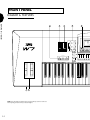
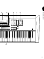

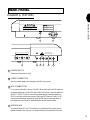


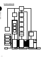
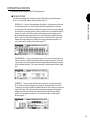

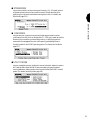
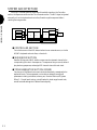


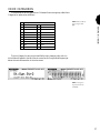

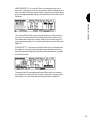
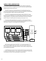
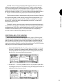
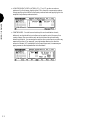
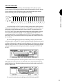

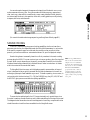
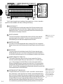

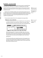
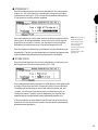
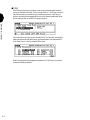

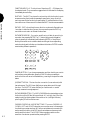
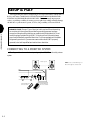
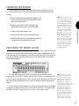

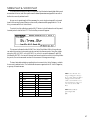
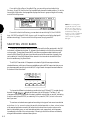


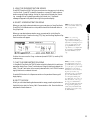
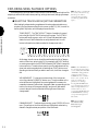
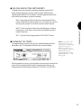


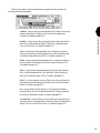


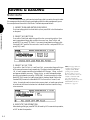
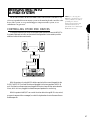
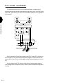
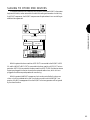


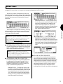

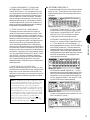
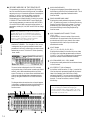
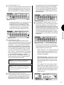
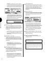

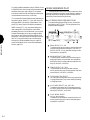


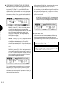
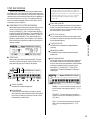
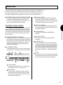

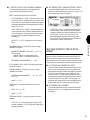


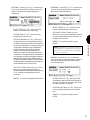
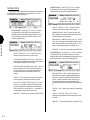

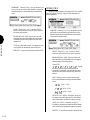

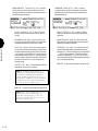
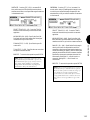
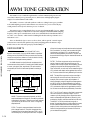
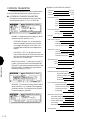

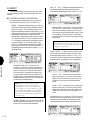
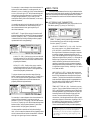

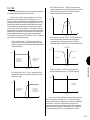

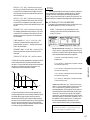
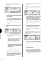

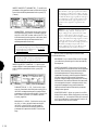
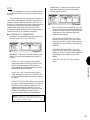
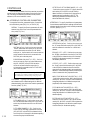
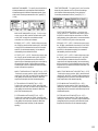
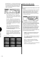
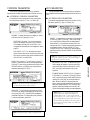

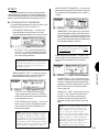

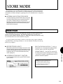


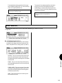
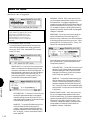


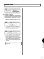
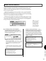

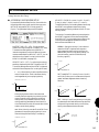


![hank yo_fo buyil_gaSamsung (}a_Te_a ]hs](http://vs1.manualzilla.com/store/data/005691502_1-2e8e29ffb67d0c8f7d0d701e3cb644b7-150x150.png)