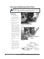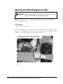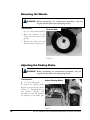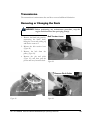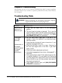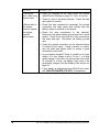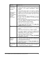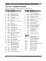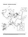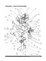
1
DR ALL-TERRAIN FIELD and BRUSH MOWER Safety & Operating Instructions Please read instructions before operating machine And congratulations on your purchase of a new DR ALL-TERRAIN FIELD and BRUSH MOWER! We have done our utmost to ensure that your DR ALL-TERRAIN FIELD and BRUSH MOWER will be one of the most trouble-free and satisfying pieces of equipment you have ever owned. Please let us know of any questions or problems you may have. We want to answer or correct them as quickly as possible. (When you do call, please have your serial number and/or order number handy—it will speed things up!) We also hope to hear from you on how much you like your new helper. And, please tell your friends about your new DR ALL-TERRAIN FIELD and BRUSH MOWER! Having DR Owners spread the word about our products and our way of doing business is the best advertising we can have, and the best way to help us provide even better service in the years to come. Thanks once again! for all of us at Country Home Products, Inc. COPYRIGHT 2005 Country Home Products, Inc. All rights reserved. DOCUMENTATION Written by: Ed Melen of EVM Technical Writing Country Home Products, Inc. Meigs Road P.O. Box 25 Vergennes, VT 05491 Toll-free phone: 1-800-DR-OWNER (376-9637) Fax: 1-802-877-1213 Web site: www.dr-owner.com ii DR ALL-TERRAIN FIELD and BRUSH MOWER Safety & Operating Instructions Table of Contents Chapter 1: Introducing the DR ALL-TERRAIN FIELD and BRUSH MOWER......1 About This Manual ......................................................................................................................... 1 Chapter 2: Safety Considerations..........................................................................3 Preparing to Use the DR ALL-TERRAIN FIELD and BRUSH MOWER ......................................... 3 Safety Information Labels............................................................................................................... 3 Protecting Yourself ......................................................................................................................... 5 Operating the Machine Safely ........................................................................................................ 5 Slope Operation ............................................................................................................................. 6 Safety for Children.......................................................................................................................... 7 Safety with Gasoline-Powered Machines ....................................................................................... 7 A Note to All Users ......................................................................................................................... 8 Additional Information and Potential Changes................................................................................ 8 Chapter 3: Setting Up Your DR ALL-TERRAIN FIELD and BRUSH MOWER......9 DR ALL-TERRAIN FIELD and BRUSH MOWER Controls and Features ......................................10 Unpacking the Mower....................................................................................................................11 To Install the Brush Deck ..............................................................................................................12 Connecting the Battery Wire (Electric-Starting Models Only) ........................................................13 Adding Oil and Gasoline................................................................................................................14 Check the Tire Pressure................................................................................................................14 Chapter 4: Operating Your DR ALL-TERRAIN FIELD and BRUSH MOWER ....15 The Pre-Start Safety Check...........................................................................................................15 Before Starting the Engine ............................................................................................................16 Electric-Starting .............................................................................................................................16 Manual-Starting .............................................................................................................................16 Engaging the Wheel Drive.............................................................................................................17 Engaging the Blade .......................................................................................................................17 Stopping the Blade ........................................................................................................................17 Stopping the Engine ......................................................................................................................18 Obstacle Tips ................................................................................................................................18 Slopes ...........................................................................................................................................19 If the machine gets hung up ..........................................................................................................19 Cutting Brush & Saplings...............................................................................................................20 Reverse .........................................................................................................................................20 Cutting in Wet & Heavy Growth.....................................................................................................20 Cold Weather Operation................................................................................................................20 Chapter 5: Maintaining the DR ALL-TERRAIN FIELD and BRUSH MOWER....21 Regular Maintenance Check List...................................................................................................21 Battery Care (For Electric-Starting Models Only) ..........................................................................22 Charging the Battery .....................................................................................................................22 Lubrication.....................................................................................................................................23 Grease Fittings ..............................................................................................................................24 Removing and Replacing the Belts ...............................................................................................25 Removing and Replacing the Blade ..............................................................................................28 Adjusting the Wheel Clutch ...........................................................................................................29 Removing and Replacing the Drive Chain.....................................................................................30 Adjusting the Blade Engagement Cable ........................................................................................31 Removing the Wheels ...................................................................................................................32 Adjusting the Parking Brake ..........................................................................................................32 Transmission .................................................................................................................................33 Removing or Changing the Deck...................................................................................................33 End of Season & Storage ..............................................................................................................34 DR ALL-TERRAIN FIELD and BRUSH MOWER Safety & Operating Instructions iii Chapter 6: Troubleshooting .................................................................................35 Troubleshooting Table...................................................................................................................35 Chapter 7: Parts Lists, Schematic Diagrams and Warranty ..............................40 Parts List — Handlebar Assembly.................................................................................................40 Schematic – Handlebar Assembly.................................................................................................41 Parts List — Power Unit Assembly................................................................................................42 Schematic – Power Unit Assembly................................................................................................43 Parts List — Brush Deck Assembly...............................................................................................44 Schematic – Brush Deck Assembly...............................................................................................45 Parts List — Differential/Axle Assembly ........................................................................................46 Schematic – Differential/Axle Assembly ........................................................................................47 Warranty........................................................................................................................................49 iv DR ALL-TERRAIN FIELD and BRUSH MOWER Safety & Operating Instructions Chapter 1: Introducing the DR ALL-TERRAIN FIELD and BRUSH MOWER This manual will help you set up and safely operate your new DR ALLTERRAIN FIELD and BRUSH MOWER. Careful adherence to the safety and operating instructions in this manual will ensure many years of productive use. Please let us know of any questions you may have. We want to answer them as quickly as possible. When you do call, please have your order number handy. For technical assistance, please call Toll-Free 1-800-DR-OWNER (376-9637) and one of our Technical Support Representatives will be happy to help you. About This Manual This manual is broken down into seven main chapters: Chapter 1: Introducing the DR ALL-TERRAIN FIELD and BRUSH MOWER ■ Explains the organization of this manual. ■ Provides contact information for Country Home Products, Inc. Chapter 2: Safety Considerations ■ Explains guidelines for safe operation of your machine. Chapter 3: Setting Up Your DR ALL-TERRAIN FIELD and BRUSH MOWER ■ Provides instructions for setting up and using your machine after shipment. Chapter 4: Operating Your DR ALL-TERRAIN FIELD and BRUSH MOWER ■ Provides instructions for starting and stopping the machine’s engine. ■ Provides tips for dealing with obstacles. Chapter 5: Maintaining the DR ALL-TERRAIN FIELD and BRUSH MOWER ■ Provides machine maintenance tips. Chapter 6: Troubleshooting ■ Lists common problems and their solutions. ■ Explains how to contact Country Home Products, Inc. should you need further assistance. Chapter 7: Parts Lists, Schematic Diagrams and Warranty Lists the parts of the mower with exploded views of the assemblies. Provides warranty information. In addition to these chapters, there is a section at the end of this manual for your notes as well as a checklist of daily maintenance procedures on the back cover, which will keep your mower performing well for years to come. DR ALL-TERRAIN FIELD and BRUSH MOWER Safety & Operating Instructions 1 Conventions used in this manual WARNING! The exclamation point within an equilateral triangle alerts you to essential operating, safety, and maintenance (servicing) instructions. Important! This information is important in the proper use of your machine. Failure to follow this instruction could result in injury to you or damage to your mower. Tip: This is a helpful hint to guide you in getting the most out of your mower. Tools Needed: This indicates you will need a special tool to perform a maintenance function on your machine. Note: This information may be helpful to you. If you are ever unsure about an action you are about to take, contact Country Home Product’s toll-free support at 1-800-DR-OWNER (376-9637). 2 DR ALL-TERRAIN FIELD and BRUSH MOWER Safety & Operating Instructions Chapter 2: Safety Considerations WARNING! This mowing machine is capable of amputating hands and feet and throwing objects. Failure to observe the following safety instructions could result in serious injury or death. Taking the time to read and observe all safety instructions will ensure many years of productive use from your DR ALL-TERRAIN FIELD and BRUSH MOWER and help you avoid injury. Please take a few moments to read the following guidelines for safely operating your new machine. Preparing to Use the DR ALL-TERRAIN FIELD and BRUSH MOWER ■ ■ Read these Safety & Operating Instructions and the engine owner’s manual before you use the DR ALL-TERRAIN FIELD and BRUSH MOWER. Become familiar with the controls, engine and service recommendations to ensure the best performance from your machine. Inspect the area in which you will be working. Look for rocks, logs, sticks, rope, wire, garden tools, etc., and remove these objects before mowing. Mowing over these objects could damage the machine and cause injury. Safety Information Labels Take some time to become familiar with the following standard safety cautions applicable to your mower. Replace damaged or missing safety labels immediately. (#148231) Read the Safety and Operating Instructions. Always wear safety glasses or goggles while operating the machine. Do not operate the machine near people or animals. Keep body parts away from the mower blade. Remove all objects that could be thrown by the mower blade. Use caution operating the machine on slopes. Make sure you add oil before starting the engine; the unit is shipped without oil. Fill the oil reservoir slowly to make sure you don’t overfill it. (#127811) Keep combustible substances away from the engine when it is hot. (#136841) DR ALL-TERRAIN FIELD and BRUSH MOWER Safety & Operating Instructions 3 To avoid injury, keep your hands and feet away from the spinning blade. (#136491) Move the throttle to the CHOKE position to start the engine (to the RUN or IDLE position if the engine is already warm). (#164541) This label shows the proper routing of the drive belt. (#164371) This label reminds you about the importance of reading and understanding the Safety & Operating Instructions manual and of paying attention to the safety warnings. (#164521) 4 DR ALL-TERRAIN FIELD and BRUSH MOWER Safety & Operating Instructions WARNING! The items listed in this section will help you keep your DR ALLTERRAIN FIELD and BRUSH MOWER running smoothly and, most importantly, prevent injury to yourself or others. Please review them carefully before starting your machine. Protecting Yourself ■ ■ ■ ■ ■ ■ Always wear the protective goggles or safety glasses with side shields while mowing to protect your eyes from possible thrown objects. Wear shoes with non-slip treads when using your DR ALL-TERRAIN FIELD and BRUSH MOWER. If you have safety shoes, we recommend wearing them. Do not use the machine while barefoot or wearing open sandals. Wear long pants while mowing. Avoid wearing loose clothing or jewelry, which might be caught on the mower’s moving parts. Use earmuffs or earplugs to protect your hearing. We recommend wearing gloves while mowing. Operating the Machine Safely ■ ■ ■ ■ ■ ■ ■ ■ ■ ■ ■ Keep bystanders at least 100 feet away from your work area at all times. Objects can be thrown far from the mower and at great speeds. To be safe, do not operate the machine near small children or pets, and never allow children to operate the mower. Disengage the blade and stop the engine when another person or pet approaches. Clear the area of objects such as rocks, toys, wire, bones, sticks etc., which could be picked up and thrown by the blade. Be sure all blade and wheel controls are DISENGAGED before attempting to start the engine. Engage and disengage the blade a few times to get used to it before mowing. Keep your hands and feet away from the blade, belts, chains, blade pulleys, and concealed areas while the engine is running. NEVER reach under the deck or grab hold of any part of the deck when the engine is running. ALWAYS shut off the engine whenever you leave the machine. Remove the spark plug wire(s) before adjusting the machine. If you have to stop to remove grass or debris from the underside of the deck, ALWAYS disconnect the spark plug wire(s) first. The exhaust area on the engine becomes very hot with use. Allow the engine to cool before doing maintenance or making adjustments. Keep combustible substances away from the engine when it is hot. When operating over uneven terrain and slopes, use EXTREME CAUTION to ensure solid and firm footing. Keep a firm hold on the handlebars and walk, never run. Stop the blade when crossing gravel drives, walks, or roads. Use the machine only in daylight or good artificial light. Use extra caution when mowing in wet or slippery conditions. DR ALL-TERRAIN FIELD and BRUSH MOWER Safety & Operating Instructions 5 ■ ■ ■ ■ ■ ■ ■ ■ ■ ALWAYS OPERATE THE MOWER FROM BEHIND. Never pass or stand on the discharge (right) side or in front of machine when the engine is running. Do not pull the mower backwards unless absolutely necessary. Look down and behind before and while moving backwards. Do not, under any conditions, remove, bend, cut, fit, weld, or otherwise alter standard parts on the DR ALL-TERRAIN FIELD and BRUSH MOWER. This includes all shields and guards. Modifications to your machine could cause personal injuries and property damage and will void your warranty. See manufacture’s instructions for proper operation and installation of accessories. Only use accessories approved by Country Home Products, Inc. If the machine starts to make an unusual noise or vibration, immediately shut off the engine, disconnect the spark plug wire(s), and allow all moving parts to come to a complete stop. Vibration is generally a warning of trouble. Inspect for clogging or damage. Clean and repair and/or replace damaged parts. While using the DR ALL-TERRAIN FIELD and BRUSH MOWER, don't hurry or take things for granted. When in doubt about the equipment or your surroundings, stop the machine and take the time to look things over. Make sure that you have 100% control of the mower at all times. Never allow people who are unfamiliar with these instructions to use the DR ALLTERRAIN FIELD and BRUSH MOWER. Do not operate the machine when under the influence of alcohol or medication. Watch for traffic when mowing near roadways. Slope Operation Slopes are a major factor related to slip and fall accidents, which can result in severe injury. All slopes require caution. If you feel uneasy on a slope, do not mow it. DO: Mow across the face of slopes; never up and down. Exercise extreme caution when changing direction on slopes. Remove objects such as rocks, tree limbs etc. Watch for holes, ruts, or bumps. Tall grass can hide obstacles. DO NOT: Do not mow near drop-offs, ditches, or embankments. You could lose your footing or balance. Do not mow on slopes greater than 20 degrees or any excessively steep slopes. Do not mow on wet slopes. Reduced traction could result in slipping. 6 DR ALL-TERRAIN FIELD and BRUSH MOWER Safety & Operating Instructions Safety for Children Tragic accidents can occur if the operator is not alert to the presence of children. Children are often attracted to the mower and the mowing activity. Never assume that children will remain where you last saw them. Keep children out of the mowing area and under the watchful care of a responsible adult. Be alert and turn the mower OFF if children enter the work area. Before and while moving backwards, look behind and down for small children. Never allow children to operate the mower. Use extra care when approaching blind corners, shrubs, trees, or other objects that may obscure your vision. Safety with Gasoline-Powered Machines WARNING! Use extra care in handling gasoline. Gasoline is flammable and the vapors are explosive. Do not run the engine in an enclosed area or without proper ventilation. ■ Store all fuel in containers specifically designed and approved for this purpose. ■ Fill the gasoline tank outdoors with the engine off and allow the engine to cool completely. Don't handle gasoline if you or anyone nearby is smoking, or if you're near anything that could cause it to ignite or explode. ■ If you spill gasoline, do not attempt to start the engine. Move the machine away from the area of the spill and avoid creating any source of ignition until the gas vapors have dissipated. Wipe up any spilled fuel to prevent a fire hazard and properly dispose of the waste. ■ Allow the engine to cool completely before storing in any enclosure. Never store the machine with gas in the tank or a fuel container, near an open flame or spark such as a water heater. ■ Never make adjustments or repairs with the engine running. Disconnect the spark plug wire(s) and keep the wire(s) away from the spark plug(s) to prevent accidental starting. ■ Do not change the engine governor settings or modify the engine speed. ■ Keep all nuts and bolts, especially the blade attachment bolts, tight and keep the equipment in good operating condition. ■ Never tamper with safety devices. Check their proper operation regularly. ■ Keep the mower free of grass, leaves or other debris build-up. ■ Stop and inspect the equipment if you strike an object. Repair, if necessary, before restarting. ■ The mower blade is sharp and can cut. Wrap the blade or wear gloves, and use extra caution when serving them. Note: If situations occur that are not covered by this manual, use care and good judgment. Call Toll-Free 1-800-DR-OWNER (376-9637) for assistance. ■ DR ALL-TERRAIN FIELD and BRUSH MOWER Safety & Operating Instructions 7 A Note to All Users Under California law, and the laws of some other states, you are not permitted to operate an internal combustion engine using hydrocarbon fuels without an engine spark arrester. This also applies to operation on US Forest Lands. All DR ALL-TERRAIN FIELD and BRUSH MOWERS shipped to California and Washington State are provided with spark arresters. Failure of the owner/operator to maintain this equipment in compliance with state regulations is a misdemeanor under California law and may be in violation of other state and/or federal regulations. Contact your local fire marshal or forest service for specific information in your area. Additional Information and Potential Changes Country Home Products, Inc. reserves the right to discontinue, change, and improve its products at any time without notice or obligation to the purchaser. The descriptions and specifications contained in this manual were in effect at printing. Equipment described within this manual may be optional. Some illustrations may not be applicable to your machine. 8 DR ALL-TERRAIN FIELD and BRUSH MOWER Safety & Operating Instructions Chapter 3: Setting Up Your DR ALL-TERRAIN FIELD and BRUSH MOWER This chapter outlines a few simple steps you will need to follow to set up your new machine before you use it. It may be helpful to familiarize yourself with the controls and features on your mower by reviewing the picture in the next section before beginning the steps outlined in this chapter. DR ALL-TERRAIN FIELD and BRUSH MOWER Safety & Operating Instructions 9 DR ALL-TERRAIN FIELD and BRUSH MOWER Controls and Features Note: The model shown in Figure 1 may look slightly different from your machine. Throttle Control Blade Control Shift Lever Operator Presence Control Key Switch Fuel Fill Parking Brake Oil Fill Brush Deflector Discharge Chute Figure 1 10 DR ALL-TERRAIN FIELD and BRUSH MOWER Safety & Operating Instructions Unpacking the Mower NOTE: Unpacking the DR ALL-TERRAIN FIELD and BRUSH MOWER is a twoperson job. We recommend you have an extra set of hands available before you begin. Tools & Supplies Needed: Screwdriver Hammer Knife Gloves WARNING! The banding may have a lot of tension on it and may snap, cutting you when cut. Always stand to one side when cutting the band. 1. Stand to one side and cut the banding. 2. Remove the top of the carton. Cut the cardboard top to bottom on one of the narrow sides of the box and peel it off the pallet. Be careful of the staples. 3. Pry off the fasteners and cut any ties holding the machine to the pallet. 4. Remove the brush deck by lifting it up and over the supporting lumber, and then remove the lumber. You may need to remove one of the cross slats. At this point the lawn deck (if ordered) is free standing and can be lifted off the pallet. Caution: Wear gloves and be very careful when handling the deck(s). The blades are very sharp, and may spin as you maneuver the deck(s). 5. Roll the power unit off the pallet. 6. Attach the deck to the power unit following the directions on the next page. The belt is stored below the black pulley cover. WARNING! Before attaching the deck, be sure the spark plug wire(s) is disconnected. 7. If assembling the Lawn Deck, mount the front caster wheels before attaching the deck to the power unit. Note: The Safety and Operating Instructions and the caster wheels for the Lawn Deck (if ordered) are tucked in one of the cardboard corner supports. DR ALL-TERRAIN FIELD and BRUSH MOWER Safety & Operating Instructions 11 To Install the Brush Deck WARNING! Before performing any maintenance procedure, stop the engine and disconnect the spark plug wire(s). 1. Remove the black belt guard by unscrewing the black knob, lifting the cover and pulling up and back to remove it. The belt is shipped wrapped around the pulley. 2. Slide the power unit shaft into the brush deck and install collar and pin (Figure 2). 3. Install the belt on the pulley and clutch (Figure 3) and route the belt per the label on the spindle housing (Figure 4). The tension lever may have to be released and secured into slot. (Figure 5). 4. Release the belt tensioner (Figure 5) onto the belt. 5. Replace the belt guard and secure in place with the black knob. Install Collar and Pin Install Belt Figure 2 Figure 3 Belt Tension Lever Figure 4 12 Figure 5 DR ALL-TERRAIN FIELD and BRUSH MOWER Safety & Operating Instructions Connecting the Battery Wire (Electric-Starting Models Only) We ship all electric-starting mowers with the negative terminal battery wire disconnected. This prevents the battery from discharging during shipment. Before using your mower, you must connect the battery wire. Tools Needed: (2) 5/16 wrenches or sockets 1. Connect the negative wire to the negative terminal on the battery (Figure 6). Connect Battery Wire Figure 6 DR ALL-TERRAIN FIELD and BRUSH MOWER Safety & Operating Instructions 13 Adding Oil and Gasoline WARNING! You must add oil before starting the engine. This machine is shipped without oil. Traces of oil may be in the reservoir from factory testing, but you must add oil before starting the engine. Fill the reservoir slowly checking the dipstick frequently to avoid overfilling. Important! To get an accurate reading when checking the oil level: ⇒ The machine should be on a level surface. ⇒ The dipstick should be screwed down on Briggs & Stratton engines. ⇒ The dipstick should NOT be screwed down on Kawasaki engines. Tip: To avoid confusion, we recommend leaving the caps on the fuel and oil fills until you are ready to pour either gasoline or oil into the correct fill. Use only SAE 30 high detergent oil. Other types of oil could cause problems operating your machine. Please refer to your engine manufacturer’s owner’s manual for detailed oil information. 1. Place the machine on a level surface and initially add ½ of the SAE 30 high detergent oil recommended by the engine manufacturer and wait one minute for the oil to settle (Figure 1). 2. Check the dipstick and continue adding a few ounces of oil at a time, rechecking the dipstick until the oil reaches the fill mark. Be careful not to overfill. Approximate Engine Oil Required w/ Oil Filter Briggs & Stratton – 11.5 HP 48 oz. (1.42 L) Briggs & Stratton – 13 HP 48 oz. (1.42 L) Kawasaki – 15 HP 57.6 oz. (1.7 L) Kawasaki – 17 HP 57.6 oz. (1.7 L) 3. Fill the gas tank to within ¼ inch of the top with fresh, unleaded gas. See your engine manufacturer’s owner’s manual for more information. 4. Open the fuel shut-off valve (on the bottom of the gas tank) if your model is equipped with one. Check the Tire Pressure There should be 14 psi in each tire. 14 DR ALL-TERRAIN FIELD and BRUSH MOWER Safety & Operating Instructions Chapter 4: Operating Your DR ALL-TERRAIN FIELD and BRUSH MOWER This chapter covers the procedures for starting and stopping your new DR ALLTERRAIN FIELD and BRUSH MOWER and discusses basic operation features. You may find it helpful to review the DR ALL-TERRAIN FIELD and BRUSH MOWER Controls and Features picture (Figure 1) on page 10 before reading this chapter. The Pre-Start Safety Check Your DR ALL-TERRAIN FIELD and BRUSH MOWER is fitted with an Operator Presence System to prevent it from functioning without an operator in the proper position at the controls. Also, normal wear and tear can bring about the need for adjustment to some running parts to insure that they function properly in terms of safe operation. For your protection, it is imperative that these simple test procedures be performed before each use of the machine to verify that the safety equipment is in good order and that no part adjustments are needed for safe operation. Test your Operator Presence Control System: 1. Stand in the operating position behind the handlebars, start your machine and engage the blade. 2. Remain behind the handlebars and release both hands from the controls. 3. THE ENGINE SHOULD SHUT OFF IMMEDIATELY. If your engine does not stop, your Operator Presence Control System may be damaged or disabled. WARNING! Turn off your machine by using the ignition key and stop using your machine immediately! Inspect the system for the following: Intentional disabling of the system through part modification or temporary measures used to override the system. Loose electrical connections. Broken parts. After inspection, repeat this test. If your system still does not operate properly, REMOVE THE KEY FROM THE IGNITION SWITCH TO PREVENT OTHERS FROM OPERATING THE EQUIPMENT. Call our Technical Support Representatives at 1(800) DR-OWNER (376-9637). DR ALL-TERRAIN FIELD and BRUSH MOWER Safety & Operating Instructions 15 Checking and adjusting clutch engagement: 1. Start your machine in the normal manner. 2. With the operator presence lever depressed, shift into low gear. 3. Increase the engine rpm but do not squeeze the clutch lever. The machine should not move when the clutch lever is not squeezed WARNING! If your machine “creeps” during this test, your clutch needs adjustment. Consult Chapter 5, page 29 of your Safety & Operating Instructions manual and make all necessary corrections before using. Before Starting the Engine 1. Check the oil level every time you use the machine. 2. Check the gas level. 3. Open the fuel shut-off valve (on the bottom of the gas tank), if your model is equipped with one. Electric-Starting 1. Move the Shift Lever to N (Neutral). See mower picture, Figure 1, on page 10. Note: Shift lever MUST be in neutral or the engine will not start. 2. Move the Throttle (Figure 1) to the CHOKE position (to the RUN position if the engine is already warm). 3. Turn the Key (Figure 1) to the START position until the engine starts, then release. The key will snap back to the RUN position and the engine will continue to run. 4. Move the Throttle to the RUN position. Manual-Starting 1. Move the Throttle (see mower picture, Figure 1, on page 10) to the CHOKE position (to the RUN position if the engine is already warm). 16 2. Turn the Key (Figure 1) to START. 3. Grasp the recoil starter handle and slowly pull until you feel resistance. Let the cord retract a little bit, then pull the cord rapidly to start the engine. One or two pulls usually starts the DR ALL-TERRAIN FIELD and BRUSH MOWER. 4. Move the Throttle to the RUN position. DR ALL-TERRAIN FIELD and BRUSH MOWER Safety & Operating Instructions Engaging the Wheel Drive The DR ALL-TERRAIN FIELD and BRUSH MOWER has a four-speed forward transmission and single-speed reverse. Forward speeds range from 1.1 mph in first gear to 4.5 mph in fourth gear. Use the lower gears for mowing in thick, woody vegetation and the higher gears for wide-open areas and lighter vegetation, or as "travel gears." Reverse is ideal for maneuvering in tight spots. Note: Always release the wheel clutch lever (see mower picture, Figure 1, on page 10) when shifting gears. 1. Move the Shift Lever to the desired gear. 2. Disengage the Parking Brake. 3. Gently squeeze the Wheel Clutch Lever to engage a gear. 4. Release the Wheel Clutch Lever if you need to slow down or stop. Engaging the Blade 1. Hold down the Operator Presence Lever (see mower picture, Figure 1, on page 10). 2. Engage the Blade Control Lever. Note: If you engage the Blade Control Lever before holding down the Operator Presence Lever the engine will shut off. WARNING! Always disengage the blade of the DR ALL-TERRAIN FIELD and BRUSH MOWER before shifting into reverse. Stopping the Blade Pull the Blade Control Lever (see mower picture, Figure 1, on page 10) back to the DISENGAGED position. Note: Releasing the operator presence lever while the blade is engaged will cause the engine to shut off. DR ALL-TERRAIN FIELD and BRUSH MOWER Safety & Operating Instructions 17 Stopping the Engine 1. Disengage the blade by pulling the Blade Control Lever (see Figure 1, on page 10) back to the DISENGAGED position. 2. Move the Shift Lever to the N (Neutral) position. 3. Move the Throttle Control to the IDLE position. 4. Turn the Key to the OFF position and remove it for safety. 5. Set the Parking Brake. Note: If your machine is equipped with a fuel shut-off valve, close it when transporting or storing the mower. Obstacle Tips Dealing with obstacles in the terrain is easy with your new DR ALL-TERRAIN FIELD and BRUSH MOWER. The following section explains how to approach most common obstacles. WARNING! The mower engine's power can easily throw stones, sticks and other debris at great velocity, which could cause personal injury or property damage. DO NOT run the machine over gravel driveways or over loose stones or mulch with the mower blade spinning. ■ ■ 18 Always check your work area before mowing and remove any debris that might tangle or damage the machine. If you do run into debris and the mower becomes tangled, turn off the engine and disconnect the spark plug wire(s) before attempting to untangle the machine. DR ALL-TERRAIN FIELD and BRUSH MOWER Safety & Operating Instructions Slopes WARNING! When operating the DR ALL-TERRAIN FIELD and BRUSH MOWER over uneven terrain or slopes, use EXTREME CAUTION not to tip the machine over. 1. Do not use the DR ALL-TERRAIN MOWER on slopes greater than 20 degrees. Doing so could result in serious injury or damage to your machine. 2. To avoid freewheeling, shift into a lower gear before going down a slope. Do not shift while on a slope. 3. Note that the mowing deck pivots from side to side (15 degrees in either direction), which helps avoid scalping, and keeps the weight balanced over the drive wheels when operating on uneven terrain (Figure 7). Figure 7 If the machine gets hung up 1. Disengage the blade. Do not try to free the machine from stumps or debris while the blade is engaged. 2. Try putting the machine in reverse and backing away from the obstacle. 3. Try pushing down on the handlebars to lift the mowing deck over the obstacle (Figure 8). Push Down on Handlebars to Clear Debris Figure 8 WARNING! If you need to leave the operating position to clear debris from the deck, first put the machine in "N" (Neutral), turn the engine off, set the brake and disconnect the spark plug wire(s). WARNING! DO NOT touch the exhaust areas when reaching for the spark plug(s)—they are very hot. DR ALL-TERRAIN FIELD and BRUSH MOWER Safety & Operating Instructions 19 Cutting Brush & Saplings 1. When cutting woody material, small saplings, etc., allow the machine to ride up and over material slowly. Adjust your forward speed to varying conditions (Figure 9). 2. After cutting brush, etc., you may want to mow over it again to remove any remaining branches. It works best to mow from the trunk end toward the top as brush lies on the ground. Reverse Figure 9 1. Be very careful of your footing when operating the machine in reverse. Know what's behind you and take your time. 2. Disengage the blade before shifting into reverse. Mow in the forward gears only, using reverse for maneuvering. 3. If you find it difficult to shift into reverse, lightly "feather" the Clutch Lever as you put the Shift Lever into reverse, then quickly release the Clutch Lever. Cutting in Wet & Heavy Growth 1. Be very careful of your footing when mowing in wet conditions. Avoid steep slopes and other slippery areas. 2. Use a lower, slower speed when mowing in wet conditions. Cold Weather Operation At temperatures below 30°F and a high dew point, your ATM engine may experience icing of the carburetor and/or the crankcase breather system. Country Home Products, Inc. offers an optional engine cover to prevent icing in these weather conditions. The cover can be purchased through Country Home Products, Inc. by calling 1(800) DROWNER (376-9637). Please have your ATM Model# and Serial# at hand when the call is placed. Tip: As a preventative measure to prevent control cable freeze up; prior to using your ATM in cold weather, inject “dry gas” into the Brake and Clutch cable-housing openings to absorb any moisture that may have collected. Tip the machine forward slightly so the “dry gas” will flow down the inside of the housings, and then lubricate as outlined on page 23. 20 DR ALL-TERRAIN FIELD and BRUSH MOWER Safety & Operating Instructions Chapter 5: Maintaining the DR ALL-TERRAIN FIELD and BRUSH MOWER This chapter covers regular maintenance procedures that will ensure the best performance and long life of your machine. For engine maintenance, please refer to the engine owner’s manual that came with your mower. Service intervals listed in the checklist below supercede those listed in the engine owner’s manual. WARNING! Some of the following procedures require access to the underside of the machine. If you need to tip the machine back or on its side (with the discharge chute facing up), you must first disconnect the spark plug wire(s), drain the oil and gas, and remove the air filters. Regular Maintenance Check List Note: Service intervals shown are considered maximum under normal operating conditions. Increase frequencies under extremely dirty or dusty conditions. Before Each Use Procedure Check Operator Presence Switch ▲ Check Engine Oil Level ▲ Check General Equipment Condition ▲ Check Blade for Sharpness ▲ Every 25 Hours Lubricate Grease Fittings ▲ Lubricate Clutch & Brake Cables ▲ Lubricate Chain ▲ Check Tire Pressure ▲ Clean Air Filter & Precleaner* ▲ Change Engine Oil & Filter* 1st time 5 hours Every 100 Hours ▲ Check Parking Brake Adjustment ▲ Clean Engine Exterior & Cooling Fins ▲ Check All Belt Tensions & Condition ▲ Check cable connections ▲ Replace Spark Plug(s) ▲ Replace Air Filter & Precleaner ▲ * The engine on your DR may not have a precleaner or oil filter. DR ALL-TERRAIN FIELD and BRUSH MOWER Safety & Operating Instructions 21 Battery Care (For Electric-Starting Models Only) Proper care can extend the life of a battery. Follow these recommendations to ensure your battery’s best performance and long life: ■ ■ ■ ■ Do not allow the battery charge to get too low. If the machine is not used, the battery should be charged every 4 – 6 weeks. Engine must be operated for at least 45 minutes to maintain proper battery charge. Store an unused battery in a dry area that does not freeze. Do not charge an already charged battery. In theory, our battery cannot be overcharged with a trickle charger; however, when a battery is fully charged and the charger is still on, it generates heat that could be harmful to the battery. A fully charged battery will read 12V-13.2V with a voltmeter. Do not continue to crank your engine when the battery charge is low. Symptoms of a battery needing a charge: The machine won’t start with the key, but will start with the recoil starter. ■ A whirring noise coming from the starter. ■ A grinding noise and a whirring noise coming from the starter. ■ No noise at all. ■ Charging the Battery The mower engine must be operated for at least 45 minutes to maintain proper battery charge. If the battery loses its charge, you'll need to use a trickle charger (like the DR Battery Charger) to recharge it. The charger should have an output of 12 volts at no more than 2 amps. ■ ■ At 1 amp the battery may need to be charged for as long as 48 hours. At 2 amps, the battery may need to be charged for as long as 24 hours. Note: Using the recoil starter and then running the engine will not recharge a dead or significantly discharged battery. To connect a battery charger to your DR ALL-TERRAIN FIELD and BRUSH MOWER, follow the steps listed below. 1. Detach the two battery wires going to the wiring harness on your DR ALL-TERRAIN FIELD and BRUSH MOWER. 2. Attach the black (-) battery charger wire to the black (-) wire, and attach the red (+) battery charger wire to the red (+) wire. 3. Plug the battery charger into an outlet. Important! When you are finished charging the battery, disconnect the battery charger wires from the battery first, then disconnect the charger from the outlet. If the battery charger wires are left connected to the battery, the battery will discharge itself back into the charger. 22 DR ALL-TERRAIN FIELD and BRUSH MOWER Safety & Operating Instructions Lubrication Your DR ALL-TERRAIN FIELD and BRUSH MOWER was greased at the Factory. The operator needs to lubricate the Wheel Clutch Cable, Brake Cable, Belt Idler Arm and the Drive Chain, periodically. Tools & Supplies Needed: ■ Flexible hose grease gun ■ Lithium grease ■ 1/2" wrench or socket (chain cover) ■ FLUID FILM® or comparable lubricant WARNING! Before performing any maintenance procedure, stop the engine and disconnect the spark plug wire(s). Lubricate the Parking Brake cable and Wheel Drive Clutch cable with FLUID FILM® or comparable lubricant. Spray the lubricant into the cable housing while working the cable back and forth and few times. This should be done at both ends of the cables (Figure 10). Perform this lubrication more often in dry and dusty environments. Brake Cable Clutch Cable Lubricate Lubricate Lubricate Figure 10 DR ALL-TERRAIN FIELD and BRUSH MOWER Safety & Operating Instructions 23 Grease Fittings 1. There is one grease fitting below the black belt guard that needs maintenance (Figure 11): ■ The belt idler arm should have 1-2 pumps of grease every 25 operating hours. Belt Idler Arm Grease Fitting Note: Over greasing will cause grease to leak out of the seals onto the mower drive belt. Unless instructed Figure 11 otherwise, pump only until you feel slight resistance (1-2 pumps). 2. The drive chain should be lubricated with FLUID ® FILM lubricant or SAE 30 oil every 25 operating hours— more often if the machine is operated in extremely dusty or wet conditions. Remove the chain cover, lubricate the chain and replace the cover Remove Chain Cover (Figures 12 and 13). Figure 12 Lubricate Chain Figure 13 24 DR ALL-TERRAIN FIELD and BRUSH MOWER Safety & Operating Instructions Removing and Replacing the Belts WARNING! Before performing any maintenance procedure, stop the engine and disconnect the spark plug wire(s). Important! Use only DR belts on your machine. They have been thoroughly tested and proven for many hours of use. To Replace the Blade Belt 1. Remove the black belt guard by unscrewing the black knob, lifting the cover, and pulling up and back to remove it. Belt Tension Lever 2. Release the belt tension lever (Figure 14). 3. Remove the belt from the pulley (Figure 15), and then drop it from the engine pulley below the machine. 4. To mount the belt, follow the above procedure in reverse. Figure 14 Belt Removed Figure 15 DR ALL-TERRAIN FIELD and BRUSH MOWER Safety & Operating Instructions 25 To Replace the Drive Belt WARNING! Before performing any maintenance procedure, stop the engine and disconnect the spark plug wire(s). Tools Needed: ■ 7/16" socket ■ 1/2" wrench ■ 9/16" wrench ■ Gloves 1. Drain the gas and oil. 2. Remove the blade belt following the instructions as outlined in the previous page. 3. Remove the pin and collar (Figure 16), and then pull the power unit away from the deck. 4. Tilt the power unit forward onto the attachment pin. Remove Pin & Collar Figure 16 26 DR ALL-TERRAIN FIELD and BRUSH MOWER Safety & Operating Instructions 5. Remove the nuts on the clutch bracket and the clutch drive spring (Figure 17). 6. Remove the spring (Figure 18). Remove Belt Guides Spring Clutch Bracket Spring Remove Nuts Figure 18 Figure 17 7. Lift and swing the clutch bracket out of the way (Figure 18). 8. Remove the three belt guides (Figure 18). 9. Loosen the belt retainer bolts on the outside of the frame (one on each side) and slide the retainer back (Figure 19). 10. Remove the belt. 11. To mount the new belt, reverse the above procedure. Loosen Bolt and Slide Back Figure 19 DR ALL-TERRAIN FIELD and BRUSH MOWER Safety & Operating Instructions 27 Removing and Replacing the Blade WARNING! Before performing any maintenance procedure, stop the engine and disconnect the spark plug wire(s). Tools Needed: ■ 15/16" wrench or socket ■ Air wrench if available ■ Wear gloves ■ 2 x 4 to brace the blade 1. Block the blade with a piece of wood between the blade and the skid on the chute side of the deck (Figure 20). 2. Remove the blade lock nut (righthand, regular thread) and washer. Figure 20 WARNING! Use caution when pushing or pulling the wrench next to the blade. Wear gloves, if the wrench slips off the nut, you may be seriously injured. 3. Remove the blade. 4. Mount the new blade, washer and lock nut. Note: Be sure the blade is seated completely over the small ridge in the spindle hub before tightening the lock nut. 28 DR ALL-TERRAIN FIELD and BRUSH MOWER Safety & Operating Instructions Adjusting the Wheel Clutch WARNING! Before performing any maintenance procedure, stop the engine and disconnect the spark plug wire(s). Note: When properly adjusted, tension on the wheel clutch lever should increase when the lever is about parallel to (almost touching) the handlebar grip. Tools Needed: ■ (2) 1/2" wrenches 1. Find the wheel clutch adjustment on the clutch bracket on the underside of the machine (Figure 21). 2. Loosen the nut on the front (threaded) side of the bracket by 1/8" to 1/4", and then tighten the nut on the back against the bracket. Check the tension on the clutch lever and repeat the adjustment as needed. WARNING! If clutch is over tightened, machine may lurch forward when shifting into gear. Use caution when shifting into gear. Wheel Clutch Adjustment Figure 21 DR ALL-TERRAIN FIELD and BRUSH MOWER Safety & Operating Instructions 29 Removing and Replacing the Drive Chain WARNING! Before performing any maintenance procedure, stop the engine and disconnect the spark plug wire(s). Tools Needed: ■ 1/2" wrench or socket (chain cover) ■ Flat-head screwdriver ■ Needle Nose Pliers 1. Remove the Chain Cover (Figure 22). 2. Remove the Tensioner Spring (Figure 23). 3. Remove the Master Chain Link (Figure 24). First remove the Lock Clip by spreading the clip with the screwdriver and at the same time, slide the Lock Clip back off the Master Link pins with the needle nose pliers. Next, remove the Side Plate, and then remove the Master Chain Link. Remove the Chain Cover Figure 22 Remove Tensioner Spring 4. Slowly feed the chain out. 5. Mount the new chain as shown in Figure 23. Figure 23 Master Link 6. Add the Master Chain Link (Figure 24) in the reverse order of step 3. 7. Replace the Chain Cover and tighten the lock nuts. Side Plate Lock Clip Figure 24 30 DR ALL-TERRAIN FIELD and BRUSH MOWER Safety & Operating Instructions Adjusting the Blade Engagement Cable WARNING! Before performing any maintenance procedure, stop the engine and disconnect the spark plug wire(s). Note: If the blade won't cut, or seems to slip in heavy material, check the blade engagement cable. Tool Needed: ■ 1/2" open-end wrench On the right handlebar there is a black bracket for adjusting the blade engagement cable (Figure 25). To tighten the cable, turn the center portion of the adjuster counter clockwise. To loosen the cable, turn the adjuster clockwise. Blade Engagement Cable Adjustment Figure 25 DR ALL-TERRAIN FIELD and BRUSH MOWER Safety & Operating Instructions 31 Removing the Wheels WARNING! Before performing any maintenance procedure, stop the engine and disconnect the spark plug wire(s). Tool Needed: Remove Nuts ■ 3/4" socket with extension 1. Block the machine so the wheel to be removed is off the ground. 2. Remove the three nuts and slide the wheel off (Figure 26). Figure 26 Adjusting the Parking Brake WARNING! Before performing any maintenance procedure, stop the engine and disconnect the spark plug wire(s). Tool Needed: ■ 1/2" open-end wrench Adjust Parking Brake To adjust the parking brake, tighten or loosen the nut shown in Figure 27. Tightening the nut will increase pressure and loosening the nut will decrease the pressure on the brake pad. Figure 27 32 DR ALL-TERRAIN FIELD and BRUSH MOWER Safety & Operating Instructions Transmission The transmission is maintenance-free and does not need additional lubrication. Removing or Changing the Deck WARNING! Before performing any maintenance procedure, stop the engine and disconnect the spark plug wire(s). 1. Remove the black belt guard by unscrewing the black knob, lifting the cover and pulling up and back to remove it. Belt Tension Lever 2. Release the belt tension lever (Figure 28). 3. Remove the belt from the pulley (Figure 29). 4. Remove the pin and collar (Figure 30), and then pull the power unit away from the deck. Figure 28 Remove Pin & Collar Belt Removed Figure 29 Figure 30 DR ALL-TERRAIN FIELD and BRUSH MOWER Safety & Operating Instructions 33 End of Season & Storage WARNING! Before performing any maintenance procedure, stop the engine and disconnect the spark plug wire(s). Note: Please refer to the engine owner's manual for engine-specific procedures. ■ ■ ■ ■ ■ ■ ■ ■ ■ Change the oil (and oil filter, if applicable). For winter use, use SAE 5 – 30 HD. Remove the spark plug(s) and pour about 1 ounce of motor oil into the cylinder hole. Replace the plug(s) and pull the recoil starter rope until you feel strong resistance. This will coat the piston and seat the valves to prevent moisture buildup. Clean/replace the air filters. Clean dirt and debris from the cylinder head cooling fins, blower housing, debris screen and muffler area of the engine. If your engine has a fuel filter, replace it. If your DR ALL-TERRAIN FIELD and BRUSH MOWER will be idle for more than 30 days, we recommend using a gas stabilizer. This will prevent sediment from gumming up the carburetor. If there is dirt or moisture in the gas or tank, remove it by draining the tank. Completely fill the tank with fresh, unleaded gas and add the appropriate amount of stabilizer or gasoline additive. Run the engine for a short time to allow the additive to circulate. Close the fuel shut-off valve, if your machine is equipped with one, to prevent carburetor overflow and leakage. Store the battery in a dry area that will not freeze. If the machine is not used over a long period, the battery should be charged every four to six weeks. See page 22. Remove any wrapped weeds from the blade bearing housing. Clean grass and debris from the top and underneath the mower deck with a stiff brush. Check the blade for nicks and wear. Remove the blade and sharpen, or have it professionally sharpened if needed. Note: For winter use, please refer to the attachment instructions. 34 DR ALL-TERRAIN FIELD and BRUSH MOWER Safety & Operating Instructions Chapter 6: Troubleshooting Most problems are easy to fix. Consult the troubleshooting table for common problems and their solutions. If you continue to experience problems call Country Home Products, Inc. for support. Troubleshooting Table WARNING! Before performing any maintenance procedure, stop the engine and disconnect the spark plug wire(s). SYMPTOM Recoil will not pull out or is difficult to pull. POSSIBLE CAUSE ⇒ Check that the blade lever is in the disengaged position. The engine won’t start manually. ⇒ Are you using fresh, clean gas? If the gas is old, change it. Use a fuel stabilizer if you keep gas longer than two months. ⇒ Check that the fuel shut-off valve is turned on, if your machine is equipped with one. ⇒ Check the fuel filter to see if it is clear. Remove the line from the engine side of the filter. If gas flows freely, it’s OK. ⇒ Check the throttle adjustment and travel. ⇒ Is the blade engagement lever down (disengaged)? It should be. ⇒ Is the spark plug(s) clean? If the spark plug(s) is dirty or cracked, change it. If it’s oily, leave it out, hold a rag over the plug(s) hole and pull the recoil cord several times to blow out any oil in the cylinder, then wipe off the plug(s) and reinsert it. (Please refer to the engine owner’s manual for enginespecific procedures.) ⇒ The recoil may be broken or jammed. Try to turn the engine pulley by hand, with the spark plug wire(s) off. If it turns, the recoil is broken or jammed. Call 1(800) DR-OWNER (376-9637) for assistance. ⇒ If your engine still won’t start, call 1(800) DR-OWNER (376-9637) for assistance. DR ALL-TERRAIN FIELD and BRUSH MOWER Safety & Operating Instructions 35 SYMPTOM The engine won’t start using electric-start. POSSIBLE CAUSE ⇒ Have you checked all the items under the section called Electric Starting on page 16? If not, do so now. (Please refer to the engine owner’s manual for enginespecific procedures.) ⇒ Check the wire connections—especially the ground connection, the large green wire coming from the battery, where it connects to the engine. ⇒ There is a fuse in the wiring harness. Check the fuse and replace if needed. ⇒ Check the wire connections to the solenoid. Disconnect the green battery ground wire first to avoid sparks. Check to be sure that all of the connections are clean and tight. Reconnect the battery ground wire. ⇒ Check the ground connection on the solenoid where it’s bolted to the frame. Using a wrench or socket, spin the bolts and tighten them to ensure a good connection to the frame. ⇒ Is your battery charged? Check it yourself or at a gas station. If it’s low, charge it with a 12-volt, 1 to 2 amp trickle charger. If you don’t use your mower for at least 45 minutes at a time, the battery may need to be periodically charged. See the Battery Care section on page 22. ⇒ If your battery is charged and your DR still won’t start, call 1(800) DR-OWNER (376-9637) for assistance. 36 DR ALL-TERRAIN FIELD and BRUSH MOWER Safety & Operating Instructions SYMPTOM The engine lacks power or is not running smoothly. (Please refer to the engine owner’s manual for enginespecific procedures.) Engine smokes. Machine is hard to get into reverse. The belt frays or rolls over the pulley. POSSIBLE CAUSE ⇒ Check the throttle travel and adjustment. ⇒ Is the air filter clean? If it’s dirty, change it following the procedure in the engine manufacturer’s owner’s manual. ⇒ Is the spark plug(s) clean? If it’s fouled or cracked, change it. If it’s oily, leave it out, hold a rag over the plug(s) hole and pull your recoil cord several times to blow out any oil in the cylinder, then wipe off the plug(s) and reinsert it. ⇒ Are you using fresh, clean unleaded gas? If it’s old, change it. Use a fuel stabilizer if you keep gas longer than two weeks or so. ⇒ Does your engine have the right amount of clean oil? If it’s dirty, change it following the procedure in the engine manufacturer’s owner’s manual. ⇒ Check the oil level and adjust as needed. ⇒ If your engine still lacks power, call 1(800) DROWNER (376-9637) for assistance. ⇒ Check the oil level and adjust as needed. ⇒ You may be operating the machine on too great an incline. ⇒ Check the air filter and clean or replace if needed. ⇒ You may be using the wrong oil—too light for the temperature. Refer to your Engine Manufacturer's Owner’s Manual for detailed information. ⇒ Clean the cooling fins if they’re dirty. ⇒ If the engine still smokes, call 1(800) DR-OWNER (376-9637) for assistance. ⇒ If you find it difficult to shift into reverse, lightly pull the clutch lever as you pull the shift lever into reverse then quickly release the clutch lever. ⇒ If the difficulty persists, call 1(800) DR-OWNER (3769637) for assistance. ⇒ A pulley groove may be nicked. Check the belt for wear and hard spots. File off any nicks on the pulley. ⇒ The belt may be stretched. Replace it. DR ALL-TERRAIN FIELD and BRUSH MOWER Safety & Operating Instructions 37 38 SYMPTOM The cut material is not being properly discharged out of the right side of the machine. POSSIBLE CAUSE ⇒ The discharge may be blocked. Disengage the blade, turn off the engine, set the brake and disconnect the spark plug wire(s), then check for debris. Heavier growth gets hung up under the machine and does not discharge. ⇒ Try removing the baffle under the front of the mowing deck. Blade vibrates when engaged. The blade is not cutting or is loose. ⇒ The blade may not be seated properly on the hub. Loosen the blade nut, reset the blade and tighten the nut. ⇒ The spindle bearings may be bad. ⇒ Call 1(800) DR-OWNER (376-9637) for assistance. ⇒ The blade may not be seated properly on the hub. Loosen the blade nut, reset the blade and tighten the nut. Wheels pulling left or right. ⇒ Check the tire pressure. There should be 14 psi in each tire. The Wheel Drive Clutch and/or Brake lever will freeze up during cold weather operation. ⇒ Moisture is getting into the cable housing(s) and freezing. Using a syringe, inject “dry gas” into the cable-housing opening to absorb the moisture. Tip the machine forward slightly so the “dry gas” will flow down the inside of the housing. After the ice blockage has thawed, lubricate the cable(s) with FLUID FILM® or comparable lubricant. See page 23. DR ALL-TERRAIN FIELD and BRUSH MOWER Safety & Operating Instructions DR ALL-TERRAIN FIELD and BRUSH MOWER Safety & Operating Instructions 39 Chapter 7: Parts Lists, Schematic Diagrams and Warranty Parts List — Handlebar Assembly Note: Part numbers listed are available through Country Home Products, Inc. Ref# Part# Description Ref# Part# Description 01 150041 Battery Shelf 28 111731 Screw, 5/16" – 18 x 1/2" 02 110761 Nut, Nylon Lock, 5/16" – 18 29 112111 Cable Throttle (B&S) 03 150311 Handlebar, Left Hand 139051 Cable, Throttle (Kawasaki) 04 150301 Handlebar, Right Hand 30 151401 Screw, 1/4" – 20 x 3/4", Tri-Lobe 05 134431 Bolt, HCS, 5/16" – 18 x 1.5" 31 112391 Washer, Flat, 3/8" USS 06 150221 Control Panel 32 110751 Nut, Nylon Lock, 3/8" – 16 07 110761 Nut, Nylon Lock, 5/16" – 18 33 120301 Screw, 3/8" - 16 x 1-1/2", Tri-Lobe 08 150391 Shift Lever 34 110961 Pin, Roll, 3/16" x 1" 09 112441 Washer, 1/2" ID x 3/4" OD x 1/8", 35 181131 Cable, Transmission Brake Nylon 36 151431 Pin, Clevis, 3/16" x 3/4" 10 101341 Battery Pad 37 165251 Cable, Traction Drive 11 104831 Battery, 17AH, 12V 38 165271 Wire Harness, Kawasaki, E/S 12 124511 Clamp, Battery 7-1/8" x 5-1/2" 165291 Wire Harness, B&S, M/S 13a 165171 Wheel Clutch Lever 165281 Wire Harness, B&S, E/S 13b 165181 Brake Lever with Lock 39 110761 Nut, Nylon Lock, 5/16" – 18 14 180591 Operator Presence Lever w/wire (not illustrated) 15 179231 Screw, 25mm 40 100241 Shift Arm with Hub 17 150861 Nut, 3/16", Push, Washer Cap 41 110971 Pin, Roll, 3/16" x 1-3/4" 18 164971 Guard, Switch, Operator 42 150141 Ground Wire (not shown) Presence Safety Labels 19 151311 Plug, Hour Meter Hole 136841 Caution Hot Surface Label 20 114561 Bolt, HCS, 1/4" – 20 x 1-3/4" Right Arrow, Briggs 22 110221 Grip, Shift Handle 136831 Caution Hot Surface Label 23 151181 Brake Cable Bracket Left Arrow, Kawasaki/Tec. 24a 164951 Ergonomic Grip, 1" OD, 4.5" L 124371 American Flag Label 24b 164961 Plain Grip, 1" OD, 4.5" L 127811 Warning: Add Oil Label 25 165191 Switch, w/Key, Snap-in, 153321 DR All Terrain Mower Name Label 4 Positions (Electric Start) 179401 Pulley Cover Label 165201 Switch, w/Key, Snap-in, 161541 Throttle Control Label 2 Positions (Manual Start) 161521 Control Panel Label 25A 157201 Key, AT2 Ignition Switch 136491 Danger, Deck Label 26 150151 Cable, PTO Clutch 164371 Blade Belt Routing 26A 152001 Lever, PTO Cable 27 40 150361 Knob, Blade Engage Cable DR ALL-TERRAIN FIELD and BRUSH MOWER Safety & Operating Instructions Schematic – Handlebar Assembly DR ALL-TERRAIN FIELD and BRUSH MOWER Safety & Operating Instructions 41 Parts List — Power Unit Assembly Note: Part numbers listed are available through Country Home Products, Inc. Ref# Part# 01 150261 02 160171 160181 160191 160881 03 150411 04 150291 05 150011 06 150531 07 150591 08 111141 09 151001 10 160331 11 150171 12a 164771 12b 164781 13 150101 14 150481 15 16 17 18 19 20 21 22 23 24 25 150181 150211 111871 150241 112391 150201 150611 151111 108501 150021 150501 26 27 28 150061 150461 112481 42 Description Frame, Main Engine, 11.5HP, B&S e/s Engine, 13HP, B&S, e/s Engine, 15HP, KAW, e/s Engine, 17HP, KAW, e/s Mount, Fuel Tank Fuel Tank Assembly Fuel Cap With Gauge Strap, 2.5 Gal Fuel Tank Transmission Pulley, V, 7" OD, 4L or A Belt Transmission Shift Arm Tie Rod, 7.47" L Chain Idler Support Plate Chain Idler Adjuster Arm (Outer) Chain Idler Adjuster Arm (Inner) Bushing, .328" ID, .500" OD, 2.32" L Pulley, Flat Idler, 1.875" OD, .375" Bore Guard, Chain Clutch, PTO Spacer, 1/4" ID, .375" OD, 1.0" L Debris Guard, 11.5" x 5.12" Washer, Flat, 3/8” (USS) Belt Guide, Engine Idler Arm, Traction Drive Bushing, Idler Traction Drive Pulley, Flat, Idler, 3.0" OD Anti-Rotation Strap Spring, E, 438" OD x .045" Wire x 2.5 L Belt, A31, 1/2" x 33" Pin, Detent, 1/4" x 2" Washer, Lock, 1/4" External Tooth Ref# 29 30 31 32 33 34 35 36 37 38 39 40 41 42 43 44 45 Part# 134431 112431 123211 110761 110751 119831 112391 151321 150071 112381 150451 150771 126861 167221 112411 123361 164801 Description Bolt, HCS, 5/16" – 18 x 1-1/2" Washer, Lock, 5/16" Split Bolt, HCS, 5/16" – 18 x 3/4" Nut, Nylon Lock, 5/16" – 18 Nut, Nylon Lock, 3/8" – 16 Bolt, HCS, 1/4" – 20 x 3/4" Washer, Flat, 3/8" USS Washer, Lock, 7/16" Split Bolt, HCS, 7/16" – 20 x 3-1/4" Washer, Flat, 1/4" USS Bolt, HCS, 5/16" – 18 x 1-3/4" Nut, Nylon Lock, 3/8" – 24 Bolt, HCS, 3/8" – 16 x 2" Neutral Switch Washer, Flat, 5/16" USS Bolt, HCS, 5/16" – 18 x 1-1/4" Chain Adjuster Spring, .750 OD x .085 x 2.5L Set Screw, 5/16" – 18 x 1/4" Washer, Lock, 1/4" Split Bolt, 1/4" – 20 x 1-1/2" 46 47 48 111691 101811 101451 49 50 51 52 111241 112391 126861 151381 53 54 55 56 151151 100941 138741 110731 111731 Ring, Retaining, 5/8" Washer, Flat, 3/8" USS Bolt, HCS, 3/8" – 16 x 2" Washer, 1.375" ID, 2.0" OD x .25" Thick Washer, 1.38" ID, 2.0" OD, .5" L Fuel Filter (B&S) (not illustrated) Fuel Filter (Kawasaki) (not illustrated) Nut, Nylon Lock, 1/4" – 20 Bolt, 5/16" – 18 x 1/2" 57 187551 Nut, Nylon, Low Profile DR ALL-TERRAIN FIELD and BRUSH MOWER Safety & Operating Instructions Schematic – Power Unit Assembly DR ALL-TERRAIN FIELD and BRUSH MOWER Safety & Operating Instructions 43 Parts List — Brush Deck Assembly Note: Part numbers listed are available through Country Home Products, Inc. Ref# Part# 01 164561 160621 02 157261 03 160091 04 150891 05 151331 06 07 08 09 10 11 12 13 14 15 44 164371 164451 164401 150831 150711 150641 151141 160511 160611 100481 160891 101771 Description Brush Deck, 26 inch Brush Deck, 30 Inch Spindle Support Assembly Shaft, Spindle Bearing, Ball, .787" Bore Key, Parallel, Round Ends, 1/4" x 3/16" x 7/8" Label, Belt Routing Pulley, V, 8.5" OD, 5L or B Belt Belt Tension Release Lever Idler Arm Bushing, Idler Anti-Wrap Guard Spindle Hub Baffle, 26 inch Baffle, 30 inch Blade, 26" Air Tip Blade, 30” Air Tip Blade Washer Ref# Part# 16 151271 17 150941 18 19 20 21 22 23 24 25 26 27 28 29 30 31 32 33 150721 160071 150691 110751 112391 123211 111521 150701 110761 145291 112411 150681 157271 143661 165231 187351 Description Pulley, Flat Idler, 4" x 3/8" Bore Spring, Extension, .112" Wire x .750" OD x 5" L Attachment Swivel Bushing Nut, Nylon Lock, 5/8" – 18 Bolt, HCS, 3/8" – 16 x 2-1/2" Nut, Nylon Lock, 3/8" – 16 Washer, Flat, 3/8" USS Bolt, HCS, 5/16" – 18 x 3/4" Bolt, HCS, 3/8" – 16 x 1" Bolt, HCS, 3/8" – 16 x 4" Nut, Nylon Lock, 5/16" – 18 Bolt, 5/16" – 18 x 3/4" Carriage Washer, Flat, 5/16" USS Belt, B63K, 5/8" x 66" Belt Cover Assembly Knob, 5/16" Bracket, Belt Tension Lever Bearing, Ball 2 Seal DR ALL-TERRAIN FIELD and BRUSH MOWER Safety & Operating Instructions Schematic – Brush Deck Assembly DR ALL-TERRAIN FIELD and BRUSH MOWER Safety & Operating Instructions 45 Parts List — Differential/Axle Assembly Note: Part numbers listed are available through Country Home Products, Inc. Ref# 01 02 03 04 05 06 07 08 09 10 46 Part# 150251 150621 151721 150191 165221 110761 123211 168241 168261 151971 Description Differential, Limited Slip Wheel & Tire, 18" x 6.50" – 8", Terrain, 5 Lug Wheel & Tire, 18" x 6.50" – 8", Turf, 5 Lug Chain, #40, 88 Pitches with Master Link Nut, Lug, 1/2" – 20 Nut, Nylon Lock, 5/16" – 18 Bolt, HCS, 5/16" – 18 x 3/4" Retaining Spring Ring Dust Cap Split Collar, 1.00 ID x 1.75 OD, Clamp-On w/Set Screws DR ALL-TERRAIN FIELD and BRUSH MOWER Safety & Operating Instructions Schematic – Differential/Axle Assembly DR ALL-TERRAIN FIELD and BRUSH MOWER Safety & Operating Instructions 47 Notes 48 DR ALL-TERRAIN FIELD and BRUSH MOWER Safety & Operating Instructions DR® POWER EQUIPMENT DR ALL-TERRIAN FIELD and BRUSH MOWER 1-Year Limited Warranty Terms and Conditions The DR ALL-TERRAIN FIELD and BRUSH MOWER is warranted for one (1) year against defects in materials or workmanship when put to ordinary and normal consumer use; ninety (90) days for any other use. The engine manufacturer warrants the engine separately. For the purposes of all the above warranties, “ordinary and normal consumer use” refers to non-commercial residential use and does not include misuse, accidents or damage due to inadequate maintenance. Country Home Products, Inc. certifies that the DR ALL-TERRAIN FIELD and BRUSH MOWER is fit for ordinary purposes for which a product of this type is used. Country Home Products, Inc. however, limits the implied warranties of merchantability and fitness in duration to a period of one (1) year in consumer use, ninety (90) days for any other use. The 1-Year Limited Warranty on the DR ALL-TERRAIN FIELD and BRUSH MOWER starts on the date the machine ships from our factory. The 1-Year Limited Warranty is applicable only to the original owner. The warranty holder is responsible for the performance of the required maintenance as defined by the manufacturer's owner's manuals. The warranty holder is responsible for replacement of normally wearing parts such as the drive belts, bearings, debris shield, battery, and spark plug(s). Attachments and accessories to the machine are not covered by this warranty. During the warranty period, the warranty holder is responsible for the machine transportation charges, if required. During the warranty period, warranty parts will be shipped by standard method at no charge to the warranty holder. Expedited shipping of warranty parts is the responsibility of the warranty holder. SOME STATES DO NOT ALLOW LIMITATIONS ON THE LENGTH OF IMPLIED WARRANTIES, SO THE ABOVE LIMITATIONS MAY NOT APPLY TO YOU. Country Home Products, Inc. shall not be liable under any circumstances for any incidental or consequential damages or expenses of any kind, including, but not limited to, cost of equipment rentals, loss of profit, or cost of hiring services to perform tasks normally performed by the DR ALL-TERRAIN FIELD and BRUSH MOWER. SOME STATES DO NOT ALLOW THE EXCLUSION OR LIMITATION OF INCIDENTAL OR CONSEQUENTIAL DAMAGES, SO THE ABOVE LIMITATIONS MAY NOT APPLY TO YOU. Customer Service Hotline Country Home Products, Inc.’s objective is to have 100% satisfied customers. For that reason, we operate a 6-day-a-week Technical Service Department for our Owners. You can access a Representative by dialing our TOLL-FREE Hotline at 1-800DR-OWNER (376-9637). The sole job of our well-trained and friendly folks is to ensure that you get any help you need in a timely fashion. They are there to answer all your questions including: (1) inquiries on any of the above warranties, (2) inquiries about replacement parts, or (3) your questions regarding service, maintenance and operation. Our Customer Service Representatives will also be happy to answer any of your questions regarding the separate warranties on all engines. However, to obtain service, repair or replacement of any engine within the time period covered by the manufacturer’s limited warranty, follow the instructions and warranty information specifically pertaining to those items provided by their separate manufacturers. Warranty THIS WARRANTY GIVES YOU SPECIFIC LEGAL RIGHTS, AND YOU ALSO HAVE OTHER RIGHTS, WHICH VARY COUNTRY HOME PRODUCTS, Inc. FROM STATE TO STATE. MEIGS ROAD, P.O. BOX 25, VERGENNES, VERMONT 05491 1-800-DR-OWNER (376-9637) • www.dr-owner.com ©2002 CHP, Inc. 151751 Daily Checklist for the DR FIELD and BRUSH MOWER To help maintain your DR ALL-TERRIAN FIELD and BRUSH MOWER for optimum performance, we recommend you follow this checklist each time you use your machine. [ ] OIL: With the machine on a level surface, check the engine oil level with the dipstick and add more if necessary (only add oil to the level indicated on the dipstick - DO NOT OVERFILL). Use SAE 30 high detergent motor oil. [ ] GAS: Fill the gas tank with clean, fresh, unleaded gasoline. Make sure the gas valve on the bottom of the tank is open, if your model is equipped with one. Always close the gas valve when storing your machine. [ ] ENGINE AIR COOLING SYSTEM: It is very important to keep the engine clean of debris. Remove grass and other built-up materials from the air intake screen before, during and after you mow. Regularly remove debris from the blower housing and cooling fins. A dirty engine retains heat and can cause damage to the internal engine parts. [ ] BELTS: Check the belts for wear, proper alignment and tension. [ ] BLADE: Check the blade for tightness, nicks and wear. Remove any wrapped weeds and grass from the blade bearing housing to prevent buildup. [ ] GENERAL CONDITION: Check the general condition of the machine, e.g.; nuts, bolts, welds etc. COUNTRY HOME PRODUCTS, Inc. MEIGS ROAD, P.O. BOX 25, VERGENNES, VERMONT 05491 1-800-DR-OWNER (376-9637) • www.dr-owner.com ©2005 CHP, Inc. 191001